Letter

Suppressing False Alarm in VideoSAR viaGradient-Weighted Edge Information

College of Electronic Science and Technology, National University of Defense Technology, No. 109 De Ya Road, Changsha 410073, China
*
Author to whom correspondence should be addressed.
Remote Sens. 2019, 11(22), 2677; https://doi.org/10.3390/rs11222677
Submission received: 2 October 2019 / Revised: 3 November 2019 / Accepted: 7 November 2019 / Published: 15 November 2019
(This article belongs to the Special Issue Airborne SAR: Data Processing, Calibration and Applications)

Abstract

:
VideoSAR (Video Synthetic Aperture Radar) technology provides an important mean for real-time and continuous earth observation, whereas the ever-changing scattering characteristics may destroy the accuracy of target motion perception and bring in massive false alarms subsequently. False alarms emerge easily in the edge region for its sharper variations of the scattering characteristics. Utilizing the gradient difference between the target shadow edge and other edge regions in the image, this letter proposes a VideoSAR false alarm reduction method based on gradient-weighted edge information. By considering the reasonable gradient and area of the overlapping edge region between changing region and background, this method could reduce the amount of false alarms ( P f a = 18.4 % ) and retain the correct shadow of moving target ( P d = 74.8 % ). Experiments on a real footage verify the excellent effect of the proposed method.

1. Introduction

Video Synthetic Aperture Radar (VideoSAR) is a novel microwave detection technology proposed by researchers from Sandia National Laboratories, which combines SAR imaging and video techniques together. This novel technique enables continuous surveillance over a specific area, thus is regarded as an important mean of real-time battlefield reconnaissance and continuous earth observation [1,2,3]. By performing high-framerate and high-resolution imaging of the ground area, one could obtain valuable information, especially the motion status of moving targets [4].
Shadow-based VideoSAR moving target detection holds the advantages of high positioning accuracy, high detection probability and low minimum detectable speed [5,6]. However, shadow also shows an unstable characteristics and varies with many factors, such as scattering characteristics, viewing angle, target speed and so forth. Figure 1 lists out the main causes of false alarms in VideoSAR. Among them, the variation of ground scattering characteristics, the changing of viewing angle and the impact of target direct energy return may cause some local gray-scale differences, which show up as edge regions in the image. Such phenomena could bring in massive false alarms and contaminate the pre-detection performance.
Various kinds of methods have been proposed to improve the effect of detection and false alarm reduction. References [7,8] averages the adjacent images to suppress the speckle noise and reduce the amount of false alarm. But little thought is given to the spatial distribution of false alarm in VideoSAR images. Reference [9] operates median filter to tackle with the small-size false alarms but such operation will inevitably smear the target shadow and impact the detection performance as well. In References [10,11], a knowledge-aided adaptive threshold GMTI - SAR moving target detection algorithm is proposed, which comprehensively utilizes shadow shape, position and intensity information to eliminate false alarms. However, a clear and stable shadow is required to carry out such algorithm, which can hardly be realized on most VideoSAR systems. In summary, conventional methods are realized primarily based on the entire image. They take little consideration on the spatial distribution regularities of false alarms and real targets, especially the edge information hidden in VideoSAR image sequence.
To solve the above-mentioned insufficiencies, we firstly give a fully discussion on the edge region formed by stationary or moving targets. Then their areas, gradients and values are deduced and compared. Finally, based on the derived distinctions, the false alarms in VideoSAR image sequence are suppressed via gradient-weighted edge information. All predetermined thresholds/values are related to the radar system parameters and their mathematical relations are deduced in detail.
In this letter, the edge regions of VideoSAR image sequence are weighted by their gradient and utilized to improve the accuracy of false alarm reduction. This letter is organized as follows. Section 2 discusses the concept of difference-based shadow detection algorithm. Then Section 3 explains the gradient distinction between background edge and moving target edge, then analyzes the category of false alarm in edge region. In Section 4, a VideoSAR false alarm reduction method based on gradient-weighted edge information is proposed and discussed in detail. Experiments on a real VideoSAR footage are presented in Section 5 to verify the effectiveness of the proposed method. Section 6 concludes the whole work.

2. Difference-Based Shadow Detection Algorithm

Moving target can be detected via shadow in VideoSAR and moving shadow can be detected via difference process. Difference-based algorithms are widely used in moving target detection in VideoSAR [6], which includes background difference, inter-frame difference and so forth. This section will give a brief introduction of difference-based shadow detection algorithm and indicate their deficiencies on false alarm reduction.
  • Background Difference: Difference-based algorithm which extracts motion regions by thresholding the difference between the current frame and the background template. It should be noted that background template can be modeled via many methods like median average, mean average and Mixture Gauss [12]. Normally background difference algorithm could obtain decent effect when image sequence owns a stationary, smooth background and clear, large-size targets.
  • Inter-Frame Difference: Difference-based algorithm which operates difference between adjacent frame and the current one. This algorithm holds the consensus that variation between adjacent frames is quite minor except for moving objects. In case of slow-moving objects, inter-frame difference can also be done between 2 longer-interval frames or among several frames (more than 2).
In this work, we combine the above 2 algorithms to form an effective difference-based shadow detection algorithm. This algorithm mainly includes background difference, symmetrical difference (2 inter-frame difference among 3 adjacent frames) and morphological filtering. This algorithm is regarded as a pre-detection module, which can be referred in Reference [9] for detailed information.

3. Analysis of Gradient Difference between False Alarm and Real Target in Edge Region

3.1. Shadow Region Analysis

In order to achieve both high framerate and azimuth resolution, VideoSAR system divides echo data into some continuous and overlapped segments and processes them to obtain an image sequence. The detailed imaging process can be referred to [13,14]. The shadow of moving target can be divided into two parts: non-cast shadow caused by the Doppler displacement of target energy and the cast shadow caused by the squint imaging of SAR sensor. References [8,10] fully derives the geometric characteristics of shadow and figures out its relationships to the target size, radar incident angle and target velocity. Here, a brief derivation is given to exploit the difference between the edge of moving target shadow and other edge in the image (denoted as background edge).
Figure 2 illustrates the formation of shadow in one image. Left-hand target is a stationary target (green filled box) and right-hand is a moving one (green dotted boxes). The shadow areas are illustrated by red border gray polygons. Right-hand target moves at a speed of v t and the angle with the azimuth is θ . Both targets are assumed with size L t × W t × H t , α is the look-down angle of the radar, the synthetic aperture time is T, which can be written as follows [15]
T = r λ c 2 ρ a V r
where r is the nearest range between radar platform and target, λ c is the carrier wavelength and ρ a is the azimuth resolution.
The shadow size of stationary target should satisfy
Δ a s = L t · cos θ + W t · sin θ
Δ r s = r c s = H t · tan θ
where Δ a s and Δ r s are the length in azimuth and ground range, respectively. r c s represents the length of cast shadow in ground range.
Similarly, the shadow size of moving target can be expressed as
Δ a m = L t · cos θ + W t · sin θ + v t · T · cos θ
Δ r m = r c s + r n c s = H t · tan θ + L t · sin θ + v t · T · sin θ
where Δ a m and Δ r m are the length in azimuth and ground range, respectively and r n c s represents the length of the non-cast shadow in ground range.
Figure 1 lists out the main causes of false alarms in VideoSAR. Among them, gray scale difference between the target defocused energy and the background, variation of the scattering characteristics and viewing angle generally affect the shadow of stationary object and form strong edge regions. This information is worth exploring to improve the effect of false alarm reduction.

3.2. Gradient Distinction between False Alarm and Real Target in Edge Region

Edge region is regarded as an obvious feature in VideoSAR image sequence, thus naturally owns more serious false alarm problem than other ordinary regions. Figure 3 depicts some common false alarms in edge region and real moving targets.
As Figure 3 highlights, there are three main kinds of false alarm in the edge region
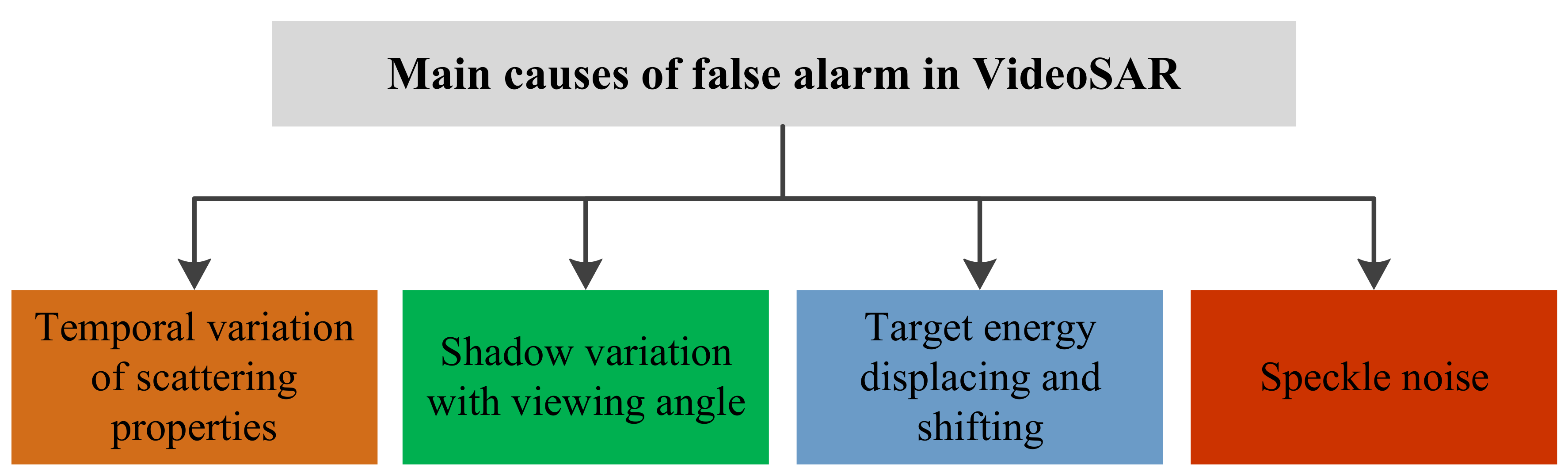
  • FA 1: False alarm introduced by the variation of the scattering characteristics. Due to the slow changing of the features, VideoSAR image sequence will inevitably jitter and cause false alarms.
  • FA 2: False alarm introduced by the change of the viewing angle. The shadow of stationary target (eg: trees alongside the road) also changes with the viewing angle, bringing in some false alarms.
  • FA 3: False alarm introduced by the target defocusing energy return, which regarding as bright spots (or lines) shifting in the video.
In Section 3.1 we come up with the idea of utilizing edge information to reduce false alarm. Nevertheless, edge detection results in Figure 3 (4 binary images) also denote that both false alarms and moving target are overlapping with edge region, which forces us to explore some further edge information.
Here we introduce a mathematical derivation of shadow energy. Supposing k is the Boltzmann constant. T 0 is the effective noise temperature in receiver. B n is the spectrum density of effective noise and F n is the noise coefficients of the receiver. The radar flies with a velocity of V r . And the SNR (Signal-to-Noise Ratio) of the area target is S N R a r e a . Then the target power in SAR image can be given as follows
P t o t a l = k F n T 0 B n 1 + S N R a r e a
For the moving target (right-hand) in Figure 2, the equivalent lengths on range and azimuth direction are L a = L t · c o s θ and L r = L t · s i n θ , respectively. And the corresponding velocities are v a = v t · c o s θ and v r = v t · s i n θ , respectively. Then the total time that a ground scattering point P is shadowed can be written as
T s h a d o w = min L a v a , L r v r
Due to the continuous motion of the target, P is only partly shadowed. Here we define a scale factor q to represent.
q = T s h a d o w T = L t v t 2 ρ a V r r λ c
where T is the synthetic aperture time, r is the nearest range between radar and target, λ c is the carrier wavelength and ρ a is the azimuth resolution.
T s h a d o w = ( 1 q ) T
And the equivalent SNR can be defined as
S N R a r e a _ m = 1 q · S N R a r e a
Finally, we could obtain the moving target power in SAR image via Equations (6) and (10).
P m o v i n g = k F n T 0 B n 1 + S N R a r e a _ m = k F n T 0 B n 1 + 1 q S N R a r e a
Similarly, it is easy to get the power of stationary target and background.
P s t a t i o n a r y = k F n T 0 B n
P b a c k g r o u n d = k F n T 0 B n 1 + S N R a r e a
Comparing Equations (11) and (12), we could figure out that the gray scale difference between the stationary target shadow and the background is much wider than that between the moving target shadow and the background. Notice that the region in where stationary target located is also easily to cause massive false alarms, thus such information can be exploited to improve accuracy of the false alarm reduction in VideoSAR.

4. False Alarm Reduction Method via Gradient-Weighted Edge Information

This section will give a fully introduction of the proposed false alarm reduction method via gradient-weighted edge information. The Sobel operator is introduced to detect the edge of the image for its high edge detection accuracy and low computational load [16].
Figure 4 depicts the calculation principle of gradient in edge region. In case of the edge region between stationary target and background. The derivatives of the direction x (or y) can be calculated as the energy difference between B 1 (or B 2 ) and T, which is
f x = f x + 1 f x = P B 1 P T = P b a c k g r o u n d P s t a t i o n a r y
f y = f y + 1 f y = P B 2 P T = P b a c k g r o u n d P s t a t i o n a r y
Then the gradient of the edge M x , y should satisfy
T i = M x , y = f x 2 + f y 2
It is obvious that M x , y can be used to characterize the intensity of edge. T i can be set to obtain the edge region that meets the specified gradient threshold. By plugging the energy of stationary, moving targets and background into Equations (14) and (15), one could acquire the maximum and minimum thresholds of edge detection (see T h i g h and T l o w ).
Edg e T i x , y = 0 , M x , y < T i 1 , M x , y T i
T i = { T l o w , i = 1 T l o w + i 1 T h i g h T l o w N 1 , 1 < i < N T h i g h , i = N
where N is the total number of edge detection. It is easy to obtain the edge region by a pixel-by-pixel threshold decision. And also one can judge whether it belongs to a real target according to the overlapping area between detected object and edge region.
Assuming ROI ( k ) is an object obtained via pre-detection (procedure that extracts moving regions from stationary background) and Edg e T l o w k is the corresponding edge region around it, S m a x denotes the maximum overlapping area. Then the area of overlapping region S u n w e i g h t should satisfy
S u n w e i g h t = n u m e l ROI k · Edg e T l o w k
where n u m e l ( · ) calculate the total amount of overlapped pixels, · represents the AND operation. Edge region is detected via the lowest threshold to simplify the subsequent normalization. Pre-detected objects who meet the above S m a x criteria will be retained as correct detections and those who do not meet will be removed as false alarms. This method could suppress a lot of false alarms via appropriate edge detection and overlapping area thresholds. But such thresholds are not easy to find, especially the appropriate edge detection threshold. Improper thresholds may cause damaging consequences on detection effect. Hence it is necessary to combine with more information.
According to the analysis in Section 3.2, target shadows will also own edge region with lower gradient, whereas the background edge generally owns higher gradient. So one could get more accurate identification between false alarm and real target based on the edge gradient difference they overlapped with. The process is described in Figure 5.
False alarms which overlap with strong edge region can not be removed via simplex overlapping area criteria. Therefore, the gradient information of the edge is introduced to weight each pixel in the edge region. The gradient-weighted edge overlapping area can be defined as ( s u m · returns the sum of matrix elements)
S w e i g h t = s u m ROI k · Edge k
where Edge ( k ) is obtained by accumulating the edge detection results by multiple thresholds, which is
Edge k = i = 1 N Edg e T i k
where N is the total amount of thresholds for edge detection. Edg e T i is the edge detection result obtained by T i (0 or 1).
In order to obtain a proper threshold, we normalize the gradient-weighted overlapping area S w e i g h t via a division by S u n w e i g h t
η S = S w e i g h t S u n w e i g h t
Equation (22) indicates that the value of Edge k is between 0 and N, which indicates the weight of each edge pixel. More closer to N indicates more times x , y is regarded as edge region and subsequently more possibilities to be a false alarm (red rectangle in Figure 5). η m a x is introduced to remove the false alarm which do not satisfy η S η max .
In summary, the VideoSAR false alarm reduction method via gradient-weighted edge information can be summarized by a flowchart shown in Figure 6.

5. Experiments and Analysis

Experiments on a real VideoSAR footage are carried out to verify the effectiveness of the proposed method. This footage is captured in Kirtland Air Force Base and published by Sandia National Laboratories [2], for which we are thankful. The parameters are set as follow: the footage contains 900 frames and owns a framerate of 29.9 Hz. The pre-detection is explained in Section 2. T h i g h is set to be 9 where stationary target shadow is exactly detected, T l o w is 4 for detecting moving target shadow and N is 3. Edge detection results are dilated by a 2 × 2 circular structure element. S m a x is 0 . 8 · S u n w e i g h t , which means the area of overlapping region should not exceeds 80% of the ROI ’s area. η m a x is 1 . 5 , which means the gradient of overlapped edge region should not be much higher than the edge created by moving target. Figure 7 and Figure 8 shows the processing results of two randomly selected frames (18th and 369th frame). Figure 9 compares the gradient between false alarms and real targets. An adaptive histogram equalization is operated for better visibility (original image is extremely dark and hard to recognize) [17].
Figure 7 and Figure 8 show that both the unweighted (sub-figure (b)) and the gradient-weighted (sub-figure (c)) edge information can be exploited to improve the performance of moving target detection, where the amount of false alarms drops from 10 to 4 after the unweighted method and further to 0 after the gradient-weighted method in Figure 7 and drops from 4 to 2 and further to 0. Meanwhile, all correct detections are retained without any missing detection. It is also worth noticing that all suppressed false alarms occur in edge region, like road edge, stationary target shadow, image border and so forth.
It can be found in Figure 9 that most false alarms emerge in weak scattering area and overlap with the edge region, whereas their overlapping area (background edge) are no more than 0 . 8 · S u n w e i g h t . Thus they can not be removed via a area threshold of overlapping region. Since the moving target shadow also overlaps with edge region, reducing the area threshold will inevitably damage the detection performance. Nevertheless, background edge generally holds higher weights (greater than 1) and regarding as strong edges. Such detected object will not meet the threshold and will be accurately identified and eliminated. Moving targets in the latter 2 rows also see a large overlapping area with edge region. Whereas the gradient are low, their detection results will be preserved.
Sub-figure (a) in Figure 10 shows the variation of the amount of false alarm, where blue bars represent the pre-detection case, green ones represent unweighted edge detection case and red ones represent gradient-weighted case. One could notice that the amount of false alarm drop drastically and some even to 0. Sub-figure (b) are the variation of the amount of correct detection. It can be seen that in most frames, the amount of detection remain stable compared with the original one, which means the proposed method only cause little impact on the detection effect. According to the statistics, the detection rate of this footage can reach a level of 74.8% and the false alarm rate can be as low as 18.4%. It should be noticed that nearly all conventional false alarm methods, like the speckle noise suppression and morphological filtering, did not utilize the spatial distribution feature. Such procedures are all included in the pre-detection module of these experiments.
Table 1 lists out the comparison result of 3 false alarm reduction methods: method via median filtering, unweighted edge information and gradient-weighted edge information. It is obvious that the gradient-weighted edge detection case performs better than other 2 methods on false alarm amount index (2–4 columns). On the detection rate index, the proposed method also produces comparable results with decline in only 2 frames (5–7 columns). Such slight declination may caused by some real targets that happened to move near the road edge.
In a word, the proposed method accurately distinguishes the correct detection and the false alarm via the gradient difference between the target shadow edge and the background edge, enabling more accurate and reliable false alarm reduction results.

6. Conclusions

In this letter, a VideoSAR false alarm reduction method via gradient-weighted edge information is proposed. The gradient-weighted edge information is introduced to remove the false alarm in the edge region to improve the accuracy of moving target detection. The relationship between the shadow defocusing and target velocity is explained and the causes of the false alarm in the edge region is analyzed. The gradient difference between the edge of the target shadow and the edge of the background is also demonstrated. The edge is extracted and weighted by the gradient information to realize an accurate suppression of the false alarm in the edge region. Experimental results obtained by a real VideoSAR footage demonstrate that the proposed method can effectively remove the false alarm in the edge region and improve the accuracy of the detection result and hardly affect the result of the correct detection. The idea that explores the spatial distribution of false alarm can also be utilized on optical/infrared or other sensors data.

Funding

This research received no external funding.

Acknowledgments

The author would like to thank the Sandia National Laboratories of America for providing the real VideoSAR footage and the National University of Defense Technology for supporting the research.

Conflicts of Interest

The authors declare no conflict of interest.

References

  1. Fan, Q.; Chen, F.; Cheng, M.; Lou, S.; Xiao, R.; Zhang, B.; Wang, C.; Li, J. Ship Detection Using a Fully Convolutional Network with Compact Polarimetric SAR Images. Remote Sens. 2019, 11, 2171. [Google Scholar] [CrossRef]
  2. Xu, L.; Zhang, H.; Wang, C. Compact polarimetric SAR ship detection with m-δ decomposition using visual attention model. Remote Sens. 2016, 8, 751. [Google Scholar] [CrossRef]
  3. Xiang, D.; Wang, W.; Tang, T.; Su, Y. Multiple-component polarimetric decomposition with new volume scattering models for PolSAR urban areas. IET Radar Sonar Navig. 2017, 11, 410–419. [Google Scholar] [CrossRef]
  4. William, H.D.; Lloyd, B.D.; Ana, M. A Velocity Independent Continuous Tracking Radar Concept; Sandia National Laboratory (SNL-NM): Albuquerque, NM, USA, 2011.
  5. Jahangir, M. Moving target detection for synthetic aperture radar via shadow detection. In Proceedings of the 2007 IET International Conference on Radar System, Edinburgh, UK, 15–18 October 2007; pp. 16–18. [Google Scholar]
  6. Zhang, Y.; Mao, X.; Yan, H.; Zhu, D.; Hu, X. A novel approach to moving targets shadow detection in VideoSAR imagery sequence. In Proceedings of the 2017 IEEE International Geoscience and Remote Sensing Symposium (IGARSS 2017), Fort Worth, TX, USA, 23–28 July 2017; pp. 606–609. [Google Scholar]
  7. Jahangir, M.; Blacknell, D.; Moate, C.P.; Hill, R.D. Extracting information from shadows in SAR imagery. In Proceedings of the 2007 IEEE International Conference on Machine Vision (ICMV 2007), Islamabad, Pakistan, 28–29 December 2007; pp. 107–112. [Google Scholar]
  8. Wang, H.; Chen, Z.; Zheng, S. Preliminary research of low-RCS moving target detection based on Ka-band video SAR. IEEE Geosci. Remote Sens. Lett. 2017, 14, 811–815. [Google Scholar] [CrossRef]
  9. Yuan, Y.; He, G.; Wang, G. A background subtraction and frame subtraction combined method for moving vehicle detection in satellite video data. J. Univ. Chin. Acad. Sci. 2018, 35, 50–58. [Google Scholar]
  10. Xu, H.; Yang, Z.; Chen, G. A ground moving target detection approach based on shadow feature with multichannel high-resolution synthetic aperture radar. IEEE Geosci. Remote Sens. Lett. 2016, 13, 1572–1576. [Google Scholar] [CrossRef]
  11. Xu, H.; Yang, Z.; Tian, M. An Extended Moving Target Detection Approach for High-Resolution Multichannel SAR-GMTI Systems Based on Enhanced Shadow-Aided Decision. IEEE Trans. Geosci. Remote Sens. 2018, 56, 715–729. [Google Scholar] [CrossRef]
  12. Culibrk, D.; Marques, O.; Socek, D. Neural network approach to background modeling for video object segmentation. IEEE Trans. Neural Netw. 2007, 18, 1614–1627. [Google Scholar] [CrossRef]
  13. Song, X.; Yu, W. Processing video-SAR data with the fast backprojection method. IEEE Trans. Aerosp. Electron. Syst. 2016, 52, 2838–2848. [Google Scholar] [CrossRef]
  14. Liu, B.; Zhang, X.; Tang, K. Spaceborne Video-SAR moving target surveillance system. In Proceedings of the 2016 IEEE International Geoscience and Remote Sensing Symposium (IGARSS 2016), Beijing, China, 10–15 July 2016; pp. 2348–2351. [Google Scholar]
  15. Soumekh, M. Synthetic Aperture Radar Signal Processing; Wiley: New York, NY, USA, 1999. [Google Scholar]
  16. Vincent, O.R.; Folorunso, O. A descriptive algorithm for sobel image edge detection. In Proceedings of the 2009 Informing Science & IT Education Conference (InSITE 2009), Macon, GA, USA, 12–15 June 2009. [Google Scholar]
  17. Zimmerman, J.B.; Pizer, S.M.; Staab, E.V. An evaluation of the effectiveness of adaptive histogram equalization for contrast enhancement. IEEE Trans. Med. Imaging 1988, 7, 304–312. [Google Scholar] [CrossRef] [PubMed]
  18. Attar, A.; Rad, R.M.; Atani, R.E. A survey of image spamming and filtering techniques. Artif. Intell. Rev. 2013, 40, 71–105. [Google Scholar] [CrossRef]
Figure 1. Main causes of false alarm in VIdeo syntehetic aperture (VideoSAR).
Remotesensing 11 02677 g001
Figure 2. Formation of shadow in VideoSAR images. (a) Description of top view (the defocusing energy of moving target is omitted). (b) Description of side view.
Remotesensing 11 02677 g002
Figure 3. Schematic diagram of the false alarms in the edge region. Green rectangles indicate the shadow area of moving targets and red ones indicate some common kinds of false alarms in edge region. Their corresponding edge regions (same detection parameters) are zoomed in for better visibility.
Remotesensing 11 02677 g003
Figure 4. Schematic diagram of the edge region between target shadow and background. Dark gray rectangle represents target shadow and light one is the background. Blocks in green outer contours are 4 adjacent pixels (edge region).
Remotesensing 11 02677 g004
Figure 5. Schematic diagram of the false alarm reduction via gradient-weighted edge information. (a) Description of unweighted edge detection case. (b) Description of gradient-weighted edge detection case. Green rectangle indicates the shadow area of a real moving target, red one indicates the false alarm and other patterns of rectangles indicate the edge detection results with different gradients.
Remotesensing 11 02677 g005
Figure 6. Flowchart of VideoSAR false alarm reduction method via gradient-weighted edge information. Green rectangles highlight the gradient-weighted procedures. Variables beside the arrows are transfered to the next operating block.
Remotesensing 11 02677 g006
Figure 7. False alarm reduction results of the 18th frame. (a) Description of pre-detection result. (b) Description of false alarm reduction result via unweighted edge detection. (c) Description of false alarm reduction result via gradient-weighted edge detection. Red blocks represent detected objects.
Remotesensing 11 02677 g007
Figure 8. False alarm reduction results of the 369th frame. (a) Description of pre-detection result. (b) Description of false alarm reduction result via unweighted edge detection. (c) Description of false alarm reduction result via gradient-weighted edge detection. Red blocks represent detected objects.
Remotesensing 11 02677 g008
Figure 9. Edge detection results of typical (a,b) false alarms and (c,d) real targets. Images in the first row represent unweighted edge detection results and those in the second row represent gradient-weighted edge detection results. Different colors, as legend depicted, refer to different acutances of edge regions.
Remotesensing 11 02677 g009
Figure 10. Statistics of the amount of (a) False alarm. (b) Correct detection. One point is taken every 50 frames for image quality.
Remotesensing 11 02677 g010
Table 1. Statistical results of false alarm amount and detection rate of different false alarm reduction methods. ’Median’ represents median filtering, ’Unweighted’ represents unweighted edge detection case and ’Gradient’ represents gradient-weighted case [18].
Frame NumberFalse Alarm AmountDetection Rate
MedianUnweightedGradientMedianUnweightedGradient
101110.570.570.57
702210.860.860.71
130110111
1901100.511
2500000.50.50.5
310221111
3701110.750.750.75
4304320.750.750.75
5001000.830.830.83
5704520.670.670.67
630310110.8
690310111
7505420.50.50.5
8106630.80.80.8
8703210.670.670.67

