Article

The High-Performance Airborne Imaging Spectrometer HyPlant—From Raw Images to Top-of-Canopy Reflectance and Fluorescence Products: Introduction of an Automatized Processing Chain

by
Bastian Siegmann
1,*,
Luis Alonso
2,
Marco Celesti
3,
Sergio Cogliati
3,
Roberto Colombo
3,
Alexander Damm
4,
Sarah Douglas
5,
Luis Guanter
6,
Jan Hanuš
7,
Kari Kataja
8,
Thorsten Kraska
9,
Maria Matveeva
1,
Jóse Moreno
2,
Onno Muller
1,
Miroslav Pikl
7,
Francisco Pinto
10,
Juan Quirós Vargas
1,
Patrick Rademske
1,
Fernando Rodriguez-Morene
7,
Neus Sabater
2,11,
Anke Schickling
12,
Dirk Schüttemeyer
13,
František Zemek
7,14 and
Uwe Rascher
1
add Show full author list remove Hide full author list
1
Institute of Bio- and Geosciences, Plant Sciences (IBG-2), Forschungszentrum Jülich GmbH, 52428 Jülich, Germany
2
Department of Earth Physics and Thermodynamics, University of Valencia, 46980 Valencia, Spain
3
Remote Sensing of Environmental Dynamics Lab., DISAT, University of Milano-Bicocca, 20126 Milan, Italy
4
Department of Geography, University of Zurich, 8057 Zurich, Switzerland
5
National Physical Laboratory, Teddington TW11 0LW, UK
6
ETSI de Telecomunicación, Universitat Politècnica de València, 46022 Valencia, Spain
7
Global Change Research Institute, Czech Academy of Sciences, 60300 Brno, Czech Republic
8
Specim Spectral Imaging Ltd., 90590 Oulu, Finland
9
Field Lab Campus Klein-Altendorf, University of Bonn, 53359 Rheinbach, Germany
10
International Maize and Wheat Improvement Center (CIMMYT), Ciudad de México 11305, Mexico
11
Finnish Meteorological Institute, 00560 Helsinki, Finland
12
German Aerospace Center (DLR), Space Administration, Earth Observation, 53227 Bonn, Germany
13
ESA-ESTEC, 2201 AZ Noordwijk, The Netherlands
14
University of South Bohemia, 37005 Ceske Budejovice, Czech Republic
*
Author to whom correspondence should be addressed.
Remote Sens. 2019, 11(23), 2760; https://doi.org/10.3390/rs11232760
Submission received: 30 October 2019 / Revised: 15 November 2019 / Accepted: 20 November 2019 / Published: 23 November 2019

Abstract

:
The HyPlant imaging spectrometer is a high-performance airborne instrument consisting of two sensor modules. The DUAL module records hyperspectral data in the spectral range from 400–2500 nm, which is useful to derive biochemical and structural plant properties. In parallel, the FLUO module acquires data in the red and near infrared range (670–780 nm), with a distinctly higher spectral sampling interval and finer spectral resolution. The technical specifications of HyPlant FLUO allow for the retrieval of sun-induced chlorophyll fluorescence (SIF), a small signal emitted by plants, which is directly linked to their photosynthetic efficiency. The combined use of both HyPlant modules opens up new opportunities in plant science. The processing of HyPlant image data, however, is a rather complex procedure, and, especially for the FLUO module, a precise characterization and calibration of the sensor is of utmost importance. The presented study gives an overview of this unique high-performance imaging spectrometer, introduces an automatized processing chain, and gives an overview of the different processing steps that must be executed to generate the final products, namely top of canopy (TOC) radiance, TOC reflectance, reflectance indices and SIF maps.

Graphical Abstract

1. Introduction

Hyperspectral airborne imaging for applications in plant science has a long history and started with the AVIRIS sensor in 1987, which was built by the Jet Propulsion Laboratory of NASA [1]. To date, several comparable sensors have also been developed and used extensively, such as HyMap (HyVista Corp., Australia), APEX (University of Zurich, Switzerland, and Flemish Institute for Technological Research (VITO), Belgium), CASI (ITRES Research Ltd., Canada), Aisa (Specim Ltd., Finland) and HySpex (Norsk Elektro Optikk, Norway). These sensors more or less cover the spectral range from 400–2500 nm with a full width at half maximum (FWHM) of a few nanometers for each single band. Image data acquired by the above-mentioned sensors are very useful because they enable cost-effective and non-destructive assessment of structural (e.g., leaf area index (LAI) and biomass) and biochemical (e.g., pigment and water content) vegetation properties (e.g., [2,3,4,5]).
In addition to reflecting light, plants also emit a small amount of light in the red and near-infrared spectral domain from 670–780 nm. This signal is known as sun-induced chlorophyll fluorescence (SIF). Since SIF is emitted from the core of the photosynthetic machinery, it provides information directly linked to photosynthetic efficiency [6,7]. SIF, therefore, adds complementary information to reflectance-based optical spectroscopy. The complexity of the signal, however, still causes several open points, including the scale dependency of SIF, full understanding of its information content and the way forward to mechanistically exploit SIF for advanced predictions of ecosystem photosynthesis and related gas-exchange processes.
In recent decades, several devices have been developed to measure SIF on leaves at ground (e.g., FluoWat [8]) and canopy level (e.g., FLoXBoX [9]). In addition, data from different atmospheric chemistry satellites, such as GOSAT [10,11,12], OCO-2 [13], GOME-2 [14] and TROPOMI [15,16], have been used to derive SIF at different spatial and temporal scales. These studies have already demonstrated the potential of satellites to measure SIF from space and the importance of this information to better understand the photosynthetic functioning of vegetation. To explore this potential further, the European Space Agency (ESA) selected the FLuorescence EXplorer (FLEX) in 2015, the first satellite solely designed to measure SIF on a global scale, to become ESA’s Earth Explorer 8. FLEX will be operated in a tandem constellation with Sentinel-3 and will deliver landscape- and ecosystem-scale data with a spatial resolution of 300 m [17].
Besides ground- and space-borne platforms, unmanned aerial vehicles (UAVs) and classical aircraft also have the potential to carry sensors measuring SIF at an intermediate spatial scale to close the gap between proximal and satellite measurements. Due to technical limitations, to date, only a few studies have demonstrated the retrieval of SIF from UAV platforms using point spectrometers and small imaging devices (e.g., [18,19,20]). In contrast, airborne-based imaging spectroscopy already provides critical infrastructure to bridge ground- and satellite-based knowledge and technology to detect SIF on canopy scale. In this context, the AirFLEX line scanner was the first airborne instrument used to measure SIF in different campaigns between 2005 and 2008 [21]. The potential of other imaging spectrometers, such as ROSIS [22], CASI-1500 [23], HYPER [21] and APEX [24], was also investigated to measure SIF from airborne platforms. The spectral resolutions of these instruments (2.2–7.0 nm), however, were sub-optimal for SIF retrieval, and only facilitated relative proxies of fluorescence [25].
Motivated by the lack of airborne imaging devices specifically designed to retrieve SIF, and the increasing interest amongst the scientific community in terms of measuring this signal, the HyPlant imaging spectrometer was developed and built by Forschungszentrum Jülich in cooperation with the company Specim Ltd. (Finland) [26]. Over the years, HyPlant has been operated several times, together with a TASI-600 hyperspectral thermal imager (ITRES Research Ltd., Canada) and an LMS-Q780 full-waveform airborne LiDAR (RIEGL Laser Measurement Systems GmbH, Austria), onboard an aircraft from the Global Change Research Institute (CzechGlobe) during different preparatory campaigns for FLEX and other upcoming ESA satellite missions. Simultaneous recording of hyperspectral, thermal and LiDAR data enables the acquisition of a comprehensive set of structural and physiological measurements to facilitate the calculation of ecosystem functions (i.e., GPP and transpiration) and vegetation stress responses.
Since SIF is a very small signal and constitutes only 2%–5% of the reflected light of plants at canopy level, its retrieval from at-sensor radiances is a complicated process. Several issues have been found to compromise SIF-retrieval accuracy, requiring specific processing routines and tools. These include (i) conversion of raw digital measurements to calibrated at-sensor radiance, and compensation for any sensor non-uniformity (i.e., spectral shift or distortions of the point-spread functions); (ii) compensation for atmospheric absorption and scattering effects; (iii) the geolocation of observations; (iv) retrieval of SIF; and (v) retrieval of additional data to facilitate interpretation of SIF and calculation of higher-level products.
An automatized processing chain has been developed in recent years, which enables all these points to be taken into account in a consistent way, so that numerous HyPlant data cubes can be processed in a short space of time, guaranteeing the availability of the processed HyPlant data soon after data acquisition. The aim of this paper is to provide a detailed overview of this processing chain and the processing steps that must be executed to generate the final products from HyPlant DUAL and FLUO raw image data. We describe the HyPlant sensor system and outline the general structure of the processing chain. The individual components of the processing chain are detailed, addressing the challenges listed above. Using an example dataset, we demonstrate the applicability of the implemented processing infrastructure and critically discuss open points and ways forward.

2. Materials and Methods

2.1. HyPlant System

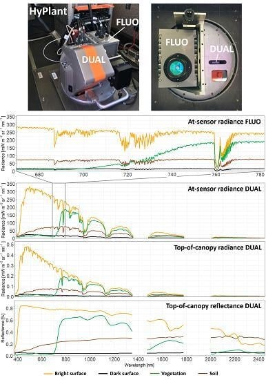
The HyPlant system is a combination of three pushbroom imaging line scanners, aligned and attached to a single mounting plate (Figure 1a). The two line scanners covering the visible/near infrared (VNIR) and shortwave infrared (SWIR) range from 380–2500 nm share the same optic and, together, form the DUAL module. This part of HyPlant is an established airborne imaging platform similar to the Specim AisaFENIX system. The second module (named FLUO and available commercially under the name AisaIBIS) only covers the red and the NIR spectral range between 670 and 780 nm. Due to its high spectral sampling interval (SSI) of 0.11 nm, and fine spectral resolution, of 0.28 nm for the O2-A and 0.29 nm for the O2-B absorption feature, respectively, as well as its high signal-to-noise ratio (O2-A: 296; O2-B: 442) the sensor enables the retrieval of SIF. Both sensors are connected to an Oxford 3052 GPS/INS (Global Positioning System/inertial navigation system) unit (Oxford Technical Solutions Ltd., Oxford, UK), which collects precise and temporal highly resolved navigation and sensor orientation information, which is needed for the geometric correction of the HyPlant image cubes. The HyPlant system was first employed in 2012 and has been continuously upgraded and optimized for accurate SIF retrieval. Table A1 gives an overview of the major technical improvements made in previous years. The system has reached maturity with the version HyPlant 3 and has been purchased by various institutions. Table 1 summarizes the current and consolidated HyPlant 3 system and gives details of its main characteristics.

2.2. HyPlant Processing Chain

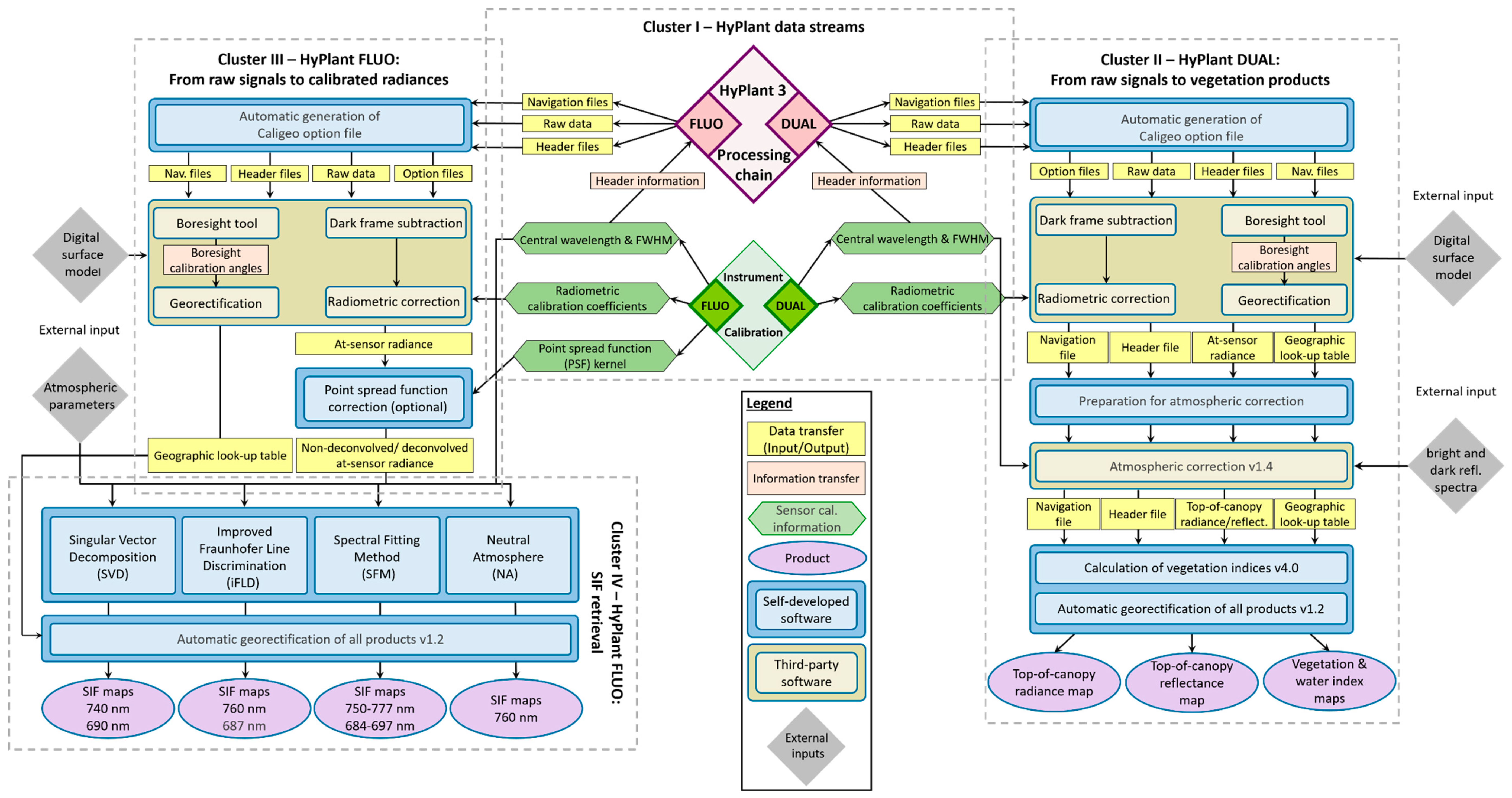
The HyPlant processing chain consists of a number of steps that enable the processing of hyperspectral image cubes recorded by the DUAL and FLUO module from raw data to final products (i.e., top-of-canopy (TOC) radiance and TOC reflectance, reflectance indices and fluorescence maps). The processing chain can be organized into four main clusters. The first cluster describes the transfer of raw data, associated navigation and header files, and calibration data to the two separated processing lines for the DUAL and FLUO module. The second cluster illustrates the processing of DUAL raw data into the final products. The processing of the FLUO data is divided into two clusters. While the third cluster describes the processing from FLUO raw data up to at-sensor radiance, in the fourth cluster, four different SIF-retrieval methods are described, which can be used to generate SIF maps. The following sections provide a detailed overview of the different processing clusters, which, together, constitute the complete HyPlant processing chain (Figure A1).

2.2.1. HyPlant Data Streams—Processing Cluster I

The first cluster is illustrated in Figure 2, which provides an overview of the data stream of both sensors and the navigation data of the Oxford RT3052 GPS/INS unit to the subsequent processing clusters. Each sensor’s data stream consists of the raw image cube in the ENVI ’band interleaved by line’ (BIL) format and the associated header file containing information on the data format, and the GPS start and stop time of the recorded dataset. Besides this, corresponding navigation information from the GPS/INS unit (including time, latitude, longitude, altitude and sensor orientation) is transferred to the second and third processing cluster. Furthermore, important sensor calibration information, determined in the calibration facilities of the sensor manufacturer (e.g., information on central wavelength position, FWHM, radiometric calibration coefficients and point-spread function (PSF) kernel (FLUO only)), are forwarded for further processing.

2.2.2. HyPlant DUAL: From Raw Signals to Vegetation Products—Processing Cluster II

The second processing cluster consists of different steps that describe the processing from HyPlant DUAL raw data to the final products, namely, TOC radiance, TOC reflectance and reflectance index maps (Figure 3). The first processing step in this cluster involves CaliGeoPro software, developed by the sensor manufacturer Specim. To enable automized processing of numerous DUAL image cubes, a software tool based on IDL (Harris Geospatial Solutions Ltd., USA) was developed to carry out batch processing. This software generates an option file containing all the necessary information relating to a data cube (e.g., in- and output directory, location of the radiometric calibration file and the sensor’s field of view). This file, together with the raw data, header information and navigation file, is subsequently transferred to CaliGeoPro.
CaliGeoPro is then used to perform the radiometric correction and to generate a geographic lookup table (GLT) file, which allows the geometric correction of the image cube. The radiometric correction consists of two steps. Firstly, dark frame correction is conducted. On completion of data acquisition for an image cube, the shutter of the sensor is closed for five seconds to record some image lines containing only the dark current noise of the sensor. This noise is then linearly subtracted from each image line, and the dark frame is truncated. Secondly, the radiometric correction file (containing the central wavelength positions and associated radiometric correction coefficients for each pixel on the sensor array) is used to convert the digital numbers (DNs) to at-sensor radiance (mW m−2 sr−1 nm−1).
In parallel, a CaliGeoPro built-in tool is used to calculate the boresight angles. The boresight effect is caused by slight differences in the locations of imaging sensors and the GPS/INS unit in the aircraft. To correct for this effect, the displacement vectors of different devices and associated boresight angles must be determined [27]. To assess the angles, a boresight calibration flight must be conducted once during a campaign, consisting of three flight lines in a triangular pattern with three overlapping regions over an area with ground control points (GCPs). Using this information and an additional digital surface model (DSM) of the area, the boresight tool within CaliGeoPro can estimate the boresight angles by minimizing the difference between the coordinates of the GCPs and the projected coordinates of the same points in the image cube [28,29]. Afterwards, the boresight angles, together with the navigation file containing information on sensor position and orientation for each line of an image cube, are used to generate the GLT file. Applying the GLT file to the image cube removes the aircraft waving effects and calculates ground coordinates for each image pixel [30]. Thus, it is possible to compute a georectified and georeferenced HyPlant DUAL dataset providing at-sensor radiance information. The at-sensor radiance spectra of selected HyPlant DUAL pixels are illustrated in Figure 1b.
Besides this first intermediate result, the non-georectified at-sensor radiance, together with the GLT, header and navigation file, is transferred to the second part of the HyPlant DUAL-processing cluster, which describes the atmospheric correction and subsequent generation of the final products. Like the batch-processing within CaliGeoPro in the previous step, here, a software tool (automatic HyPlant processing tool) was developed in IDL, which enables the processing of numerous data cubes at once.
The commercial software ATCOR-4 (Atmospheric and Topographic CORrection algorithm, ReSe Applications GmbH, Switzerland) [31] is used for the atmospheric correction of the DUAL data. ATCOR-4 is based on MODTRAN5 (MODerate resolution atmospheric TRANsmission) [32] and uses LUTs (lookup tables) in order to accelerate the atmospheric correction. For the atmospheric correction of an image cube, the non-georectified at-sensor radiance image file must be available in ’band sequential’ (BSQ) format, and an input file has to be generated, containing flight altitude, mean ground elevation and the heading of the aircraft. Further, the coordinates, acquisition date and time of the image cube are required to calculate the solar geometry (zenith and azimuth angle). All this information is automatically extracted from the navigation and header file of the image cube and added to the ATCOR-4 input file. Furthermore, additional settings like the aerosol type and spectral region used for the water vapor algorithm need to be selected before ATCOR-4 can perform the atmospheric correction. Since several flight lines acquired from one test site during an airborne campaign have similar atmospheric conditions, the same aerosol model and spectral region for water vapor retrieval can be chosen within the batch process. ATCOR-4 also enables detection of the spectral smile effect. This is an artifact in the data of pushbroom sensors like HyPlant, which is caused by the sensor entrance slit, and leads to a shift in the center wavelength of the spectral bands in the across-track direction [33]. A further option in ATCOR-4 allows the running of an inflight radiometric calibration to be performed. During this process, ground reflectance spectra of bright and dark targets are compared to the corresponding image pixels to determine radiometric calibration coefficients, which can be used to improve the results of the atmospheric correction results [34].
Finally, the determined smile effect for each spectral band, the generated input file and the inflight calibration coefficients are used to run the atmospheric correction of the image cube. As two of the main results, the user receives TOC radiance and TOC reflectance. Afterwards, spectral polishing can be applied to the data, to remove spectral artifacts before the spectral smile interpolation is conducted to correct the data for this spectral misregistration effect. Figure 1c,d illustrate the TOC radiance and TOC reflectance of selected HyPlant DUAL pixels.
Based on the TOC reflectance product, several reflectance indices are additionally calculated, using another IDL sub-tool that can be run in batch mode. The indices are related to leaf area index (LAI) and chlorophyll content (e.g., NDVI, EVI, MTCI and TCARI), photosynthesis and non-photochemical quenching (PRI, cPRI), and canopy water content (WBI). A comprehensive list of all indices and their calculation can be found in Table A2.
As the last step in the second processing cluster, the GLT file generated in CaliGeoPro is used to produce georectified and georeferenced maps of TOC radiance, TOC reflectance and indices. Figure 3 shows some result maps of the HyPlant DUAL processing.

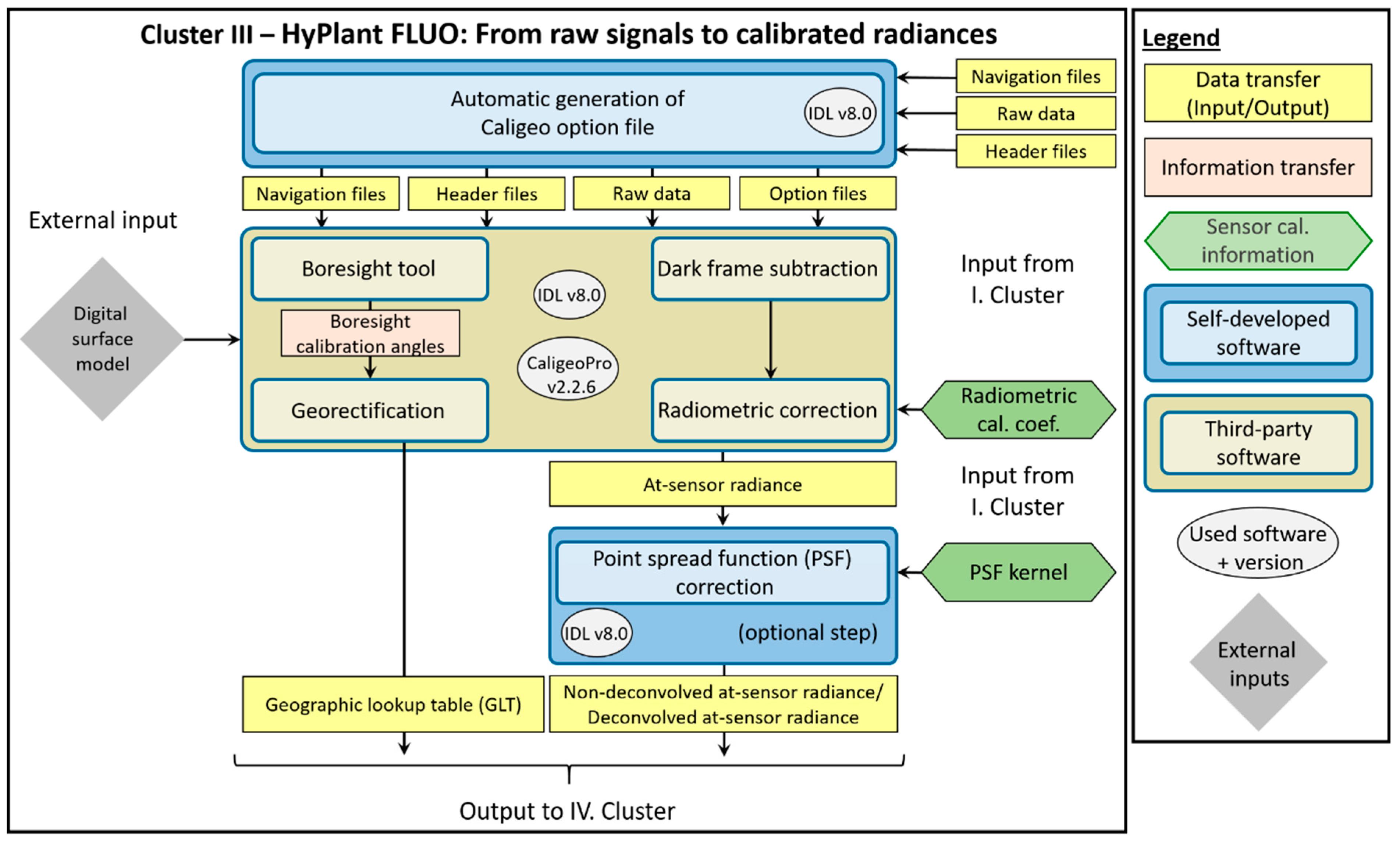
2.2.3. HyPlant FLUO: From Raw Signals to Calibrated Radiances—Processing Cluster III

The third cluster of the HyPlant processing chain describes the procedure of converting FLUO raw data to non-deconvolved/deconvolved at-sensor radiance (Figure 4). For this purpose, the CaliGeoPro software is used again, to perform the same processing steps already described for the DUAL data. This includes the dark frame subtraction and the radiometric correction of the image cube, as well as the boresight correction and the generation of the GLT file for the geometric correction. As the result of this process, the user receives the at-sensor radiance and the GLT file similar to the DUAL processing.
In contrast to the DUAL module, the radiometric correction of the FLUO module can optionally be extended by the application of the PSF deconvolution. Ideally, an imaging spectrometer looking at a monochromatic point source should produce a single pixel response. In real systems like the HyPlant FLUO module, this is not the case, and the resulting signal spreads in the sensor matrix around this pixel. This distribution of light across the sensor (spatial cross-talk) is called “point-spread function” (PSF). For imaging spectrometers, the dimension of the sensor array corresponds to the spatial domain and the second dimension to the spectral domain. Smooth spectral signals are not significantly affected by (although not immune to) the PSF. However, when a spectrum presents neighboring bands with contrasting values (e.g., when absorption features or narrow emission peaks are resolved), the result is a transfer of energy between them, which causes the high signal to decrease and the low signal to increase. This leads to a distinct distortion of the shape and values of the spectrum. The same occurs in the spatial dimension at edges between contrasting targets. Furthermore, the effect can show diagonal contributions between the spectral and spatial signals. Given this, the number of diagonal elements contributing to the effect can be very large. This is especially important for discriminating a weak signal over a bright background, such as in the retrieval of SIF from HyPlant FLUO data.
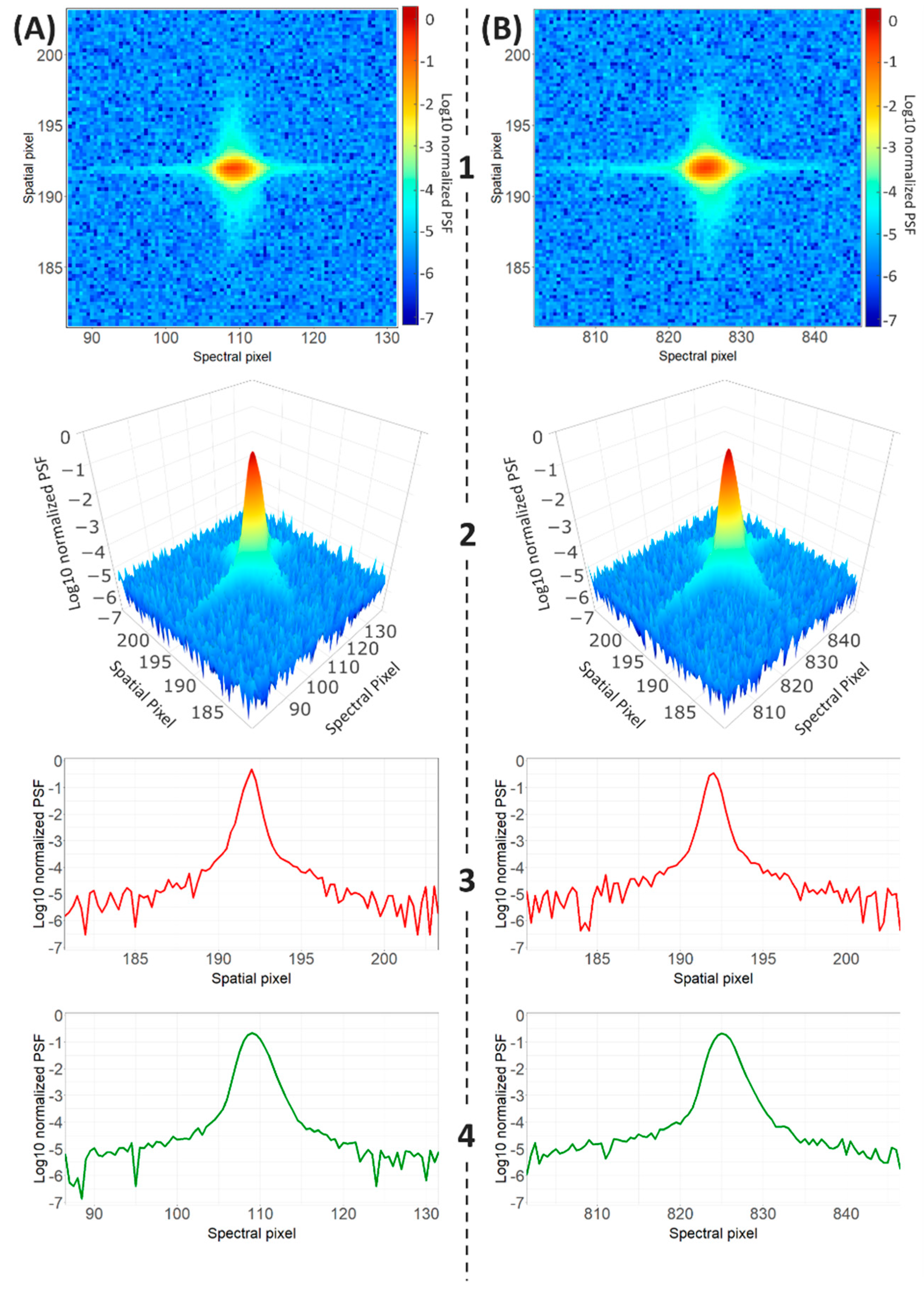
To correct for the above-mentioned effect, PSFs of the FLUO module were characterized in a laboratory by the sensor manufacturer at six wavelengths across the range of the sensor (680, 700, 720, 740, 760 and 775 nm) and at five positions within its field of view (spatial pixel 10, 96, 192, 288 and 374). Figure 5 illustrates two PSFs located in the center of the sensor array in the spatial domain (spatial pixel 192), and close to the oxygen absorption features at 680 and 760 nm in the spectral domain.
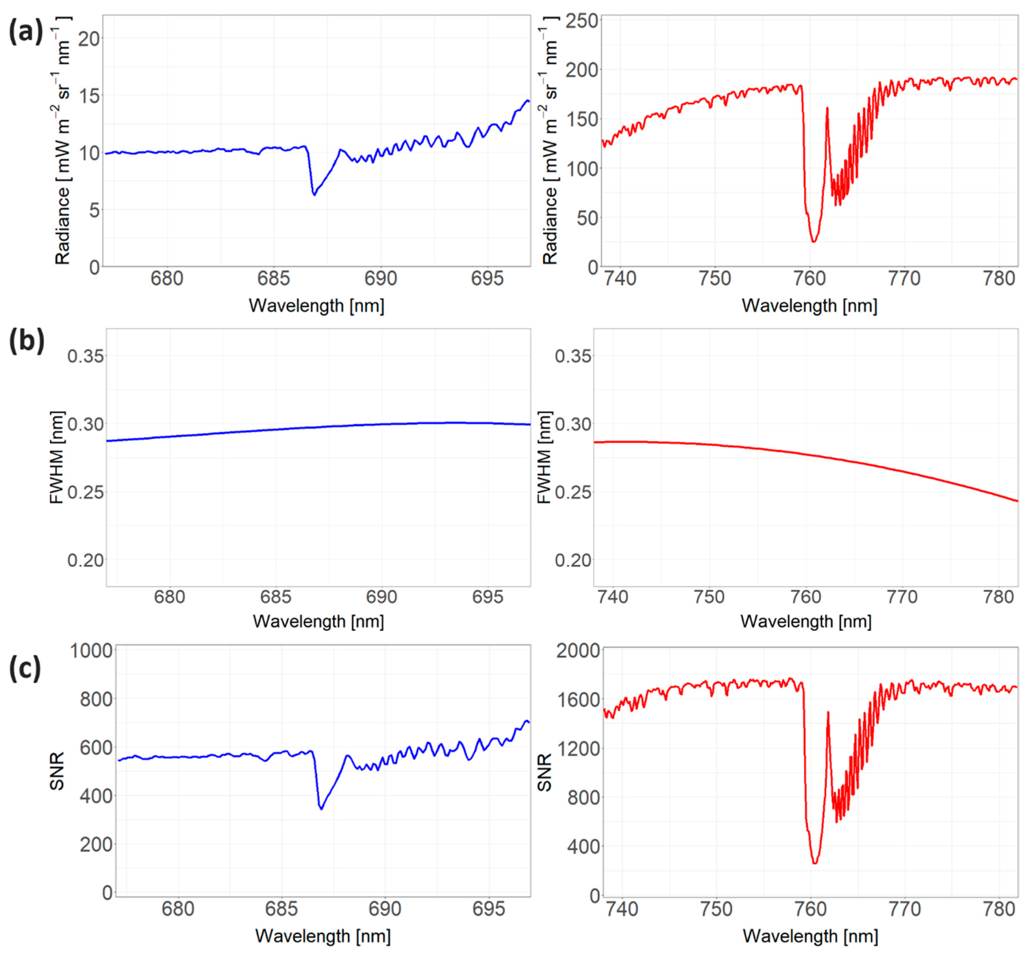
Since the 30 determined PSFs show very similar shapes and values, it is possible to apply the same deconvolution algorithm to the entire image cube. The deconvolution follows the van-Cittert approach, which is explained in [35]. This iterative process results in an image with less stray light at each step, although, if the iteration is not stopped at a proper level, the stray light might not be completely removed or might even result in overcorrection, depending on the radiometric resolution and noise level of the acquired image cube. After processing numerous image cubes, however, it became clear that only one iteration within the deconvolution process tended to yield the best results. Figure 1c shows the at-sensor radiance spectra of selected surfaces after the deconvolution algorithm was applied, whereas Figure 6a focuses on the at-sensor radiance of vegetation zoomed in on the O2-A and O2-B absorption features that are used to retrieve SIF. Moreover, the FWHM and signal-to-noise ratio (SNR) of HyPlant in the two oxygen absorption features are displayed in Figure 6b,c, respectively.

2.2.4. HyPlant FLUO: SIF Retrieval—Processing Cluster IV

The fourth cluster of the HyPlant processing chain deals with the SIF retrieval, based on the non-deconvolved/deconvolved at-sensor radiance of the FLUO data produced in the previous cluster, and is illustrated in Figure 7. The different SIF-retrieval algorithms are applied to non-georectified and non-georeferenced image cubes. The GLT file is only applied at the end (after SIF retrieval has been conducted) to georectify the SIF maps.
The terrestrial oxygen absorption features, located at 760 (O2-A) and 687 nm (O2-B), were mostly used to quantify the SIF signal. Over the years, different approaches have been developed, namely 3FLD [36], cFLD [37], eFLD [38] and iFLD [39], which are all based on the Fraunhofer line discriminator (FLD) principle [40,41] and determine SIF using one spectral band inside and one outside the absorption feature. Whereas FLD-based methods only allow the determination of SIF at a specific wavelength, spectral fitting methods provide quantitative SIF information for all spectral bands within the oxygen absorption features by using a curve-fitting algorithm (e.g., [42]). Alongside methods using the atmospheric oxygen-absorption bands, different approaches based on solar absorption features have been developed, which are independent of atmospheric modeling and can be distinguished in simplified physical schemes (e.g., [43]) and data-driven statistical approaches (e.g., [10]). Comprehensive reviews of the different SIF-retrieval techniques developed in recent decades can be found in [6,25,44].
In total, four different SIF-retrieval methods are implemented in the HyPlant processing chain, namely Singular Vector Decomposition (SVD), Improved Fraunhofer Line Discrimination (iFLD), Spectral Fitting Method (SFM) and Neutral Atmosphere (NA). The main difference between the SIF- retrieval methods is how they compensate for atmospheric effects, disentangle both the reflected and emitted radiance flux, and accommodate sensor non-uniformities (e.g., spectral shift and SNR). The SVD method is based on a statistical approach and allows an estimation of atmospheric impact from singular vectors. For the remaining three SIF-retrieval methods, different approaches of atmospheric correction have been developed. In the following sections, the different methods are explained in detail.

Singular Vector Decomposition (SVD)

The so-called Singular Vector Decomposition (SVD) retrieval method is a form of spectral fitting method for fluorescence retrieval [10,14,45]. It also represents the at-sensor radiance as the sum of the radiance reflected by the surface and the fluorescence contribution. The reflected radiance is constructed as the product of a spectrally smooth surface reflectance (modeled as a polynomial in wavelength) and the atmospheric absorption. However, instead of using explicit radiative transfer modeling to calculate atmospheric absorption along the spectral fitting window, this is modeled as a linear combination of orthogonal spectral functions derived from the data through Singular Vector Decomposition (similar to Principal Component Analysis).
The forward model M used by the SVD method to fit the at-sensor radiance spectrum can then be expressed as:
M ( a i , α j , F ) = μ s I o π [ i a i λ i j α j u j ] + F h f τ e f f
where M describes the spectral radiance received by the sensor over a fluorescent target; μ s is the cosine of the sun zenith angle; I o is the extraterrestrial solar irradiance; λ is the array of wavelengths within the fitting window; υ is the set of singular vectors representing atmospheric absorption; a and α are arrays of weights for the λ and α vectors; F is the fluorescence intensity; h f is the spectral shape of fluorescence; and τ is an effective upward atmospheric transmittance calculated for the flight altitude and convolved to HyPlant’s spectral response function.

Improved Fraunhofer Line Discrimination (iFLD)

The iFLD, as part of the HyPlant processing chain, is based on the iFLD method initially proposed by [39], but was adapted to allow SIF retrievals from HyPlant, in particular, the FLUO module [46]. As implemented, both telluric oxygen absorption bands centered around 687 nm (O2-B) and 760 nm (O2-A) are exploited, yielding SIF retrievals at these two wavelengths.
The main retrieval challenge involves disentangling the emitted SIF radiation from the reflected radiance. Therefore, two measurements inside ( i ) and outside ( o ) of an absorption band are required. The radiative transfer, describing the radiance signal measured at the airborne sensor L λ A t S at these two wavelengths ( λ ), can be described as a function of the extraterrestrial irradiance ( E j 0 ), several atmospheric transfer functions, the surface reflectance ( R ), and the SIF emission ( F ), and can be expressed as:
L λ A t S =   E λ 0 cos θ i l π [ ρ s o λ + ( τ s s λ τ o o λ + τ s d λ τ o o λ + τ s s λ τ d o λ + τ s d λ τ d o λ ) R λ 1 R λ ρ d d λ ] + F λ ( τ o o λ + τ d o λ ) 1 R λ ρ d d λ
where θ i l is the illumination zenith angle; ρ s o is the path scattered radiance; τ s s is the direct transmittance for sunlight; τ o o is the direct transmittance in the view direction; τ s d is the diffuse transmittance of the atmosphere for sunlight; τ d o is the hemispherical–directional transmittance in the view direction, and ρ d d is the spherical albedo.
All required atmospheric transfer functions are obtained from MODTRAN5 [32] simulations, in combination with the MODTRAN5 interrogation technique [47,48,49,50]. Four unknowns remain in Equation (2), namely R and F , inside and outside the O2-absorption band, respectively. The iFLD-based retrieval relates R and F inside and outside both absorption bands using non-linear functions. This step reduces the number of unknowns to two and, given the fact that two L λ A t S measurements are considered, yields a solvable set of equations to eventually retrieve F (cf. [24] for details).
For the airborne data, an empirical constraint based on non-vegetated reference surfaces is additionally implemented to account for uncertainties in the characterization of the atmosphere and remaining sensor artifacts (i.e., spectral shifts and detector mis-calibration). Details of this approach can be found in [51]. The empirical correction yields precise SIF retrievals at 760 and 687 nm but limits the applicability of the method to flight lines with sufficient non-vegetated reference pixels across track along the whole flight line.

Spectral Fitting Method (SFM)

The SFM retrieval algorithm developed for HyPlant is inspired by the original version, proposed by [52,53], and successive improvements by [54,55]. The SFM is a quasi-physical approach, which consists of two main components: (i) atmospheric radiation transfer modeling; and (ii) decoupling reflectance and fluorescence based on the Spectral Fitting technique. The atmospheric spectra are computed by means of MODTRAN5, in which the model input parameters are derived from sun photometer measurements (i.e., aerosol optical thickness (AOT) at 550 nm, water vapor column (WVC) and surface pressure) and geometry parameters derived from the navigation data of a HyPlant image cube. The Spectral Fitting uses general mathematical functions to model the canopy fluorescence and reflectance at different wavelengths within spectral windows centered on the oxygen absorption features (750–780 nm for the O2-A and 684–697 nm for the O2-B feature, respectively). Specifically, the retrieval algorithm employs the Lorentzian function to model the fluorescence emission peak and polynomial or piece-wise cubic splines to fit the reflectance. These two canopy contributions are combined and propagated through the atmosphere according to Equation (3) in order to simulate the at-sensor radiance observed by HyPlant. A comprehensive description of Equation (3) can be found in [54,56], but some details are reported here for clarity.
L   = t 1 [ t 2 + t 8 r s o +     t 9 + t 14 r s d ¯ 1 r d d ¯   t 3 r d o + t 10 r s d ¯ + t 11 r d d ¯ 1 r d d ¯   t 3 ] + t 6 F s o +   [ F h e m ¯ ( t 7 + t 13 r d o ) 1 r d d ¯   t 3 ]
The terms t i represent the atmospheric transfer functions, obtained by combining different atmospheric functions in high resolution and convolving them to the instrument spectral response. The reflectance is modeled by four BRDF terms: r s o is the target bi-directional reflectance factor; r d o is the target directional reflectance for diffuse incidence; r s d ¯ is the average surroundings diffuse reflectance for solar irradiance; r d d ¯ is the average surroundings diffuse reflectance for diffuse incidence. F s o is the sun-induced fluorescence radiance of the target in the observer’s direction, and F h e m ¯ is the hemispherical fluorescence flux of the surroundings. Currently, Equation (3) is employed under the Lambertian assumption for both reflectance and fluorescence, and therefore the different reflectance ( r s o ,   r d o ,   r s d and r d d ) and fluorescence ( F s o and F h e m ) terms are considered equal.
The fluorescence and reflectance are estimated using a numerical optimization technique by comparing the at-sensor radiance computed by Equation (3) and HyPlant observations until the best match is found between the two spectra.

Neutral Atmosphere (NA)

The NA retrieval algorithm is based on the implementation of different steps running in sequence, which are dedicated to (1) refining the instrumental spectral response function (ISRF) through the determination of the spectral shift and band-broadening; (2) correcting the acquired image from the atmospheric effects by applying a classical atmospheric correction scheme [57]; and (3) applying a fluorescence-retrieval strategy at TOC. In this particular case, the NA module includes the SFM [54], initialized by the peak-height method proposed by [58].
The atmospheric correction implemented in the NA strategy makes use of MODTRAN5 lookup tables previously computed. As with the SFM module described above, the model input parameters are derived from sun photometer measurements and the navigation data of a HyPlant image cube. The NA method models the at-sensor acquired radiance following Equation (4), which assumes a Lambertian behavior of the surface reflectance, an isotropic fluorescence emission and considers successive reflectance contributions until second order.
L λ A t S =   L 0 + ( E d i r c o s θ i l + E d i f ) ( T d i r + T d i f ) π ρ a p p + ( E d i r c o s θ i l + E d i f ) ( T d i r + T d i f ) S π ρ a p p 2
In Equation (4),   L 0 is the path radiance; E d i r and E d i f are the direct and diffuse terms of the solar irradiance at surface level;   T d i r and T d i f are the upward direct and diffuse transmittance components; S is the spherical albedo; and ρ a p p is the surface reflectance, accounting for the added normalized contribution of the fluorescence emission. The series expansion is assumed here to avoid the division with the convolved spherical albedo term S ( t 3 in Equation (3) and ρ d d λ in Equation (4). See more details of this approximation in [59].
After atmospheric correction, a novel retrieval approach based on the height of the peaks in the apparent surface reflectance ( ρ a p p ) provides estimates of fluorescence without making any assumption about the shape of the true reflectance [58], being the retrieval limited to bands inside strong absorption features. However, fluorescence estimates from these bands are sufficient for initializing the SpecFit numerical optimization routine from a value closer to the best solution, thus reducing the computation time.

2.3. Example Data

In this section, selected outputs of the HyPlant data processing are presented to give a visual impression of the quality of the final results of both processing chains. For this purpose, a dataset acquired during the 2018 ESA FLEXSense campaign was selected. The main aim of this FLEX preparatory campaign was to collect high-resolution airborne measurements of TOC reflectance and SIF across representative European monitoring sites, accompanied by ground-based measurements of important vegetation and atmospheric properties in parallel to Sentinel-3 satellite overpasses. A Cessna Grand Caravan (C-208 B) operated by CzechGlobe served as the airborne carrier for HyPlant during the entire campaign period from 10 June until 2 August.
The presented dataset was recorded on 29 June 2018 at 12:30 MEST and covers a part of the agricultural research station Campus Klein-Altendorf (CKA), which is affiliated to the Agricultural Faculty of the University of Bonn (Germany). The area is located between the cities of Rheinbach and Meckenheim in the western part of Germany (50°37′N, 6°59′E), 40 km south of Cologne. CKA comprises 181 ha for field trials and approximately 4800 m2 for greenhouse trials. Here, research can be conducted with all kinds of plants and crops, ranging from small plants or herbs to large crops like maize, and from annual crops like vegetables to perennial plants like miscanthus or fruit trees.
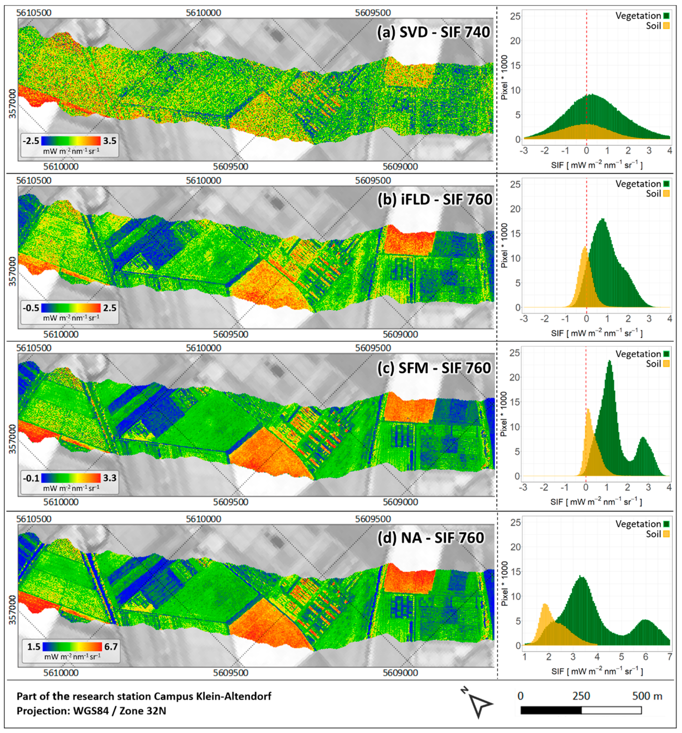
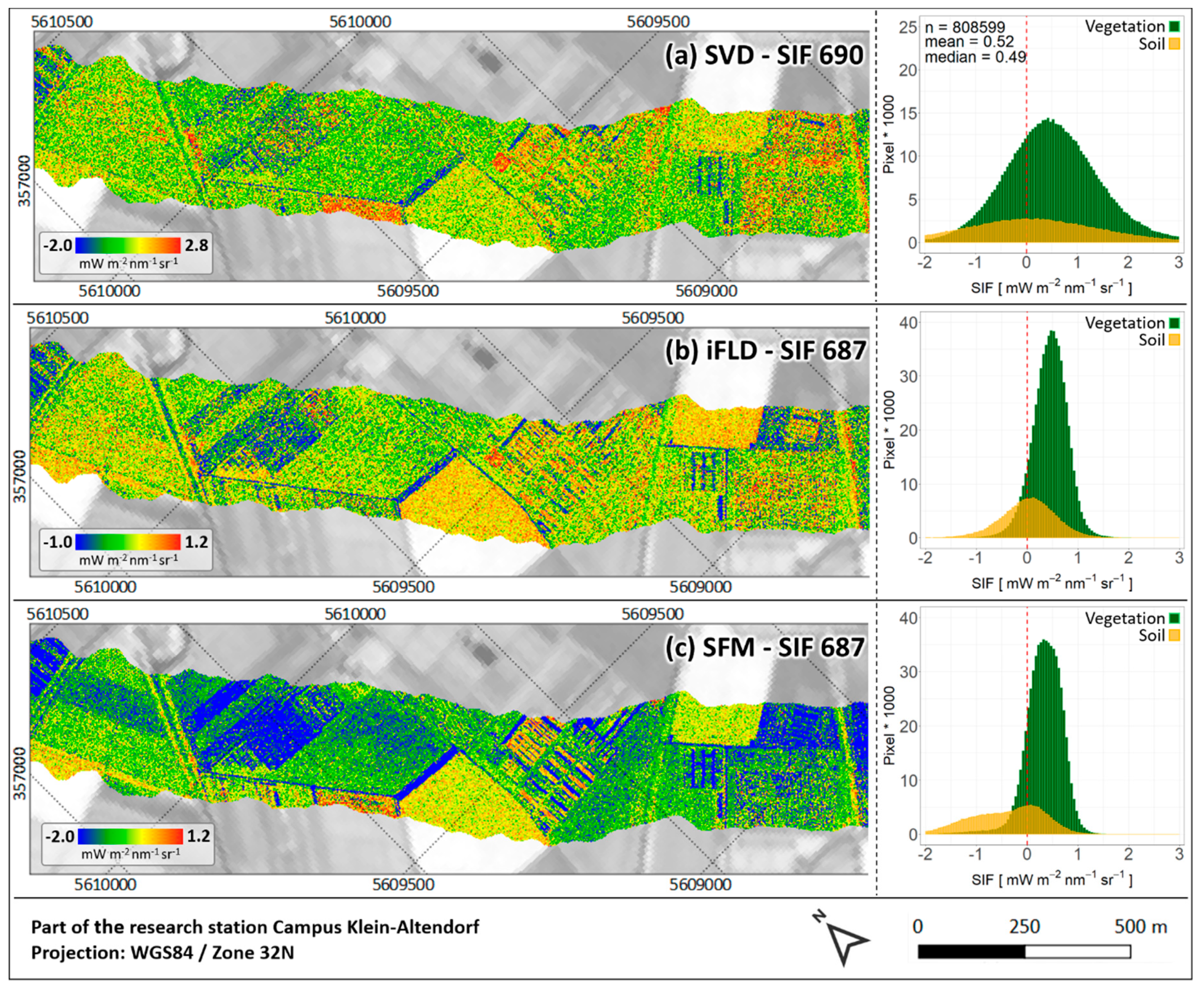
The dataset was recorded 680 m above ground level (agl), which corresponds to a ground sampling distance (GSD) of 1 m for HyPlant. Figure 8, Figure 9 and Figure 10 show selected processing results of both sensor modules. A true-color composite of HyPlant DUAL TOC reflectance and three derived reflectance indices (NDVI, cPRI and WBI) are depicted in Figure 8a–d. In addition, Figure 9 and Figure 10 show the final SIF products and value distributions derived from HyPlant FLUO data, using the four different retrieval methods for the O2-A and O2-B absorption feature, respectively.
The entire HyPlant data set presented in this study is available in form of a data publication in the electronic Data Archive Library (e!DAL) [60] and can be downloaded using the following link [61].

3. Discussion

The HyPlant imaging spectrometer is the first airborne system combining a conventional hyperspectral VNIR/SWIR module (DUAL) with an additional spectrally ultra-highly resolved fluorescence module (FLUO) that enables the retrieval of SIF. In order to process the raw images from both modules into final products, a customized processing chain has been developed in recent years.
Due to the increasing availability of pushbroom airborne imaging systems covering the spectral range from 400–2500 nm with an FWHM of a few nanometers, processing using the DUAL module has now become an almost standard procedure, mainly based on commercial software. The entire workflow comprises three main processing steps: radiometric, atmospheric and geometric correction. These are established procedures and have been reported several times for comparable sensors (e.g., [31,62]). The strength of the HyPlant DUAL imaging spectrometer is the automated connection of the different processing steps, which facilitates the processing of a high number of data cubes in a short space of time.
The HyPlant DUAL processing has already led to high-quality TOC radiance and TOC reflectance maps for flat terrain areas (cf. Figure 1e,f; Figure 8) and is currently being expanded by the integration of a digital elevation model (DEM). This is useful to further improve the aforementioned products, particularly in mountainous regions. The implementation of a newer version of the ATCOR-4 software is, therefore, planned, which makes it easier to consider the relief of an area within the bidirectional reflectance distribution function (BRDF) correction as part of the atmospheric correction of HyPlant DUAL data [34]. Since a DEM or DSM is already used for the boresight correction and generation of GLT files for both sensor modules within the CaliGeoPro software, this information is available and only needs to be transferred to ATCOR-4.
Alongside the main products of HyPlant DUAL processing, ATCOR-4 generates some by-products during the atmospheric correction of an image cube, which contain valuable information that can be useful in other parts of the DUAL and FLUO processing. Differentiated spatial information on AOT and WVC of the atmosphere are, for example, beneficial input data for the SIF retrieval from the FLUO module using the SFM and NA methods. ATCOR-4 provides this information in the form of an AOT map derived at 550 nm and a map showing the spatial WVC distribution within the recorded scene. The use of this information for the SIF retrieval provides an insight into current atmospheric conditions on pixel level, whereas standard atmospheric measurement devices normally record the same information only at stationary locations, with a lower spatial resolution.
Further by-products of ATCOR-4 are the so-called value-added products, which give information about the LAI, the fraction of absorbed photosynthetically active radiation (FPAR) and an albedo value for every pixel in a HyPlant dataset. LAI and FPAR are particularly important for studies related to plant science. In addition, the LAI product delivered by ATCOR-4 can be integrated into the calculation of the canopy photochemical reflectance index (cPRI), which is already one of the indices calculated from HyPlant DUAL TOC reflectance data (cf. Figure 8c). Table A2 shows the equation to calculate the cPRI, where the simple ratio (SR) index is currently used as an approximation of LAI.
Besides the already implemented calculation of reflectance indices related to important plant properties, another goal for the future is to directly invert physically based radiative transfer models (RTMs), making use of the entire spectral data space of HyPlant DUAL. In this context, the ARTMO toolbox [63,64] is a powerful software package, providing access to different canopy RTMs, such as PROSAIL [2], which can be used to derive biophysical and chemical vegetation parameters from HyPlant DUAL TOC reflectance data.
In contrast to the DUAL data processing, the processing of the FLUO data required the adjustment of available and the development of specific new software tools. Since SIF is a very small signal, the following aspects have been considered in the processing of HyPlant FLUO data, in order to allow for an accurate SIF retrieval:
(i) A precise sensor calibration (radiometric calibration, wavelength calibration and FWHM determination) is of the utmost importance for the conversion of DNs to at-sensor radiance values, which form the basis for the subsequent SIF retrieval. As reported in different studies (e.g., [51,65]), a sensor miscalibration (e.g., spectral shift) can lead to systematic and random SIF-retrieval errors. Furthermore, to correct for the effect of spatial and spectral cross-talk caused by the dispersion of light across the sensor matrix, the precise characterization of the sensor’s PSF is an essential step. Different PSF deconvolution approaches have recently been tested to investigate their impact on the FLUO at-sensor radiance quality and the final SIF products. This is part of ongoing research, yet to be published. An initial comparison of HyPlant SIF products derived from deconvolved and non-deconvolved at-sensor radiance by [66], however, has clearly shown the impact of the PSF on the SIF retrieval.
(ii) The accuracy of the SIF retrieval is also strongly affected by atmospheric absorption and scattering effects [14,67]. For this reason, the availability of measurements such as AOT, WVC and surface pressure, describing the atmospheric conditions at the time of a HyPlant overpass, is a crucial factor. This is particularly important for the SFM and NA SIF retrieval, since both methods require the aforementioned atmospheric parameters as input data for the radiative transfer modeling. The sensor surface distance (optical path length) is another important parameter, which has a high impact on the SIF retrieval and thus needs to be considered. While an average surface sensor distance is currently used, it is planned to include elevation information in the form of a DSM in the SFM SIF-retrieval scheme. This will be particularly helpful in rugged terrain to improve the quality of the derived SIF products.
(iii) Another important aspect, addressed in the processing of HyPlant FLUO (and also DUAL) data, is the precise geometric processing of the final products. The positioning and orientation information recorded by the Oxford GPS/INS unit in parallel to the HyPlant data acquisition are used for the geometric correction of both sensor modules. This led to a precise internal image geometry and a high absolute positional accuracy, with only minor deviations of less than ±2 pixel (cf. Figure 8, Figure 9 and Figure 10). In order to further enhance the positional accuracy, a high-resolution RGB snapshot camera has been operated in the aircraft together with HyPlant in recent years. The spatially highly resolved and precisely located image data recorded by this camera will be used in the future to improve the absolute geometric accuracy using different feature-detection and image-matching techniques, such as the scale invariant feature transform (SIFT) and speed up robust feature (SURF) methods [68].
(iv) The four SIF-retrieval schemes implemented in the HyPlant processing chain for the first time allow a cross-comparison of the different methods on a spatially larger scale and can help to identify which approach performs best under certain conditions. In this context, the quality assessment of the HyPlant FLUO products is another important topic, which would support the quantitative comparison of the results provided by the different SIF-retrieval methods. While radiance and reflectance measurements of several homogeneous surfaces on the ground (collected with field spectrometers) can be used to validate the HyPlant DUAL TOC radiance and reflectance products, the quality assessment of the SIF maps derived from HyPlant FLUO data remains a considerable challenge. Due to the limited availability of SIF-measurement devices on the ground and the fast-changing SIF emission of vegetation within a short period of time, to date, only a few studies have been able to perform a validation using SIF measurements collected in parallel to a HyPlant overpass [46,69]. To conduct a quality assessment of the HyPlant SIF maps without having ground truth data available, a set of quality criteria was defined within the framework of the ESA HYPER project. [70] have recently demonstrated the benefits of applying the different criteria solely calculated on the basis of SIF maps to get a first impression of data quality.
In this regard, the most important criteria are the expected value ranges, which should be between 0 and 3 mW m−2 nm−1 sr−1 for the SIF760 products and between 0 and 2 mW m−2 nm−1 sr−1 for the SIF687 products. As shown in Figure 9b,c the iFLD and SFM method provide values in the expected range for SIF760. However, while the values of the SFM map on average seem to be slightly too high, the iFLD map shows some negative values for soil pixels. This is much more pronounced in the SVD map (Figure 8a), where values distinctly lower than 0 mW m−2 nm−1 sr−1 can be detected. Since the SVD SIF retrieval provides values at 740 nm (peak of the SIF emission), it is realistic that values higher than 3 mW m−2 nm−1 sr−1 occur. After visual inspection, the SFM and the NA SIF maps at 760 nm (Figure 9c,d) provide the best results, because they show clear patterns of the different fields and breeding experiments, and less scattering in comparison to the SVD and iFLD maps (Figure 9a,b). Although the SFM and NA map are visually comparable and show similar distributions of soil and vegetation pixels, the NA values are too high. Since the NA method applied to HyPlant data is currently under development, improved SIF760 and first SIF687 results will be available soon. The result maps for the O2-B absorption feature (Figure 10) are clearly more affected by noise because of the distinctly lower radiance signal of green vegetation in this spectral range (cf. Figure 6a). The iFLD and SFM result maps (Figur 10b and 10c) provide mainly positive values for vegetation pixels in the expected range between 0 and 2 mW m−2 nm−1 sr−1, but also numerous negative values for soil pixels. Similar to the O2-A SIF maps, the SVD result for the O2-B absorption feature (Figure 10a) is more noisy in comparison to the other results.
(v) The combined data acquisition of HyPlant, together with hyperspectral thermal and LiDAR data in previous years, enabled a better interpretation and understanding of the SIF signal, and now facilitates the calculation of higher-level products. Besides the O2-A and O2-B SIF emission, other products, such as total SIF emission and SIF peak values at 685 and 740 nm, are currently under development. Furthermore, it is planned to generate a product related to non-photochemical energy dissipation and different products incorporating SIF as an indicator of plant stress (e.g., drought stress, heat stress, nutrient deficiency) in the future. This is important in the preparation of the FLEX satellite mission, since the aforementioned products are partly included in the list of products, which should be delivered by the FLEX satellite [17].

4. Conclusions

The automation of the HyPlant processing chain in recent years now enables the processing of numerous flight lines in a short time period. This is very important, since HyPlant is the airborne demonstrator for the future FLEX satellite mission and has thus been used in many airborne surveys to exploit the potential of spatial SIF information for terrestrial and aquatic ecosystems. The fast data processing will also benefit future applications which require the data and derived products, for example, in decision-making processes in agriculture and breeding, where SIF maps, in particular, can be used as an indicator of the current status of plants.
Although SIF is becoming a commodity, a large range of instrumental, atmospheric and analytical factors complicate its retrieval, and may ultimately compromise the interpretation of retrieved SIF values. The development of the consistent and complete HyPlant processing chain has also unraveled hidden challenges that can impede a reliable and efficient SIF retrieval (i.e., PSF non-uniformities), and it has enabled the cross-comparison and evaluation of several SIF retrieval schemes. This is particularly important to identify and define cases where such methods perform best or should not be applied.
The close relation of SIF to the important ecosystem process of photosynthesis and related gas exchange explains the great interest in SIF among the scientific community. However, SIF is one of various information sources needed to constrain estimates of these complicated ecosystem processes. Several other information can be revealed from HyPlant data, but require a consistent processing in terms of sensor calibration, and atmospheric and geometric correction. Further harmonized data processing and SIF retrieval is essential—capable of accounting for sensor re-calibration and degradation, and able to compensate for changing environmental conditions in order to exploit the temporal evolution of SIF and compare information acquired across ecosystems. The HyPlant processing chain is one example of a processing infrastructure and will be further streamlined to enable cross-time and space data acquisition to further advance SIF research.

Author Contributions

B.S. with input of U.R., A.D., L.G., S.C., N.S., L.A., M.C., S.D., F.Z., M.P., P.R., T.K. and J.Q.V., performed substantial parts of the data processing and wrote the paper. U.R. was the PI of the 2018 ESA FLEXSense campaign and organized the data acquisition in Germany with the assistance of B.S., P.R., M.M. and D.S., T.K. helped with the coordination of the HyPlant data acquisition at the agricultural research station Campus Klein-Altendorf. L.A., M.C., S.C., R.C., A.D., S.D., L.G., J.H., K.K., M.M., J.M., O.M., M.P., F.P., P.R., F.R.-M., N.S., A.S., D.S. and F.Z. were involved in the development and improvement of the HyPlant processing chain at various stages in recent years. B.S. and U.R. conceived the study and designed the paper with discussions and contributions from all co-authors in the process of writing.

Funding

We gratefully acknowledge the financial support by the European Space Agency (ESA) for airborne data acquisition, development of the HyPlant processing chain and data analysis in the frame of the HyFLEX campaign (ESA contract no. 4000107143/12/NL/FF/If CCN3), the FLEXSense campaign (ESA Contract No. RFP/3-15477/18/NL/NA) and the HYPER project (ESA Contract No. 4000112890/14/NL/FF/gp). The Deutsche Forschungsgemeinschaft (DFG) provided additional financial support by the SFB/TR 32 ‘Pattern in Soil-Vegetation-Atmosphere Systems: Monitoring, Modelling, and Data Assimilation’ project D2. Moreover, this work has partially been funded by the German Federal Ministry of Education and Research within the German-Plant-Phenotyping Network (DPPN) (project identification number: 031A053), the European Union in the frame of the INTEREG project ‘Sensor Products for Enterprises Creating Technological Opportunities in airborne Remote Sensing’ (SPECTORS) (project identification number: 143081) and the European Union’s Horizon 2020 research and innovation programme under the Marie Sklodowska-Curie grant agreement number 721995 in the frame of the ’Training on Remote Sensing for Ecosystem Modelling’ (TRuStEE) network.

Conflicts of Interest

The authors declare no conflict of interest.

Appendix A

Table A1. Technical evolution of the HyPlant imaging spectrometer.
Technical CharacteristicsKey Improvements of This VersionReferences (Data Used in Publications)
HyPlant 0 (2012)
  • Technically fully functional, but ghost image in DUAL data and limited SNR in FLUO
  • First version as it was delivered from SPECIM
HyPlant 1 (2013-2014)
  • FLUO and DUAL detector work at high SNR but sub-optimal point spread function (PSF) in FLUO module, which results in some spatial-spectral infilling in absorption bands
  • New FLUO detector unit installed
  • Optical path in DUAL unit realigned and optimized
HyPlant 2 (2015-2017)
  • FLUO and DUAL detector work at maximum performance with partial vacuum loss in DUAL module in 2017 1.
  • Geo-accuracy of GPS/INS unit only facilitates geo-rectification of 1-2 pixel accuracy
  • All lenses/components of the optical path in the FLUO unit rebuilt and optimized
  • New GPS/INS unit installed
  • Vacuum in DUAL detector resealed
HyPlant 3 (2018-2019)
  • Consolidated version, which works according to the specifications given in Table 1.
  • Geo-accuracy better than 1 pixel
1 Laboratory radiometric calibration of the SWIR sensor of the DUAL module was not valid at the end of the ampaign in 2017.
Figure A1. Overview of the HyPlant processing chain consisting of the four processing cluster.
Remotesensing 11 02760 g0a1
Table A2. Reflectance indices related to chlorophyll content and leaf area index (SR, NDVI, NDVIre, EVI, REP, MTCI, TCARI), photosynthesis and non-photochemical quenching (PRI, cPRI) and water content (WBI) calculated from HyPlant DUAL TOC reflectance.
Reflectance IndexEquationAuthor
Simple Ratio (SR) R 795 810 R 665 680 1 [81]
Normalized Difference Vegetation Index (NDVI) R 795 810 R 665 680 R 795 810 + R 665 680 1 [82,83]
Red-edge Normalized Difference Vegetation Index (NDVIre) R 735 750 R 695 710 R 735 750 + R 695 710 1 [84,85]
Enhanced Vegetation Index (EVI) 2.5 [ R 795 810 R 665 680 R 795 810 + 6 R 665 680 7.5 R 475 490 + 1 ] 1 [86]
Red-Edge Position (REP) 700 + 40 R i R 700 R 740 R 700 ( R i = R 665 680 + R 795 810 2 ) 1 [87]
MERIS terrestrial chlorophyll index (MTCI) ( R 754 ± 7.5 R 709 ± 10 R 709 ± 10 R 681 ± 7.5 ) 2 [88]
Transformed Chlorophyll Absorption in Reflectance Index (TCARI) 3 [ ( R 700 ± 4 R 670 ± 4 ) 0.2 ( R 700 ± 4 R 550 ± 4 ) ( R 700 ± 4 R 670 ± 4 ) ] 3[89]
Photochemical Reflectance Index (PRI) ( R 570 ± 2.5 R 531 ± 2.5 R 570 ± 2.5 + R 530 ± 2.5 ) 4 [90]
Canopy Photochemical Reflectance Index (cPRI) P R I 0.15 ( 1 e 0.5   S R ) 5 [91]
Water Band Index (WBI) R 955 970 R 890 905 1, 6 [92]
1 The spectral windows correspond to nine spectral bands of HyPlant (center wavelength ±4 bands); 2 This index originally was developed for the satellite MERIS, and thus we here give the central wavelengths and the widths that correspond to the spectral bands of MERIS. We aim to represent the spectral resolution of MERIS, and thus we propose to use nine spectral bands of HyPlant (center wavelength ±4 bands) for the MERIS wavebands located at 681 and 754 nm (app. 15 nm spectral window), respectively, and 11 bands (center wavelength ±5 bands) for the waveband located at 709 nm (app. 20 nm spectral window); 3 The index TCARI was developed to use small spectral windows for the single wavebands. Various definitions are available in the literature. Thus, we propose to use small spectral windows corresponding to five spectral bands (app. 8 nm spectral window) in HyPlant (center wavelength ±2 bands); 4 For the reference wavelength at 570 nm, we propose to use a spectral window of app. 5 nm (three spectral bands in HyPlant, center wavelength ±1 band). For the reference wavelength at 531 nm, we propose to use a similar spectral window of app. 5nm (three bands, center wavelength ±1 band); 5 We propose to use the Simple Ratio as an approximation of the LAI. The additive term of 0.2 originally proposed by Wu et al. (2015) is sensor specific, and thus omitted in the index calculation based on HyPlant data; 6 The spectral window (955–970 nm) used for the index calculation is at the edge of the VIS/NIR sensor of the HyPlant DUAL module (975.3 nm). We thus propose to use the last nine bands of the VIS/NIR sensor for calculating the spectral window.

References

  1. Porter, W.M.; Enmark, H.E. System overview of the Airborne Visible/Infrared Imaging Spectrometer (AVIRIS). Proceedings of the Society of Photo-Optical Instrumentation. Engineers 1987, 834, 22–31. [Google Scholar]
  2. Jacquemoud, S.; Baret, F.; Andrieu, B.; Danson, F.; Jaggard, K. Extraction of vegetation biophysical parameters by inversion of the PROSPECT + SAIL models on sugar beet canopy reflectance data. Application to TM and AVIRIS sensor. Remote Sens. Environ. 1995, 52, 163–172. [Google Scholar] [CrossRef]
  3. Vohland, M.; Jarmer, T. Estimating structural and biochemical parameters for grassland from spectroradiometer data by radiative transfer modelling (PROSPECT+SAIL). Int. J. Remote Sens. 2008, 29, 191–209. [Google Scholar] [CrossRef]
  4. Schlerf, M.; Atzberger, C. Inversion of a forest reflectance model to estimate structural canopy variables from hyperspectral remote sensing data. Remote Sens. Environ. 2006, 100, 281–294. [Google Scholar] [CrossRef]
  5. Siegmann, B.; Jarmer, T.; Beyer, F.; Ehlers, M. The potential of pansharpened EnMAP data for the assessment of wheat LAI. Remote Sens. 2015, 7, 12737–12762. [Google Scholar] [CrossRef]
  6. Meroni, M.; Rossini, M.; Guanter, L.; Alonso, L.; Rascher, U.; Colombo, R.; Moreno, J. Remote sensing of solar-induced chlorophyll fluorescence: Review of methods and application. Remote Sens. Environ. 2009, 113, 2037–2051. [Google Scholar] [CrossRef]
  7. Porcar-Castell, A.; Tyystjärvi, E.; Atherton, J.; Van der Tol, C.; Flexas, J.; Pfündel, E.E.; Moreno, J.; Frankenberg, A.; Berry, J.A. Linking chlorophyll a fluorescence to photosynthesis for remote sensing applications: Mechanisms and challenge. J. Exp. Bot. 2014, 65, 4065–4095. [Google Scholar] [CrossRef]
  8. Alonso, L.; Gómez-Chova, L.; Vila-Francés, J.; Amorós-López, J.; Guanter, L.; Calpe, J.; Moreno, J. Sensitivity analysis of the Fraunhofer Line Discrimination method for themeasurement of chlorophyll fluorescence using a field spectroradiometer. In Proceedings of the 3rd International Workshop on Remote Sensing of Vegetation Fluorescence, Florence, Italy, 7–9 February 2007. [Google Scholar]
  9. Julitta, T.; Burkart, A.; Colombo, R.; Rossini, M.; Schickling, A.; Migliavacca, M.; Cogliati, S.; Wutzler, T.; Rascher, U. Accurate measurements of fluorescence in the O2A and O2B band using the FloX spectroscopy system—Results and prospect. In Proceedings of the Potsdam GHG Flux Workshop: From Photosystems to Ecosystems, Potsdam, Germany, 24–26 October 2017. [Google Scholar]
  10. Guanter, L.; Frankenberg, C.; Dudhia, A.; Lewis, P.E.; Gómez-Dans, J.; Kuze, A.; Suto, H.; Grainger, G. Retrieval and global assessment of terrestrial chlorophyll fluorescence from GOSAT space measurement. Remote Sens. Environ. 2012, 121, 236–251. [Google Scholar] [CrossRef]
  11. Frankenberg, C.; Fisher, J.B.; Worden, J.; Badgley, G.; Saatchi, S.S.; Lee, J.E.; Toon, G.; Butz, A.; Jung, M.; Kuze, A.; et al. New global observations of the terrestrial carbon cycle from GOSAT: Patterns of plant fluorescence with gross primary productivity. Geophys. Res. Lett. 2011, 38, L17706. [Google Scholar] [CrossRef]
  12. Joiner, J.; Yoshida, Y.; Vasilkov, A.P.; Yoshida, Y.; Corp, L.A.; Middleton, E.M. First observations of global and seasonal terrestrial chlorophyll fluorescence from spac. Biogeosciences 2011, 8, 637–651. [Google Scholar] [CrossRef]
  13. Sun, Y.; Frankenberg, A.; Jung, M.; Joiner, J.; Guanter, L.; Köhler, P.; Magney, T.S. Overview of solar-induced chlorophyll fluorescence (SIF) from the orbiting carbon observatory-2: Retrieval, cross-mission comparison, and global monitoring for GPP. Remote Sens. Environ. 2018, 209, 808–823. [Google Scholar] [CrossRef]
  14. Joiner, J.; Guanter, L.; Lindstrot, C.; Voigt, M.; Vasilkov, A.P.; Middleton, E.M.; Huemmrich, K.F.; Yoshida, Y.; Frankenberg, C. Global monitoring of terrestrial chlorophyll fluorescence from moderate-spectral-resolution near-infrared satellite measurements: Methodology, simulations, and application to GOME-2. Atmos. Meas. Tech. 2013, 6, 2803–2823. [Google Scholar] [CrossRef]
  15. Köhler, P.; Frankenberg, C.; Magney, T.S.; Guanter, L.; Joiner, J.; Landgraf, J. Global retrievals of solar-induced chlorophyll fluorescence with TROPOMI: First results and intersensor comparison to OCO-2. Geophys. Res. Lett. 2018, 45, 10456–10463. [Google Scholar] [CrossRef]
  16. Guanter, L.; Aben, I.; Tol, P.; Krijger, J.M.; Hollstein, A.; Köhler, P.; Damm, A.; Joiner, J.; Frankenberg, C.; Landgraf, J. Potential of the TROPOspheric Monitoring Instrument (TROPOMI) onboard the Sentinel-5 Precursor for the monitoring of terrestrial chlorophyll fluorescenc. Atmos. Meas. Tech. 2015, 8, 1337–1352. [Google Scholar] [CrossRef]
  17. Drusch, M.; Moreno, J.; Del Bello, U.; Franco, A.; Goulas, Y.; Huth, A.; Kraft, S.; Middleton, E.M.; Miglietta, F.; Mohammed, G.; et al. The FLuorescence EXplorer mission concept—ESA’s Earth Explorer 8. IEEE Trans. Geosci. Remote Sens. 2017, 55, 1273–1284. [Google Scholar] [CrossRef]
  18. Zarco-Tejada, P.J.; Morales, A.; Testi, L.; Villalobos, F.J. Spatio-temporal patterns of chlorophyll fluorescence and physiological and structural indices acquired from hyperspectral imagery as compared with carbon fluxes measured with eddy covarianc. Remote Sens. Environ. 2013, 133, 102–115. [Google Scholar] [CrossRef]
  19. Garzonio, A.; Di Mauro, B.; Colombo, R.; Cogliati, S. Surface reflectance and sun-induced fluorescence spectroscopy measurements using a small hyperspectral UAS. Remote Sens. 2017, 9, 472. [Google Scholar] [CrossRef]
  20. Bendig, J.; Gautam, D.; Malenovský, Z.; Lucieer, A. Influence of cosine corrector and UAS platform dynamics on airborne spectral irradiance measurement. In Proceedings of the IEEE International Geoscience and Remote Sensing Symposium (IGARSS), Valencia, Spain, 22–27 July 2018; pp. 8826–8829. [Google Scholar]
  21. Rascher, U.; Agati, G.; Alonso, L.; Cecchi, G.; Champagne, S.; Colombo, R.; Damm, A.; Daumard, F.; de Miguel, E.; Fernandez, G.; et al. CEFLES2: The remote sensing component to quantify photosynthetic efficiency from the leaf to the region by measuring sun-induced fluorescence in the oxygen absorption band. Biogeosciences 2009, 6, 1181–1198. [Google Scholar] [CrossRef]
  22. Maier, S.W.; Günther, K.P.; Stellmes, M. Sun-Induced Fluorescence: A New Tool for Precision Farming. In Digital Imaging and Spectral Techniques: Applications to Precision Agriculture and Crop Physiology; McDonald, M., Schepers, J., Tartly, L., VanToai, T., Major, D., Eds.; ASA Special Publication 66; American Society of Agronomy, Crop Science Society of America, and Soil Science Society of America: Madison, WI, USA, 2003; pp. 209–222. [Google Scholar]
  23. Guanter, L.; Alonso, L.; Gomez-Chova, L.; Amoros-Lopez, J.; Vila, J.; Moreno, J. Estimation of solar-induced vegetation fluorescence from space measurement. Geophys. Res. Lett. 2007, 34, L08401. [Google Scholar] [CrossRef]
  24. Damm, A.; Guanter, L.; Paul-Limoges, E.; van der Tol, C.; Hueni, A.; Buchmann, N.; Eugster, W.; Ammann; Schaepman, M.E. Far-red sun-induced chlorophyll fluorescence shows ecosystem-specific relationships to gross primary production: An assessment based on observational and modeling approache. Remote Sens. Environ. 2015, 166, 91–105. [Google Scholar] [CrossRef]
  25. Mohammed, G.H.; Colombo, R.; Middleton, E.M.; Rascher, U.; van der Tol, C.; Nedbal, L.; Goulas, Y.; Pérez-Priego, O.; Damm, A.; Meroni, M.; et al. Remote sensing of solar-induced chlorophyll fluorescence (SIF) in vegetation: 50 years of progress. Remote Sens. Environ. 2019, 231, 111177. [Google Scholar] [CrossRef]
  26. Jusilla, J.; Rascher, U. Developments of hyperspectral remote sensing systems for vegetation research. Geophys. Res. Abst. 2011, 13, EGU2011–8376. [Google Scholar]
  27. Brook, A.; Ben-Dor, E. Advantages of the Boresight Effect in Hyperspectral Data Analysi. Remote Sens. 2011, 3, 484–502. [Google Scholar] [CrossRef]
  28. Habib, A.; Zhou, T.; Masjedi, A.; Zhang, Z.; Flatt, J.E.; Crawford, M. Boresight Calibration of GNSS/INS-Assisted Push-Broom Hyperspectral Scanners on UAV Platform. IEEE J. Sel. Top. Appl. Earth Ob Remote Sens. 2018, 11, 1734–1749. [Google Scholar] [CrossRef]
  29. Müller, A.; Lehner, M.; Müller, A.; Reinartz, P.; Schroeder, M.; Vollmer, B. A program for direct georeferencing of airborne and spaceborne line scanner image. Int. Arch. Photogramm. Remote Sens. Spat. Sci. 2002, 34, 148–153. [Google Scholar]
  30. Specim Ltd. CaliGeoPRO 2.2 User Guide; Edition 1.0; Specim Ltd.: Oulu, Finland, 2013; 90p. [Google Scholar]
  31. Richter, A.; Schläpfer, D. Geo-atmospheric processing of airborne imaging spectrometry data. Part 2: Atmospheric/topographic correction. Int. J. Remote Sens. 2002, 23, 2631–2649. [Google Scholar] [CrossRef]
  32. Berk, A.; Anderson, G.P.; Acharya, P.K.; Bernstein, L.S.; Muratov, L.; Lee, J.; Fox, M.; Adler-Golden, S.M.; Chetwynd, J.H.; Hoke, M.L.; et al. MODTRAN5: A reformulated atmospheric band model with auxiliary species and practical multiple scattering option. Proc. Soc. Photo Opt. Instrum. Eng. 2005, 5655, 662–667. [Google Scholar]
  33. Richter, R.; Schläper, D.; Müller, A. Operational Atmospheric Correction for Imaging Spectrometers Accounting for the Smile Effect. IEEE Trans. Geosci. Remote Sens. 2011, 49, 1772–1780. [Google Scholar] [CrossRef]
  34. Richter, R.; Schläpfer, D. ReSe Applications GmbH ATCOR-4 User Guide, Version 7.0.3. 2016. Available online: http://www.rese.ch/pdf/atcor4_manual.pdf (accessed on 22 November 2019).
  35. Jähne, B. Digital Image Processing, 6th ed.; Springer: Berlin/Heidelberg, Germany, 2005; pp. 463–500. [Google Scholar]
  36. Maier, S.W. Remote sensing and modelling of solar induced fluorescenc. In Proceedings of the FLEX Workshop, Noordwijk, The Netherlands, 19–20 June 2002; European Space Agency Special Publication (ESA SP): Paris, France, 2002. Issue 527. [Google Scholar]
  37. Gómez-Chova, L.; Alonso-Chorda, L.; Amoros-Lopez, J.; Vila-Frances, J.; Del Valle-Tascon, S.; Calpe, J.; Moreno, J. Solar induced fluorescence measurements using a field spectroradiometer. AIP Conf. Proc. 2006, 852, 274–281. [Google Scholar]
  38. Mazzoni, M.; Agati, G.; Del Bianco, S.; Cecchi, G.; Mazzinghi, P. High resolution measurements of solar induced chlorophyll fluorescence in the Fraunhofer Hα and in the atmospheric oxygen line. In Proceedings of the 3rd International Workshop on Remote Sensing of Vegetation Fluorescence, Florence, Italy, 7–9 February 2007. [Google Scholar]
  39. Alonso, L.; Gómez-Chova, L.; Vila-Francés, J.; Amorós-López, J.; Guanter, L.; Calpe, J.; Moreno, J. Improved Fraunhofer Line Discrimination method for vegetation fluorescence quantification. IEEE Geosci. Remote Sens. Lett. 2008, 5, 620–624. [Google Scholar] [CrossRef]
  40. Plascyk, J.A. The MK II Fraunhofer line discriminator (FLD-II) for airborne and orbital remote sensing of solar-stimulated luminescenc. Opt. Eng. 1975, 14, 144339. [Google Scholar]
  41. Plascyk, J.A.; Gabriel, F. The Fraunhofer Line Discriminator MKII—An airborne instrument for precise and standardized ecological luminescence measurement. IEEE Trans. Instrum. Meas. 1975, 24, 306–313. [Google Scholar] [CrossRef]
  42. Meroni, M.; Colombo, R. Leaf level detection of solar induced chlorophyll fluorescence by means of a subnanometer resolution spectroradiometer. Remote Sens. Environ. 2006, 103, 438–448. [Google Scholar] [CrossRef]
  43. Frankenberg, C.; Butz, A.; Toon, G. Disentangling chlorophyll fluorescence from atmospheric scattering effects in O2 A-band spectra of reflected sun-light. Geophys. Res. Lett. 2011, 38, L03801. [Google Scholar]
  44. Cendrero-Mateo, M.P.; Wieneke, S.; Damm, A.; Alonso, L.; Pinto, F.; Moreno, J.; Guanter, L.; Celesti, M.; Rossini, M.; Sabater, N.; et al. Sun-Induced Chlorophyll Fluorescence III: Benchmarking Retrieval Methods and Sensor Characteristics for Proximal Sensing. Remote Sens. 2019, 11, 962. [Google Scholar] [CrossRef]
  45. Guanter, L.; Rossini, M.; Colombo, R.; Meroni, M.; Frankenberg, C.; Lee, J.E.; Joiner, J. Using field spectroscopy to assess the potential of statistical approaches for the retrieval of sun-induced chlorophyll fluorescence from ground and spac. Remote Sens. Environ. 2013, 15, 52–61. [Google Scholar] [CrossRef]
  46. Rascher, U.; Alonso, L.; Burkhart, A.; Cilia, A.; Cogliati, S.; Colombo, R.; Damm, A.; Drusch, M.; Guanter, L.; Hanus, J.; et al. Sun-induced fluorescence—A new probe of photosynthesis: First maps from the imaging spectrometer HyPlant. Glob. Chang. Biol. 2015, 21, 4673–4684. [Google Scholar] [CrossRef]
  47. Damm, A.; Guanter, L.; Verhoef, W.; Schläpfer, D.; Garbari, S.; Schaepman, M.E. Impact of varying irradiance on vegetation indices and chlorophyll fluorescence derived from spectroscopy data. Remote Sens. Environ. 2015, 156, 202–215. [Google Scholar] [CrossRef]
  48. Verhoef, W.; Bach, H. Remote sensing data assimilation using coupled radiative transfer model. Phys. Chem. Earth 2003, 28, 3–13. [Google Scholar] [CrossRef]
  49. Verhoef, W.; Bach, H. Simulation of hyperspectral and directional radiance images using coupled biophysical and atmospheric radiative transfer model. Remote Sens. Environ. 2003, 87, 23–41. [Google Scholar] [CrossRef]
  50. Verhoef, W.; Bach, H. Coupled soil-leaf-canopy and atmosphere radiative transfer modeling to simulate hyperspectral multi-angular surface reflectance and TOA radiance data. Remote Sens. Environ. 2007, 109, 166–182. [Google Scholar] [CrossRef]
  51. Damm, A.; Guanter, L.; Laurent, V.E.; Schaepman, M.E.; Schickling, A.; Rascher, U. FLD-based retrieval of sun-induced chlorophyll fluorescence from medium spectral resolution airborne spectroscopy data. Remote Sens. Environ. 2014, 147, 256–266. [Google Scholar] [CrossRef]
  52. Meroni, M.; Busetto, L.; Colombo, R.; Guanter, L.; Moreno, J.; Verhoef, W. Performance of Spectral Fitting Methods for vegetation fluorescence quantification. Remote Sens. Environ. 2010, 114, 363–374. [Google Scholar] [CrossRef]
  53. Mazzoni, M.; Meroni, M.; Fortunato, A.; Colombo, R.; Verhoef, W. Retrieval of maize canopy fluorescence and reflectance by spectral fitting in the O2-A absorption band. Remote Sens. Environ. 2012, 124, 72–82. [Google Scholar] [CrossRef]
  54. Cogliati, S.; Verhoef, W.; Kraft, S.; Sabater, N.; Alonso, L.; Vicent, J.; Moreno, J.; Drusch, M.; Colombo, R. Retrieval of sun-induced fluorescence using advanced spectral fitting method. Remote Sens. Environ. 2015, 169, 344–357. [Google Scholar] [CrossRef]
  55. Cogliati, S.; Celesti, M.; Cesana, I.; Miglietta, F.; Genesio, L.; Julitta, T.; Schuettemeyer, D.; Drusch, M.; Rascher, U.; Jurado, P.; et al. A Spectral Fitting Algorithm to Retrieve the Fluorescence Spectrum from Canopy Radianc. Remote Sens. 2019, 11, 1840. [Google Scholar] [CrossRef] [Green Version]
  56. Verhoef, W.; van der Tol, C.; Middleton, E.M. Hyperspectral radiative transfer modeling to explore the combined retrieval of biophysical parameters and canopy fluorescence from FLEX—Sentinel-3 tandem mission multi-sensor data. Remote Sens. Environ. 2018, 204, 942–963. [Google Scholar] [CrossRef]
  57. Sabater, N.; Alonso, L.; Cogliati, S.; Vicent, J.; Tenjo, A.; Verrelst, J.; Moreno, J. A sun-induced vegetation fluorescence retrieval method from top of atmosphere radiance for the FLEX/Sentinel-3 TanDEM mission. In Proceedings of the IEEE International Geoscience and Remote Sensing Symposium (IGARSS), Milan, Italy, 26–31 July 2015; pp. 2669–2672. [Google Scholar]
  58. Alonso, L.; Sabater, N.; Vicent, J.; Cogliati, S.; Rossini, M.; Moreno, J. Novel Algorithm for the Retrieval of Solar-Induced Fluorescence from Hyperspectral Data Based on Peak Height of Apparent Reflectance at Absorption Feature. In Proceedings of the 5th International Workshop on Remote Sensing of Vegetation Fluorescence, Paris, France, 22–24 April 2014. [Google Scholar]
  59. Sabater, N.; Vicent, J.; Alonso, L.; Cogliati, S.; Verrelst, J.; Moreno, J. Impact of atmospheric inversion effects on solar-induced chlorophyll fluorescence: Exploitation of the apparent reflectance as a quality indicato. Remote Sens. 2017, 9, 622. [Google Scholar] [CrossRef] [Green Version]
  60. Arend, D.; Lange, M.; Chen, J.; Colmsee, A.; Flemming, S.; Hecht, D.; Scholz, U. e!DAL—A framework to store, share and publish research data. BMC Bioinform. 2014, 15, 214. [Google Scholar] [CrossRef] [Green Version]
  61. Siegmann, B.; Rademske, P.; Quirós Vargas, J.; Herrera, D.; Cogliati, S.; Damm, A.; Muller, O.; Kraska, T.; Rascher, U. The high-performance airborne imaging spectrometer HyPlant—From raw images to top-of-canopy reflectance and fluorescence products: An example dataset from the agricultural research station Campus Klein-Altendorf. e!DAL—Plant Genomics & Phenomics Research Data Repository. 2019. Available online: http://dx.doi.org/10.5447/IPK/2019/21 (accessed on 22 November 2019).
  62. Cook, D.B.; Corp, L.A.; Nelson, F.; Middleton, E.M.; Morton, D.; McCorkel, J.T.; Masek, J.G.; Ranson, K.J.; Ly, V.; Montesano, P.M. NASA Goddard’s LiDAR, Hyperspectral and Thermal (G-LiHT) Airborne Image. Remote Sens. 2013, 5, 4045–4066. [Google Scholar] [CrossRef] [Green Version]
  63. Verrelst, J.; Camps-Valls, G.; Muñoz-Marí, J.; Rivera, J.P.; Veroustraete, F.; Clevers, J.G.P.W.; Moreno, J. Optical remote sensing and the retrieval of terrestrial vegetation bio-geophysical properties—A review. ISPRS J. Photogramm. Remote Sens. 2015, 108, 273–290. [Google Scholar] [CrossRef]
  64. Verrelst, J.; Malenovský, Z.; Van der Tol, C.; Camps-Valls, G.; Gastellu-Etchegory, J.P.; Lewis, P.; Moreno, J. Quantifying Vegetation Biophysical Variables from Imaging Spectroscopy Data: A Review on Retrieval Method. Surv. Geophys. 2019, 40, 589–629. [Google Scholar] [CrossRef] [Green Version]
  65. Damm, A.; Erler, A.; Hillen, W.; Meroni, M.; Schaepman, M.E.; Verhoef, W.; Rascher, U. Modeling the impact of spectral sensor configurations on the FLD retrieval accuracy of sun-induced chlorophyll fluorescenc. Remote Sens. Environ. 2011, 115, 1882–1892. [Google Scholar] [CrossRef]
  66. Krieger, V.; Matveeva, M.; Cogliati, S.; Siegmann, B.; Rademske, P.; Damm, A.; Rascher, U. Systematic assessment of airborne Sun-Induced-Fluorescence maps by the application of quality criteria. In Proceedings of the 11th EARSeL Workshop on Imaging Spectroscopy, Brno, Czech Republic, 6–8 February 2019. [Google Scholar]
  67. Guanter, L.; Alonso, L.; Gomez-Chova, L.; Meroni, M.; Preusker, A.; Fischer, J.; Moreno, J. Developments for vegetation fluorescence retrieval from spaceborne high-resolution spectrometry in the O2-A and O2-B absorption band. J. Geophys. Res. Atmos. 2010, 115, 1–16. [Google Scholar] [CrossRef]
  68. Lowe, D.G. Distinctive image features from scale-invariant keypoint. Int. J. Comput. Vis. 2004, 60, 91–110. [Google Scholar] [CrossRef]
  69. Rossini, M.; Nedbal, L.; Guanter, L.; Ač, A.; Alonso, L.; Burkart, A.; Cogliati, S.; Colombo, R.; Damm, A.; Drusch, M.; et al. Red and far-red sun-induced chlorophyll fluorescence as a measure of plant photosynthesi. Geophys. Res. Lett. 2015, 42, 1632–1639. [Google Scholar] [CrossRef] [Green Version]
  70. Siegmann, B.; Matveeva, M.; Rademske, P.; Muller, O.; Emin, D.; Wilke, N.; Heinemann, S.; Gruenhagen, L.; König, S.; Munoz-Fernandez, I.; et al. Combining Vegetation Traits with Hyperspectral, Thermal and Fluorescence Measurements across different Scales and Platform. In Proceedings of the 11th EARSeL Workshop on Imaging Spectroscopy, Brno, Czech Republic, 6–8 February 2019. [Google Scholar]
  71. Simmer, A.; Thiele-Eich, I.; Masbou, M.; Amelung, W.; Bogena, H.; Crewell, S.; Diekkrüger, B.; Ewert, F.; Hendricks-Franssen, H.J.; Huisman, J.A.; et al. Monitoring and Modeling the Terrestrial System from Pores to Catchments: The Transregional Collaborative Research Center on Patterns in the Soil–Vegetation–Atmosphere System. Bull. Am. Meteorol. Soc. 2015, 96, 1765–1787. [Google Scholar] [CrossRef] [Green Version]
  72. Wieneke, S.; Ahrends, H.; Damm, A.; Pinto, F.; Stadler, A.; Rossini, M.; Rascher, U. Airborne based spectroscopy of red and far-red sun-induced chlorophyll fluorescence: Implications for improved estimates of gross primary productivity. Remote Sens. Environ. 2016, 184, 654–667. [Google Scholar] [CrossRef] [Green Version]
  73. Middleton, E.M.; Rascher, U.; Corp, L.A.; Huemmrich, K.F.; Cook, B.D.; Noormets, A.; Schickling, A.; Pinto, F.; Alonso, L.; Damm, A.; et al. The 2013 FLEX—US Airborne Campaign at the Parker Tract Loblolly Pine Plantation in North Carolina, USA. Remote Sens. 2017, 9, 612. [Google Scholar] [CrossRef] [Green Version]
  74. Colombo, R.; Celesti, M.; Bianchi, A.; Campbell, P.K.E.; Cogliati, S.; Cook, B.D.; Corp, L.A.; Damm, A.; Domec, J.-; Guanter, L.; et al. Variability of sun-induced chlorophyll fluorescence according to stand age-related processes in a managed loblolly pine forest. Glob. Chang. Biol. 2018, 24, 2980–2996. [Google Scholar] [CrossRef] [Green Version]
  75. Gerhards, M.; Schlerf, M.; Rascher, U.; Udelhoven, T.; Juszczak, A.; Alberti, G.; Miglietta, F.; Inoue, Y. Analysis of Airborne Optical and Thermal Imagery for Detection of Water Stress Symptom. Remote Sens. 2018, 10, 1139. [Google Scholar] [CrossRef] [Green Version]
  76. Tagliabue, J.; Panigada, A.; Dechant, B.; Baret, F.; Cogliati, S.; Colombo, R.; Migliavacca, M.; Rademske, P.; Schickling, A.; Schüttemeyer, D.; et al. Exploring the spatial relationship between airborne-derived red and far-red sun-induced fluorescence and process-based GPP estimates in a forest ecosystem. Remote Sens. Environ. 2019, 231, 111272. [Google Scholar] [CrossRef]
  77. Liu, X.; Guanter, L.; Liu, L.; Damm, A.; Malenovský, Z.; Rascher, U.; Peng, D.; Du, S.; Gastellu-Etchegorryh, J.P. Downscaling of solar-induced chlorophyll fluorescence from canopy level to photosystem level using a random forest model. Remote Sens. Environ. 2019, 231, 110772. [Google Scholar] [CrossRef]
  78. von Hebel, N.; Matveeva, M.; Verweij, E.; Rademske, P.; Kaufmann, M.S.; Brogi, A.; Vereecken, H.; Rascher, U.; van der Kruk, J. Understanding soil and plant interaction by combining ground-based quantitative electromagnetic induction and airborne hyperspectral data. Geophys. Res. Lett. 2018, 45, 7571–7579. [Google Scholar] [CrossRef] [Green Version]
  79. Bandopadhyay, S.; Rastogi, A.; Rascher, U.; Rademske, P.; Schickling, A.; Cogliati, S.; Julitta, T.; Mac Arthur, A.; Hueni, A.; Tomelleri, E.; et al. Hyplant-Derived Sun-Induced Fluorescence—A New Opportunity to Disentangle Complex Vegetation Signals from Diverse Vegetation Type. Remote Sens. 2019, 11, 1691. [Google Scholar] [CrossRef] [Green Version]
  80. Yang, P.; van der Tol, C.; Verhoef, W.; Damm, A.; Schickling, A.; Kraska, T.; Muller, O.; Rascher, U. Using reflectance to explain vegetation biochemical and structural effects on sun-induced chlorophyll fluorescenc. Remote Sens. Environ. 2019, 231, 110996. [Google Scholar] [CrossRef]
  81. Asrar, G.; Fuchs, M.; Kanemasu, E.T.; Hatfield, J.L. Estimating absorbed photosynthetic radiation and leaf-area index from spectral reflectance in wheat. Agron. J. 1984, 76, 300–306. [Google Scholar] [CrossRef]
  82. Rouse, J.W.J.; Haas, H.; Schell, J.A.; Deering, D.W. Monitoring vegetation systems in the Great Plains with ERTS. In Proceedings of the Third ERTS Symposium, NASA SP-351, Washington, DC, USA, 10–14 December 1973; pp. 309–317. [Google Scholar]
  83. Tucker, J. Red and Photographic Infrared Linear Combinations for Monitoring Vegetation. Remote Sens. Environ. 1979, 8, 127–150. [Google Scholar] [CrossRef] [Green Version]
  84. Gitelson, A.; Merzlyak, M. Spectral Reflectance Changes Associated with Autumn Senescence of Aesculus Hippocastanum L. and Acer Platanoides L. Leave. J. Plant Physiol. 1994, 143, 286–292. [Google Scholar] [CrossRef]
  85. Sims, D.; Gamon, J. Relationships between Leaf Pigment Content and Spectral Reflectance across a Wide Range of Specie Leaf Structures and Developmental Stage. Remote Sens. Environ. 2002, 81, 337–354. [Google Scholar] [CrossRef]
  86. Huete, A.; Didan, K.; Miura, T.; Rodriguez, E.P.; Gao, X.; Ferreira, L.G. Overview of the radiometric and biophysical performance of the MODIS vegetation indice. Remote Sens. Environ. 2002, 83, 195–213. [Google Scholar] [CrossRef]
  87. Dawson, T.P.; Curran, P.J. A new technique for interpolating the reflectance red edge position. Int. J. Remote Sens. 1998, 19, 2133–2139. [Google Scholar] [CrossRef]
  88. Dash, J.; Curran, P.J. Evaluation of the MERIS terrestrial chlorophyll index (MTCI). Adv. Space Res. 2007, 39, 100–104. [Google Scholar] [CrossRef]
  89. Haboudane, D.; Miller, J.; Tremblay, N.; Zarco-Tejada, P.J.; Dextraze, L. Integrated narrow-band vegetation indices for prediction of crop chlorophyll content for application to precision agriculture. Remote Sens. Environ. 2002, 81, 416–426. [Google Scholar] [CrossRef]
  90. Gamon, J.; Penuelas, J.; Field, C.B. A narrow-waveband spectral index that tracks diurnal changes in photosynthetic efficiency. Remote Sens. Environ. 1992, 41, 35–44. [Google Scholar] [CrossRef]
  91. Wu, Y.; Huang, W.; Yang, Q.; Xie, Q. Improved estimation of light use efficiency by removal of canopy structural effect from the photochemical reflectance index (PRI). Agric. Ecosyst. Environ. 2015, 199, 333–338. [Google Scholar] [CrossRef]
  92. Peñuelas, J.; Filella, I.; Biel, A.; Serrano, L.; Savé, R. The reflectance at the 950–970 nm region as an indicator of plant water statu. Int. J. Remote Sens. 1993, 14, 1887–1905. [Google Scholar]
Figure 1. HyPlant airborne imaging spectrometer: (a) installation of the sensor system in the aircraft, consisting of the broadband DUAL module (A), high-resolution FLUO module (B) and GPS/INS unit (C); (b) HyPlant DUAL (A) and FLUO (B) module installed in the hatch of the aircraft (image taken from below the aircraft); (c) HyPlant FLUO at-sensor radiance; (d) HyPlant DUAL at-sensor radiance; (e) HyPlant DUAL top-of-canopy radiance; (f) HyPlant DUAL top-of-canopy reflectance of selected surfaces.
Remotesensing 11 02760 g001
Figure 2. Flow chart of the first cluster of the HyPlant processing chain, providing information on the data streams of both modules and associated calibration files for the subsequent processing clusters.
Remotesensing 11 02760 g002
Figure 3. Flow chart of the second cluster of the HyPlant processing chain, presenting the entire workflow involved in processing HyPlant DUAL data, from raw images to final products.
Remotesensing 11 02760 g003
Figure 4. Flow chart of the third cluster of the HyPlant processing chain, presenting the entire workflow involved in processing HyPlant FLUO data, from raw images to non-deconvolved/deconvolved at-sensor radiance.
Remotesensing 11 02760 g004
Figure 5. PSFs determined for the HyPlant FLUO module, located close to the oxygen absorption, features O2-A and O2-B in the center of the sensor array: the graphs on the left (A) show the PSF at 680 nm, and the graphs on the right (B) at 760 nm. Graphs 1–4 illustrate the PSFs from different perspectives. While Graphs 1 depict the top view of both PSFs, Graphs 2 are three-dimensional (3D) representations. Graphs 3 and 4 illustrate cross-sections of the PSFs in the spatial and spectral domain.
Remotesensing 11 02760 g005
Figure 6. Spectral characteristics of the HyPlant FLUO module in the O2-A (right) and the O2-B absorption feature (left). (a) figures show the at-sensor-radiance of green vegetation with the characteristic absorption features located at 687 and 760 nm. (b) and (c) illustrate the fine spectral resolution (FWHM) and the high signal-to-noise ratio (SNR) of the FLUO module in the same spectral range.
Remotesensing 11 02760 g006
Figure 7. Flow chart of the fourth cluster of the HyPlant processing chain, presenting the workflow involved in processing HyPlant FLUO data from non-deconvolved/deconvolved at-sensor radiance to the final SIF products.
Remotesensing 11 02760 g007
Figure 8. Results of the HyPlant DUAL, showing a part of the agricultural research station Campus Klein-Altendorf, acquired on 29 June 2018: (a) true-color composite (RGB 640/550/460 nm) of the TOC reflectance of HyPlant DUAL; (b) NDVI map calculated from HyPlant DUAL TOC reflectance data; (c) cPRI map calculated from HyPlant DUAL TOC reflectance data; (d) WBI map calculated from HyPlant DUAL TOC reflectance data.
Remotesensing 11 02760 g008
Figure 9. SIF maps derived for the O2–A absorption feature, showing a part of the agricultural research station Campus Klein-Altendorf, acquired on 29 June 2018 and corresponding pixel value distributions for vegetation and soil pixels: (a) results of the SVD method; (b) results of the iFLD method; (c) results of the SFM method; (d) results of the NA method.
Remotesensing 11 02760 g009
Figure 10. SIF maps derived for the O2–B absorption feature, showing a part of the agricultural research station at Campus Klein-Altendorf, acquired on 29 June 2018 and corresponding pixel value distributions for vegetation and soil pixels: (a) results of the SVD method; (b) results of the iFLD method; (c) results of the SFM method.
Remotesensing 11 02760 g010
Table 1. Technical characteristics of the HyPlant 3 airborne imaging spectrometer.
SensorDUAL ModuleFLUO Module
VNIR SensorSWIR Sensor
Spectral Performance
Wavelength range [nm]373.6–975.3980.49–2504.64669.50–781.91
Number of bands3522741024
Spectral sampling interval (SSI) [nm]1.715.580.11
Full width at half maximum (FWHM) [nm]3.6510.550.28 at O2-A/
0.29 at O2-B
Spectral shift [nm]0.050.24<0.01
Smile [nm]0.41.2<0.01 at O2-A/0.01 at O2-B
Radiometric Performance
SNR with full-scale signal(510)(1100)(296) O2-A/
(442) at O2-B
Stray light and pixel cross talk [%] <0.5
Spatial Performance
Spatial pixels384384384
Field of view [deg]32.1632.1632.02
Instantaneous field of view [deg]0.0840.0840.084
Swath [m]392 at 680 m agl 1
1176 at 2040 m agl
392 at 680 m agl
1176 at 2040 m agl
390 at 680 m agl
1171 at 2040 m agl
Spatial sampling interval (across-track) [m]1.02 at 680 m agl
3.06 at 2040 m agl
1.02 at 680 m agl
3.06 at 2040 m agl
1.02 at 680 m agl
3.05 at 2040 m agl
Sensor Type
TypeCMOSMCTsCMOS 2
Dynamic range [bit]121416
1 agl: above ground level; 2 sCMOS: ‘scientific CMOS’ chip–new charge-coupled device (CCD) chip technology that combines different enhancements to achieve high light sensitivity with linear sensitivity.