Article

An Image Matching Method for SAR Orthophotos from Adjacent Orbits in Large Area Based on SAR-Moravec

1
Key Laboratory of Digital Earth Science, Aerospace Information Research Institute, Chinese Academy of Sciences, Beijing 100094, China
2
School of Electronic Electrical and Communication Engineering, University of Chinese Academy of Sciences, Beijing 100049, China
*
Author to whom correspondence should be addressed.
Remote Sens. 2020, 12(18), 2892; https://doi.org/10.3390/rs12182892
Submission received: 30 July 2020 / Revised: 23 August 2020 / Accepted: 31 August 2020 / Published: 7 September 2020
(This article belongs to the Section Remote Sensing Image Processing)

Abstract

:
In producing orthophoto mosaic in a large area from spaceborne synthetic aperture radar (SAR) images, SAR image matching from adjacent orbits is a technical difficulty due to the speckle noise and different imaging mechanism between azimuth and range direction. In this paper, an area-based method, SAR-Moravec, is proposed for SAR orthophoto matching from adjacent orbits in a large area. Compared with the classical area-based Moravec, the template of SAR-Moravec is characterized by more directions for speckle noise restraint and a main direction consistent with the azimuth. In order to get evenly distributed matching points with high accuracy, the grid control mechanism and Gaussian pyramid from coarse to fine are introduced in matching. The whole process contains three steps. First, the pyramid images are constructed by the down-sampling process. Second, under grid control, the feature points are evenly extracted by the modified template. Third, the transformation model is iteratively calculated from the first to the last layer of the pyramid. After the matching process layer-by-layer, the final matching points and transformation model can be obtained. In the experiments, we compare the SAR-Moravec with three widely used methods, including the Moravec, the SAR-scale invariant feature transform (SAR-SIFT), and the SAR-features from an accelerated segment test (SAR-FAST). The results indicate that the proposed method has the best global matching accuracy among these methods and the matching efficiency is better than SAR-SIFT and SAR-FAST methods in large area.

Graphical Abstract

1. Introduction

Due to the insensitivity to illumination and atmospheric conditions, synthetic aperture radar (SAR) provides an important data source for numerous research studies in all-weather types and all time points. The accessibility of spaceborne SAR images has been greatly improved for the growing number of SAR satellite missions launched in this century [1,2,3,4,5]. Rich data make it possible to mosaic a large and continuous SAR orthophoto for large scale applications [6], such as large area mapping [7], railway survey [8], and resource management [9]. However, forming such a large SAR orthophoto is not an easy task. The difficulties are mainly shown in three aspects. First, the incidence angles of adjacent orbits are quite different, which leads to different geometric distortion in the same area of two adjacent images. Second, the large area is usually covered by different types of landform. In some areas with less human activity, such as a forest, desert, and alpine regions, there are few ground control points (GCPs) provided [10,11,12]. At the same time, the corresponding points for image matching are also not easy to acquire for the image coherence, which, in those areas, is relatively low. Third, to accurately geolocate the whole images in coordinate system, evenly distributed matching points with good accuracy are needed for GCPs densification in a follow-up block adjustment [13]. Moreover, a continuous matching process accumulate the error to a serious extent in areas where GCPs are widely lacked. For example, in a mountain area of Iran and Pakistan, shown in Figure 1, three images from adjacent orbits should be matching and mosaicking without GCPs. Therefore, to automatically and efficiently produce such a large SAR orthophoto, a SAR image matching method that is invulnerable to terrain types and capable of generating evenly distributed matching points is needed.
Unlike the optic image, SAR orthophoto has very different properties. The side-looking mechanism causes the difference of incidence angle from the near side to the far side, especially in large-width mode spaceborne SAR images [14,15,16]. Furthermore, after terrain correction, the azimuth and range directions are no longer consistent with the row and column directions in SAR orthophoto [15]. As a result, the quality of feature points and matching accuracy would be limited if the methods designed for optic image matching are directly applied to SAR [11,16]. Therefore, a necessary improvement should be made on those methods.
The methods of image matching can be generally classified into two types: feature-based methods and area-based methods [17]. Feature-based methods like scale invariant feature transform (SIFT) [18] and speeded up robust feature (SURF) [19] have been widely applied in image matching [20]. These methods can present convincing results in optic image matching but still have limits on the processing SAR image. One improved version for SAR image matching is proposed by Dellinger et al. [21], namely the SAR-scale invariant feature transform (SAR-SIFT). It relies on a new gradient computation method to decrease the influence of speckle noise and incidence angle [22]. In recent years, many improvements have been made on SAR-SIFT. Zhu et al. [23] proposed a novel SAR image registration method with SAR-SIFT for feature detection and the arborescence network matching (ANM) for feature matching. Dubois et al. applied SAR-SIFT on stereo-SAR images and combined it with the SAR-stereo model for extracting reliable tie points in TerraSAR-X HR SpotLight data. Wang et al. [22] proposed a uniform method for SAR image registration based on SAR-SIFT for generating enough robust, reliable, and evenly distributed features with the Voronoi diagram and feature scale-space proportional extraction. Paul et al. [24] modified SAR-SIFT and proposed the improved SAR-SIFT (I-SAR-SIFT) method with Delaunay-triangulation to enhance the matching performance in SAR images. However, since the SAR-SIFT lacks the controllability of feature number and spatial distribution, related experimental results of these research studies show that the matching points are concentrated in areas with rich texture information [19,21]. In a large-area matching process, the uneven distribution of matching points usually leads to an unsatisfactory global accuracy. Like other feature-based methods, the implementation of SAR-SIFT is very constrained by computational efficiency.
Compared with feature-based methods, the area-based methods do not need to construct the scale-space and feature descriptor, but simply use the pixel grayscale feature to optimize a similarity measure between two images. Acting as feature point detectors, some area-based methods can also participate in a feature-based matching process, such as Harris [25,26,27], Shi-Tomasi [28,29], and the features from an accelerated segment test (FAST) [30,31,32,33,34]. Usually, area-based methods have good computational efficiency in the optical image. However, the special imaging mechanism of SAR weakens their ability in the matching process. The SAR-features from accelerated segment test (SAR-FAST) is a modified area-based method, which utilizes the rolling guidance filter to reduce the impact of speckle noise. The dissimilarity between the detection windows and the center window is also introduced to locate the feature points [32,33]. As a new area-based method in the SAR image matching process, many research studies have focused on SAR-FAST. Jiao and Kang [35] reduced the impact of speckle noise by replacing one pixel with a Gaussian template and utilizing a ratio-based measure in GF-3 data. Yu and Yang [32] presented a coarse to the fine registration method for airborne SAR images by combining the SAR-FAST detector to the domain-size pooling of learned arrangements of a three patch (DSP-LATCH) descriptor. It makes the process only rely on the grayscale information of SAR data. Based on SAR-FAST, Xiong et al. [36] proposed the FAST-8 corner detector to suppress the points affected by speckle noise with the similarity between the candidates and surrounding pixels. Nevertheless, SAR-FAST is not appropriate for areas with weak texture information and the problem of direction inconsistency after terrain correcting still exists. Although the distribution performance and the restraint of speckle noise are improved, SAR-FAST still have limits on orthophoto matching from adjacent orbits.
In this paper, we tend to find an efficient matching method for SAR orthophotos from adjacent orbits. Meanwhile, the global matching accuracy should be promoted for follow-up tie points extraction in a large area. Widely used in detecting corner points, Moravec [5] is a classical area-based method, which takes corner points as the intensity-based feature points in image matching. Considering its well performance on efficiency, we propose a modified area-based method for SAR orthophoto matching, known as the SAR-Moravec. To overcome the disadvantages analyzed above, several improvements are made in the extraction template and matching procedure. In feature points extraction, more detecting directions are provided to reduce the influence of speckle noise. Furthermore, a rotated template with the main direction is applied in solving the problem of direction inconsistency. Due to the changes on the template, the quality of extracted feature points is improved. In a matching process, the whole procedure contains three steps. First, the Gaussian pyramid is constructed by the down-sampling process. Second, the feature points are extracted under grid control. Third, the transformation model is iteratively calculated from the first layer to the last and the traversal area of matching is iteratively predicted per layer. Due to the changes on the matching procedure, the even distribution of matching points in a large area can be guaranteed, and the transformation model is less vulnerable to terrain types.
In this paper, the improved extraction template and matching procedure are presented in Section 3 after the analysis and explanation of the study area and data selection in Section 2. The detailed experimental results and discussion are presented in Section 4. Lastly, Section 5 concludes the whole paper.

2. Study Area and Data Selection

In this paper, four pairs of SAR images are used in total, including Radarsat-2 Extra Fine single look complex (SLC) data and Sentinel-1 Interferometric Wide Swath SLC data. Table 1 shows the related information of the data in detail. These image pairs are located in different places with 24 different acquisition types and different spatial resolutions. These data contain different terrains and complex texture information. Therefore, the data are effective for method comparison. To investigate the matching performance in different terrains, we choose 12 pairs of slices from the Sentinel-1 data, sized in 500 * 500 and grouped into four terrain types including desert, mountain, plain, and residential areas. Desert and plain areas represent terrains with weak texture information. Mountain and residential areas represent terrains with rich texture information.
The Extra Fine acquisition mode (5 m spatial resolution and 125 km * 125 km swath size) is available with four product levels in Radarsat-2 [2,3]. Selective single polarization and incidence angle from 22° to 49° is available. The interferometric wide swath mode with high resolution (2.7 m * 22 m to 3.5 m * 22 m) is a wide swath product in Sentinel-1A and Sentinel-1B [4,37]. This product contains one image per sub-swath. Each image comprises a series of bursts and each burst was processed as a separate SLC image [38,39]. The incidence angle changes from 29.1° to 46.0° and its swath width is 250 km.
This paper focuses on SAR orthophoto matching from adjacent orbits in a large area, which covers various terrain types. Different complexity of the texture information in these types influences the extraction of feature points and distribution of matching points in area-based methods. Meanwhile, in areas without human activity, the lack of GCPs increases the difficulty of high-accuracy orthophoto production in a large area. Related characteristics in the data are presented in Figure 2. In this paper, the proposed method is designed for feature points extraction and SAR orthophoto matching in a large area. Section 3 presents the method in detail.

3. Methodology

3.1. Moravec and SAR-Moravec

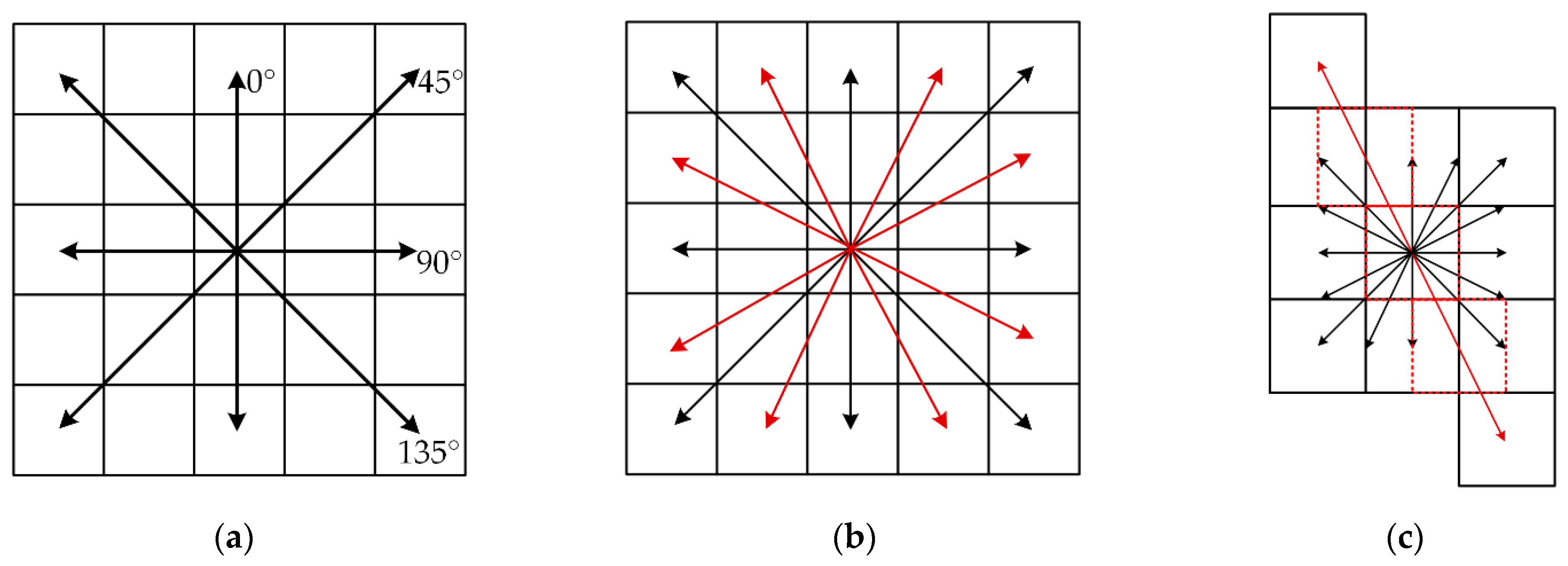
Being one of the most common methods for feature points extraction, Moravec calculates the grayscale variance of adjacent pixels along four directions and compares the minimum with a specific threshold. Figure 3 presents the template of traditional Moravec in five pixels with four directions of detection. The variance of grayscale value can be calculated as follows.
V = ( g x , y g x + m , y + n ) 2 { m = 1 ,   n = 0 ,   0 ° m = 1 ,   n = 1 ,   45 ° m = 0 ,   n = 1 ,   90 ° m = 1 ,   n = 1 ,   135 °
where V denotes the grayscale variance of each direction, g presents the grayscale value of the image pixel, and m and n are a specific value decided in different directions.
There are two limits if the Moravec is directly applied to SAR orthophoto matching. First, Moravec only computes the grayscale information in four directions, which is insufficient to accurately determine the minimum grayscale variance of the pixel. Second, due to the side-looking imaging mechanism, the process of range direction is very different from the azimuth direction [40], and the Moravec is not qualified to deal with the difference. Therefore, in order to resolve these limits and boost the matching accuracy, based on Moravec, a modified SAR-Moravec template is proposed. First, four more directions are added to improve the ability of obtaining the minimum grayscale variance and decrease the influence of speckle noise. Second, since the characteristics in azimuth and range directions are different, we rotate the traditional template to make sure the main direction is consistent with the azimuth direction. The main direction is different from the average directions in its length and the size of the template is determined by specific data in experiments.
In the modified SAR-Moravec template, the direction lines after rotation are not necessarily across the center of other pixels. To calculate the grayscale variance, the simulated pixels in a red dotted frame (Figure 3c) are getting involved. Their grayscale values are the interpolation of overlapped pixels. The rotation angle can be calculated by location vectors of the satellite in image header files like XML file, and the formula is as follows.
tan α = ( x i x ¯ ) ( y i y ¯ ) ( x i x ¯ ) 2 ( i = 1 , 2 , , n )
where ( x i , y i ) denotes the coordinate of location vectors of the satellite, ( x ¯ , y ¯ ) is the mean value of these vectors, n is the number of them, and α presents the rotation angle in the template. As the angle is defined, the interpolation process can be performed. According to the positions of the pixel center and direction line, real or simulated pixels are confirmed to participate in the calculation of grayscale variance. The formula of the interpolation process is as follows.
g = p i g i ( i = 1 , 2 , , n )
where g denotes the grayscale value of real pixels overlapped, p is the weight of them, g is the grayscale value of simulated pixels, and n presents the number of real pixels overlapped.

3.2. Template Determining

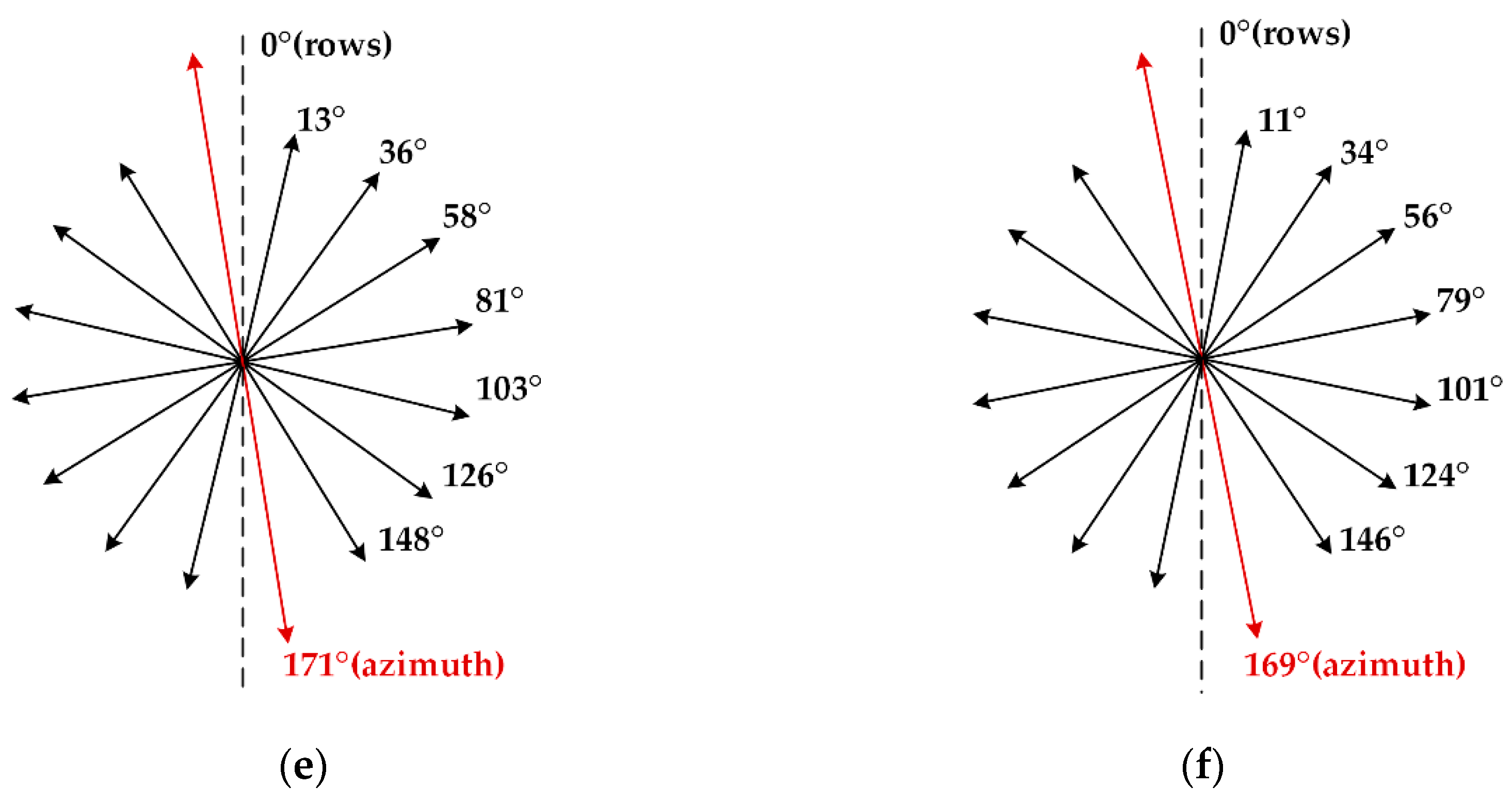
The template size is one of the most critical parameters in this method. Generally, the main direction to average direction ratio of the template is inversely proportional to the ratio between the azimuth and range resolution. In the template determination of Radarsat-2 Extra Fine orthophoto, the average incidence angle is 36.5°. After calculating by using the incidence angle, the ground range resolution is 4.650 m, the azimuth resolution is 2.9 m, and the ratio of them is 1.603. Our final choice (7 * 11) is the result of compromise between the closeness to resolution ratio and the computing cost. To verify the effectiveness of the choice, three kinds of average directions are used (5, 7, and 9 pixels) in the following experiment, according to the resolution of Radarsat-2 [41]. Twenty-four templates with a different main direction size are tested, and the results are shown in Figure 4a,b. The 7 * 11 template size shows the best global matching accuracy and relatively good performance in computing time. The template size of Sentinel-1 Interferometric Wide Swath orthophoto is determined similarly. The average incidence angle is 38.2°. Due to the process of multi-looking, the ground range resolution is 18.555 m, the azimuth resolution is 14.1 m, and the ratio of them is 1.316. Three kinds of average directions are used (3, 5, and 7 pixels), according to the resolution of Sentinel-1. Another 24 templates with a different main direction size are tested to process the slice of Data 3. The final choice is 5 * 7 and related experimental results are presented in Figure 4c,d.

3.3. Matching Procedure

Usually, when the matching process is undertaken, a specific evaluation index is set up as a measurement in feature points extraction at first [42]. Then, with the similarity measure calculated, the matching points can be obtained from these feature points. Lastly, due to the random sample consensus (RANSAC) filtering the outliers, the correct matching points are reserved to construct a stable transformation model of image pairs [43].
However, SAR orthophoto has very different properties from optic images. The specific properties should be considered during matching. Therefore, after the optimization of the template for feature points extraction, we have made the following modifications in the matching procedure. It is a matching strategy from coarse to fine, which utilized the Gaussian pyramid [44] to improve the accuracy of the transformation model per layer. At the same time, the grid control is applied in feature points extraction for evenly distributed matching points in a large area. The matching procedure in detail is illustrated in Figure 5. The whole matching procedure contains three steps. First, the Gaussian pyramid images are constructed by the down-sampling process. Second, under grid control, the feature points are extracted by the modified template. Third, the transformation model is iteratively calculated from the first to the last layer of the pyramid and the traversal areas of the next matching layer are iteratively predicted by the model. After the matching process layer-by-layer, the final matching points and transformation model can be obtained.
Based on the traditional matching process in area-based methods [42,45], in this procedure, three modifications are emphatically proposed. First, the original transformation model can be calculated by coarse matching, which is used for matching points prediction in a Gaussian pyramid. After down-sampling, the top layer of the pyramid has the lowest resolution and the simplest texture information. The global traversal is suitable to process the top layer image. Second, grid control for image matching per layer can relieve the influence of terrain types and improve the performance of matching points distribution [45,46]. Then, the global accuracy of matching in a large area can be guaranteed. Third, from a coarse type to a fine type, the maximum deviation of matching points and predicted points in the current layer is applied as the prediction range of fine matching in the next layer. This process improves the traversal efficiency with reduced and accurate location after prediction.

3.4. Evaluation Criteria of Matching

In this paper, the evaluation criteria of matching results are classified as matching efficiency, matching accuracy, the correct ratio of matching points, and the distribution of matching points. With these evaluation criteria calculated and analyzed, we can make an intuitive comparison on SAR-Moravec and other methods (Moravec, SAR-FAST, and SAR-SIFT) of their matching results. The criteria are defined as follows.
  • Matching efficiency: Time consumption of the whole procedure is used to indicate the matching efficiency of each method.
  • Matching accuracy: To quantitatively evaluate the accuracy of matching points, the standard deviation (SD) and root mean square error (RMSE) are formulated. SD can be calculated for evaluating the average pixel error. RMSE can be calculated for measuring the alignment of all matching points. These two criteria are formulated as follows.
d i = ( x m , i x p , i ) 2 + ( y m , i y p , i ) 2
S D = 1 N i = 1 N ( d i d ¯ ) 2
R M S E = 1 N i = 1 N d i 2
In Equation (4), ( x m , i ,   y m , i ) represents the location of matching point i and ( x p , i ,   y p , i ) represents the predicted location of the matching point i . The predicted location is calculated by the transformation model. d i is the matching error value of point i . In Equations (5) and (6), d ¯ denotes the average error value of all matching points.   N represents the number of matching points.
3.
Correct ratio of matching points: The extraction of feature points is the first step in area-based matching and feature-based matching. The quality of them is one important factor of the correct ratio of matching points. To utilize this criterion, we calculate the correct matching ratio (CMR) [22] as follows.
C M R = N c o r r N o r i g
where N c o r r denotes the number of correct matching points after the process of RANSAC, which we called inliers. N o r i g represents the number of all matching points before RANSAC, which includes false matching points (outliers).
4.
Distribution of matching points: Due to the existence of different terrain types in wide swath SAR orthophotos, the distribution of matching points is extremely impacted by the texture information. In the matching procedure of SAR-Moravec, we design the regular grid to optimize the distribution of matching points. The grid control in the SAR orthophoto can be utilized in a large area. The global distribution density (GDD) can evaluate the performance of distribution, which is formulated as follows.
G D D = i = 1 N [ ( G i ) G ¯ ] 2 i = 1 N G i
where G i represents the number of matching points in the regular grid i , and G ¯ denotes the mean number of matching points in all grids. N is the number of regular grids in experimental data.

4. Results and Discussion

4.1. Feature Points Extraction of Moravec and SAR-Moravec

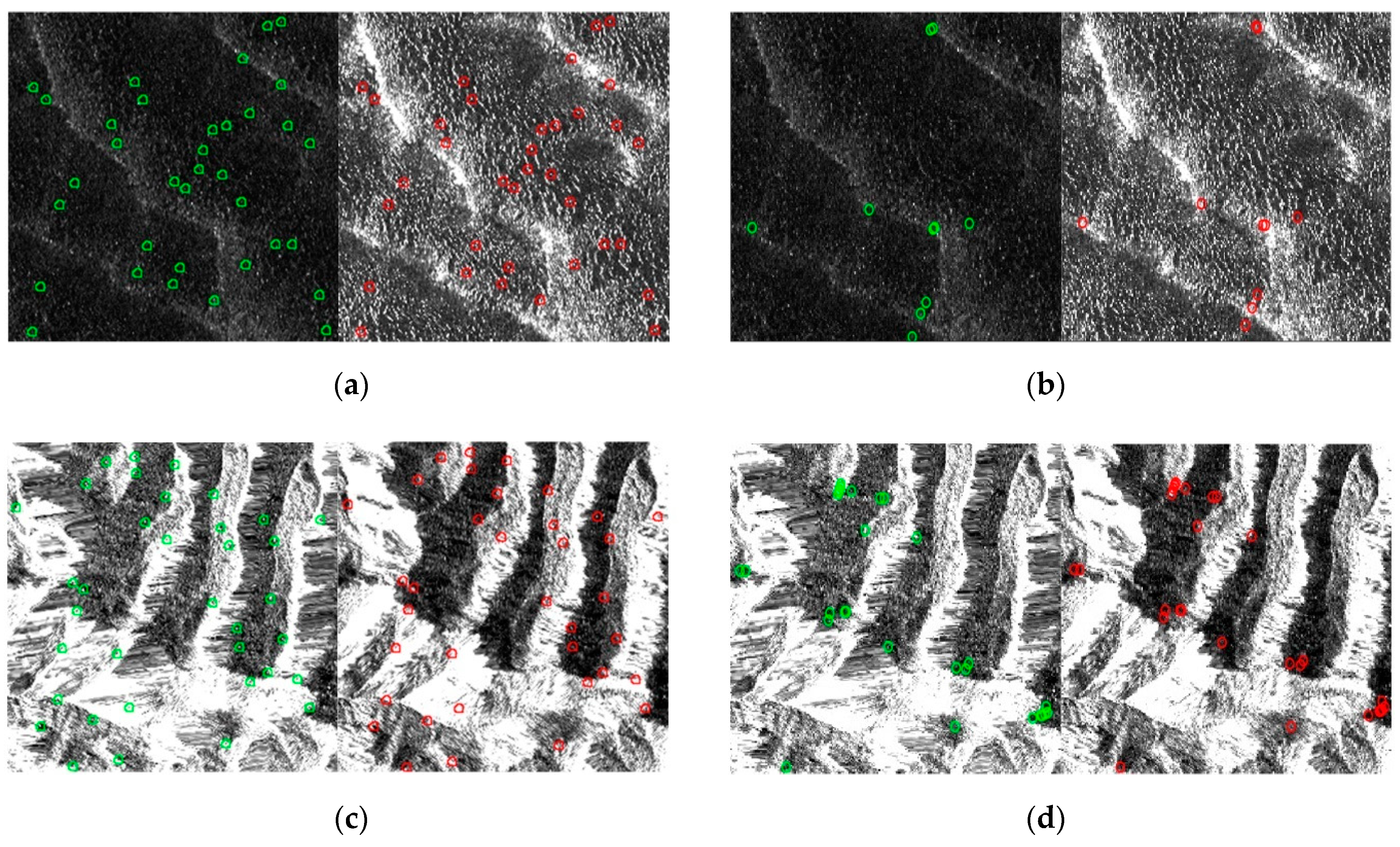
The quality of feature points can seriously influence the matching results [47,48]. Ordinarily, the qualified feature points with high grayscale variance are closer to the edge of objects. In feature-based methods, the strong feature descriptor is often located in a sharp gradient area [48]. Calculated by area-based feature points extraction of Moravec and SAR-Moravec, the grayscale variance of feature points shows a higher value than other points. To compare the quality of features points extracted by Moravec and SAR-Moravec, Data 3 are processed and the detailed extraction results are zoomed in for clear presentation. Figure 6 shows the extraction results of two slices in Data 3 by Moravec and SAR-Moravec. The detailed presentation should be analyzed to confirm the improvement of SAR-Moravec feature points extraction.
Shown in the detailed presentation of extraction results, the quality of feature points extracted by SAR-Moravec performs better than Moravec. Compared point A with point D (and compared point H with point I), the feature points extracted by SAR-Moravec are closer to the edge of objects. Compared point F with point C and point G, the feature points with small changes of grayscale information are filtered in SAR-Moravec extraction. Meanwhile, the feature points filtered by Moravec can be directly detected in SAR-Moravec. Compared point B with point E, they are the same feature points both extracted by Moravec and SAR-Moravec. Due to more detecting directions and the adaptation to the rotation angle in SAR orthophoto, the quality of feature points extracted are much better by the template of SAR-Moravec. It can be concluded that the proposed method, SAR-Moravec, apparently promotes the performance on feature points extraction in SAR orthophoto.

4.2. Experiment of Adaptability Compared with SAR-SIFT

To compare the performance of SAR-Moravec with feature-based methods in different terrain types, we process four pairs of slices in Data 1 (200 * 200) by SAR-Moravec and SAR-SIFT. Table 2 presents the matching results with the evaluation criteria above (Matches, SD, RMSE, CMR, and Time consuming). The matching results of these two methods are illustrated in Figure 7.
Seen from the results of Figure 7, the matching points extracted by SAR-Moravec distribute more evenly than SAR-SIFT. The grid control process contributes good matching results in each terrain type of the slices. According to the evaluation criteria in Table 2, SAR-Moravec can extract more matching points than SAR-SIFT regardless of terrain types. Furthermore, SAR-Moravec shows higher SD and RMSE, even in areas with weak texture information. In the residential area, the improvement is not clear enough. Both methods can reach high-accuracy results in the rich texture information area. However, the SAR-Moravec has higher CMR than SAR-SIFT, which means the SAR-Moravec has better ability to obtain matching point. In time consuming, SAR-Moravec performs significantly better than SAR-SIFT. Therefore, SAR-Moravec is more effective and efficient than feature-based SAR-SIFT in SAR orthophoto matching.

4.3. Experiment of Adaptability in Different Terrain Types

To verify the SAR-Moravec method applicable to SAR orthophoto matching in different terrain types, slices of representative terrains from Sentienl-1 are prepared for this experiment in Section 2. Twelve pairs of slices classified into four terrain types are processed in SAR-Moravec matching. Four evaluation criteria above, including Matches, SD, RMSE, and CMR, can be utilized in analyzing the matching results of different terrain types. The matching results are illustrated in Figure 8 and the detailed indicators are presented in Table 3.
Illustrated in Figure 8, the number of matching points (Matches) in desert areas and plain areas are relatively low for the weak texture information, especially in desert areas. In mountain areas, the change of elevation makes the texture information complicated, which increases the number of matching points. In resident areas, the existence of numerous artificial features with rich texture information also increases the number of matching points. Presented in Table 3 and Figure 8, the number and distribution of matching points can impact the matching criteria of SD, RMSE, and CMR. With good feature points extracted in SAR-Moravec, the matching accuracy and CMR can be promoted. Furthermore, because of the shadow and layover phenomena in mountain areas [49], the matching accuracy (SD, RMSE) and CMR are both lower than resident areas. Due to the weak texture information, less feature points are extracted in desert and plain areas. It leads to less matching points in these slices. However, the matching accuracy of different slices all reach a subpixel level. Therefore, SAR-Moravec can deal well with different terrain types and is suitable to the matching procedure of complex-terrain SAR orthophotos in a large area.

4.4. Experiment of SAR Orthophoto Matching

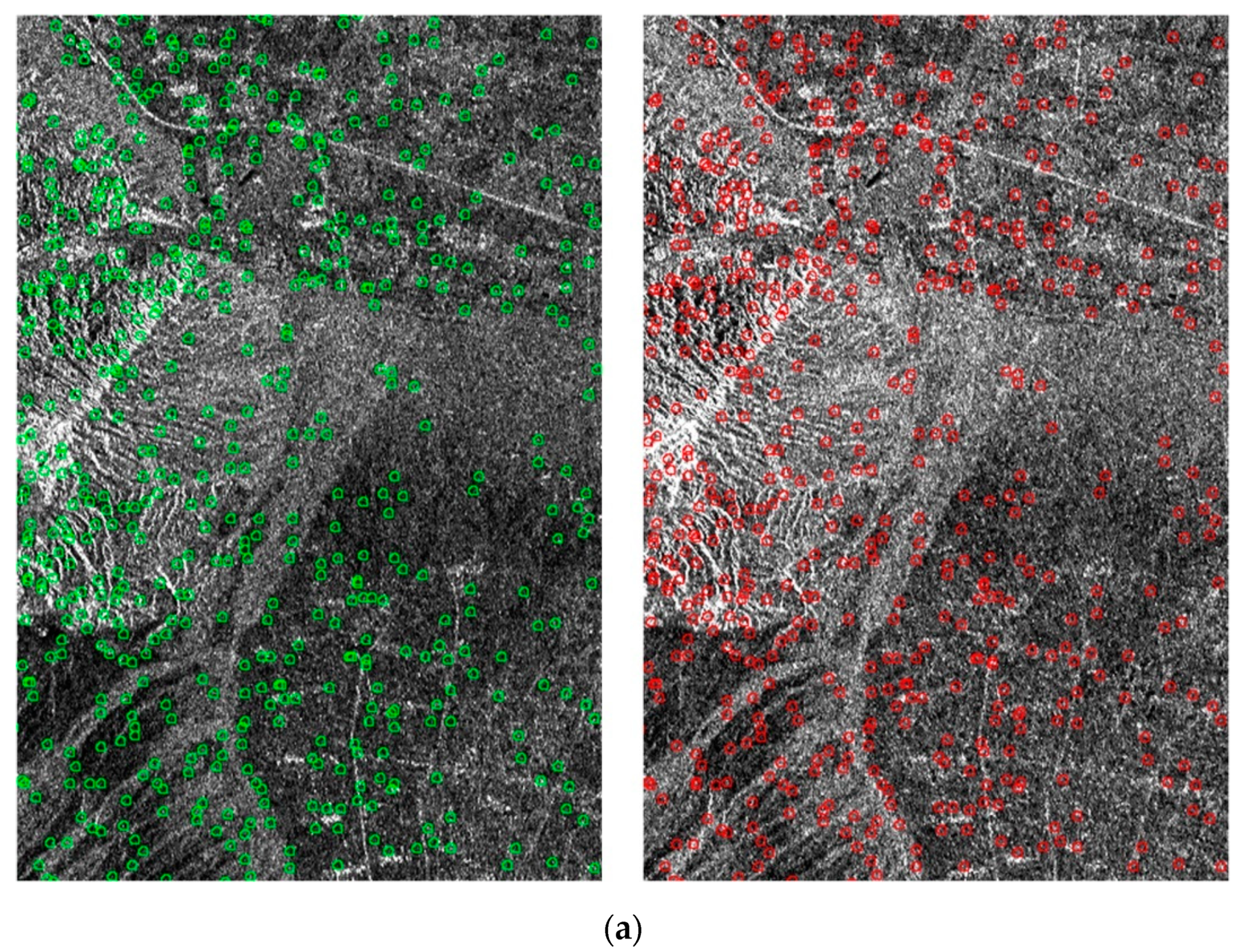
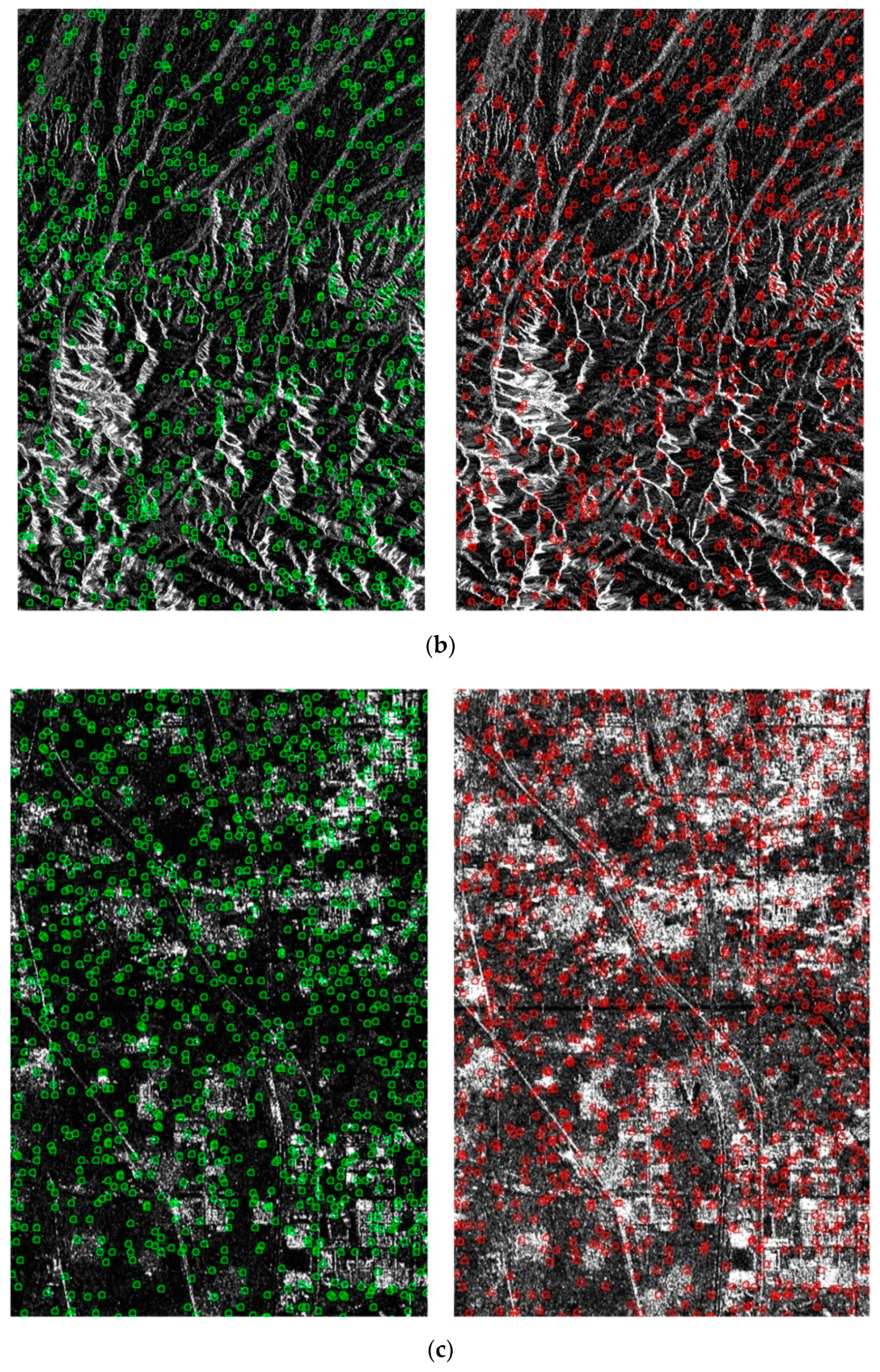
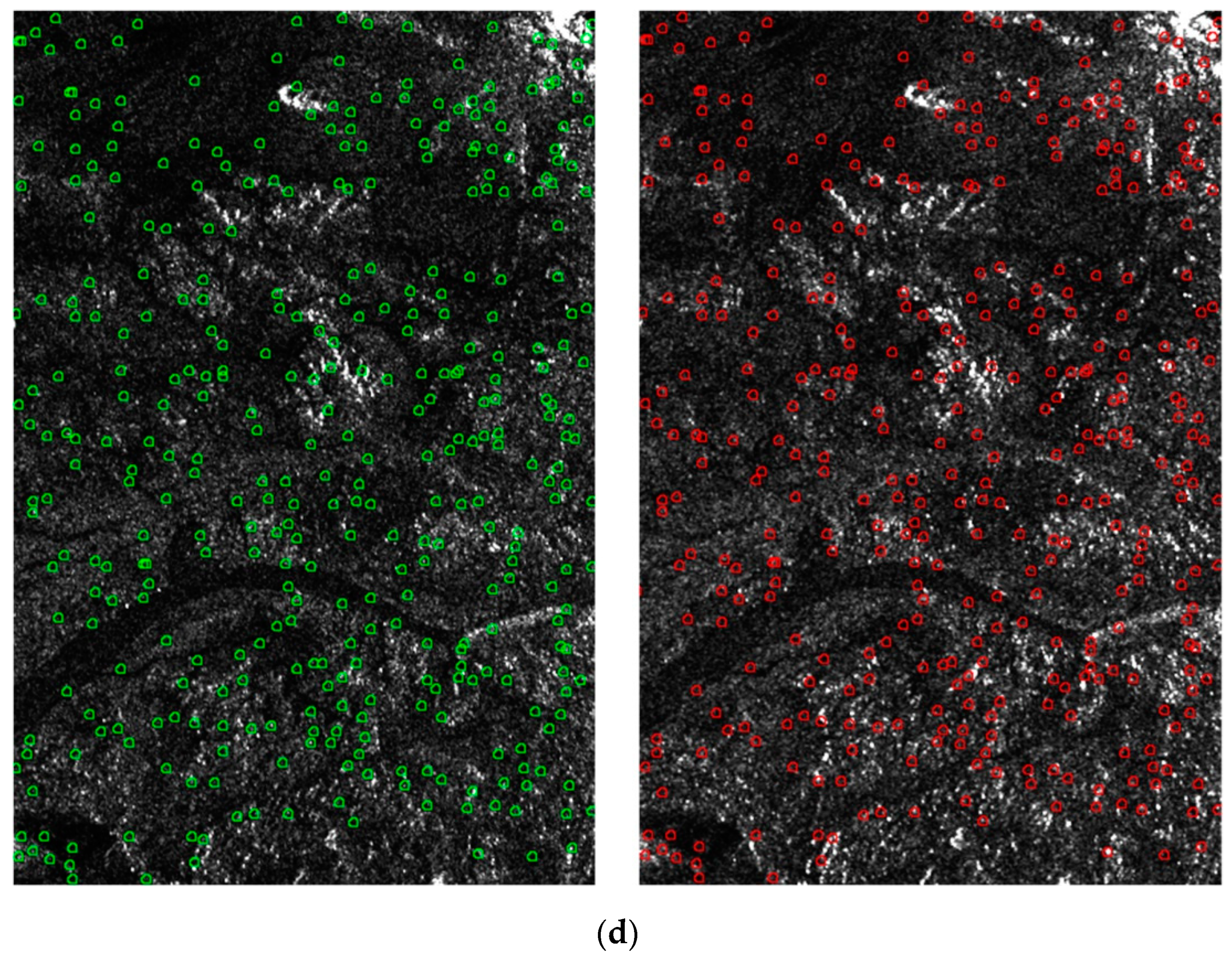
In this part, the whole swathes of SAR orthophotos from adjacent orbits are used. Figure 9 illustrates parts of the matching results by SAR-Moravec. Table 4 presents the matching results of four data by methods including Moravec, SAR-FAST, SAR-SIFT, and SAR-Moravec. With evaluation criteria of SD, RMSE, CMR, GDD, and time consuming, the different matching results can be analyzed in detail. GDD in feature-based matching methods is obtained by the same regular grids utilized in area-based methods.
Shown in Figure 9, the SAR-Moravec has a good performance on distribution of matching points in these data. Compared with the other three methods, SD and RMSE criteria both show that the global matching accuracy of SAR-Moravec is the best. SAR-FAST and SAR-SIFT show moderate matching accuracy. The SAR-SIFT, which does not contain a grid control process, shows the lowest matching accuracy. In terms of GDD, the area-based methods with a grid control process perform well in matching points distribution. Especially in SAR-Moravec matching, the quality of feature points is better than other methods and the distribution performance is clearly promoted. In terms of time consuming, though slightly slower than Moravec, area-based SAR-Moravec is still more efficient than the other two modified methods. Considering all the evaluation criteria in the experiment, it can be concluded that SAR-Moravec shows good matching accuracy and matching efficiency in SAR orthophoto matching from adjacent orbits in a large area.

5. Conclusions

This paper proposed a modified area-based Moravec method for SAR orthophoto matching from adjacent orbits in a large area. In the feature points extraction, detecting more directions are added into the template to relieve the impact of speckle noise. Meanwhile, the main direction of the template is set up to adapt the rotation angle after terrain correction in SAR orthophoto. This template can improve the quality of feature points in SAR orthophoto matching. In the matching procedure, a coarse-to-fine matching process with Gaussian pyramid and grid control is designed to improve its adaptability in a large area and the homogeneity of feature points distribution. The coarse-to-fine matching in the Gaussian pyramid can effectively decrease the time consumption in a traversal process. The even distribution of matching points can ensure the stability of the transformation model and further improve the adaptability to different terrain types.
In the experiments, Radarsat-2 and Sentienl-1 data are used to analyze the effectiveness of the proposed method in SAR orthophoto in a large area. First, according to the experiment results of the comparison with Moravec, it can be demonstrated that the modified template improves the performance on feature points extraction in SAR orthophoto. Then, according to the experiment results of the adaptability to different terrain types, the proposed method is better than SAR-SIFT and, thus, more suitable for SAR image matching in complex terrain areas. At the end, according to the experiment results of the SAR orthophoto matching, it can be concluded that, though the time consuming is slightly longer than the original Moravec, it still has better global matching accuracy and better feature points distribution than other methods (SAR-SIFT and SAR-FAST). In conclusion, it is invulnerable to terrain types and capable of generating evenly distributed and high accuracy matching points. The proposed method can be widely applied in orthophoto matching from adjacent orbits in a large area.

Author Contributions

Conceptualization, H.G, C.H., and Y.D. Methodology, C.H., Y.D. and W.L. Software, W.L. Validation, C.H., Y.D. and W.L. Formal analysis, Y.D. and W.L. Investigation, C.H. and W.L. Resources, H.G., C.H. and Y.D. Data curation, C.H. and W.L. Writing—original draft preparation, C.H. and W.L. Writing—review and editing, Y.D. Visualization, W.L. Supervision, C.H. and Y.D. Project administration, H.G., C.H. and Y.D. Funding acquisition, H.G. and C.H. All authors have read and agreed to the published version of the manuscript.

Funding

The Strategic Priority Research Program of the Chinese Academy of Sciences [XDA19030101], the National Key Research and Development Program of China [2018YFC0213600], and the National Natural Science Foundation of China [41590853] supported this work.

Conflicts of Interest

The authors declare no conflict of interest.

References

  1. Luscombe, A. Image quality and calibration of RADARSAT-2. In Proceedings of the 2009 IEEE International Geoscience and Remote Sensing Symposium, Cape Town, South Africa, 12–17 July 2009; pp. II-757–II-760. [Google Scholar]
  2. Williams, D.; LeDantec, P.; Chabot, M.; Hillman, A.; James, K.; Caves, R.; Thompson, A.; Vigneron, C.; Wu, Y. RADARSAT-2 image quality and calibration update. In Proceedings of the EUSAR 2014; 10th European Conference on Synthetic Aperture Radar, Berlin, Germany, 3–5 June 2014; pp. 1–4. [Google Scholar]
  3. Geudtner, D.; Torres, R.; Snoeij, P.; Davidson, M.; Rommen, B. Sentinel-1 system capabilities and applications. In Proceedings of the 2014 IEEE Geoscience and Remote Sensing Symposium, Quebec City, QC, Canada, 13–18 July 2014; pp. 1457–1460. [Google Scholar]
  4. Prats-Iraola, P.; Nannini, M.; Scheiber, R.; De Zan, F.; Wollstadt, S.; Minati, F.; Vecchioli, F.; Costantini, M.; Borgstrom, S.; De Martino, P. Sentinel-1 assessment of the interferometric wide-swath mode. In Proceedings of the 2015 IEEE International Geoscience and Remote Sensing Symposium (IGARSS), Milan, Italy, 26–31 July 2015; pp. 5247–5251. [Google Scholar]
  5. Han, B.; Zhong, L.; Liu, J.; Qiu, X.; Hu, Y.; Lei, B. SAR data processing for GF3. In Proceedings of the EUSAR 2018; 12th European Conference on Synthetic Aperture Radar, Aachen, Germany, 4–7 June 2018; pp. 1–6. [Google Scholar]
  6. Jiao, N.; Wang, F.; You, H.; Qiu, X.; Yang, M. Geo-Positioning Accuracy Improvement of Multi-Mode GF-3 Satellite SAR Imagery Based on Error Sources Analysis. Sensors 2018, 18, 2333. [Google Scholar] [CrossRef] [PubMed] [Green Version]
  7. Wulder, M.A.; White, J.C.; Fournier, R.A.; Luther, J.E.; Magnussen, S. Spatially explicit large area biomass estimation: Three approaches using forest inventory and remotely sensed imagery in a GIS. Sensors 2008, 8, 529–560. [Google Scholar] [CrossRef] [PubMed] [Green Version]
  8. Chang, L.; Dollevoet, R.P.; Hanssen, R.F. Nationwide railway monitoring using satellite SAR interferometry. IEEE J. Sel. Top. Appl. Earth Obs. Remote Sens. 2016, 10, 596–604. [Google Scholar] [CrossRef]
  9. Amitrano, D.; Di Martino, G.; Iodice, A.; Riccio, D.; Ruello, G.; Ciervo, F.; Papa, M.N.; Koussoubé, Y. Effectiveness of high-resolution SAR for water resource management in low-income semi-arid countries. Int. J. Remote Sens. 2014, 35, 70–88. [Google Scholar] [CrossRef]
  10. Vassilopoulou, S.; Hurni, L.; Dietrich, V.; Baltsavias, E.; Pateraki, M.; Lagios, E.; Parcharidis, I. Orthophoto generation using IKONOS imagery and high-resolution DEM: A case study on volcanic hazard monitoring of Nisyros Island (Greece). Isprsj. Photogramm. Remote Sens. 2002, 57, 24–38. [Google Scholar] [CrossRef]
  11. Sheng, Y.; Alsdorf, D.E. Automated georeferencing and orthorectification of Amazon basin-wide SAR mosaics using SRTM DEM data. IEEE Trans. Geosci. Remote Sens. 2005, 43, 1929–1940. [Google Scholar] [CrossRef]
  12. Georgopoulos, A.; Natsis, S. A simpler method for large scale digital orthophoto production. Int. Arch. Photogramm. Remote Sens. Spat. Inf. Sci. 2008, 37, 266. [Google Scholar]
  13. Wu, B.; Hu, H.; Guo, J. Integration of Chang’E-2 imagery and LRO laser altimeter data with a combined block adjustment for precision lunar topographic modeling. Earth Planet. Sci. Lett. 2014, 391, 1–15. [Google Scholar] [CrossRef]
  14. Bányai, L.; Szűcs, E.; Wesztergom, V. Data quality of sentinel-1 IW SLC images and artificial twin backscatterers designed for 3D surface change monitoring with the fusion of PSI and GNSS techologies. ESASP 2016, 740, 390. [Google Scholar]
  15. Bayanudin, A.A.; Jatmiko, R.H. Orthorectification of Sentinel-1 SAR (Synthetic Aperture Radar) Data in Some Parts Of South-eastern Sulawesi Using Sentinel-1 Toolbox. Iop Conf. Ser. Earth Environ. Ence 2016, 47, 012007. [Google Scholar] [CrossRef]
  16. Zhang, G.; Wu, Q.; Wang, T.; Zhao, R.; Deng, M.; Jiang, B.; Li, X.; Wang, H.; Zhu, Y.; Li, F. Block adjustment without GCPs for Chinese spaceborne SAR GF-3 imagery. Sensors 2018, 18, 4023. [Google Scholar] [CrossRef] [PubMed] [Green Version]
  17. Ghannadi, M.A.; Saadatseresht, M. A Modified Local Binary Pattern Descriptor for SAR Image Matching. IEEE Geosci. Remote Sens. Lett. 2018, 16, 568–572. [Google Scholar] [CrossRef]
  18. Cruz-Mota, J.; Bogdanova, I.; Paquier, B.; Bierlaire, M.; Thiran, J.-P. Scale invariant feature transform on the sphere: Theory and applications. Int. J. Comput. Vis. 2012, 98, 217–241. [Google Scholar] [CrossRef]
  19. Bay, H.; Ess, A.; Tuytelaars, T.; Gool, L.V. Speeded-Up Robust Features (SURF). Comput. Vis. Image Underst. 2008, 110, 346–359. [Google Scholar] [CrossRef]
  20. Dubois, C.; Nascetti, A.; Thiele, A.; Crespi, M.; Hinz, S. SAR-SIFT for Matching Multiple SAR Images and Radargrammetry. Pfg-J. Photogramm. Remote Sens. Geoinf. Sci. 2017, 85, 149–158. [Google Scholar] [CrossRef]
  21. Dellinger, F.; Delon, J.; Gousseau, Y.; Michel, J.; Tupin, F. SAR-SIFT: A sift-like algorithm for SAR images. IEEE Trans. Geosci. Remote Sens. 2014, 53, 453–466. [Google Scholar] [CrossRef] [Green Version]
  22. Wang, B.; Zhang, J.; Lu, L.; Huang, G.; Zhao, Z. A uniform SIFT-like algorithm for SAR image registration. IEEE Geosci. Remote Sens. Lett. 2015, 12, 1426–1430. [Google Scholar] [CrossRef]
  23. Zhu, H.; Ma, W.; Hou, B.; Jiao, L. SAR image registration based on multifeature detection and arborescence network matching. IEEE Geosci. Remote Sens. Lett. 2016, 13, 706–710. [Google Scholar] [CrossRef]
  24. Paul, S.; Pati, U.C. SAR image registration using an improved SAR-SIFT algorithm and Delaunay-Triangulation-Based local matching. IEEE J. Sel. Top. Appl. Earth Obs. Remote Sens. 2019, 12, 2958–2966. [Google Scholar] [CrossRef]
  25. Stephens, M.; Harris, C. 3D wire-frame integration from image sequences. Image Vis. Comput. 1989, 7, 24–30. [Google Scholar] [CrossRef]
  26. Qi, Z.; Ting, R.; Husheng, F.; Jinlin, Z. Particle filter object tracking based on Harris-SIFT feature matching. Procedia Eng. 2012, 29, 924–929. [Google Scholar] [CrossRef] [Green Version]
  27. Liu, M.; Wu, C.; Zhang, Y. Multi-resolution optical flow tracking algorithm based on multi-scale Harris corner points feature. In Proceedings of the Control and Decision Conference, Yantai, China, 2–4 July 2008. (In Chinese). [Google Scholar]
  28. Gundogdu, E.; Alatan, A.A. Good features to correlate for visual tracking. IEEE Trans. Image Process. 2018, 27, 2526–2540. [Google Scholar] [CrossRef] [PubMed] [Green Version]
  29. Changwei, C. A fast matching algorithm based on corner detection and SIFT algorithm. Comput. Appl. Softw. 2014, 31, 214–216. [Google Scholar]
  30. Rosten, E.; Porter, R.; Drummond, T. Faster and better: A machine learning approach to corner detection. IEEE Trans. Pattern Anal. Mach. Intell. 2008, 32, 105–119. [Google Scholar] [CrossRef] [PubMed] [Green Version]
  31. Yu, H.; Liu, Y.; Li, L.; Yang, W.; Liao, M. Stable feature point extraction for accurate multi-temporal SAR image registration. In Proceedings of the 2017 IEEE International Geoscience and Remote Sensing Symposium (IGARSS), Fort Worth, TX, USA, 23–28 July 2017; pp. 181–184. [Google Scholar]
  32. Yu, H.; Yang, W.; Liu, Y. Coarse-to-Fine Accurate Registration for Airborne SAR Images Using SAR-FAST and DSP-LATCH. Prog. Electromagn. Res. 2018, 163, 89–106. [Google Scholar] [CrossRef] [Green Version]
  33. Yan, L.; Huai, Y.; Wen, Y.; Li, L. SAR image registration using SAR-FAST corner detection. J. Electron. Inf. Technol. 2017, 2, 430–436. [Google Scholar]
  34. Al-Zaydi, Z.Q.; Ndzi, D.L.; Kamarudin, M.L.; Zakaria, A.; Shakaff, A.Y. A robust multimedia surveillance system for people counting. Multimed. Tools Appl. 2017, 76, 23777–23804. [Google Scholar] [CrossRef]
  35. Jiaoab, N.; Kangab, W.; Xiangab, Y.; Youab, H. A novel and fast corner detection method for sar imagery. In Proceedings of the International Archives of the Photogrammetry, Remote Sensing and Spatial Information Sciences, Wuhan, China, 18–22 September 2017. 42(2/W7). [Google Scholar]
  36. Xiong, W.; Tian, W.; Yang, Z.; Niu, X.; Nie, X. Improved FAST corner-detection method. J. Eng. 2019, 2019, 5493–5497. [Google Scholar] [CrossRef]
  37. Moravec, H.P. Robot: Mere machine to Transcendent Mind; Oxford University Press on Demand: New York, NY, USA, 2000. [Google Scholar]
  38. Kubica, V.; Neyt, X.; Griffiths, H.D. Validation of the increased image resolution obtained using TOPSAR sentinel-1 data in a bistatic setup. In Proceedings of the 2017 Progress in Electromagnetics Research Symposium—Fall (PIERS—FALL), Singapore, 19–22 November 2017. [Google Scholar]
  39. Giudici, D.; Mancon, S.; Guarnieri, A.M.; Piantanida, R.; Recchia, A. Enhanced processing of Sentinel-1 TOPSAR data. In Proceedings of the Igarss IEEE International Geoscience & Remote Sensing Symposium, Beijing, China, 10–15 July 2016. [Google Scholar]
  40. Li, Y.; Zhu, D. The geometric-distortion correction algorithm for circular-scanning SAR imaging. IEEE Geosci. Remote Sens. Lett. 2009, 7, 376–380. [Google Scholar]
  41. Nagler, T.; Rott, H.; Hetzenecker, M.; Wuite, J.; Potin, P. The Sentinel-1 Mission: New Opportunities for Ice Sheet Observations. Remote Sens. 2015, 7, 9371. [Google Scholar] [CrossRef] [Green Version]
  42. Gao, J.; Sun, J.Y.; Liu, J. Image matching method based on normalized grayscale variance Hausdorff distance. J. Comput. Appl. 2011, 31, 741–744. [Google Scholar] [CrossRef]
  43. Cheng, L.; Li, M.; Liu, Y.; Cai, W.; Chen, Y.; Yang, K. Remote sensing image matching by integrating affine invariant feature extraction and RANSAC. Comput. Electr. Eng. 2012, 38, 1023–1032. [Google Scholar] [CrossRef]
  44. Lin, C.; Zhou, H.-F.; Chen, W. Improved Bilateral Filtering for a Gaussian Pyramid Structure-Based Image Enhancement Algorithm. Algorithms 2019, 12, 258. [Google Scholar] [CrossRef] [Green Version]
  45. Shimizu, M.; Okutomi, M. Precise subpixel estimation on area-based matching. Syst. Comput. Jpn. 2002, 33, 1–10. [Google Scholar] [CrossRef]
  46. Molderink, A.; Bakker, V.; Bosman, M.G.; Hurink, J.L.; Smit, G.J. Management and control of domestic smart grid technology. IEEE Trans. Smart Grid 2010, 1, 109–119. [Google Scholar] [CrossRef] [Green Version]
  47. Daolian, Y.; Changhua, L.; Jinliang, Z.; Kai, Y.; Xiaoting, C. Edge detection in SAR images based on ROEWA and Hough transform. J. Electron. Meas. Instrum. 2013, 6, 543–548. [Google Scholar]
  48. Wu, B.; Zhou, S.; Ji, K. A novel method of corner detector for SAR images based on Bilateral Filter. In Proceedings of the 2016 IEEE International Geoscience and Remote Sensing Symposium (IGARSS), Beijing, China, 10–15 July 2016; pp. 2734–2737. [Google Scholar]
  49. Kropatsch, W.G.; Strobl, D. The generation of SAR layover and shadow maps from digital elevation models. IEEE Trans. Geosci. Remote Sens. 1990, 28, 98–107. [Google Scholar] [CrossRef]
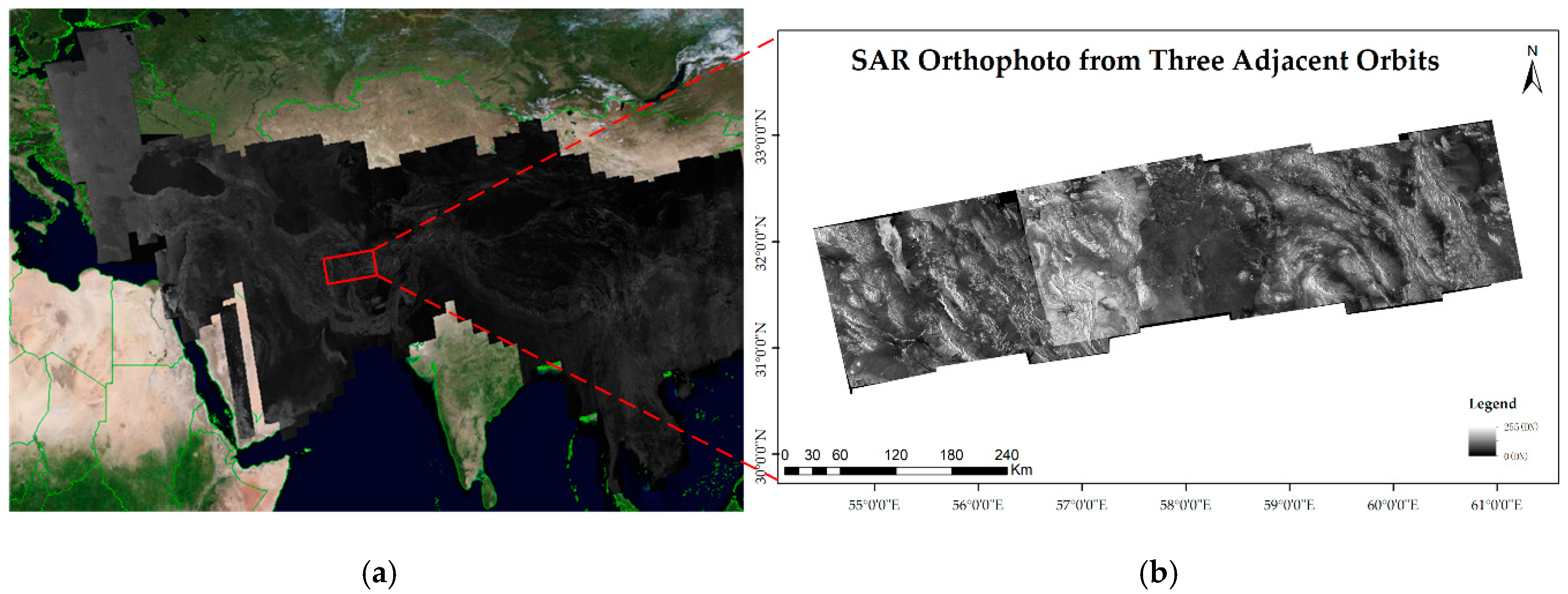
Figure 1. The presentation of areas without ground control points (GCPs) in large area. (a) The spaceborne synthetic aperture radar (SAR) orthophoto in a large area produced by Sentinel-1A Interferometric Wide Swath mode data. (b) The SAR orthophotos from three adjacent orbits in areas without GCPs, located in eastern Iran and western Pakistan.
Remotesensing 12 02892 g001
Figure 2. The characteristics of wide swath spaceborne SAR orthophotos. (a) The rotation problem of azimuth and range direction not consistent with the orientation of the image row and column in Radarsat-2. (b) The rotation problem in Sentinel-1. (c) The mountain area in wide swath SAR orthophotos without GCPs, which impact the distribution of matching points. (d) The desert area in wide swath SAR orthophotos without GCPs.
Remotesensing 12 02892 g002
Figure 3. The characteristics of templates in Moravec and SAR-Moravec. (a) Traditional Moravec template in 5 pixels. (b) The modified Moravec template with four more directions in 5 pixels. (c) Specific templates with 5 pixels along the main direction in red and 3 pixels along the average direction in black.
Remotesensing 12 02892 g003
Figure 4. Experimental results of template determining (a) shows the standard deviation of matching results in Radarsat-2 with two red vertical lines locating the best choice, (b) shows the time consuming of matching results in Radarsat-2, (c) shows the standard deviation of matching results in Sentinel-1, (d) shows the time consuming of matching results in Sentinel-1, and (e) the specific modified template of SAR-Moravec for Radarsat-2. (f) The specific modified template of SAR-Moravec for Sentinel-1.
Remotesensing 12 02892 g004aRemotesensing 12 02892 g004b
Figure 5. The procedure of SAR orthophoto matching by SAR-Moravec.
Remotesensing 12 02892 g005
Figure 6. The results of feature points extraction by Moravec and SAR-Moravec. A, B, C, G, and H are feature points extracted by Moravec. D, E, F, and I are feature points extracted by SAR-Moravec. (a) Extraction results in a part by Moravec and the details zoomed out. (b) Extraction results in the same part with (a) by SAR-Moravec. (c) Extraction results in another part by Moravec. (d) Extraction results in the same part with (c) SAR-Moravec.
Remotesensing 12 02892 g006aRemotesensing 12 02892 g006b
Figure 7. The matching results of different terrain types by SAR-Moravec (left) and SAR-SIFT (right). (a,b) Matching results in slices of desert area by SAR-Moravec and SAR-SIFT. (c,d) Matching results in slices of a mountain area by SAR-Moravec and SAR-SIFT. (e,f) Matching results in slices of the plain area by SAR-Moravec and SAR-SIFT. (g,h) Matching results in slices of the resident area by SAR-Moravec and SAR-SIFT.
Remotesensing 12 02892 g007aRemotesensing 12 02892 g007b
Figure 8. The matching results of different terrain types in a large area by SAR-Moravec. (ac) Matching results in slices of the desert area. (df) Matching results in slices of the mountain area. (gi) Matching results in slices of the plain area. (jl) Matching results in the slices of the resident area.
Remotesensing 12 02892 g008
Figure 9. The partial matching results of SAR orthophoto from adjacent orbits in a large area by SAR-Moravec. (a) The partial matching results of Data 1. (b) The partial matching results of Data 2. (c) The partial matching results of Data 3. (d) The partial matching results of Data 4.
Remotesensing 12 02892 g009aRemotesensing 12 02892 g009bRemotesensing 12 02892 g009c
Table 1. Specific information of image data.
Data NumberData SourcesLocationAcquisition Time
Data 1Radarsat-2Eastern Xinjiang in China8 April 2018 and 16 April 2018
Data 2Radarsat-2Northwestern Heilongjiang in China15 April 2018 and 23 March 2018
Data 3Sentinal-1ANorthern Ashkhabad in Turkmenistan24 March 2018 and 29 March 2018
Data 4Sentinel-1AWestern Henan in China5 May 2018 and 13 May 2018
Table 2. Experimental results of slices based on SAR-Moravec and SAR-SIFT.
SliceMethodMatchesSDRMSECMRTime Consuming
Desert AreaSAR-Moravec340.70291.510.6651.4168 s
SAR-SIFT101.33402.450.6845.7932 s
Mountain AreaSAR-Moravec470.59061.400.8891.7319 s
SAR-SIFT310.86941.880.7356.2324 s
Plain AreaSAR-Moravec330.71271.620.7601.2056 s
SAR-SIFT161.28132.530.6915.6482 s
Resident AreaSAR-Moravec880.46711.130.9111.7843 s
SAR-SIFT910.45141.120.8737.1477 s
Table 3. Experimental results of slices in four terrains based on SAR-Moravec.
SliceMatchesSDRMSECMR
Desert Area 1550.63841.480.751
Desert Area 2810.61051.590.797
Desert Area 3350.69531.650.728
Mountain Area 13170.52111.190.894
Mountain Area 22920.53041.260.863
Mountain Area 32690.52681.210.881
Plain Area 11320.54871.360.737
Plain Area 2910.61221.570.791
Plain Area 31280.58261.460.774
Resident Area 12740.44981.140.915
Resident Area 23050.46511.150.934
Resident Area 32580.41021.100.911
Table 4. Experimental results based on four methods.
Image DataMethodSDRMSECMRGDDTime Consuming
Data 1 Moravec 1 0.56241.420.8810.6684 min 16.2 s
SAR FAST 2 0.51551.280.9110.6747 min 3.8 s
SAR SIFT 3 0.53711.330.6920.28133 min 44.5 s
SAR Moravec 4 0.44671.210.9150.7054 min 35.7 s
Data 2 Moravec 1 0.61051.470.8650.7514 min 49.5 s
SAR FAST 2 0.57401.340.9080.7278 min 20.1 s
SAR SIFT 3 0.64221.390.7170.36237 min 14.6 s
SAR Moravec 4 0.46381.220.9230.7834 min 56.7 s
Data 3 Moravec 1 0.68661.490.8970.5533 min 22.0 s
SAR FAST 2 0.63281.340.9220.5765 min 13.2 s
SAR SIFT 3 0.71351.360.7510.16526 min 26.8 s
SAR Moravec 4 0.47041.240.9250.5923 min 24.9 s
Data 4 Moravec 1 0.60731.450.8720.6193 min 39.6 s
SAR FAST 2 0.53081.340.9010.5915 min 45.4 s
SAR SIFT 3 0.56291.370.7280.18829 min 57.2 s
SAR Moravec 4 0.48911.280.9040.6604 min 5.3 s
1,2,4 Moravec, SAR-FAST and SAR-Moravec are area-based matching methods that have the Gaussian pyramid in five layers. 3 SAR-SIFT is a feature-based matching method without a pyramid building process.