1. Introduction
The system-level services provided by Global Navigation Satellite System (GNSS) include Legacy PNT (positioning, navigation, and timing) and satellite-based augmentation services (SBAS). Wherein, in order to improve the accuracy of real-time service of the system, the satellite-based augmentation is to distinguish the main error sources, such as satellite orbit error, satellite clock error, and ionospheric delay, etc., and to establish models for each error source. The correction parameters can be broadcast through an independent satellite navigation augmentation system. For example, the US-American Wide Area Augmentation System (WAAS) [
1], the European Geostationary Navigation Overlay Service (EGNOS) [
2], the Japanese Multi-functional Transport Satellite Satellite-based Augmentation System (MSAS) [
3], and the Russian Satellite Differential Corrections and Monitoring (SDCM) [
4], etc. These systems are designed to operate as separate services beyond GPS or GLONASS systems.
The Chinese Beidou navigation system (BDS) adopts an integrative design for Legacy PNT and satellite-based augmentation services (SBAS), in which the SBAS provides more accurate service for authorized users. Prior to 2017, the differential information included equivalent satellite clock and ionospheric grid corrections [
5]. Among them, the equivalent satellite clock errors are used to correct the coupled error of satellite clocks and orbit radial component, while the ionospheric grid corrections to support the positioning of single-frequency (SF) users. Since 2017, the BDS SBAS has been upgraded to support decimeter level accuracy navigation and positioning for all BDS users [
6] by including real-time orbit corrections and partition comprehensive corrections [
7,
8]. BDS SBAS corrections are contained in the D2 NAV message and broadcasted by geostationary earth orbit (GEO) satellites [
9,
10].
The SBAS correction parameters have been evaluated in the carrier phase-based precise point positioning (PPP). Rho and Langley [
11] and Heßelbarth and Wanninger [
12] evaluate the SBAS carrier-phase-based PPP performance using GPS dual frequency observations. Heßelbarth and Wanninger [
12] shows that the PPP coordinate root mean square (RMS) of WAAS is of 10–30 cm and that of EGNOS and MSAS results are worse by a factor of about 3 (around 1 m). Li et al. [
13] presents an improved single frequency PPP approach based on EGNOS and shows that the SBAS PPP accuracy can reach decimeter level. El-Mowafy et al. [
14] conducted dual-frequency SBAS-based PPP for GPS and Galileo.
For the BDS SBAS system, Cao et al. first evaluate the single point positioning (SPP) performance based on the equivalent satellite clock. Results show that the positioning error can be improved by about 50% and 30% for dual-frequency and single-frequency users [
15]. With the additional orbit correction, the correlation of satellite clock and orbit error are properly separated. Compared with the equivalent satellite clock correction model, it is found that that the user rage differential range error is reduced by 27%, 32%, and 27% for GEO, Inclined Geosynchronous Orbit (IGSO), and Medium Earth Orbit (MEO) satellite, and the positioning error is also reduced from 1.17 m to 0.85 m for dual-frequency when using the combined orbit and clock correction model [
7]. For the BDS ionospheric grid correction, assessment results show that the RMS of the COMPASS grid ionospheric correction accuracy is better than 0.5 m in most regions of China [
16]. Compared with the resolution of 5° × 5° grid, the 5° × 2.5° grid that adopted in the BDS SBAS system improves the ionospheric corrections by 0.2 m and the 3D positioning accuracy also improves by 1 m in middle-low latitude regions. Wang et al. [
17] find that the contribution of BDS grid correction is comparable with the post-processed global ionosphere model (GIM) regarding SPP and PPP. For the BDS partition comprehensive corrections, although some initial precise point positioning results are given [
8], comprehensive PPP models based on these corrections are not discussed, especially for the single-frequency users.
To have a better understanding of the current BDS SBAS system, this paper focuses on the PPP performance of BDS SBAS. The four types of BDS SBAS corrections are introduced firstly. Then, we propose the dual-frequency (DF) and single-frequency (SF) PPP model using BDS SBAS corrections. The following section illustrates the properties of the four types of BDS SBAS corrections using one-month data. After that, we present the BDS SBAS corrections-based PPP performance, including accuracy and convergence. Finally, main points of this paper are discussed and concluded.
2. BDS SBAS Corrections
The current BDS broadcast four types of real-time corrections, namely the satellite orbit corrections, the satellite clock corrections, the ionosphere grid corrections, and the partial comprehensive corrections (PCC). In this section, these corrections will be briefly introduced.
2.1. Real-Time Satellite Orbit Corrections
The satellite orbit in the BDS broadcast ephemeris generally needs to be forecasted for 1~2 h, and its forecast error will increase over time. The satellite orbit correction parameters are State Space Representation (SSR)-based corrections, which makes use of the observation data of the ground observation station network of BDS to resolve the error of the satellite orbit forecast in real time [
7]. For the smoothing of the orbit corrections, zero-differenced pseudo-range and epoch-differenced carrier phase observations are combined in orbit error estimation. The orbit corrections as broadcasted by the BDS SBAS are presented in the earth-centered earth-fixed (ECEF) BeiDou coordinate system [
10] and updated every 6 min; at epoch
t0 they can be expressed as:
In the above equation, and represents the corrections and the rates of change of the satellite orbit correction in ECEF, respectively. The superscript is the satellite number, ranging from 1 to n, the total number of satellites.
From time
t0 to
ti, within the effective time of the satellite orbit corrections, the satellite orbit corrections
dx,
dy,
dz for satellite
i are calculated by:
2.2. Real-Time Satellite Clock Corrections
As mentioned earlier, the satellite clock in BDS broadcast ephemeris needs to be forecasted for 1~2 h, as its forecast error will increase over time. The first generation of BDS SBAS provides the equivalent satellite clocks, which incorporate satellite clocks and orbit radial component errors. The estimation of real-time satellite orbit errors de-correlates the orbit errors from the equivalent satellite clock corrections, thus the satellite clock corrections are resolved to correct the satellite clock errors in the broadcast ephemeris in real time [
7]. The satellite clock corrections are calculated based on the network solution using the real-time data collected from BDS monitoring stations. Using the smoothed pseudo-range observation, the satellite clock corrections are then independently provided for the B1/B2/B3 frequencies and are updated every 18 s [
5]. The UDRE after orbit and clock correction is about 0.4 m [
7].
Taking B1 for example, the clock corrections for all satellites at epoch
t0 can be expressed as:
where the superscript is the satellite number, ranging from 1 to
n, the total number of satellites. From time
t0 to
ti, within the effective time of the satellite clock corrections, the clock correction
dt for satellite
i can be derived:
2.3. Real-Time Ionospheric Grid Corrections
The BDS broadcast ephemeris provides model parameters for vertical ionosphere delay correction [
16]. It is a function that fits the measured results into 8 or 14 parameters, resulting in the loss of accuracy, and generally its update frequency is low, and the forecast time is long. The ionospheric grid corrections of BDS SBAS are used to improve the real-time ionosphere delay corrections by means of vertical delay estimation of ionospheric grid points (IGPs). The slant ionosphere delays are obtained using dual-frequency carrier smoothed pseudo-range measurements after correcting the differential code biases for satellites and receivers. By converting the slant ionosphere delay to vertical values, a spherical harmonics model is used to best-fit the ionosphere delay. Then, the gridded ionosphere delays are interpolated based on the model [
18]. The ionospheric grid covering area from 70 °E to 145 °E and 7.5 °N to 55 °N is divided into 320 grids with a resolution of 5° × 2.5°. The ionospheric grid corrections at these 320 grids are updated every 6 min [
5] and it takes users about 4 min to receive the full grid message. The RMS of BDS grid ionospheric correction accuracy is better than 0.5 m in most regions of China, and the availability is better than 95% except in the northeast and the northwest regions [
16]. Real-time ionosphere errors as broadcasted by the BDS SBAS at epoch
t0 can be expressed as:
wherein,
is the vertical ionosphere delay on the pierce grid and is divided into [1,
ln] intervals in the longitude direction and [1,
bn] intervals in the latitude direction according to the defined area. From time
t0 to
ti, within the effective time of the ionosphere corrections, the ionosphere delay function with the latitude and the longitude of the pierce point being (
b,
l) can be retrieved based on the bilinear function based on the ionosphere delays of four adjacent grid points.
2.4. Real-Time Partition Comprehensive Corrections
In addition to the above-described corrections, the BDS SBAS broadcasts the partition comprehensive correction parameters, which are used for the correction of residual errors of orbit/clock and regional environment corrections (mainly tropospheric residuals) [
7,
19,
20,
21]. The PCC parameters are basically the Observation Space Representation (OSR)-based corrections and are used to correct carrier-phase observations. The basic philosophy of BDS SBAS partition comprehensive correction is that residual observation error of the same satellite is largely similar for ground stations, which are separated by less than around 1000 km. Thus, the residual observation error of each satellite could be represented by one parameter over the whole region. Thereby, BDS SBAS designs 18 partitions over its key service area, where each partition covers an area with radius of around 800–1000 km. Real-time partition comprehensive corrections as broadcasted by the BDS SBAS are updated every 36 s and at epoch
t0 can be expressed as:
wherein each row represents a partition, ranging from 1 to
k, the total number of partitions; and different columns represent for each partition the partition comprehensive corrections of BDS satellites, ranging from 1 to
n. From time
t0 to
ti, within the effective time of the partition comprehensive corrections, the partition comprehensive correction of each satellite can be derived:
The PCC parameters are provided based on the B1/B3 ionosphere-free combinations, and they are broadcast by BDS GEO satellites and each GEO satellite broadcasts PCC parameters of 7–9 partitions. For real application, user receivers decode the PCC parameters from the observed GEO satellites, then choose the partition whose center position is the nearest to the approximate position of user receiver, and the PCC parameters of the selected partition are used to correct carrier-phase observations.
As shown by Chen et al. [
7,
19] and Zhang et al. [
20], the new BDS SBAS corrections are generated in a superimposition way: In the first step satellite, orbit/clock corrections are estimated in an iterative way; and the estimated real-time orbit/clock corrections are then used to correct the orbit/clock errors in the broadcast ephemeris during the second step where the PCC is estimated for each satellite/partition pairs.
3. Precise Point Positioning Model Based on BDS SBAS Corrections
The four types of BDS SBAS corrections are superposed on the BDS broadcast ephemeris, and the PPP [
22] could therefore be performed by using the corrections together with the broadcast ephemeris.
3.1. Dual-Frequency PPP
For users capable of dual-frequency (DF) tracking, the ionospheric-free PPP model can be expressed as:
where
and
are the pseudo-range and carrier-phase ionospheric-free combination;
is the geometric distance from station to satellite;
denotes light speed,
is the receiver clock;
is the slant tropospheric delay;
is the satellite clock after ionospheric-free combination;
is the carrier phase ambiguity after ionospheric-free combination;
is phase-windup correction after ionospheric-free combination;
and
are the remaining residuals, including multipath and the observation noise, etc. Note that in the above equation, the tidal displacements are already corrected in the station coordinate.
In traditional PPP application, the satellite orbit and clock can be derived from precise products, thus the estimated parameters would be the receiver position, receiver clock, and the residual part of tropospheric delay after model correction and the carrier phase ambiguity.
For the BDS SBAS corrections-aided PPP users, the satellite orbit and clock are derived from the broadcast ephemeris, while the errors from the satellite orbit, clock, and troposphere model can be corrected using the BDS SBAS corrections. Thus, the BDS SBAS corrections-based PPP is expressed as:
where
is the geometric distance from station to satellite computed from the broadcast ephemeris, and
is the line of sight observation correction converted from the SBAS satellite orbit correction;
is the satellite clock calculated from the broadcast ephemeris, and
is the real-time SBAS satellite clock correction (in the form of ionospheric-free combination);
is the slant tropospheric delay using the same model as in the BDS SBAS;
is the real-time SBAS partition comprehensive correction of carrier-phase, respectively. It is worth noting that the BDS broadcast clocks are referred to the B3 frequency, the timing group delay (TGD) parameters should be applied [
23] in the dual-frequency ionospheric-free combination. Meanwhile, as the partition comprehensive correction contains most parts of tropospheric residuals within a certain area, it is recommended that there is no necessity to estimate the residual tropospheric delay considering the accuracy requirement of decimeter level [
19,
20].
3.2. Single-Frequency PPP
For a single-frequency user, the SBAS ionospheric grid corrections are used to correct the pseudo-range observations, and the UofC model [
24] could be used to eliminate ionosphere delay. Taking B1 observations for example, the single frequency PPP using SBAS corrections is:
In the above equation, and are pseudo-range and carrier-phase of B1 frequency; is ionosphere correction with azimuth angle of z calculated based on the SBAS ionospheric grid corrections; is real-time SBAS satellite clock correction at the specific frequency; and are the carrier phase ambiguity and the phase-windup correction at B1 frequency, respectively; other symbols have the same meaning as in Equation (9).
On the other hand, the undifferenced and uncombined model [
25,
26] could also applied for the single-frequency PPP using the SBAS corrections, where the ionosphere is estimated as an unknown parameter and the SBAS ionospheric grid corrections can be used as weighted priori values and constraints [
17].
Similar to the dual-frequency models, the timing group delay (TGD) parameters should be applied in the above equations, so as to be consistent with the broadcast B3 frequency reference.
4. Experimental Data
The four types of BDS SBAS corrections are currently broadcasted together with ephemeris by GEO satellites, which cover the service area of Asia-Pacific region. Among the four types of corrections, orbit/clock and ionospheric grid corrections are synchronously broadcasted by the five GEOs. The partition comprehensive corrections are encoded according to the footprint of the GEO satellites, where C01 and C02 broadcast all satellites’ corrections for partitions 1–9; C03 and C04 broadcast all satellites’ corrections for partitions 7–14; and C05 broadcast all satellites’ corrections for partitions 12–18.
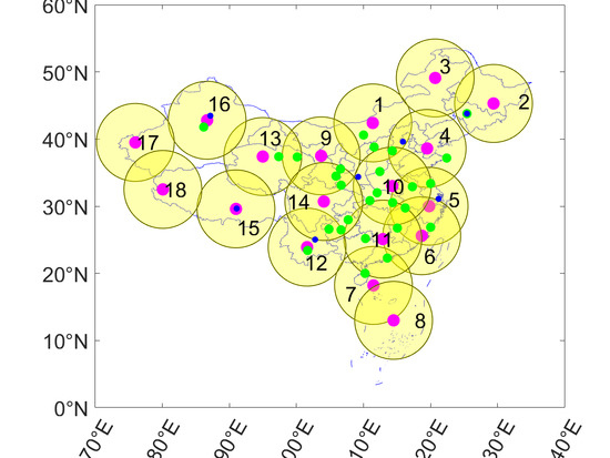
In this experiment, one-month (DoY from 32 to 59) observations in February 2019 of 34 sites were processed, including 7 iGMAS (International GNSS Monitoring and Assessment System) and 27 CMONOC (Crustal Motion Observation Network of China) sites. These sites were equipped with different antennas/receivers and are all capable of tracking BDS satellites.
Figure 1 shows the distribution of the 34 sites, where the designed partition center and coverage of each partition are illustrated as well. In this experiment, the M300TM receivers manufactured by ComNav
® were implemented to receive the BDS SBAS corrections.
In the following, we present the one-month time series of the four types of BDS SBAS corrections. For each type of satellites, one satellite was selected for representation, where C01, C06, and C11 represents GEO, IGSO, and MEO satellite, respectively. For the ionospheric grid corrections, we selected the IGP number 16 for illustration. Partition No. 6 was selected for partition comprehensive corrections representation.
4.1. Real-Time Satellite Orbit Corrections
Figure 2 shows the real-time orbit corrections for C01, C06, and C11 over one-month results, and
Table 1 gives the statistical results in three directions under ECEF. It was observed that most corrections were within the range of ±2 m, with a standard deviation (STD) of less than 0.6 m. Meanwhile, apparent periodical terms were observed for all the three components for IGSO and MEO satellites. There existed discontinuity in the time series of IGSO and MEO, which may due to the limited tracking capability of BDS ground tracking network. The visible period was around 62.67% and 22.18% for C06 and C11 and this was the typical visibility for all IGSO and MEO satellites of the BDS Ground Control Segment (GCS). For both IGSO and MEO satellites, the orbit corrections were relative larger during the entering and setting phases, and this may owe to the prediction errors of the long-time non-visible the poor observation geometry. For the GEO satellites, the Z component orbit corrections were close to zero. As the Z axis of GEO satellite was very close to the orbit radial direction, we converted the corrections from X/Y/Z in ECEF to radial/along/cross direction in satellite-fixed coordinate system and found that the radial corrections were all zero, which implies that zero-constrain has been applied to the GEO orbit correction estimation in the BDS GCS.
4.2. Real-Time Satellite Clock Corrections
Figure 3 shows the real-time clock corrections for the three satellites on different frequencies. It is worth noting that as the satellite clock corrections at B1 and B3 frequencies were exactly the same, thus it is not presented in the figure. The corresponding statistical results are listed in
Table 2. Similar to the orbit corrections, the clock corrections were continuous for GEO satellites and periodically interrupted for IGSO and MEO satellites. The longest period of satellite clocks prediction reached 5.87 and 16.86 h for IGSO and MEO satellites, which shows the typical performance of the onboard atomic clocks. Compared with IGSO and MEO satellites, the maximum real-time corrections for GEO satellite were smaller and more stable, which is due to the continuous tracking of GEO satellites on the BDS monitoring stations. Small but visible differences existed between B1 and B2 frequencies, which reflects the observation noise and the un-modeled errors of the broadcast TGD parameters, where the TGDs were used to correct the difference of B1 and B2 respect to B3. Clock corrections of GEO satellites were quite stable and benefited the performance of predictions.
4.3. Real-Time Ionospheric Grid Corrections
Figure 4 shows the real-time ionospheric grid corrections for IGP 16. In the figure, hourly mean and daily mean ionospheric delays are also plotted. Daily mean showed approximate linear increase, and this may imply the increasing of ionosphere activity during this period. Besides the approximate linear trend, the time series show apparent daily similarity, where the ionospheric delays in daytime were much larger than that in nighttime. The difference between minimum and maximum values reached 2.2 m, with the overall STD of 0.44 m; detailed evaluation of the ionospheric grid corrections was presented in reference [
16]. Inaccurate corrections would lead to tens of meters positioning errors, while the positioning errors would be greatly reduced with the introduction of the real-time ionospheric grid corrections.
4.4. Real-Time Partition Comprehensive Corrections
Partition comprehensive correction is the most unique SBAS corrections as broadcasted by BDS [
8,
20]. As an example,
Figure 5 shows the real-time partition comprehensive corrections of C01, C06, and C11, in partition No. 6;
Table 3 presents the statistical results. Similar to the other BDS SBAS corrections, the PCC was continuous for GEO satellites and showed breaks for IGSO and MEO satellites. The variation range of PCC for IGSO and MEO satellites was relatively smaller than the satellite clock corrections, due to the fact that a large amount of errors were corrected using the orbit/clock corrections. Because the observation geometry changed slightly for GEO satellites, the residual regional environment corrections were also stable, which resulted in small PCC variation and less outliers for GEO satellites.
5. Performance of PPP Based on BDS SBAS Corrections
To validate the precision of BDS SBAS correction, PPP experiments were carried out in this section. For a comprehensive evaluation, positioning performance including precision and convergence time will be assessed.
5.1. Processing Strategies
All types of BDS SBAS corrections were used as corrections for the PPP models of Equations (9)–(11). In the following, we evaluate their performance in PPP. Based on the algorithm introduced in
Section 3, we developed a software named Net_Diff (
https://github.com/YizeZhang/Net_Diff). Detailed models and strategies related to data processing for BDS static/kinematic PPP are shown in
Table 4. The initial satellite orbits and clocks were calculated from the broadcast ephemeris, and they were corrected using the received BDS SBAS corrections by Equations (2) and (4) at each epoch. The tropospheric delay was corrected using the SHAtropE model [
27] and GMF mapping function [
28], which were identical to the processing model of BDS GCS. It should be noted that the rest of the wet tropospheric delay was not necessary to be estimated as a random walk parameter since the PCC contains tropospheric model error and this part of the error would be modelled very well in areas near the partition center [
20]. The BDS IGSO and MEO phase observation precision was set to 0.005 m and the priori precision of code observation was set to 0.5 m, while for GEO satellites, they needed to be down-weighted due to the worse accuracy of GEO orbits and clocks [
29,
30]. For each site, static and kinematic PPP using a Kalman filter was performed under five schemes using different observations, including: (1) The dual-frequency observation of the B1B2 and B1B3 ionospheric-free combinations, and (2) the B1/B2/B3 single-frequency observations. Following the algorithm in
Section 3, PPP was performed for each site and the estimated coordinates were compared with the precise known coordinates. For each site, we divided the daily observations into four sessions with each session containing observations of 6 h, and there were 3808 (34 stations × 28 days × 4 sessions) solutions of each schemes and 30,464 solutions in total. It should be noted that for kinematic PPP, the datasets were collected in the post mode, while data analysis was simulated in the real-time mode.
5.2. Positioning Performance
Figure 6 presents the static and kinematic positioning errors based on B1B2 DF, B1, and B2 SF solutions at SNMX station on 6 February 2019. This site was about 411 km away from the center of partition No. 9. It is obvious that a single-frequency user needed a longer convergence time than dual-frequency solution in static and kinematic PPP. The three-dimensional (3D) positioning error of DF-PPP can converge to 1.0 m in 15min and to 0.5 m in 20 min. For SF-PPP, the convergence time of ionosphere-constrained approach was better than UofC solution in all components, especially in horizontal. The main reason is that the combined observables in UofC model are dominated by the code noise [
32] and the BDS ionospheric grid corrections improve the modeling of ionosphere delays. The 3D positioning error of SF-PPP for SNMX can converge to 1.0 m in no more than one hour.
As the BDS SBAS practically supports decimeter accuracy positioning for dual-frequency users, we defined the PPP position convergence time as the epoch where 3D positioning error was less than 1 m for at least 10 min.
Figure 7 shows the magnitude distribution histogram of kinematic DF- and SF-PPP positioning errors in the horizontal and vertical components after the solution convergence. Results of all the sites during the whole month are present in
Figure 7.
It can be seen that most of the horizontal errors were distributed in the range of less than 0.3 m and 0.5 m for ionospheric-free combinations and single-frequencies. For the distribution of vertical errors, there was an approximate linear regression in proportion to vertical errors. Around 79.8% of DF-PPP solutions had a precision better than 0.3 m in horizontal and 88.1% had better than 0.5 m in vertical for B1B2 ionospheric-free combinations, while 74.7% had better than 0.3 m in horizontal and 86.9% had better than 0.5 m in vertical for B1B3 ionospheric-free combinations. For single-frequency, the positioning error distribution of the UofC and ionosphere-constrained PPP was very similar. More than 76% of the horizontal positioning errors was less than 0.5 m and over 89% less than 0.7 m in vertical for all single-frequency (B1/B2/B3) solutions.
Table 5 summarizes the RMS of the horizontal and vertical positioning errors of different PPP schemes on all days of all the test stations, where the statistical results of kinematic solutions are calculated based on the coordinates from the first converged epoch to the last epoch of an arc (6 h) and static statistics are based on the coordinates of the last epoch in each solution. For the dual-frequency user, mean static positioning precision was of (0.12 m, 0.18 m) for horizontal and vertical components, while it was of (0.16 m, 0.20 m) for kinematic PPP. As for the single-frequency user, the positioning accuracy of the UofC model was similar to the ionosphere-constrained approach, with a mean static positioning precision of (0.14 m, 0.22 m) for horizontal and vertical components, and (0.32 m, 0.40 m) for kinematic PPP. The SF-PPP performance was worse than that of dual-frequency due to the code noise and BDS ionosphere grid model errors.
5.3. Convergence Performance
To evaluate the convergence performance of BDS SBAS corrections-based DF- and SF-PPP, we calculated the mean horizontal and vertical positioning error of the first one hour every 5 min for each of the 20,720 kinematic coordinate solutions.
Figure 8 gives the convergence performance of kinematic PPP for dual- and single-frequency solutions. For the dual ionospheric-free combination solutions, the B1B2 converged faster than B1B3, where the horizontal positioning error could converge to 0.5 m in 8/15 min for the B1B2/B1B3 ionospheric-free combinations, and it took 15/18 min for the vertical component to converge to 0.5 m for these two ionospheric-free combinations. As for SF-PPP, the convergence time of the ionosphere-constrained PPP was reduced compared with the UofC model, especially in the horizontal component, which is mainly due to the introduction of the a priori BDS SBAS ionospheric grid corrections, and undifferenced models avoid noise amplification by linear combinations. Overall, the BDS SBAS corrections-based SF-PPP could converge to 0.8 m in horizontal and 1.0 m in vertical within 30 min.
6. Discussions
Owing to the unique design with GEO satellites included in the constellation, BDS enables user with the capability of better real-time positioning and navigation accuracy by means of the integration of navigation and augmentation parameters. This paper introduces the correction information of current BDS SBAS system, and assesses the positioning performance by using these corrections.
According to [
7] and [
15], it is noteworthy that currently the orbit and clock corrections are calculated by pseudo-range, which limits the accuracy of orbit correction in the along-track, cross-track directions. Although most of the residual part of these errors will be absorbed by PCC, the direction-based diversity will affect the precision of PCC and thus decrease the positioning accuracy when the users are away from the center of the partition. Therefore, more precise orbit corrections are required to improve the precision of PPP. Meanwhile, as introduced in [
8], the PCC contains residual part of phase ambiguity from the monitoring stations, which limits its application in pseudo-range. Once the phase ambiguity can be separated from PCC, pseudo-range-based users will also benefit the PCC correction. For PPP, it is expected that the convergence performance will also improve.
Currently, the BDS broadcasts the SBAS corrections only for BDS-2 satellites and all the data analysis in this paper are based on the BDS-2 satellites. With the continuous development of the BDS system, we believe that the BDS SBAS corrections-based PPP will be further improved due to increased satellite number and improved satellite geometry.
7. Conclusions
In this study, we summarize the features of the four BDS SBAS corrections, including satellite orbit/clock corrections, ionospheric grid corrections, and partition comprehensive corrections. The usage of these four types of correction in the DF- and SF-PPP models are proposed. One month of data in February 2019 from 34 stations of the iGMAS and CMONOC network is processed with different positioning schemes and their performance is evaluated. The BDS SBAS corrections-based PPP positioning accuracy is evaluated in both static and kinematic modes by comparing with known coordinates. Comprehensive statistical analyses indicated that the mean positioning accuracy of static DF-PPP can reach 12 cm and 18 cm for horizontal and vertical components. Whereas for kinematic DF-PPP, its positioning accuracy is of 16 cm in horizontal and 20 cm in vertical. Two main SF-PPP methods are evaluated, including the UofC and ionosphere-constrained models. We have shown that they have basically similar positioning performance, where the static positioning precision is (14 cm, 22 cm) for horizontal and vertical components, while it is (32 cm, 40 cm) for kinematic modes.
By using these four types of corrections, the convergence performance has been analyzed. For the DF-PPP, it takes 8 and 15 min for the B1B2 and B1B3 ionospheric-free kinematic solutions to converge to a horizontal precision of better than 0.5 m, and the convergence time is of 15 and 18 min for their vertical precision to be better than 0.5 m. For the SF-PPP, the UofC model has a longer convergence time than the ionosphere-constrained approach, which is caused by the higher noise. In general, the kinematic SF-PPP can converge to 0.8 m in horizontal and 1.0 m in vertical with 30 min.


