Article

Pre-Event Deformation and Failure Mechanism Analysis of the Pusa Landslide, China with Multi-Sensor SAR Imagery

1
School of Geological Engineering and Geomatics, Chang’an University, Xi’an 710054, China
2
Institute of Geomechanics, Chinese Academy of Geological Sciences, Beijing 100081, China
3
Faculty of Geomatics, East China University of Technology, Nanchang 330013, China
4
State Key Laboratory of Ocean Engineering, Shanghai Jiao Tong University, Shanghai 200240, China
*
Author to whom correspondence should be addressed.
Remote Sens. 2020, 12(5), 856; https://doi.org/10.3390/rs12050856
Submission received: 11 February 2020 / Revised: 27 February 2020 / Accepted: 4 March 2020 / Published: 6 March 2020

Abstract

:
The Pusa landslide, in Guizhou, China, occurred on 28 August 2017, caused 26 deaths with 9 missing. However, few studies about the pre-event surface deformation are provided because of the complex landslide formation and failure mechanism. To retrieve the precursory signal of this landslide, we recovered pre-event deformation with multi-sensor synthetic aperture radar (SAR) imagery. First, we delineated the boundary and source area of the Pusa landslide based on the coherence and SAR intensity maps. Second, we detected the line-of-sight (LOS) deformation rate and time series before the Pusa landslide with ALOS/PALSAR-2 and Sentinel-1A/B SAR imagery data, where we found that the onset of the deformation is four months before landslide event. Finally, we conceptualized the failure mechanism of the Pusa landslide as the joint effects of rainfall and mining activity. This research provides new insights into the failure mechanism and early warning of rock avalanches.

Graphical Abstract

1. Introduction

On 28 August 2017, the long-runout collapse initiated by the ridge-top rockslide in Pusa Village, Zhangjiawan Town, Guizhou Province, China, buried residential areas and caused 26 deaths with 9 missing [1]. This catastrophic disaster is a typical rock avalanche caused by combined effects of natural and anthropogenic factors in the Yunnan–Guizhou Plateau and its surrounding areas, China, which is the largest karst mountain area in China, and even in the world, occupying around 6.2 × 10⁵ km2 [2]. Due to the vulnerable geological environment and frequent anthropogenic activities in this area, more than 2800 people have been killed by landslide disasters in recent decades. The landslide showed complex geological structures and uncertain triggering factors, which makes it difficult to invert the failure mechanism. The surface deformation before the landslide and its correlation with external factors can hopefully reveal the failure mechanism and triggering factors.
Synthetic aperture radar (SAR) intensity and coherence maps have been widely used to study the landslide disasters owing to the area being free from clouds. Zhao et al. [3] detected the landslide affected area with SAR intensity maps. Mondini et al. [4] detected worldwide rapid landslides by Sentinel-1 SAR intensity maps. Raspini et al. [5] revealed the pre-event movement of the slope in Montescaglioso village of South Italy by SAR intensity information. Yun et al. [6] acquired damage proxy maps through changes in coherence maps, which were generated by pre- and post-event SAR images. Dai et al. [7] combined interferograms and their corresponding coherence maps to identify the source region and boundary of the landslide.
In addition, interferometric SAR (InSAR) can monitor the surface deformation with centimeter to millimeter precision [8,9]. It has been extensively used to monitor high-risk slopes and restore their deformation history [10,11,12,13]. Further, landslide types and failure modes can be deduced based on the pre-event deformation, which will provide great guidelines for landslide prevention and hazard mitigation [10,14,15,16]. To this end, Kang et al. [10] recovered the failure mode of the Guanling landslide in China and found that the shear failure in the locking segment of a key body triggered by heavy precipitation based on the pre-event deformation features was the cause. Dong et al. [14] and Intrieri et al. [17] captured a sudden acceleration of deformation dozens of days before the landslide of Xinmo landslide in Maoxian County, Sichuan Province through InSAR technique, which was triggered by torrential rainfall. Besides, Zhao et al. [3] addressed the mining-induced Jiweishan landslide failure mechanism through L-band ALOS/PALSAR-1 datasets. As for the loess landslides’ failure modes, Shi et al. [18] and Zhao et al. [19] revealed the irrigation triggering factor by using fusing InSAR and groundwater measurements. In addition, four loess landslides types were summarized by Liu et al. [16] based on two-dimensional surface deformation generated from ascending and descending TerraSAR datasets. Tantianuparp et al. [20] uncovered landslide failure caused by the temporal variation of water level in the Three Gorges, China, using multi-sensor SAR imagery. Bru et al. [21] applied InSAR techniques to the operational geotechnical monitoring of the Leintz Gatzaga landslide in Basque Country, Spain. Hu et al. [22] detected the deformation of seasonal landslides in Washington by time-series SAR imagery. Xu et al. [23] revealed the movement of a rainfall-driven landslide in southwestern Oregon based on soil moisture and InSAR time series.
However, as for the triggering factors and failure mechanism of rock avalanches of southwestern China, it was only analyzed based on the geotechnical engineering technique [24]. How can the landslides be identified and delineated based on the SAR images? Is there any precursory signal that can be captured? And what is the failure mechanism of the rock avalanches? To answer these questions, we took the Pusa landslide as an example, where intensity, coherence, and phase-based information were all involved. And multi-sensor SAR imagery was employed. In addition, both ascending and descending SAR data and in-situ data were collaborated to analyze the triggering factors and the failure mechanism of the Pusa landslide.

2. Study Area

Figure 1 shows the location of Pusa landslide and the coverage of SAR images. The average temperature in a year is approximate 13.6   ° C ranging from 4   ° C to 32   ° C . And the annual rainfall is abundant from May to September, which accounts for 74% of the yearly cumulative rainfall ranging from 1200 mm to 1300 mm.
The bird’s eye view of the Pusa landslide is shown in Figure 2a, where A, B, and C indicate the source area, track-abrasion area, and deposition area, respectively [25]. The depth of the sliding surface is 85 m. The on-site photos of this landslide are shown in Figure 2b–d, where the surface of the back scarp area is fragmented, and the tension crack is visible at the back edge of the remaining blocks. The scarp after the landslide is about 2100 m a.s.l.. The elevation of the deposition area is 1833 m to 1930 m. The volumes of rock material in the source area and deposition area are about 5.0 × 10⁵ m3 and 8.23 × 10⁵ m3, respectively [1].
The geological settings of the Pusa landslide is shown in Figure 3, among which the exposed lithologic formations from the top to the bottom are the Yelang Formation of the Lower Triassic (T1y), about 100 m thick, the Changxing–Dalong Formation of the Upper Permian (P2c+d) and the Longtan Formation of the Upper Permian (P2l). The thickness of P2c+d is about 50 m. The T1y consists of limestone, silty mudstone, and argillaceous siltstone. The P2c+d consists of silty mudstone, limestone, argillaceous siltstone, and coal seams. The P2l consists of argillaceous siltstone, carbonaceous mudstone, and coal seams [1]. Besides, there are six coal seams under the foot of the landslide, where the mining behaviors were mainly conducted in CS16 coal seams, resulting in several goafs underground. The formation of these goafs changed the stress state of the slope, which had the potential to cause the deformation of the slope.

3. Data and Methods

3.1. Data

Two SM3 ALOS/PALSAR-2 images acquired on 4 September 2016 and 22 January 2017, and three SM1 ALOS/PALSAR-2 images from 14 May 2017 to 6 August 2017 were used to detect pre-event deformation area of the Pusa landslide (Figure 4a). Two post-event SM1 ALOS/PALSAR-2 images acquired on 12 November 2017 and 24 December 2017 were used to identify the boundary and source area of the landslide. Twenty ascending and eighteen descending Sentinel-1A/B images were used to calculate the surface deformation of the Pusa landslide before it occurred (Figure 4b). The parameters of SAR images are listed in Table 1. The shuttle radar topography mission (SRTM) digital elevation model (DEM) with a resolution of 30 m was employed to remove the topographic phase in InSAR processing.

3.2. Methods

The flow chart for Pusa landslide analysis with multi-sensor SAR imagery is shown in Figure 5, which includes three main functions. Coherence map and intensity maps were applied to identify the landslide boundary, source area, and buried villages, while deformation maps from both L-band ALOS/PALSAR-2 and Sentinel-1 were used to retrieve pre-event deformation.

3.2.1. Coherence Estimation

Coherence can be used as a measure for the accuracy of the interferometric phase [26]. The coherence magnitude γ is the most common measure of coherence with the range of [0, 1]. Under good SAR imaging conditions, it is close to 1 for bare surfaces, but close to 0 in dense or thick vegetation, such as forests or crops. Based on these characteristics, we investigated the region where there was a vegetation-covered area before the landslide occurred but was covered by deposition after the landslide. Accordingly, we could delineate the boundary of the landslide. γ can be calculated commonly using Equation (1) based on SAR image amplitude [26,27]:
γ = | n = 1 N μ 1 n μ 2 n * | i = 1 N | μ 1 n μ 1 n * | i = 1 N | μ 2 n μ 2 n * |
where N is the number of pixels in a window, μ 1 n and μ 2 n are the complex value of master and slave images at pixel n , respectively, * denotes complex multiplication, | · | denotes the absolute value of the complex.

3.2.2. Surface Change Detection with Intensity Maps

The SAR intensity is affected by factors such as dielectric, surface roughness, and terrain slope [28]. The ratio of SAR intensity maps reflects the surface change during the period of the repeat-pass SAR images [3,29,30]. Therefore, we delineated the extent of the source area of the landslide by using two intensity maps acquired before and after the event.
To detect the small scale landslide, we adopted single-look intensity maps with a spatial resolution of 3 m. However, to decrease the serious speckle noises in the intensity maps, we filtered the intensity maps with the modified Lee filter algorithm based on statistically homogeneous pixels (SHPs). First, we selected SHPs by the modified pixel clustering algorithm based on the hypothesis test and confidence interval method (HTCI) [31]. Then the filtering weight is calculated by the local variance, mean, and coefficient of variation within the detected SHPs, which was based on a span image. The span image was defined as the sum of all intensity maps. Finally, the images were filtered by using the modified Lee filter [32] as Equation (2).
I ^ = I ¯ + b ( I I ¯ )
where I = [ I 1 , I 2 , , I N ] is a vector of intensity maps, I ¯ = [ I ¯ 1 , I ¯ 2 , , I ¯ N ] is the mean value of intensity maps, which is calculated by averaging the intensity of the detected SHPs, N is the number of SAR intensity maps, b represents the filtering weight, I ^ is the intensity vector after filtering. After removing the effects of speckle noises, the ratio k between two intensity maps can be calculated by using Equation (3) [29].
k = i = 1 n | σ 1 i 0 | i = 1 n | σ 2 i 0 |
where | σ 1 i 0 | and | σ 2 i 0 | are backscatter coefficient values for pixel i in two intensity maps, and n represents the window size.

3.2.3. Stacking Interferograms

The average deformation rate map is often used to identify the potential landslide with subtle deformation. The stacking interferograms method can be used to acquire the average deformation rate with high accuracy. As the atmospheric delay often causes temporally random errors in interferograms, it can be reduced by averaging the unwrapped interferograms as follows [10,33,34]:
p h r a t e = i = 1 N Δ t i ϕ i i = 1 N Δ t i 2
where p h r a t e is the average deformation rate in phase, ϕ i and Δ t i represent the unwrapped phase and the temporal interval of i -th interferogram, respectively, and N is the number of interferograms. In this study, the unwrapped interferograms, which have high coherence and no unwrapping errors at the landslide region, are selected to calculate average deformation.

3.2.4. SBAS-InSAR

Small baseline subsets (SBAS) InSAR combines SAR images to form interferograms within the limits of spatial and temporal baselines to limit the spatial and temporal decorrelation phenomenon [35]. In this paper, the spatial baseline and temporal baseline thresholds were set to 150 m and 100 days, respectively, for Sentinel-1A/B data. The multi-look ratio was 4:1 in range and azimuth directions, and the coherence threshold was 0.3 to get more monitoring targets. The minimum cost flow (MCF) method was applied to unwrap the interferograms [36]. And the ramp phases were removed by a quadratic polynomial, shown as Equation (5).
p h r a m p s ( x , y ) = a 0 + a 1 x + a 2 y + a 3 x y + a 4 x 2 + a 5 y 2
where p h r a m p s ( x , y ) is the unwrapped phase at coordinates ( x , y ) , a 0 , a 1 , a 2 , a 3 , a 4 , and a 5 are the unknown coefficients. We subtracted the unwrapped atmospheric phase by estimating the linear model between the residual phase and elevation. Finally, we selected the high quality unwrapped interferograms to calculate the accumulative deformation and deformation time series.

4. Results and Analyses

4.1. The Boundary and Source Area of the Landslide Identification

We used coherence and intensity maps to identify the landslide boundary, source area, and buried villages. Figure 6 shows the coherence and intensity maps from ALOS/PALSAR-2 images of the Pusa landslide region. As Pusa village is usually covered by dense vegetation, InSAR coherence often gets lost in summer for both C-band and L-band SAR images. When Figure 6a,b are compared, the pre-event coherence in the Pusa landslide area was low, while the post-event interferograms showed high coherence. The reason is that this area was covered by heavy vegetation originally but changed to bare soil and rock mass after the occurrence of the landslide on 28 August 2017, which can be verified in Figure 6c. Therefore, through the changes in surface coherence before and after the landslide occurred, the landslide boundary was delineated, shown by white and yellow lines in Figure 6, which is well consistent with the boundary (landslide boundary in Figure 7) depicted by post-event in-site image [1]. Furthermore, the source area of the landslide was detected by the two closest intensity maps crossing the event acquired on 6 August 2017 and 12 November 2017, respectively, as shown in Figure 6d and Figure 6e. It can be seen that the areas marked by black lines in Figure 6d show a brighter tone than those in Figure 6e. It can be inferred that these areas were covered by objects which showed strong backscattering characteristics before the landslide occurred. By comparing the Google Earth image, we confirmed these areas were the houses of the local village, which were buried by the deposition. Furthermore, the delineated range of the source area is shown as green lines in Figure 6d–f. It can be seen that the slope in the green line (Figure 6e) had slid relative to the pre-event intensity map (Figure 6d). Meanwhile, the landslide back wall can be clearly seen in Figure 6e. We then calculated the ratio between pre- and post-event intensity maps with the average ratio in the green line (Figure 6e) up to 0.90, which manifested that the source area of landslide could be well delineated by intensity maps.

4.2. Pre-Event Deformation

4.2.1. Pre-Event Deformation from ALOS/PALSAR-2 Datasets

As only two SM3 modes and three SM1 modes ALOS/PALSAR-2 images are available before the landslide, it is unfavorable to calculate the deformation rates and time series, so we executed conventional differential interferometric processing to detect pre-event deformation area. As shown in Figure 7, the local fringes were visible over and around the landslide source region, which indicates that the large deformation in the sliding slope arose before the landslide occurred. The areas of three regions shown as black dash lines in Figure 7b–d were 0.123 km2, 0.242 km2, 0.310 km2, respectively. Furthermore, the extent and the number of local fringes over landslide source area increased significantly with time, especially from 14 May 2017 to 11 June 2017, which indicates that the deformation accelerated after 14 May 2017. This deformation characteristic may verify that the mining activity beneath the landslide changed the stress state within the slope body [1], which would lead to instability in the source area of the landslide. To further reveal the temporal evolution of surface deformation before the landslide occurred, we applied both ascending and descending Sentinel-1 datasets with the SBAS-InSAR technique in the next section.

4.2.2. Pre-Event Deformation from Sentinel-1 Datasets

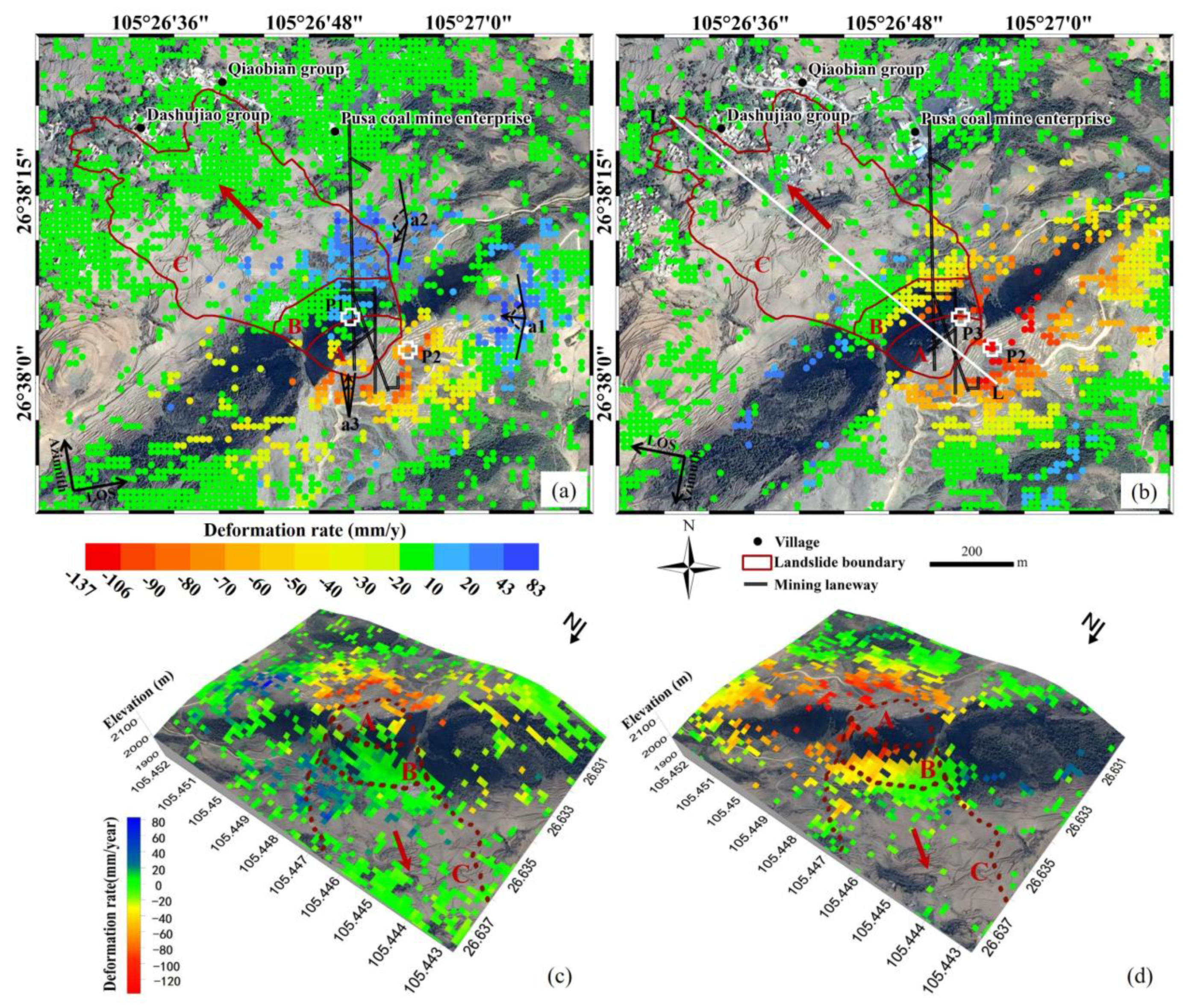
Annual LOS deformation rate maps calculated with ascending and descending Sentinel-1A/B images are shown in Figure 8a,b, respectively. It is worth noting that the negative values (red points) represent the surface moves away from the satellite, while the positive values (blue points) indicate the surface moves towards the satellite sensor. As the Pusa landslide is usually covered by dense vegetation, the interferograms within short temporal baselines were used to calculate the deformation rate by the stacking interferograms method. As shown in Figure 8, obvious deformation before the landslide was visibly seen at the trailing edge and eastern side of the sliding body (source area A). In source area A, many coherent points suffered large deformation, where the maximum deformation rate reached −106 mm/year in the line-of-sight (LOS) direction at the back scarp area of the landslide. It can be evidently seen that the eastern side of source area A showed a large deformation rate with the maximum rate of +83 mm/year. Besides, there was a large land subsidence area at the bottom of the whole slope. Furthermore, the average descending LOS deformation rates, shown in Figure 8b,d, were consistently larger than those from ascending datasets, but the signs were opposite in the eastern and bottom of the slope. Unfortunately, few points could be captured in source area A due to the layover for descending SAR geometry.

4.2.3. Decomposition of the Pre-Event Deformation

As we can see, different regions show different deformation values in ascending and descending results. It can be further divided into two cases from Figure 8: The deformations were both negative relative to two flight directions, and the deformations showed opposite signs relative to the different flight directions. Considering the different imaging geometries of the ascending and descending satellites, we deduced the relationships between the LOS deformation and actual slope direction deformation, shown in Figure 9. In this case, the average azimuth direction of the descending and ascending satellites was 190 ° 39 18 and 350 ° 06 54 , respectively. As for the first case, a point with deformation as negative in both ascending and descending deformation rate maps, the range of the actual slope deformation direction as for descending track result is shown as β 1 in Figure 9a, while the ascending track result is shown as β 2 . β is the intersection of β 1 and β 2 , which is shown as a red shadow, this range is the actual deformation direction for this case. After calculation, the moving direction of this area was approximately between 9 ° 53 06 ~ 10 ° 39 18 , which approximates north. Similarly, the actual deformation direction for the second case could also be inferred, as approximately between 190 ° 39 18 ~ 350 ° 06 54 , shown as β in Figure 9b. Finally, we put deformation in both cases in Figure 8a to decompose the pre-event deformation of the Pusa landslide and its neighbors. As for the points a1, a2, a3, the arc segments represent the range of actual deformation direction. The arrows represent the probable direction in these areas by combining it with the detected ALOS/PALSAR-2 pre-event deformation. The actual deformation direction of area a1 and a2 moved toward the center of the goaf, while the deformation of area a3 was well consistent with the factual sliding direction of the Pusa landslide. Therefore, the deformation inferred by InSAR measurements consists of two parts: coal mining-induced deformation and landslide deformation.

4.2.4. Pre-Event Deformation Time Series

Some previous research has shown that the sliding body suffered constant deformation before the landslide occurred [1,25,37,38]. To study the sliding mechanism of the Pusa landslide, we obtained the cumulative time series deformation of the landslide with the SBAS-InSAR technique. It can be seen in Figure 10 that the ascending InSAR measurements can be applied to capture the precursory deformation, as one SAR image was acquired just five days before the landslide occurred. To analyze the temporal evolution of the landslide deformation, we extracted the deformation time series at three points, which are marked as P1, P2, P3 in Figure 8a,b. P1 and P2 are located on the sliding body and back scarp area of the landslide, while the P3 is located on the top of the landslide. To better uncover the deformation trend, we conducted a curve fitting by using the Gaussian function for the deformation time series (Figure 10). For P1 in Figure 10a, the cumulative deformation can better reflect the deformation of the slope before the sliding. The sliding body showed slight LOS deformation since 3 October 2016, but the cumulative deformation of the slope body turned to a positive value after 13 April 2017. Moreover, it increased continuously and reached +116 mm by 23 August 2017, just 5 days before the landslide. For P2, it can also be seen that the deformation time series increased continuously for both ascending track (Figure 10b) and descending track (Figure 10d). The maximum deformation reached −106 mm and −120 mm, respectively. For P3 in Figure 10c, we can see the sliding body moved continuously before the landslide occurred with the maximum deformation of −86 mm.

5. Discussion

As there are no in-situ measurements one year before the failure of Pusa rock avalanche, the pre-event InSAR deformation time series can hardly compare quantitatively with external measurements. Even so, the InSAR deformation field can be verified by comparing different modes of ALOS/PALSAR-2 interferograms (Figure 7) and the stacking Sentinel-1 interferograms (Figure 8), where the deformed regions were consistent. Moreover, the deformation rate can be visually compared with ascending and descending Sentinel-1A images, shown in Figure 8, where green points indicate a stable region in ascending and descending results. And deformed regions can be verified by the Google earth image shown in Figure 2a before the event. Further, the deformation time series can be validated by ascending and descending results at P2 shown in Figure 10b,d, where the main deformation trends are consistent, and the difference has resulted from different SAR geometry.

5.1. The Triggering Factors

From Figure 3, six coal seams are located beneath the source region of the Pusa landslide, whose cumulative thickness is about 8 m [37]. To analyze the relationship between slope deformation, underground mining, and weather variations, we first compared the ascending deformation time series and deformation rate at point P1 with cumulated rainfall amounts in five days. The daily rainfall was logged by the Zhangjiawan Town rainfall station [1]. To synchronize the temporal resolution of InSAR measurements and rainfall, the deformation time series from 7 January 2017 to 23 August 2017 was selected to conduct the comparison (Figure 11). After April 2017, the Zhangjiawan Town area entered a period of sunny and rainy. The rainy season occurred in late June and the middle of July annually. It can be seen from Figure 11, the deformation of landslide body was affected by climate change, and the deformation between two adjacent heavy rainfall times could be roughly divided into three stages: I, II, III. The deformation of the source area accelerated after a large rainfall, namely stage I. Then, it entered the decreased rate, i.e., stage II, due to the sunny weather. Finally, the deformation rate kept constant under the continuous sunny weather, that is, stage III, which lasted until the next heavy rainfall. During late June and early mid-July 2017, persistent heavy rainfall took place in this area, and the cumulative rainfall increased quickly from 147.9 mm on 21 June to 522.2 mm on 21 July. Followed by persistent sunny days until the heavy rainfall occurred again on 24 August 2017. Accordingly, the slope deformation accelerated significantly after 15 July 2017. Then it began to decrease. Unlike the case in the former two periods, heavy rainfall occurred again on 24 August 2017, which would accelerate the slope deformation again according to the deformation law mentioned above. On the same day as the Pusa landslide occurred, it rained again and increased the weight of the slope body [15,39]. When stress exceeded the critical locking stress, the landslide eventually occurred at 10:30 local time, 28 August 2017.
Furthermore, mining may lead to surface deformation because the stress state was changed within the slope. According to the relevant research [25], the mining tunnels shown in Figure 8 were located 200–300 m beneath the landslide. The mining resumed production in early April 2017. Thereafter, mining was suspended four times before the landslide occurred, and the total closed time was 40 days. Finally, it was shut down on 17 August 2017. It can be seen from Figure 11 that the source area was stable before April 2017. Then it entered into the deformation stage, which indicates that underground coal mining was another triggering factor of the Pusa landslide.

5.2. The Failure Mechanism

Based on the aforementioned analysis, the mechanism of the Pusa landslide can be conceptualized in Figure 12 as follows. The original profile of the Pusa landslide is shown in Figure 12a. Figure 12b shows that the underground mining of the coal seams leads to the formation of goafs. The roof of the goaf loses the support from the rock mass below, so it will deform and subside by its gravity, which results in the surface settlement and tension cracks within a certain range. Once it enters the rainy days, the rainwater infiltrated into rock mass through these cracks in Figure 12c, which will increase the hydrostatic pressures, and decrease the strength of the soft rocks in the slope and undermine slope stability [25,40,41]. Besides, the study area is located on the east side on the Yungui Plateau, where the change in the temperature and long-term solarization will aggravate the fragmentation of rock mass, favorable to the rainfall infiltration. The factors of rainfall and temperature change lead to wetting–drying alternation and heating–cooling alternation, which accelerates the rock fragmentation [42]. Finally, the landslide occurs at the source region, based on the local geomorphologic conditions shown in Figure 12d.
Some previous studies have focused on rainfall-induced landslides [14,22], the similarity between these landslides and the Pusa landslide is that the rainfall infiltration will increase the hydrostatic pressures and decrease the strength of the soft rocks in the slope. But the particularity of Pusa landslide was the joint effect of underground mining and rainfall, which accelerated the process of deformation, especially under the karst environment.

6. Conclusions

The Pusa landslide was fully analyzed with SAR imagery in terms of the boundary and source area delineation, pre-event deformation monitoring, and triggering factors’ explanation. First, we manifested that coherence maps and SAR intensity maps generated by ALOS/PALSAR-2 images can be applied to identify the boundary and source area of the landslide. Second, the surface deformation can be uncovered by differential interferograms and the SBAS-InSAR technique by using both L-band ALOS/PALSAR-2 and C-band Sentinel-1A/B datasets. Moreover, the pre-event deformation time series was calculated by both ascending and descending Sentinel-1A/B datasets, which revealed that both underground mining-induced subsidence and unstable slope deformation jointly occurred. Third, two triggering factors, namely rainfall and underground mining, are uncovered by correlation analysis among the pre-event deformation time series, deformation rate variation, cumulative rainfall, and underground mining information. Moreover, the precursory deformation was clearly captured four months before the landslide event. Lastly, the failure mechanism of the Pusa landslide is summarized as four stages, which can be referred to as the rock avalanches in the southwestern of China.
Our research provides a systematic strategy for landslide early-warning in similar areas, such as the unstable slope identification by stacking interferogram method, deformation time-series monitoring by both ascending and descending SAR images. Moreover, the source area and the deposition area can be well measured with InSAR coherence maps and intensity maps for loss assessment. Otherwise, as for the combined effects of natural and anthropogenic factors to the rock avalanches, we suggest prevention measures should be developed in terms of rainfall data collection, real-time surface deformation monitoring, and geotechnical survey, especially caused by underground mining.

Author Contributions

L.C. and C.Z. performed the experiments and produced the results. L.C. drafted the manuscript. C.Z., C.Y., and Y.L. finalized the manuscript. Y.K., H.C., B.L., and A.X. contributed to the discussion of the results. All authors conceived the study and reviewed and approved the manuscript.

Funding

This work was supported by the National Key Research and Development Program of China (Grants No. 2018YFC1504805) and the Natural Science Foundation of China (Grants No. 41731066, 41874005, 41929001).

Acknowledgments

ALOS/PALSAR-2 data are provided by JAXA, Japan, Sentinel-1A/B data are freely downloaded from the website https://scihub.copernicus.eu/dhus/#home, and one arc-second SRTM DEM is freely downloaded from the website http://e4ftl01.cr.usgs.gov/MODV6_Dal_D/SRTM/SRTMGL1.003/2000.02.11/.

Conflicts of Interest

The authors declare no conflicts of interest.

References

  1. Fan, X.M.; Xu, Q.; Scaringi, G.; Zheng, G.; Huang, R.Q.; Dai, L.X.; Ju, Y.Z. The “long” runout rock avalanche in Pusa, China, on 28 August 2017: A preliminary report. Landslides 2019, 16, 139–154. [Google Scholar] [CrossRef]
  2. Huang, Q.H.; Cai, Y.L. Spatial pattern of Karst rock desertification in the Middle of Guizhou Province, Southwestern China. Environ. Geol. 2007, 52, 1325–1330. [Google Scholar] [CrossRef]
  3. Zhao, C.Y.; Zhang, Q.; Yin, Y.P.; Lu, Z.; Yang, C.S.; Zhu, W.; Li, B. Pre-, co-, and post-rockslide analysis with ALOS/PALSAR imagery: A case study of the Jiweishan rockslide, China. Nat. Hazards Earth Syst. Sci. 2013, 13, 2851–2861. [Google Scholar] [CrossRef] [Green Version]
  4. Mondini, A.C.; Santangelo, M.; Rocchetti, M.; Rossetto, E.; Manconi, A.; Monserrat, O. Sentinel-1 SAR amplitude imagery for rapid landslide detection. Remote Sens. 2019, 11, 760. [Google Scholar] [CrossRef] [Green Version]
  5. Raspini, F.; Ciampalini, A.; Conte, S.D.; Lombardi, L.; Nocentini, M.; Gigli, G.; Ferretti, A.; Casagli, N. Exploitation of amplitude and phase of satellite SAR images for landslide mapping: The case of Montescaglioso (South Italy). Remote Sens. 2015, 7, 14576–14596. [Google Scholar] [CrossRef] [Green Version]
  6. Yun, S.H.; Hudnut, K.; Owen, S.; Webb, F.; Simons, M.; Sacco, P.; Gurrola, E.; Manipon, G.; Liang, C.R.; Fielding, E.; et al. Rapid Damage Mapping for the 2015 M w 7.8 Gorkha Earthquake Using Synthetic Aperture Radar Data from COSMO–SkyMed and ALOS-2 Satellites. Seismol. Res. Lett. 2015, 86, 1549–1556. [Google Scholar] [CrossRef] [Green Version]
  7. Dai, K.R.; Xu, Q.; Li, Z.H.; Tomás, R.; Fan, X.M.; Dong, X.J.; Li, W.L.; Zhou, Z.W.; Gou, J.S.; Ran, P.L. Post-disaster assessment of 2017 catastrophic Xinmo landslide (China) by spaceborne SAR interferometry. Landslides 2019, 16, 1189–1199. [Google Scholar] [CrossRef] [Green Version]
  8. Horst, T.V.D.; Rutten, M.M.; Giesen, N.C.V.D.; Hanssen, R.F. Monitoring land subsidence in Yangon, Myanmar using Sentinel-1 persistent scatterer interferometry and assessment of driving mechanisms. Remote Sens. Environ. 2018, 217, 101–110. [Google Scholar] [CrossRef] [Green Version]
  9. Peng, M.M.; Zhao, C.Y.; Zhang, Q.; Lu, Z.; Li, Z.S. Research on Spatiotemporal Land Deformation (2012–2018) over Xi’an, China, with Multi-Sensor SAR Datasets. Remote Sens. 2019, 11, 664. [Google Scholar] [CrossRef] [Green Version]
  10. Kang, Y.; Zhao, C.Y.; Zhang, Q.; Lu, Z.; Li, B. Application of InSAR techniques to an analysis of the Guanling landslide. Remote Sens. 2017, 9, 1046. [Google Scholar] [CrossRef] [Green Version]
  11. Liu, X.J.; Zhao, C.Y.; Zhang, Q.; Peng, J.B.; Zhu, W.; Lu, Z. Multi-Temporal Loess Landslide Inventory Mapping with C-, X-and L-Band SAR Datasets—A Case Study of Heifangtai Loess Landslides, China. Remote Sens. 2018, 10, 1756. [Google Scholar] [CrossRef] [Green Version]
  12. Bouali, E.H.; Oommen, T.; Escobar-Wolf, R. Mapping of slow landslides on the Palos Verdes Peninsula using the California landslide inventory and persistent scatterer interferometry. Landslides 2018, 15, 439–452. [Google Scholar] [CrossRef]
  13. Zhao, C.Y.; Lu, Z.; Zhang, Q.; Fuente, J.D.L. Large-area landslide detection and monitoring with ALOS/PALSAR imagery data over Northern California and Southern Oregon, USA. Remote Sens. Environ. 2012, 124, 348–359. [Google Scholar] [CrossRef]
  14. Dong, J.; Zhang, L.; Li, M.H.; Yu, Y.H.; Liao, M.S.; Gong, J.Y.; Luo, H. Measuring precursory movements of the recent Xinmo landslide in Mao County, China with Sentinel-1 and ALOS-2 PALSAR-2 datasets. Landslides 2018, 15, 135–144. [Google Scholar] [CrossRef]
  15. Zhao, C.Y.; Kang, Y.; Zhang, Q.; Lu, Z.; Li, B. Landslide identification and monitoring along the Jinsha River catchment (Wudongde reservoir area), China, using the InSAR method. Remote Sens. 2018, 10, 993. [Google Scholar] [CrossRef] [Green Version]
  16. Liu, X.J.; Zhao, C.Y.; Zhang, Q.; Yang, C.S.; Zhu, W. Heifangtai loess landslide type and failure mode analysis with ascending and descending Spot-mode TerraSAR-X datasets. Landslides 2019, 17, 205–215. [Google Scholar] [CrossRef] [Green Version]
  17. Intrieri, E.; Raspini, F.; Fumagalli, A.; Lu, P.; Conte, S.D.; Farina, P.; Allievi, J.; Ferretti, A.; Casagli, N. The Maoxian landslide as seen from space: Detecting precursors of failure with Sentinel-1 data. Landslides 2018, 15, 123–133. [Google Scholar] [CrossRef] [Green Version]
  18. Shi, X.G.; Yang, C.; Zhang, L.; Jiang, H.J.; Liao, M.S.; Zhang, L.; Liu, X.G. Mapping and characterizing displacements of active loess slopes along the upstream Yellow River with multi-temporal InSAR datasets. Sci. Total Environ. 2019, 674, 200–210. [Google Scholar] [CrossRef]
  19. Zhao, C.Y.; Liu, X.J.; Zhang, Q.; Peng, J.B.; Xu, Q. Research on loess landslide identification, monitoring and failure mode with InSAR technique in Heifangtai, Gansu. Geomat. Inf. Sci. Wuhan Univ. 2019, 44, 996–1007. (In Chinese) [Google Scholar]
  20. Tantianuparp, P.; Shi, X.G.; Zhang, L.; Balz, T.; Liao, M.S. Characterization of landslide deformations in three gorges area using multiple InSAR data stacks. Remote Sens. 2013, 5, 2704–2719. [Google Scholar] [CrossRef] [Green Version]
  21. Bru, G.; Escayo, J.; Fernández, J.; Mallorqui, J.J.; Iglesias, R.; Sansosti, E.; Abajo, T.; Morales, A. Suitability assessment of X-band satellite SAR data for geotechnical monitoring of site scale slow moving landslides. Remote Sens. 2018, 10, 936. [Google Scholar] [CrossRef] [Green Version]
  22. Hu, X.; Wang, T.; Pierson, T.C.; Lu, Z.; Kim, J.; Cecere, T.H. Detecting seasonal landslide movement within the Cascade landslide complex (Washington) using time-series SAR imagery. Remote Sens. Environ. 2016, 187, 49–61. [Google Scholar] [CrossRef] [Green Version]
  23. Xu, Y.K.; Kim, J.; George, D.L.; Lu, Z. Characterizing Seasonally Rainfall-Driven Movement of a Translational Landslide using SAR Imagery and SMAP Soil Moisture. Remote Sens. 2019, 11, 2347. [Google Scholar] [CrossRef] [Green Version]
  24. Li, B.; Feng, Z.; Wang, G.Z.; Wang, W.P. Processes and behaviors of block topple avalanches resulting from carbonate slope failures due to underground mining. Environ. Earth Sci. 2016, 75, 694. [Google Scholar] [CrossRef]
  25. Zheng, G.; Xu, Q.; Ju, Y.Z.; Li, W.L.; Zhou, X.P.; Peng, S.Q. The Pusa rock avalanche on August 28, 2017 in Zhangjiawan Nayong County, Guizhou: Characteristics and failure mechanism. J. Eng. Geol. 2018, 26, 223–240. (In Chinese) [Google Scholar]
  26. Hanssen, R.F. Radar Interferometry: Data Interpretation and Error Analysis; Springer Science & Business Media: London, UK, 2001; pp. 96–97. [Google Scholar]
  27. Santoro, M.; Wegmüller, U.; Askne, J. Forest stem volume estimation using C-band interferometric SAR coherence data of the ERS-1 mission 3-days repeat-interval phase. Remote Sens. Environ. 2018, 216, 684–696. [Google Scholar] [CrossRef]
  28. Ulaby, F.T.; Moore, R.K.; Fung, A.K. Microwave Remote Sensing: Active and Passive, Volume III, From Theory to Applications; Artech House: Dedham, MA, USA, 1986. [Google Scholar]
  29. Lu, Z.; Meyer, D. Study of high SAR backscattering due to an increase of soil moisture over less vegetated area, its implication for characteristic of backscattering. Int. J. Remote Sens. 2002, 23, 1063–1074. [Google Scholar] [CrossRef]
  30. Lu, Z.; Dzurisin, D.; Jung, H.S.; Zhang, J.X.; Zhang, Y.H. Radar image and data fusion for natural hazards characterisation. Int. J. Image Data Fusion 2010, 1, 217–242. [Google Scholar] [CrossRef]
  31. Jiang, M.; Yong, B.; Tian, X.; Malhotra, R.; Hu, R.; Li, Z.W.; Yu, Z.B.; Zhang, X.X. The potential of more accurate InSAR covariance matrix estimation for land cover mapping. ISPRS J. Photogramm. Remote Sens. 2017, 126, 120–128. [Google Scholar] [CrossRef]
  32. Jiang, M.; Ding, X.L.; Hanssen, R.F.; Malhotra, R.; Chang, L. Fast statistically homogeneous pixel selection for covariance matrix estimation for multitemporal InSAR. IEEE Trans. Geosci. Remote Sens. 2015, 53, 1213–1224. [Google Scholar] [CrossRef]
  33. Adam, N.; Eineder, M.; Yague-Martinez, N.; Bamler, R. High resolution interferometric stacking with TerraSAR-X. In Proceedings of the 2008 IEEE International Geoscience and Remote Sensing Symposium (IGARSS 2008), Boston, MA, USA, 7–11 July 2008. [Google Scholar]
  34. Lyons, S.; Sandwell, D. Fault creep along the southern San Andreas from interferometric synthetic aperture radar, permanent scatterers, and stacking. J. Geophys. Res. Solid Earth 2003, 108, 2047. [Google Scholar] [CrossRef]
  35. Berardino, P.; Fornaro, G.; Lanari, R.; Sansosti, E. A new algorithm for surface deformation monitoring based on small baseline differential SAR interferograms. IEEE Trans. Geosci. Remote Sens. 2002, 40, 2375–2383. [Google Scholar] [CrossRef] [Green Version]
  36. Pepe, A.; Lanari, R. On the extension of the minimum cost flow algorithm for phase unwrapping of multitemporal differential SAR interferograms. IEEE Trans. Geosci. Remote Sens. 2006, 44, 2374–2383. [Google Scholar] [CrossRef]
  37. Ouyang, G.; Lan, Z.X. Construction Report Design of Collapse Geological Hazard Treatment Project of Pusa Coal Mine in Zhangjiawan Town, Nayong County; Guizhou Dikuang Engineering Investigation Corporation: Guiyang, China, 2009. (In Chinese) [Google Scholar]
  38. Ouyang, G.; Wang, J. Mining Landscape Environmental Protection and Reservoir Recovery Scheme of Pusa Coal Mine in Zhangjiawan Town, Nayong County; Guizhou Dikuang Engineering Investigation Corporation: Guiyang, China, 2010. (In Chinese) [Google Scholar]
  39. Liu, Q.C.; Xiong, C.R.; Ma, J.W. Study of Guizhou Province Guanling Daz-Hai Landslide Instability Process under the Rainstorm. Appl. Mech. Mater. 2015, 733, 446–450. [Google Scholar] [CrossRef]
  40. Fan, X.M.; Xu, Q.; Zhang, Z.Y.; Meng, D.S.; Tang, R. The genetic mechanism of a translational landslide. Bull. Eng. Geol. Environ. 2009, 68, 231–244. [Google Scholar] [CrossRef]
  41. Zhang, S.; Xu, Q.; Hu, Z.M. Effects of rainwater softening on red mudstone of deep-seated landslide, Southwest China. Eng. Geol. 2016, 204, 1–13. [Google Scholar] [CrossRef]
  42. Zhang, D.; Chen, A.Q.; Liu, G.C. Laboratory investigation of disintegration characteristics of purple mudstone under different hydrothermal conditions. J. Mt. Sci. 2012, 9, 127–136. [Google Scholar] [CrossRef]
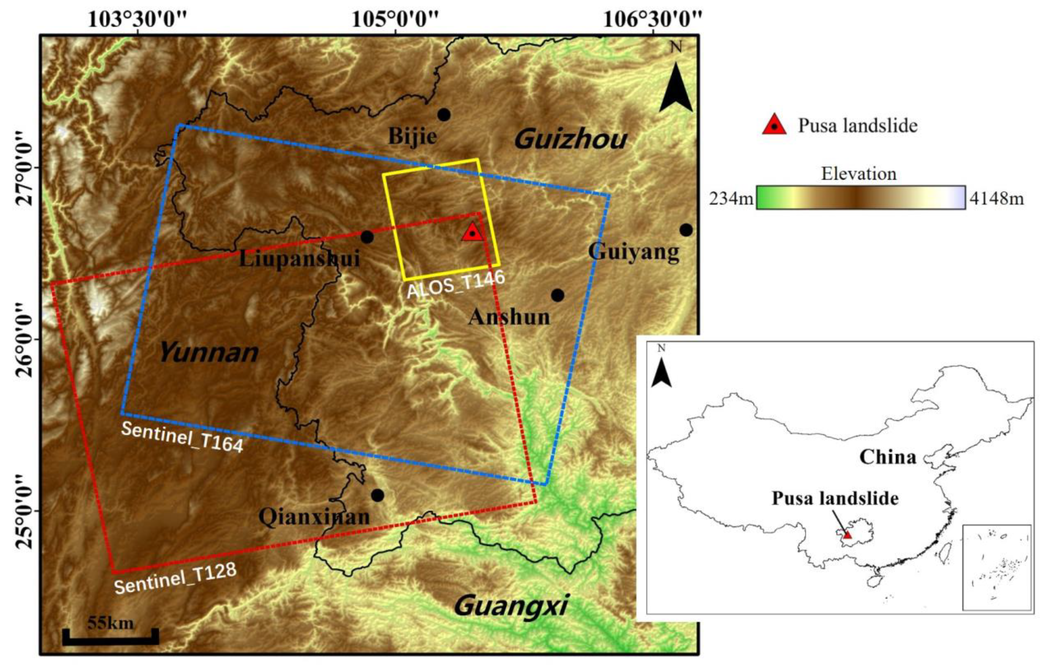
Figure 1. Study area and synthetic aperture radar (SAR) images coverage. The background is the shaded relief of the shuttle radar topography mission (SRTM) digital elevation model. The inset indicates the landslide location in China.
Remotesensing 12 00856 g001
Figure 2. The bird’s eye view of the Pusa landslide (revised from [1]). (a) The major sliding zones, including three sections, namely, A source area, B track-abrasion area, and C deposition area. (bd) are three on-site photos taken at positions shown in Figure 2a.
Remotesensing 12 00856 g002
Figure 3. The geological profile of the Pusa landslide along line L-L’ in Figure 2a. 1 Quaternary deposits; 2 Sandstone; 3 Mudstone; 4 Silty_mudstone; 5 Limestone; 6 Coal seam; 7 Fault; 8 Avalanche accumulation; 9 Source area; 10 Yelang Formation of the Lower Triassic; 11 Changxing–Dalong Formation of the Upper Permian; 12 Longtan Formation of the Upper Permian; 13 Coal mine tunnel.
Remotesensing 12 00856 g003
Figure 4. Baseline configurations of interferograms for ALOS/PALSAR-2 and Sentinel-1A/B SAR images. Triangles and lines represent SAR acquisition dates and interferograms, respectively. Red dash line indicates the date when the Pusa landslide occurred. (a) ALOS/PALSAR-2 interferograms. (b) Sentinel-1A/B interferograms.
Remotesensing 12 00856 g004
Figure 5. The flowchart for Pusa landslide analysis.
Remotesensing 12 00856 g005
Figure 6. The boundary and source area of the Pusa landslide identified by coherence and intensity maps from ALOS/PALSAR-2 images. (a) The pre-event coherence map, (b) the post-event coherence map, (c) the on-site image after landslide occurred, (d) and (e) the pre- and post-event SAR intensity maps acquired on 6 August 2017 and 12 November 2017, respectively, (f) the ratio between (d) and (e). It is noted that the color shown in (a) and (b) represent the coherence value. The white and yellow dash lines represent the landslide boundary, while the green line shows the source area. The black polygon shown in (d) and (e) represents the buried villages.
Remotesensing 12 00856 g006
Figure 7. Pre-event geocoded differential interferograms generated by ALOS/PALSAR-2 datasets. (a) The interferogram calculated by SM3 mode ALOS/PALSAR-2 data acquired on 4 September 2016 and 22 January 2017. (b–d) The interferograms calculated by SM1 mode ALOS/PALSAR-2 data, (b) 14 May 2017 vs. 11 June 2017, (c) 11 June 2017 vs. 6 August 2017, (d) 14 May 2017 vs. 6 August 2017. The red line indicates the landslide boundary, the black dash line indicates the deformation region.
Remotesensing 12 00856 g007
Figure 8. Average annual line-of-sight (LOS) pre-event deformation rate maps generated by ascending (a) and descending (b) Sentinel-1A/B SAR datasets. (c) and (d) are three-dimensional perspective view of (a) and (b), respectively. A-C represent different landslide zones. L-L’ represents the profile in Figure 3 and Figure 12. The black lines in (a) and (b) represent the mining laneway.
Remotesensing 12 00856 g008
Figure 9. SAR imaging geometries of the ascending and descending satellites. (a) The deformation of a surface point was negative relative to two flight directions. (b) The deformation of a surface point was positive and negative relative to two flight directions. Blue and brown represent descending and ascending tracks, respectively. β 1 and β 1 were the range of moving azimuth angle for the descending track. β 2 and β 2 were the range of moving azimuth angle for the ascending track. β and β were the intersections for the descending track and ascending track, respectively.
Remotesensing 12 00856 g009
Figure 10. Precursory deformation time series of the Pusa landslide for P1 ((a): ascending), P2 ((b): ascending, and (d): descending) and P3 ((c): descending). The ascending time series is from 3 October 2016 to 23 August 2017 with the reference SAR acquisition date on 3 October 2016, while the descending time series is from 29 September 2016 to 13 August 2017 with the reference SAR acquisition date on 29 September 2016.
Remotesensing 12 00856 g010
Figure 11. Comparison between cumulative deformation, cumulated rainfall amounts in five days, mining date, and deformation rate before the Pusa landslide occurred. The grey line indicates the date of resumption of coal mining, while the red line indicates the date of the landslide occurred. Shadow regions show different stages of deformation in the source area, which is influenced by weather variations.
Remotesensing 12 00856 g011
Figure 12. The conceptual failure mechanism of the Pusa landslide. The location of the profile is shown in Figure 2a and Figure 8b. (a) The initial state of the landslide. (b) Land subsidence and cracks occurrence on the surface with underground mining. (c) Temperature variation and rainfall aggravates the development of cracks, the colored points indicate the annual deformation rate along the profile calculated by descending Sentinel-1 datasets, shown in Figure 8b. (d) Profile after landslide event, including source section, track abrasion section, and deposition section.
Remotesensing 12 00856 g012
Table 1. The parameters of synthetic aperture radar (SAR) satellite images.
SensorALOS/PALSAR-2Sentinel-1A/B
Operation modeSM3SM1-
Orbit directionAscendingAscendingAscending/Descending
Heading (°)349.8349.8350.1/190.6
Incidence angle (°)40.639.744.0/33.9
Resolution (Range × Azimuth)4.3 m × 6.5 m2.9 m × 4.4 m9.3 m × 14.1 m
Number of images2520/18