Abstract
Ship detection in remote sensing has been achieving increasing significance recently. In remote sensing, ships are arbitrary oriented and the detector has to learn the object features of arbitrary orientation by rote, which demands a large amount of training data to prevent overfitting. In addition, plenty of ships have a distinct direction from the center point to the head point. However, little attention has been paid to the direction information of ships and previous studies just predict the bow directions of ships. In this paper, we propose to further exploit the ship direction information to solve the arbitrary orientation problem, including direction augmentation, direction prediction, and direction normalization. A Variable-Direction Rotated RoI Align module is designed for direction augmentation and normalization with an additional feature extraction direction as input. The direction augmentation method directly augments the features of ship RRoIs and brings great diversities to the training data set. The direction prediction introduces additional direction information for learning and helps to reduce noise. In the direction normalization method, the predicted ship directions are utilized to normalize the directions of ship features from stern to bow through the VDR RoI Align module, making the ship features present in one orientation and easier to be identified by the detector. On the L1 task of the HRSC2016 data set, the direction augmentation method and direction normalization method boost the RoI Transformer baseline from 86.2% to 90.4% and 90.6%, respectively, achieving the state-of-the-art performance.
1. Introduction
With the advances in object detection and remote sensing technologies, ship detection has come into wide use in military and civilian areas such as fishing management, illegal smuggling, and vessel surveillance [1,2,3]. Detecting ships accurately and efficiently in remote sensing images has also received great concern in recent years [4,5]. Wei et al. [6] proposed a novel ship detection method for high-resolution SAR imagery based on a high-resolution ship detection network. Wu et al. [7] proposed a new coarse-to-fine ship detection network (CF-SDN) that directly achieved an end-to-end mapping from image pixels to bounding boxes with confidences. Zhang et al. [8] presented a fast, regional-based convolutional neural network (R-CNN) to detect ships from high-resolution remote sensing imagery to avoid the influence caused by the sea surface model, especially on inland rivers and in offshore areas. Ship detection technology in remote sensing images belongs to the area of object detection. General object detection technology adopts horizontal bounding boxes to locate objects, which is suited for describing the natural objects in front views. However, in remote sensing images, ships are taken with bird views, presenting the character of being arbitrary oriented. Hence, horizontal bounding boxes cannot precisely describe ships, leading to the misalignments between ships and bounding boxes and the introduction of a large area of backgrounds. Moreover, when two rotated ships locate closely, describing ships by horizontal bounding boxes causes the problem of mistakenly eliminating the ship with lower confidence during non-maximum suppression. Rotated bounding boxes are then employed to locate rotated ships to solve the above questions, and we utilize rotated bounding boxes to detect ships in remote sensing images.
Current rotate object detection in remote sensing focuses on solving the problems of small objects, cluttered arrangements, discontinuous boundaries, angular periodicity, and so on, which distinguish the remote detection from general object detections. Rabbi et al. [9] proposed edge-enhanced, super-resolution GAN to improve the quality of remote sensing images for better small-object detection. Yang et al. [10] introduced a supervised multi-dimensional attention network, including channel attention and pixel attention, in SCRDet to enhance the ability to detect cluttered and small objects. Yang et al. [11] proposed Gaussian Wasserstein distance to convert rotated bounding boxes to 2D Gaussian distribution and approximate an in-differentiable, rotational IoU-induced loss to solve boundary discontinuity and its inconsistency. To deal with the angular periodicity problem, SCRDet [10] designed an improved smooth L1 loss by introducing an IoU constant factor and CSL [12] transformed angular prediction from a regression problem to a classification task. Qian et al. [13] designed a modulated loss and adopted eight-parameter regression to solve the loss discontinuity problem caused by discontinuous boundaries and angular periodicity. Zhong and Ao [14] decoupled the rotated bounding boxes to horizontal bounding boxes to overcome the sensitivity of IoU during box matching. Concerning the arbitrary orientations’ problem, rotated RRoI pooling [15] and rotated position sensitive (RPS) RoI Align [16] were proposed to extract features of rotated ships. However, the ship features still own two directions, from stern to bow and from bow to stern. Additionally, the ship detector needs to fit the two kinds of features.
In remote sensing, plenty of objects possess a direction from tail to head, such as airplanes, vehicles, and ships. Some studies [17,18] tried to predict the bow direction of ships, but never further exploited the direction information. In this work, we proposed to utilize direction information to handle the arbitrary orientations’ problem. Firstly, inspired by flip augmentation, we proposed direction augmentation to directly augment the feature of ships and send the augmented features for classification and regression, which skips the stages before feature wrap. The direction augmentation generates more data for the detector to fit the two kinds of features and helps to prevent overfitting. Secondly, normalizing the direction of ship features enables the detector to focus on the ship features of one direction, from stern to bow, for example. In this way, the learning task is simplified and the ship detector can better identify the ship features. Hence, we proposed to predict the direction and angle of ships and designed a Variable-Direction Rotated (VDR) RoI Align module to normalize the direction of ship features. The model structures and detection results of the proposed methods are shown in Figure 1. In the original model, the two aircraft carriers were omitted. The direction augmentation method detected the two aircraft carriers but located them inaccurately and scored low. The direction prediction method correctly predicted the bow direction of the two aircraft carriers. The direction normalization method located the two aircraft carriers accurately and scored high. The major novelties of the paper are concluded as follows.
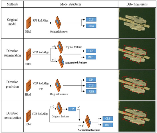
Figure 1.
The model structures and detection results of the proposed methods.
We designed a VDR RoI Align module to extract the RRoI features from a specific direction, which required an additional direction parameter, , as input compared with other RoI Align modules.
We proposed a direction augmentation method, which adopted the VDR RoI Align to augment RRoIs features with the opposite direction. Through the direction augmentation, the detector outputted two sets of predictions and the minimum loss of the two predictions was adopted to train the model. The direction augmentation brought diversity to training data sets and improved ship detection accuracy.
We designed a direction prediction module and found that the additional ship direction task improved ship detection accuracy slightly. However, a large weight of ship direction task made the detector hard to converge.
We proposed to normalize the ship direction information to boost the ship detector performance. The VDR RoI Align was adopted to extract and normalize the features of ships using the predicted ship directions. The normalized features were easier for the detector to identify compared with the original features of two possible directions.
On the L1 task of the HRSC2016 data set, the proposed direction augmentation and the direction normalization methods both achieved the state-of-the-art performance.
2. Related Works
2.1. Horizontal Detection
With the coming of the deep learning era, convolutional neural network (CNN) is widely investigated and applied to image classification [19], object detection [20], and image segmentation [21]. Girshick et al. [22] first introduced CNN for object detection in R-CNN and, since then, CNN has been playing a key role in object detection. Fast RCNN [23] sped up R-CNN by sharing the feature maps of images among different RoIs. Faster RCNN [24] replaced region proposal algorism [25] by region proposal networks (RPN), making the whole detector “end-to-end” and approximately real-time. To further accelerate object detection algorithms, single-stage object detectors were proposed. YOLO [26] divided feature maps into grids and directly predicted at each grid, to avoid the region proposal stage and save time. Over several years, YOLO developed to YOLOv4 [27] and reaches hundreds of FPS. Except for the breakthrough in model design, other investigations contribute tremendously to the improvement of detection accuracy and efficiency. Feature pyramid network [28] fused the features from top down and detected at different layers according to the size of objects. Oksu et al. [29] surveyed various imbalance problems and their corresponding solutions, including class imbalance, scale imbalance, objective imbalance, and spatial imbalance. Recently, transformer [30] was introduced to object detection task by DETR [31] and became a hot point. Swim transformer [32] reaches 58.7% mAP on the COCO data set and exceeds the highest accuracy of previous object detection works. The above works focused on nature image detection and adopted a horizontal bounding box to locate objects.
2.2. Rotated Detection
Horizontal bounding boxes fail to locate objects precisely in some scenes such as text detection and remote sensing, and rotated detection added an orientation parameter to describe arbitrary-oriented objects. Rotated detection is preliminarily popular in text detection. Ma et al. [33] first introduced rotated bounding boxes for arbitrary-oriented text detection based on rotation RPN. Zhou et al. [34] proposed an anchor-free detector and local-aware NMS to accelerate the detection pipeline. In remote sensing, Liu et al. [15] proposed rotated RRoI pooling to extract features of rotated ships in a rotated region-based CNN. Ding et al. [16] transformed horizontal bounding boxes to rotated bounding boxes by an RoI Learner instead of setting anchors of several orientations to reduce computational complexity. Apart from describing oriented objects by the center point, width, height, and orientation, Xu et al. [35] defined oriented objects by gliding the vertex of horizontal bounding boxes on each side, including eight parameters in total. Zhang et al. [18] adopted center point, head point, width, and heights to locate oriented objects. Qian et al. [13] described oriented objects by four corner points of rotated bounding boxes. In this paper, we adopted five parameters to locate oriented ships, including the abscissa of the center point, the ordinate of the center point, width, height, and orientation.
2.3. Data Augmentation
Data augmentation plays an important role in machine learning since it brings significant improvements to learning tasks, data augmentation, including geometric transformations, color space augmentations, and so on. During training, data augmentation enhanced the size and quality of training data sets, which helped to reduce the chance of overfitting. During testing, data augmentation provided more testing images for result fusion at the cost of consuming more inferring time. Hence, it is recommended to adopt various data augmentation technologies during training. However, when applying data augmentation during testing, we should make a trade-off between accuracy and efficiency. Being a simple but effective data augmentation method, flip operation exchanges the pixels of left and right or up and down in images, and then objects are moved to a different place of images. When applying flip operation during training, it flips the image in a specific probability, and the original image or the flip image would be sent to training. When applying flip operation during testing, the original and the flip images are fed for inference, costing twice the testing time of that without flip augmentation.
3. Proposed Methods
We proposed three methods to exploit direction information and deal with the arbitrary orientation problem for remote object detection, including direction augmentation, direction prediction, and direction normalization. We used the RoI Transformer detector [16] as our baseline to verify the effectiveness of the three proposed methods. RoI Transformer is a three-steps detector designed for rotated object detection in remote sensing images, including the proposal of HRoIs, the transformation from HRoIs to RRoIs, and the refinement of RRoIs. In the first step, the RPN takes the feature maps from the backbone as input and proposes HRoIs. In the second step, the RoI Transformer module transforms the proposed HRoIs to RRoIs. Finally, the refinement module classifies and regresses the features extracted from the RRoIs for better RRoIs. Our proposed methods worked in the refinement step, and the model structure of direction normalization is shown in Figure 2.
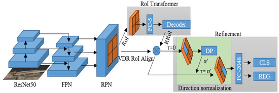
Figure 2.
The model structure of the direction normalization. The proposed direction normalization worked in the refinement stage, and denotes the feature extraction direction of the VDR RoI Align module.
For the RPN stage, suppose we obtained the HRoIs (), horizontal ground-truths (), and horizontal anchors (), where denotes the center point coordinate of the box and denotes the width and height of the box, the loss function of RPN can be written as:
where denotes the possibility of the anchor being a ship, and the ground-truth is labeled 1 if the anchor is positive or labeled 0. In Equation (2), includes and includes .
For the RoI Transformer stage, we, firstly, transformed obtained HRoIs () into RRoIs form (), where . Suppose we obtained RRoIs () and rotated ground-truths (), where denotes the orientation of the rotated box, then the loss function of RoI Transformer can be written as:
where denotes the possibility of the anchor belonging to one specific class, and the ground-truth denotes the class of the matched ground-truth boxes. The loss function of the refinement stage was the same as the RoI Transformer stage.
3.1. Variable-Direction Rotated RoI Align
In the RoI Transformer, the features of the RRoIs were extracted by Rotated Position Sensitive RoI Align after transforming HRoIs to RRoIs. The extracted features were, firstly, expanded into a column and then sent to FC layers for classification and location regression. FC layers are sensitive to locations, and the classification and regression results would change if the order of the feature column is inverted. For example, when extracting the features of ships, the features from bow to stern differ from those from stern to bow and would result in different predictions.
Therefore, we proposed the VDR RoI Align to extract features from a specific direction of ships. Different from previous RoI Align methods, the proposed VDR RoI Align demanded an additional feature extraction direction () as input. Consider an RRoI () and a feature-extracting direction , where () denotes the center of RoI and denote the width, height, and orientation. We divided the RRoI into bins. To transform the point in the rotated bins into the point in the vertical coordinate of feature maps, we adopted the following transformation:
where controls the direction correspondence of the two points. If , the VDR RoI Align is equal to RPS RoI Align methods and extracts the features from left-top to right-down. However, when , the feature extraction order is reversed and the features from right-down to left-top are attained. We adopted the channel mapping, which was the same as the original RPS RoI Align in RoI Transformer, and sampled two points in each bin. Bilinear interpolation was then employed to get the value of the transformed points.
3.2. Direction Augmentation
The VDR RoI Align module enabled us to extract the features of the Rotated RoI from any direction. Through the VDR RoI Align, we proposed a new augmentation method named direction augmentation, and the model structure of the direction augmentation is shown in Figure 3.
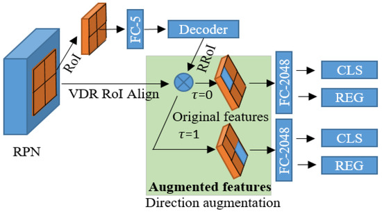
Figure 3.
The model structure of the direction augmentation (DA). In the VDR RoI Align module, is set to 0 and 1, respectively, extracting the ship features of opposite directions. The original features and augmented features are then used for classification (CLS) and regression (REG).
After transforming HRoIs to RRoIs, The VDR RoI Align module extracted the features of RRoIs two times, with set to 0 and 1, respectively, and outputted two features of the opposite directions. As shown in Figure 3, the augmented features had an opposite direction from the original features. The direction augmentation can be applied during both training and testing. During training, the two features were fed to FC layers for classification and regression, outputting two sets of predictions. Then, two loss functions were calculated between the ground-truths and the two sets of predictions. In the back-propagation stage, we could choose to optimize the detector by the loss of the original predictions, the minimum loss of the two sets of predictions, or the summary loss of the two sets of predictions. Adopting the direction augmentation during training provided more ship features of the opposite extraction directions for the classification and regression module to learn, reducing the chance of overfitting. During the testing stage, except for the original ship features, the augmented ship features were fed for classification and regression, and the two sets of detections were fused by NMS with an IoU threshold of 0.1. The direction augmentation during testing provided more data for the detector to test.
3.3. Direction Prediction
In the HRSC2016 data set [36], the head points of ships were labeled, providing the chance to improve the detector by using direction information. We further exploited direction information by predicting the direction of ships. When labeling the direction of ships, the ship direction was assigned to 0 if the head point of one object was located in the left of the center point and set to 1 if the head point sat in the right.
Figure 4 draws the model structure of the direction prediction. To predict the direction of ships, the features of RRoIs were extracted by the VDR RoI Align with , and were then sent to an FC layer, followed by the direction prediction, classification, and regression processes. The direction prediction module consisted of an FC layer with two output nodes, a softmax operation, and an argmax operation, and then generated the ship directions’ . During the training stage, Cross-entropy Loss was adopted to minimize the error between the predicted directions and ground-truth directions. The total loss function can be written as:
where denotes the ground-truth directions, denotes the predicted direction, and is the hyper-parameter to control the weight of the direction prediction task.
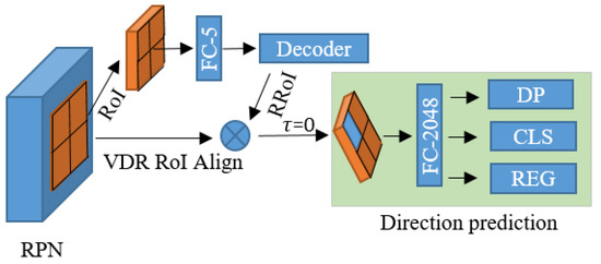
Figure 4.
The model structure of the direction prediction. The extracted features are used for direction prediction (DP), classification (CLS), and regression (REG).
Direction prediction was not first put out in our paper. In [17], the directions of rotated ships were represented by the orientation and direction , where and is a one-hot coding with four variables. They adopted an FC layer with output nodes to regress the direction , where denotes the class number of ships. We proposed to describe the directions of rotated objects by an orientation with the range of and a direction belonging to . Compared with [17], our direction prediction method was more efficient since we needed only an FC layer with two output nodes.
3.4. Direction Normalization
After obtaining the directions of ships, the direction information was utilized to normalize the direction of ship feature extraction, from bow to stern. As shown in Figure 5, we extracted the normalized features of RoI by VDR RoI Align with the feature extracting direction set to the predicted direction . The directions of the original ship features can be from bow to stern or from stern to bow, but the directions of the normalized ship features were all from bow to stern. Instead of the original features of RoI, the normalized features were used for classification and regression. Therefore, the model needed not to identify the ship features from bow to stern and was able to focus on extracting efficient features.
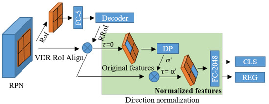
Figure 5.
The model structure of the direction normalization. The original features were used for direction prediction (DP), and the features’ extraction direction of the VDR RoI Align module was set to the predicted direction to extract the normalized ship features.
4. Experimental Results
We implemented the proposed methods based on the code of RoI Transformer (https://github.com/dingjiansw101/AerialDetection, accessed on 11 May 2021) and experimented with them on a server with GeForce 1080 and 8G memory. The model was trained on the HRSC2016 data set for 70 epochs with a batch size of 4. The learning rate started from 0.01 and decreased by 10 times at 50 and 60 epochs. ResNet50 serves as the backbone to extract feature maps from images with a size of , where denotes the length of the long side and denotes the length of the short side of images.
The HRSC2016 data set contains images with sizes ranging from to . There are three tasks in the HRSC2016 data set, including L1 task, L2 task, and L3 task. The L1 task categorizes all of the objects into “ship” class and is a one-class detection task. The L2 task categorizes all of the ships into four classes, consisting of the “ship”, “warcraft”, “merchant ship”, and “aircraft carrier” classes. The ship classes in the L3 task are more detailed, containing 18 classes. Previous studies [12,14,16,17,35] experimented on one-class detection on the L1 task of the HRSC2016 data set. In this paper, we categorized the ships into three classes according to the L2 task of the HRSC2016 data set. Apart from keeping the original “warcraft” and “aircraft carrier” classes, we categorized the “merchant ship” and the other “ship” classes into the “civil ship” class since they share similar shapes.
4.1. Evaluation Metrics
We adopted the mean Average Precession (mAP) and direction accuracy to evaluate the performance of the proposed methods quantitatively. The mAP is widely used to estimate the quality of object detectors, and the PASCAL VOC2007 metric was adopted to compute mAP. If the IOU between a prediction and a ground-truth exceeded 0.5 and they own the same class label, the prediction was assigned to True Positive (TP) or the prediction would be marked as False Positive (FP). The ground-truths without corresponding TP predictions were labeled as False Negative (FN). The precision and recall were calculated by:
If keeping only the predictions whose confidence exceeded a certain threshold, there would be different precession and recall under each threshold value. For the recalls’ range from 0 to 1.0, 11 points in total, AP was calculated by the average of precision under each recall, and mAP was the means of APs over all the classes. To evaluate the performance of the direction prediction module, we defined direction accuracy by the ratio of the TPs with the same direction as the corresponding ground-truths to all of the TPs.
4.2. Direction Augmentation
Flip augmentation is similar to the direction augmentation, so we compared the flip augmentation with the proposed direction augmentation to investigate the effectiveness of direction augmentation. Table 1 presents the results of flip augmentation and direction augmentation. The original loss, minimum loss, and summary loss represent without direction augmentation, minimum loss for direction augmentation, and summary loss for direction augmentation during training. Direction augmentation testing symbolizes whether to utilize direction augmentation during testing.

Table 1.
The detection mAP of direction augmentation. The bold is to highlight the highest mAP in the table.
From lines 3 and 5 of Table 1, the minimum loss for direction augmentation training brought an improvement of 3.06% mAP to the original model, higher than the gain of 0.92% mAP of the summary loss, and the minimum loss was, therefore, selected for direction augmentation training.
From lines 1, 2, 3, and 7, the flip augmentation, direction augmentation training, and direction augmentation testing could all boost the detection mAP, increasing by 1.47%, 3.06%, and 0.65%, respectively. From lines 3, 4, 7, and 8, direction augmentation training outperformed flip augmentation when they were used separately or combined with direction augmentation testing. From lines 3 and 9, the flip augmentation improved the behavior of direction augmentation training slightly, from 86.22% to 86.33%, and the improvement was less than the improvement of adopting flip augmentation only, from 83.16% to 84.63%. It can be explained that the flip augmentation shared similarities with the direction augmentation, so their improvements were coupled. From lines 1 and 10, when the flip augmentation, direction augmentation training, and direction augmentation testing were adopted simultaneously, the detection mAP reached the peak, rising from 83.16% to 86.92%. The set of ablation experiments demonstrated the effectiveness of the direction augmentation method.
During training, the flip augmentation cost 4.62% extra training time and the direction augmentation cost 5.28% training time. The model sizes of flip augmentation and direction augmentation were the same as the original model. During testing, we directly flipped the RRoI features for direction augmentation, costing 11.11% extra testing time.
The ground truths, detection results without direction augmentation training (line 1), and detection results with direction augmentation training (line 3) are shown in Figure 6, and the ships with a confidence lower than 0.4 were treated as background and removed.
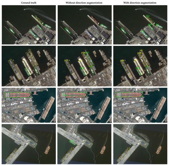
Figure 6.
The ship detection results of the model without and with direction augmentation training. The green bounding boxes denote civil ship and the yellow bounding boxes represent warcraft.
In the first row, the model without direction augmentation training missed three civil ships and the model with direction augmentation training detected the three ships with high confidence. In the second row, the model without direction augmentation training wrongly treated a warcraft as a civil ship and the model with direction augmentation training correctly identified the class of the warcraft. In the third row, the model without direction augmentation training located only half of a civil ship and the model with direction augmentation training located the entire civil ship. In the fourth row, the model without direction augmentation training mistook the background as a civil ship and the model with direction augmentation training identified and removed the background. The detection results of the model without and with direction augmentation proved the superiority of the proposed direction augmentation.
4.3. Direction Prediction
The highest direction accuracy and highest detection mAP under different weights of direction task are listed in Table 2. Only flip augmentation was adopted here. From Table 2, the direction prediction accuracy increased with becoming bigger and reached the highest 96.37% when . When , the model could not generate TP predictions and the direction accuracy was 0. The direction accuracy results presented that the weight of direction task benefitted direction accuracy, but when the weight became too large, the model failed to converge.
Table 2.
The direction accuracy and detection mAP under different . The bold is to highlight the highest mAP or accuracy in the table.
When was below 1, the ship detection mAP increased slightly with increases, indicating that the direction prediction task had a positive impact on the ship detection task. When exceeded 2, the detection mAP declined distinctly, and the model diverged when . The results revealed that the direction prediction task was feasible and boosted the detection mAP by 0.97%.
The ship detection results of adding the direction prediction task are shown in Figure 7, and the triangle direction denotes ship direction. It can be seen that most of the ship directions, including civil ship, warcraft, and aircraft carrier, could be correctly predicted.
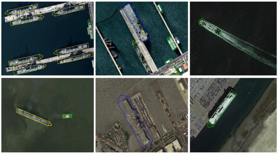
Figure 7.
The detection results of adding the direction prediction task.
4.4. Direction Normalization
The direction information was utilized to normalize the ship features and improve the ship detection accuracy. The detection mAP and corresponding direction accuracy under various are presented in Table 3. When setting to , it meant without direction normalization and the original features were used for ship detection. As listed in Table 3, the direction normalization boosted detection mAP, and setting to 1 brought a 3.38% improvement to the detection mAP. When smaller than 1, a larger brought more improvement to detection mAP. The detection mAP decreased when was larger than 1, and the model could not converge when , indicating that a too-large damaged other tasks such as classification and regression. The direction normalization cost 22.22% extra testing time than the model without direction normalization. The mAP results demonstrated the effectiveness of the direction normalization method.
Table 3.
The ship detection mAP and corresponding direction accuracy of the direction normalization. The bold is to highlight the highest mAP or accuracy in the table.
Figure 8 presents the ground truths, detection results of the original model (), and the detection results of direction normalization ().
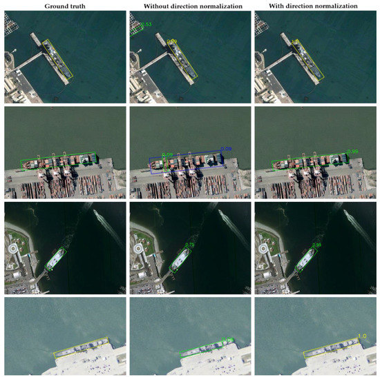
Figure 8.
The ground-truths and detection results of the model without and with direction normalization.
In the first row, the model without direction normalization mistook the background for a civil ship and the direction normalization model successfully removed the background. In the second row, the model without direction normalization wrongly regarded a civil ship as an aircraft carrier and the direction normalization model correctly identified the class of the civil ship. Furthermore, the direction normalization model located the ship more tightly. In the third row, the civil ship detected by the direction normalization model scored higher than that of the model without direction normalization. In the third row, the direction normalization model located the warcraft better than that without direction normalization. The results demonstrated the advantages of direction normalization over the original model.
To validate whether the normalized ship features benefited ship detection, we experimented on the direction of ship feature extraction based on the result of 88.22% detections, and the results are listed in Table 4. If setting the directions of ship feature extraction opposite to the predicted ship directions during testing, the detection mAP declined remarkably, as presented in the third row, from 88.22% to 84.15%. The results revealed that the detector preferred the normalized ship features extracted using the ship directions.
Table 4.
Detection results of different feature extraction directions. The bold is to highlight the highest mAP or accuracy in the table.
If removing the direction normalization and setting the feature extraction direction as random, the detection mAP reached 87.47%, as listed in the fourth row, which exceeded the results of by 2.71%. The two models both extracted the ship features in random directions during testing, but the direction normalization training performed much better than that of the original model, which indicated that the direction normalization training was capable of extracting better ship features.
We further experimented with the combination of direction augmentation and direction normalization. During testing, combining the normalized features extracted by the predicted ship directions and the opposite directions decreased the detection mAP from 88.22% to 87.96%, as listed in the fifth row. The detection precision declined from 51.08% to 44.78% because the detections using the opposite feature directions were included and they introduced plenty of False Positives. Meanwhile, the recall dropped off, meaning that the detections using the opposite directions made some True Positives abandoned. The results indicated that the direction augmentation and the direction normalization were mutually exclusive.
4.5. Comparasion with SOTA
We compared the proposed method with other SOTA methods on the L1 task of the HRSC2016 data set, and the results are listed in Table 5.
Table 5.
Performances of different methods on the HRSC2016 data set. DA denotes the direction augmentation and DN denotes the direction normalization. The bold is to highlight the highest mAP or accuracy in the table.
Our proposed direction augmentation and direction normalization were used to experiment on the RoI transformer baseline. On ResNet101 backbone, the direction augmentation boosted the detection mAP from 86.2% to 90.4%, and the direction normalization boosted the detection mAP from 86.2% to 90.6%. The performances of the proposed methods both exceeded the other state-of-the-art methods, demonstrating the effectiveness of utilizing ship direction information when detecting ships in remote sensing.
5. Discussion
Through comprehensive experiments and comparisons, the proposed methods that further exploit direction information were proven to be beneficial for ship detection. Inspired by flip augmentation, the direction augmentation was proposed to augment the features of ship RRoIs. When adopted during model training, direction augmentation cost 5.28% extra training time and did not influence the testing time, but increased the detection mAP from 83.16% to 86.22%, which was higher than an improvement of 1.47% caused by the flip augmentation. We then compared the similarities and differences of the two augmentation methods. Flip augmentation during training transported objects from one place to another place, and the ship directions were flipped meanwhile. The direction augmentation doubled the ship features with an opposite direction, and the features with a better prediction result were used for back propagations. The two augmentations could both exchange the ship feature directions, bringing great diversities to the training data set. The flip augmentation changed the location of ships, and the features for classification and regression may be different because the corresponding RoI generated by the RPN may change. However, the direction augmentation only flipped the feature direction, and the corresponding RoI remained the same. Furthermore, the direction augmentation chose the minimum loss features of the two directions for back propagations, while the flip augmentation randomly chose a direction. These factors distinguished the detection results of the direction augmentation from that of the flip augmentation.
To further prove the effects of direction augmentation, we adopted the COCO error analysis tools in mmdetetcion to rotated bounding boxes and compared the errors between the model without and with direction augmentation. The COCO error analysis tools adopted the PASCAL VOC2012 metric to calculate the mAP. Therefore, the detection mAP was higher than the previous results but kept the same tendency. Figure 9 shows the error analysis results of the model without and with direction augmentation.
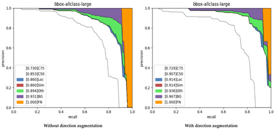
Figure 9.
The error analysis results of the model without and with the direction augmentation.
In Figure 9, “C50” denotes that the mAP was calculated under the IOU threshold of 0.5 when deciding TPs and FPs. “Loc” denotes the errors caused by localization, including the boxes classified correctly but localized incorrectly. The localization errors in the modes without and with direction augmentation were the same and took up merely 0.7% (0.860 minus 0.853). “Oth” denotes the boxes classified incorrectly. In the model without direction augmentation, 3.4% of the objects were classified incorrectly, but the objects wrongly classified decreased to 2.4% when applying the direction augmentation. “BG” denotes the backgrounds that were wrongly regarded as ships by the detectors and would reduce precision. The backgrounds in the model without direction augmentation caused a 3.7% reduction in detection mAP but descended to 3.1% when adopting the direction augmentation. Furthermore, the model with direction augmentation recalled 96.7% of the ships, but the model without direction augmentation omitted 6.9% of the ships. Therefore, the direction augmentation method helped to classify and recall ships.
Introducing an additional direction prediction task can slightly improve the detection mAP. It can be interpreted that the direction prediction task provided more prior knowledge and helped to eliminate noise, therefore preventing overfitting and improving the detection accuracy. The model diverged when the weight of the direction prediction task became too large. When setting to 1, the direction prediction loss accounted for over 80% of the total loss. Hence, setting to 5 was equivalent to enlarging the learning rate of the model by 4 times. A large learning rate can easily result in diverging, and the model, therefore, did not converge when exceeded 5.
Normalizing the feature extraction direction for ship detection boosted the detection mAP significantly, from 84.76% to 88.22%. It can be interpreted that the model could more easily distinguish the normalized ship features. Figure 10 shows the error analysis results of the models without and with direction normalization. The localization error in the model without direction normalization resulted in 2.30% mAP decreases, but the localization error in the direction normalization model was 1.00%. The localization errors revealed that the direction normalization could better locate ships and, therefore, caused fewer localization errors. In the models without and with the direction normalization, the class errors were 2.40% and 1.60%, respectively, indicating that the direction normalization could better classify ships. The model with direction normalization introduced fewer backgrounds than the model without direction normalization, 3.60% vs. 4.00%. On the other hand, the model with direction normalization recalled 97.70% of the ships, while the original model recalled 96.40% of the ships. In conclusion, the direction normalization method introduced fewer errors and recalled more ships, demonstrating that the normalized ship features benefitted ship detection.
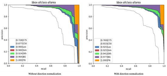
Figure 10.
The error analysis results of the model without and with the direction normalization.
The arbitrary orientations problem required the ship detection model to learn the ship features of various orientations. The direction augmentation augmented the ship features and provided more data for the model to learn. The direction normalization normalized and simplified the ship features, making the model easier to learn. The two methods were mutually exclusive but both benefitted detection.
6. Conclusions
In this paper, we proposed to exploit the ship direction information to handle the arbitrary orientations’ problem and improve ship detection accuracy, including direction augmentation, direction prediction, and direction normalization. This is the first paper that pays attention to the feature extraction direction of ships and utilizes the ship directions for ship detection. We designed a Variable-Direction Rotated RoI Align module to augment and normalize direction information, which required an additional input, to decide the direction of extracting RRoI features. Our main conclusions are as follows.
- (1)
- We proposed the direction augmentation method that augmented the RRoI features from the opposite feature extraction direction by the proposed VDR RoI Align module. The direction augmentation methods provided more data for the detector to fit the ship features of two possible directions. When applied during training, the direction augmentation improved detection mAP by 3.06%, while costing 5.28% extra training time.
- (2)
- We added a direction prediction task to predict the direction of ships, which helped to reduce noise and boosted ship detection accuracy by 0.97%. The ship direction accuracy reached the highest, of 96.37%, when setting the weight of the direction prediction task to 2.
- (3)
- We normalized the ship directions from bow to stern by inputting the predicted ship directions to the VDR RoI Align module when extracting the features of ship RRoIs. The normalized ship features were easier for the detector to identify compared with the original features of two possible directions. The direction normalization method boosted the ship detection mAP from 84.76% to 88.22%.
- (4)
- The direction augmentation and direction normalization achieved the mAP of 90.4% and 90.6% on the L1 task of the HRSC2016 data set, which significantly boosted the baseline performance and reached the start-of-the-art performance.
Author Contributions
Conceptualization, Z.T.; data curation, Z.Z.; funding acquisition, X.H. and J.G.; investigation, Z.Z. and T.X.; methodology, Z.T.; project administration, J.M.; resources, J.M.; software, Z.T.; supervision, X.H., J.G. and J.M.; writing, original draft, Z.T. All authors have read and agreed to the published version of the manuscript.
Funding
This research was funded by National Natural Science Foundation of China, grant number U1913602 and 61991412.
Conflicts of Interest
The authors declare no conflict of interest.
References
- Nie, T.; Han, X.; He, B.; Li, X.; Liu, H.; Bi, G. Ship Detection in Panchromatic Optical Remote Sensing Images Based on Visual Saliency and Multi-Dimensional Feature Description. Remote Sens. 2020, 12, 152. [Google Scholar] [CrossRef]
- He, H.; Lin, Y.; Chen, F.; Tai, H.-M.; Yin, Z. Inshore Ship Detection in Remote Sensing Images via Weighted Pose Voting. IEEE Trans. Geosci. Remote Sens. 2017, 55, 3091–3107. [Google Scholar] [CrossRef]
- Zhu, C.; Zhou, H.; Wang, R.; Guo, J. A novel hierarchical method of ship detection from spaceborne optical image based on shape and texture features. IEEE Trans. Geosci. Remote Sens. 2010, 48. [Google Scholar] [CrossRef]
- El-Darymli, K.; Gill, E.W.; McGuire, P.; Power, D.; Moloney, C. Automatic Target Recognition in Synthetic Aperture Radar Imagery: A State-of-the-Art Review. IEEE Access 2016, 4, 6014–6058. [Google Scholar] [CrossRef]
- Rostami, M.; Kolouri, S.; Eaton, E.; Kim, K. Deep transfer learning for few-shot SAR image classification. Remote Sens. 2019, 11, 1374. [Google Scholar] [CrossRef]
- Wei, S.; Su, H.; Ming, J.; Wang, C.; Yan, M.; Kumar, D.; Shi, J.; Zhang, X. Precise and robust ship detection for high-resolution SAR imagery based on HR-SDNet. Remote Sens. 2020, 12, 167. [Google Scholar] [CrossRef]
- Wu, Y.; Ma, W.; Gong, M.; Bai, Z.; Zhao, W.; Guo, Q.; Chen, X.; Miao, Q. A coarse-to-fine network for ship detection in optical remote sensing images. Remote Sens. 2020, 12, 246. [Google Scholar] [CrossRef]
- Zhang, S.; Wu, R.; Xu, K.; Wang, J.; Sun, W. R-CNN-Based Ship Detection from High Resolution Remote Sensing Imagery. Remote Sens. 2019, 11, 631. [Google Scholar] [CrossRef]
- Rabbi, J.; Ray, N.; Schubert, M.; Chowdhury, S.; Chao, D. Small-object detection in remote sensing images with end-to-end edge-enhanced GAN and object detector network. Remote Sens. 2020, 12, 1432. [Google Scholar] [CrossRef]
- Yang, X.; Yang, J.; Yan, J.; Zhang, Y.; Zhang, T.; Guo, Z.; Sun, X.; Fu, K. SCRDet: Towards more robust detection for small, cluttered and rotated objects. In Proceedings of the IEEE International Conference on Computer Vision, Seoul, Korea, 27 October–2 November 2019; Volume 2019. [Google Scholar]
- Yang, X.; Yan, J.; Ming, Q.; Wang, W.; Zhang, X.; Tian, Q. Rethinking Rotated Object Detection with Gaussian Wasserstein Distance Loss. arXiv 2021, arXiv:2101.11952. [Google Scholar]
- Yang, X.; Yan, J. Arbitrary-Oriented Object Detection with Circular Smooth Label. arXiv 2020, arXiv:2101.11189. [Google Scholar]
- Qian, W.; Yang, X.; Peng, S.; Guo, Y.; Yan, J. Learning modulated loss for rotated object detection. arXiv 2019, arXiv:1911.08299. [Google Scholar]
- Zhong, B.; Ao, K. Single-stage rotation-decoupled detector for oriented object. Remote Sens. 2020, 12, 3262. [Google Scholar] [CrossRef]
- Liu, Z.; Hu, J.; Weng, L.; Yang, Y. Rotated region based CNN for ship detection. In Proceedings of the International Conference on Image Processing, ICIP, Athens, Greece, 7 September 2018; Volume 2017. [Google Scholar]
- Ding, J.; Xue, N.; Long, Y.; Xia, G.-S.; Lu, Q. Learning RoI Transformer for Detecting Oriented Objects in Aerial Images. arXiv 2018, arXiv:1812.00155. [Google Scholar]
- Yang, X.; Sun, H.; Sun, X.; Yan, M.; Guo, Z.; Fu, K. Position Detection and Direction Prediction for Arbitrary-Oriented Ships via Multitask Rotation Region Convolutional Neural Network. IEEE Access 2018, 6. [Google Scholar] [CrossRef]
- Zhang, F.; Wang, X.; Zhou, S.; Wang, Y.; Hou, Y. Arbitrary-oriented ship detection through center-headpoint extraction. arXiv 2021, arXiv:2101.11189. [Google Scholar]
- Kene, Y.; Khot, U.; Rizvi, I. A Survey of Image Classification and Techniques for Improving Classification Performance. SSRN Electron. J. 2019. [Google Scholar] [CrossRef]
- Wu, X.; Sahoo, D.; Hoi, S.C.H. Recent advances in deep learning for object detection. Neurocomputing 2020, 396. [Google Scholar] [CrossRef]
- Minaee, S.; Boykov, Y.Y.; Porikli, F.; Plaza, A.J.; Kehtarnavaz, N.; Terzopoulos, D. Image Segmentation Using Deep Learning: A Survey. IEEE Trans. Pattern Anal. Mach. Intell. 2021. [Google Scholar] [CrossRef] [PubMed]
- Girshick, R.; Donahue, J.; Darrell, T.; Malik, J. Rich feature hierarchies for accurate object detection and semantic segmentation. In Proceedings of the IEEE Computer Society Conference on Computer Vision and Pattern Recognition, Columbus, OH, USA, 23–28 June 2014. [Google Scholar]
- Girshick, R. Fast R-CNN. In Proceedings of the 2015 IEEE International Conference on Computer Vision (ICCV), Las Condes, Chile, 11–18 December 2015; pp. 1440–1448. [Google Scholar]
- Ren, S.; He, K.; Girshick, R.; Sun, J. Faster R-CNN: Towards Real-Time Object Detection with Region Proposal Networks. IEEE Trans. Pattern Anal. Mach. Intell. 2017, 39. [Google Scholar] [CrossRef]
- Hosang, J.; Benenson, R.; Dollar, P.; Schiele, B. What Makes for Effective Detection Proposals? IEEE Trans. Pattern Anal. Mach. Intell. 2016, 38. [Google Scholar] [CrossRef]
- Redmon, J.; Divvala, S.; Girshick, R.; Farhadi, A. You only look once:unified, real-time object detection. In Proceedings of the 2016 IEEE Conference on Computer Vision and Pattern Recognition (CVPR), Las Vegas, NV, USA, 26 June–1 July 2016; pp. 779–788. [Google Scholar]
- Bochkovskiy, A.; Wang, C.Y.; Liao, H.Y.M. YOLOv4: Optimal Speed and Accuracy of Object Detection. arXiv 2020, arXiv:2004.10934. [Google Scholar]
- Lin, T.Y.; Dollár, P.; Girshick, R.; He, K.; Hariharan, B.; Belongie, S. Feature pyramid networks for object detection. In Proceedings of the 30th IEEE Conference on Computer Vision and Pattern Recognition, CVPR, 2017, Honolulu, HI, USA, 8–12 January 2017; Volume 2017. [Google Scholar]
- Oksuz, K.; Cam, B.C.; Kalkan, S.; Akbas, E. Imbalance Problems in Object Detection: A Review. In IEEE Transactions on Pattern Analysis and Machine Intelligence; IEEE: Piscataway, NJ, USA, 2020. [Google Scholar]
- Vaswani, A.; Shazeer, N.; Parmar, N.; Uszkoreit, J.; Jones, L.; Gomez, A.N.; Kaiser, Ł.; Polosukhin, I. Attention is all you need. In Proceedings of the Advances in Neural Information Processing Systems, Long Beach, CA, USA, 4–9 December 2017; Volume 2017. [Google Scholar]
- Carion, N.; Massa, F.; Synnaeve, G.; Usunier, N.; Kirillov, A.; Zagoruyko, S. End-to-End Object Detection with Transformers. In LNCS Lecture Notes in Computer Science; (including subseries Lecture Notes in Artificial Intelligence and Lecture Notes in Bioinformatics); Springer: Gewerbestrasse, Switzerland, 2020; Volume 12346. [Google Scholar]
- Liu, Z.; Lin, Y.; Cao, Y.; Hu, H.; Wei, Y.; Zhang, Z.; Lin, S.; Guo, B. Swin Transformer: Hierarchical Vision Transformer using Shifted Windows. arXiv 2021, arXiv:2103.14030. [Google Scholar]
- Ma, J.; Shao, W.; Ye, H.; Wang, L.; Wang, H.; Zheng, Y.; Xue, X. Arbitrary-oriented scene text detection via rotation proposals. IEEE Trans. Multimed. 2018, 20. [Google Scholar] [CrossRef]
- Zhou, X.; Yao, C.; Wen, H.; Wang, Y.; Zhou, S.; He, W.; Liang, J. EAST: An efficient and accurate scene text detector. In Proceedings of the 30th IEEE Conference on Computer Vision and Pattern Recognition, CVPR 2017, Honolulu, HI, USA, 8–12 January 2017; Volume 2017. [Google Scholar]
- Xu, Y.; Fu, M.; Wang, Q.; Wang, Y.; Chen, K.; Xia, G.S.; Bai, X. Gliding Vertex on the Horizontal Bounding Box for Multi-Oriented Object Detection. IEEE Trans. Pattern Anal. Mach. Intell. 2021, 43. [Google Scholar] [CrossRef] [PubMed]
- Liu, Z.; Yuan, L.; Weng, L.; Yang, Y. A high resolution optical satellite image dataset for ship recognition and some new baselines. In Proceedings of the ICPRAM 2017—6th International Conference on Pattern Recognition Applications and Methods, Porto, Portugal, 24–26 February 2017; Volume 2017. [Google Scholar]
- Yang, X.; Liu, Q.; Yan, J.; Li, A. R3Det: Refined single-stage detector with feature refinement for rotating object. arXiv 2019, arXiv:1908.05612. [Google Scholar]
- Fu, K.; Chang, Z.; Zhang, Y.; Sun, X. Point-Based Estimator for Arbitrary-Oriented Object Detection in Aerial Images. IEEE Trans. Geosci. Remote Sens. 2021, 59, 4370–4387. [Google Scholar] [CrossRef]


Publisher’s Note: MDPI stays neutral with regard to jurisdictional claims in published maps and institutional affiliations. |
© 2021 by the authors. Licensee MDPI, Basel, Switzerland. This article is an open access article distributed under the terms and conditions of the Creative Commons Attribution (CC BY) license (https://creativecommons.org/licenses/by/4.0/).