1. Introduction
A vessel traffic service (VTS) is an internationally recognized measure to ensure the proper level of navigation safety in coastal and heavy traffic areas. The history of VTS systems dates back to the 1940s [
1]. At the time, due to the end of military operations in the world’s maritime waters, the number of civilian vessels began to grow rapidly. Maritime administrations of coastal states stated that optical aids for navigation used would not ensure a proper level of navigation safety. As a result, measures were taken to monitor the movement of vessels using land radars and publicly available communication systems to transmit information to vessels about their mutual position. The first VTS system was established in 1948 in Douglas port on the Isle of Man. A few months later, the system appeared in Liverpool, and similar attempts were made in Rotterdam [
1]. In the 1950s, many of the largest ports in the world began launching coastal radar stations, the aim of which was and is to increase the level of shipping safety. However, it was only major sea disasters, such as the rocking of the Torrey Canyon (1967) tanker and the sinking of Amoco Cadiz (1978), that accelerated the legislative work that started in 1968. In 1985, the International Maritime Organization adopted Resolution A.578(14), the purpose of which was to define guidelines for the construction and operation of VTSs [
2]. The main tasks of modern vessel traffic surveillance systems are:
Ensuring a high level of safety in the waters covered by monitoring;
Increasing the efficiency of vessel traffic;
Protection of the marine environment.
In order for the VTS to fulfill its tasks, it is usually equipped with:
Contrary to marking systems, a VTS has the ability to interfere with the vessel’s movement through commands issued by maritime traffic controllers who supervise all vessels 24 h a day. One of the main sources of information about the vessel’s position, apart from the data received from shore radars, are data about its own position sent via radio by vessels to traffic control centers. At present, information about position is obtained from GNSSs, which, despite the growing threat to their functioning, as explained, e.g., in [
3], are the basic source of navigational information on vessels. Therefore, an extremely important element of the operation of vessel traffic surveillance systems is obtaining the most accurate and current position of the vessel at sea from the radar systems. For a position to be highly accurate, the process of determining the position must, on the one hand, be automated, and as much data as possible should be used to determine the co-ordinates of the position of the vessel at sea. This results in the need to adapt positioning methods known in other fields of science, e.g., in geodesy. Earlier publications of the authors indicate such a possibility, e.g., [
4,
5]. However, the problem with determining the highly accurate position of a vessel with the use of coastal radar stations is not only related to the acquisition of an excess number of position lines and the need for their rapid use, but is primarily related to the principle of operation of the navigation radar [
6,
7] and technical limitations of obtained observations from radar echoes. In [
8], the authors consider the problem of tracking multiple maneuvering targets in clutter. IMM/JPDA filtering and fixed-lag smoothing algorithms for multiple highly maneuvering targets in clutter can be used to estimate position, velocity, and acceleration, and, in [
9], the author presents a comparative study of two assignment alternatives, namely the JVC (unique association of a measurement with an existing track) and JPDA (nonunique association of a measurement with an existing track) algorithms, as efficient and reliable multiple-target tracking methods. These methods require the use of sophisticated data association, as well as positional estimation algorithms.
The scientific problem presented in our article shows how the position can be determined from simultaneous distance measurements obtained from several coastal radars.
The authors became interested in the problem of the quality of the radar observations used, e.g., measured radar distances to echoes, which are generated by very large vessels, e.g., MAERSK class container vessels [
10]. Earlier publications, e.g., [
11], defined the problem of radar distance measurement error using VTS edge radars, and, in order to eliminate it, approximation of the shape of the vessel’s hull with two geometric figures, a half ellipse and a rectangle, was proposed. However, this is not the correct approach to measuring the distance to the radar echo; therefore, this article generalizes the considerations made earlier in such a way that the radar echo is treated as an ellipse. The method of correcting the measured distance is presented below, together with the methodology of determining the co-ordinates of the vessel’s position. The considerations were checked in computer simulation conditions. A navigation and maneuvering simulator was used for the simulation, which allows for a relatively faithful recreation of the maneuvering elements of large container vessels [
12], as well as hydro-meteorological conditions, e.g., [
13].
2. The Gulf of Gdansk VTS System
The sea in which the research was conducted, the results of which are presented in this article, is the Gulf of Gdańsk. The Zatoka Gdańska VTS system is installed in this reservoir and the adjacent land areas. Its functionality corresponds to the international recommendations contained in the IMO Resolution [
2] and published by the IALA VTS Manual [
1]. In addition, the VTS duty service in the Gulf of Gdansk conducts:
- •
Supervision of the work of foreign and Polish research and development vessels;
- •
Supervision of specific sea tows;
- •
Supervision and co-operation in the framework of actions and events affecting the protection of the safety of navigation;
- •
Co-operation in the implementation of tasks related to NATO’s Naval Co-ordination and Guidance for Shipping (NCAGS).
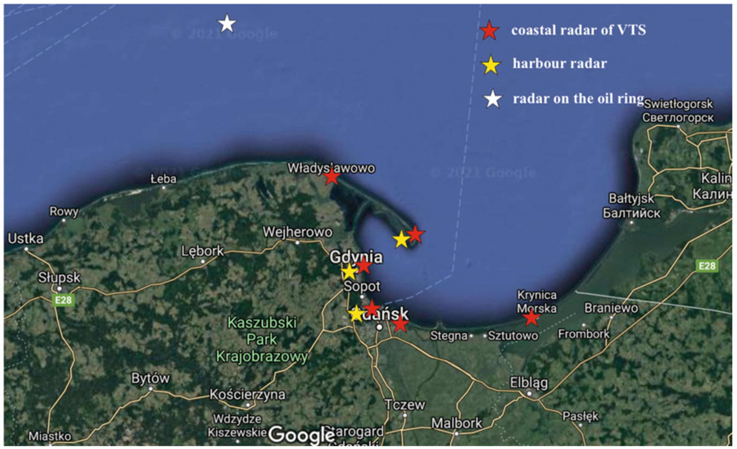
In the area of the Gulf of Gdansk, six shore radars are currently operating within the VTS system, which are located:
- •
In Wladyslawowo;
- •
At the lighthouse in Hel;
- •
On the tower of the Port of Gdynia Harbor Master’s Office;
- •
On the tower of the Harbor Master’s Office, Gdansk Northern Port;
- •
On the radar tower in Gorki Zachodnie;
- •
At the lighthouse in Krynica Morska.
Additionally, for traffic monitoring and management purposes, three port radars are also available:
- •
In Hel;
- •
In Gdynia;
- •
In Gdansk.
As the VTS system operates within the National Maritime Safety System (KSBM) [
14], which covers Polish territorial waters, the VTS Zatoka Gdańska system can also use the information provided by the radar located on the Baltic Beta oil rig. The locations of all radar stations are shown in
Figure 1.
The co-ordinates of the radar station antennas are presented in
Table 1.
The data obtained from radars are presented in the VTS Center on an electronic map in the form of radar echoes. The synthetic radar image consists of the fusion of several devices supplemented with the AIS overlay from the Polish chain of coastal stations [
15]. The basic means used for communication with vessels is the VHF communication system and DSC selective calling. The system uses six remote transceiver stations located at:
- •
Rozewie radio beacon;
- •
Hel radio beacon;
- •
Tower of the Harbor Master’s Office of Gdynia;
- •
Tower of the Harbor Master’s Office of Gdańsk;
- •
Krynica beacon;
- •
Long-range station located on the “Baltic Beta” oil rig.
Another tool supporting the work of operators is the long-range camera system (CCTV). The camera dedicated to the Gulf of Gdansk VTS is located at the Hel lighthouse, and its range is 7 nautical miles. The other five cameras support the duty services of the captain’s offices and boatswain’s offices. These cameras are located in the ports and marinas of:
- •
Hel;
- •
Gdynia;
- •
Gdansk New Port;
- •
Gdansk Northern Port;
- •
Gorki Zachodnie.
Detailed information on the VTS Gulf of Gdansk system is available on the website of the Polish maritime administration:
https://www.umgdy.gov.pl/ (the accessed date: 14 May 2021). Later in the article, however, the authors focus on the use of the radar subsystem presented in
Figure 1.
3. Model for Correcting the Radar Distance Taking into Account the Shape of the Vessel
In sea navigation, determining the mutual position of vessels with the use of radar is performed using the angle between the actual course line of the observed object and the bearing line made from the observed unit to the vessel [
16]. This angle is called an aspect. However, in the research problem described in this article, the aspect is defined as the angle at which the incoming radar wave hits an object [
16,
17]. We are, therefore, able to describe the effective reflection surface of the radar beam. For the purposes of further considerations, let us assume, similarly to [
11], that the aspect is the angle between the course line of the vessel observed in the VTS system and the vessel bearing line, determined from the coastal position of the radar station (
Figure 2).
We can obtain bearings and distances using the marine radar. When determining the radar bearing, good sea practice indicates that the observations are made at the center of the radar echo, which has a significant impact on the quality of the final determination. On the other hand, the distance measurement is carried out at the nearest edge of the echo, which creates an effective reflection surface (RCS). In the case of small vessels, the obtained distances are not affected by large errors, which significantly affect the final determination of the co-ordinates of the vessel’s position at sea. However, when observing radar echoes from large and very large vessels, it can often be seen that the measured distances refer to the nearest side of the vessel and not to the location of, for example, the position of the radar antenna, which should be considered as the vessel’s position. The location of the measurement is significantly different from the radar echo center, which has a significant impact on the final determination of the co-ordinates of the vessel’s position at sea [
18].
The element that has a significant impact on the accuracy of determining the position is the position in relation to the edge radar station, i.e., the vessel’s course in relation to the radar. Coastal radar stations are located along the coastline around the body of water. Each radar sweeps the vessel with its radar beam from a different angle. This has a significant impact on the accuracy of determining the distance or bearing of the radar to the observed vessel [
19]. On the other hand, the shape of the vessel also has a great influence on the accuracy of determining the position of the vessel. Modern watercrafts have very different shapes depending on their type and purpose or the degree of loading.
Typically, the radar image takes an ellipse-like shape, with the center being considered the vessel’s position. In further analyses, it was assumed that the co-ordinates of the ellipse center are the same as the co-ordinates of a vessel at sea. The vessel was approximated with an ellipse (
Figure 2). Such an approximation allows for a relatively precise adjustment of the real shape of the hull as a radar echo for the purposes of the model proposed in this article. In [
11], the authors assumed the vessel as a combination of a half ellipse and a rectangle; however, it seems that adopting the vessel as an ellipse generates a problem related to measuring the distance of very large vessels (e.g.,
).
Let us assume that in the half-horizon division system, the aspect
takes values
. Its value depends on the value of the true bearing determined from the position of the shore radar antenna to the vessel and the true course of the vessel, which can be expressed by the formula:
where:
—true bearing from coastal radar to vessel,
—true course of the vessel
Assuming that the model of the hull’s bow is a half ellipse, then the aspect is
. A graphic interpretation is presented in
Figure 3.
In addition, markings were introduced, where
is half the length of the vessel (large half-axis of the ellipse) and
is half the width of the vessel (the small half-axis of the ellipse).
Figure 3 shows the measured radar distance
and distance
by which the distance
has to be corrected in accordance with the assumption about the identity of the center of the ellipse with the position of the vessel in motion. The VTS operator is concerned with the actual location of the vessel and, therefore, the navigational observation from the radar distance measurement is defined as:
where
is the actual distance from the radar station to the vessel’s position.
To determine the distance
by which the radar distance should be corrected
, the ellipse equation should be used. Assuming, as in [
11], that the center of the local co-ordinate system coincides with the center of the ellipse, the ellipse equation takes the form:
The radar beam bounces off the hull at point
, so its polar co-ordinates
can be expressed in the following way:
Inserting dependences (4) to (3) we get:
Hence, after transformations we get:
By using the dependence
, we obtain a formula for determining the distance between the edge of the echo to which the distance was measured and the center of the ellipse:
The above dependence is fulfilled if we consider the measurements of distances for which the value of the angle is .
Assuming that the model of the aft part of the hull is also a half ellipse, with axes equal to half the length of the vessel and the width of the vessel, two variants should be considered:
- •
When the radar beam hits the vessel’s side (
Figure 4);
- •
When the radar beam strikes the stern of the vessel (
Figure 5).
Such details can take into account different shapes of the sterns of vessels depending on their types.
In the first case presented in
Figure 4, let us introduce angle
as
, and then, using the law of sines, we get:
However, in the second case, when the distance is measured to the stern of the vessel (
Figure 5), we use the law of cosines. The moment at which the law of cosines is to be used determines the value of angle
(
Figure 4). The value of this angle is determined from the dependence:
Then, it can be assumed that the threshold value of the aspect
, above which the law of cosines is used, can be expressed as follows:
For measurements of the stern section angle
(
Figure 5), the value of the corrected distance is calculated from the law of cosines:
Analyzing the above-described three cases of measuring the radar distance from the shore station to the vessel as a function of its course (hull position) in relation to the radar antenna, we obtained a mathematical model for determining the distance
, by which the measured radar distance should be corrected:
where:
—half of the vessel’s length;
—half of the vessel’s width.
4. Analytical Determination of the Vessel’s Position with the Use of Redundant Observations
Since the end of the 20th century, marine navigation has been dominated by automated positioning systems. In practice, this means that, in the process of acquiring navigational observations, we can use a larger number of observations. A large number of observations (greater than the number of designated co-ordinates) requires the use of analytical positioning methods that are well known (e.g., in geodesy) and described in the subject-related literature, e.g., [
20,
21,
22]. One of the methods previously used by the authors is the method of least squares. This method can easily take into account the position determined in the navigation and, using the available observations, can determine the co-ordinates of the vessel’s position at sea by determining the shift of the observed position in relation to the position. Therefore, the LSc method was used in test, which is described below.
In the research problem under consideration, we assume that we have at our disposal navigational information from the measurement of the radar distance. Let us assume that the two-dimensional position of the vessel is determined
. The position co-ordinates are included in the vector
. In addition, in accordance with the generally accepted rules for creating systems of observational equations described in [
20], we created a system of observation equations:
where
is a vector of radar observation,
is understood as a vector of radar observation corrections, and vector
is a vector of random errors of observation of the covariance matrix
and a vector of expected values
. If it is assumed that the radar antenna is located at a position (e.g., in the center of the ellipse described above) that is assumed as the vessel’s position with known approximate co-ordinates, then vector
can be created along with vector
:
Quantity
is a vector of unknown co-ordinate increments to the approximate position in such a way that
. Moreover, let us assume that the matrix:
is a known matrix of coefficients, whereas the matrix:
is a free terms vector. In such a case, we can create a calculus applied in geodesy [
20], namely the adjustment calculus expressed as follows:
where:
—vector of corrections to the observations made;
—covariance matrix of the results of the observations;
—known matrix of cofactors;
—unknown variance coefficient;
—weight matrix for the observations made.
The classic form of the adjustment calculus allows us to present the following solution: , and the finally aligned co-ordinates of the ship’s position can be obtained from the dependence, .
5. Experiment Validation
The adopted theoretical assumptions were tested based on real ship traffic registrations, which were made at the VTS Gulf of Gdansk Maritime Safety Center. The results of one of the tests, which are representative for the discussed research problem, are presented below. The test involved the registration of the passage of the vessel Frederik (
Figure 6) to the container terminal in Gdynia. The test presented in this article relates to the approach to the port that took place on 17 February 2017 at 11:57 AM. The container ship was moving on the approach fairway between the buoys “GN” and “GD” to the port of Gdynia, with variable speeds in the range
. The vessel moved on a true course in the range
. In the conducted analyses, it was assumed that the vessel was moving along the course
.
The test used a measurement structure that included four coastal radar stations (Hel_LM, Gdynia_NW, Gdansk_KPP, Gdansk_GZ), the schematic locations of which are shown in
Figure 6. The co-ordinates of their distribution are shown in
Table 1. The dimensions of the container ship necessary for further analysis are
and
, so it was assumed that
and
.
From the coastal radar stations, four radar distances were measured (
Table 2) to the vessel, which was in the approximate position
,
. The process of determining the position was carried out with a rectangular flat system; therefore, the geographical co-ordinates were converted, and the following values were obtained:
,
. Moreover, it was assumed that the error of determining radar observations for all distances was the same [
23,
24]
.
In addition, to determine the aspect
, true bearings for the vessel were obtained from coastal radar stations, the values of which are given in
Table 3.
First, to determine the angle of incidence of the electromagnetic wave (radar signal) on the hull (
Figure 4,
Figure 5 and
Figure 6), the values of aspect
were determined. According to Equation (1), the following results were obtained:
- •
For the radar station Hel_LM:
- •
For the radar station Gdynia_NW:
- •
For the radar station Gdańsk_KPP:
- •
For the radar station Gdańsk_GZ:
Subsequently, according to dependence (12), corrections to the measured distances for individual angle values were determined:
- •
For within the range: , the correction to the measured distance from Hel_LM station is ;
- •
For within the range: , the correction to the measured distance from Gdynia_NW station is ;
- •
For within the range: , the correction to the measured distance from Gdansk_KPP station is ;
- •
For within the range: , the correction to the measured distance from Gdansk_GZ station is .
The correct values of the measured radar distances from the VTS coastal radar stations are presented in
Table 4.
In extreme cases, the values of the corrected distances , in relation to the measured distances differ by 12.53 m (for Gdańsk_KPP) and by 54.82 m (for Gdynia_NW).
The proposed model of correcting the measured radar distance from the VTS system station allows for more effective use of the observations made using the methodology proposed in the article. As a result, corrections to the measured observations can be determined more precisely. For comparison, using adjustment calculus (17), the vessel’s co-ordinates were determined using the measured radar distances , and by determining the co-ordinates of the vessel using corrected radar distances . As mentioned, the error of determining radar observations for all distances is the same . The corrected distances significantly influenced the form of the free terms matrix :
This had a large impact on the determination of the estimated vessel’s position and the values of errors in its determination:
Ship’s position determined for the measured radar distances :
with the mean error of the determined ship’s position ;
Ship’s position determined for the corrected radar distances :
with the mean error of the determined ship’s position .
6. Conclusions
For many years to come, modern navigation radars will remain the basic tool for the observation of sea areas monitored by vessel traffic surveillance systems. The development of technology makes it possible to obtain information simultaneously about mobile objects from many radar stations. However, the use of acquired information without necessary processing leads to ambiguous results, such as multiple radar echoes or not taking into account the dimensions of vessels when measuring the radar distance to the edge of the echo. Therefore, easy and automated methods should be used to solve the problem of ambiguity in determining the co-ordinates of the vessel’s position at sea. The results of the research described in this article present one of the possible ways of eliminating these inconveniences.
The developed analytical method of correcting the measured radar distances allows a reduction in the observations made from many coastal radars to one point. Maritime practice indicates that the measurement of radar distances should be made at the nearest edge of the observed echo. If the method proposed in the article is used, the problem of not taking into account the vessel’s size is also solved, because the differences in determining the vessel’s co-ordinates, resulting from the fact that the position of the radar echo edge is not the same as the vessel’s position, are significantly eliminated. The adopted generalization that the radar echo approximates the shape of an ellipse allows the use of analytical solutions for vessels of any shape.
Simultaneous correction of available navigational observations (in the article—radar distances) and the use of modern methods of adjustment known in geodesy allow for more precise determination of the observed position, which is extremely important in areas with high traffic.


