Article

Subsidence Monitoring Base on SBAS-InSAR and Slope Stability Analysis Method for Damage Analysis in Mountainous Mining Subsidence Regions

1
Institute of Remote Sensing and GIS, Peking University, Beijing 100871, China
2
Northern Shaanxi Mining Zhangjiamao Co. Ltd., Shenmu 719300, China
*
Author to whom correspondence should be addressed.
Remote Sens. 2021, 13(16), 3107; https://doi.org/10.3390/rs13163107
Submission received: 3 June 2021 / Revised: 29 July 2021 / Accepted: 30 July 2021 / Published: 6 August 2021

Abstract

:
Surface subsidence caused by coal mining has a great impact on the geological and ecological environments and causes damage to houses, roads, and industrial buildings. In order to understand the subsidence pattern in the mountainous mining regions, three mining faces of the Zhangjiamao mining area in the north of Shaanxi province, northwestern China are taken as case study. Firstly, the small baseline subset (SBAS) technology is used to process 12 images obtained in the mining area to investigate the subsidence data from December 2019 to April 2020. The boundary of surface deformation of the mining area interpreted by the SBAS-InSAR technology is inconsistent with the theoretical boundary suggested by coal mine subsidence theories. Especially, there are some areas in which the real subsidence are larger than estimated area. This discrepancy must be corrected as steep slopes near the theoretical boundary may increase the likelihood of landslides. Our research indicates that: (1) The accumulated displacement and the maximum deformation rate reached −120.759 mm and −270.012 mm/yr in the study area, and the subsidence boundary of the three mining faces is revealed; (2) the combination of the predicted boundary and slope stability analysis can effectively identify the landslide region at the edge of subsidence boundary; (3) the field surveys have proved the effectiveness of this method. The mining area subsidence revealed by our research helps to further understand the impact of land subsidence caused by mining in the mountainous areas and provides a practical method to predict subsidence boundaries and the likelihood for landslides.

Graphical Abstract

1. Introduction

Coal is the most important basic energy to support the development of China’s national economy and ensure people’s livelihood [1]. However, coal mining causes various environmental problems, such as land subsidence, damage to the water and soil environment, mining waste disposal, and air pollution. Most of the mining areas in the north of Shaanxi Province in northwestern China are in the Loess Plateau, where the gully can be seen everywhere cause by the ancient rivers’ erosion. Due to the poor surface vegetation, serious soil and water loss, and high-density and deep-cut gullies, landslide and collapse are easy to occur in these regions [2]. This causes serious damage to the ecology and environment of the mining area and even threatens the life of the local residents [3,4]. Therefore, timely monitoring and effective analysis of the surface subsidence of the mining area is essential to the environmental governance, mining area reclamation, and protection of the safety of the residents in the mining area.
The traditional methods for monitoring surface subsidence in mining areas mainly include leveling, total station measurement, and GPS measurement. However, these techniques also have disadvantages—such as heavy workloads, high costs, and difficulty in accurately distinguishing the subsidence range [5]. With the development of satellite remote sensing technology in recent years [6,7], differential interferometry synthetic aperture radar (D-InSAR) can realize large-scale and all-day monitoring, and significant results have been obtained in the research of surface deformation monitoring. However, the application of this method in mining areas suffers from some errors such as time–space incoherence and atmospheric effect [8]. To overcome the limitations of D-InSAR, a small baseline subset (SBAS) technique was proposed in the time series analysis technology of SAR [9]. Recently, SBAS-InSAR technology has been widely used in mining subsidence monitoring [5,10,11,12,13,14,15], and the performance of SBAS-InSAR technology has been proved. This technology can effectively reduce the influence of spatiotemporal incoherence and atmospheric effect. Also, it can monitor the deformation of time sequence of the surface with an accuracy up to millimeter level [16].
Scholars have done a lot of research on slope slippage and collapse caused by underground mining. Yang Jun et al. investigated the impact of mining landslides on surrounding buildings by using the deformation characteristics of SBAS-InSAR technology [17]. Xinpeng Diao et al. evaluated the building’s damage in mountainous mining regions by combining the subsidence theory and slope stability analysis method [12]. Based on the slope stability analysis of loess gully collapse, Chi Mu et al. provided a scientific basis for effective prevention and control of geological disasters in Shendong Mining Area [18]. Xugang Lian et al. analyzed the slope stability caused by longwall mining based on real-time monitoring with global navigation satellite systems (GNSS) [19]. However, due to the complexity of mining subsidence, reliable prediction of mine-induced subsidence remains a challenge [20]. Especially, the existence of numerous interrelated factors, such as the rock masses characteristics, the ground surface topography, the natural precipitation, and the method of coal mining make the subsidence analysis complicated [20]. As for the mountainous area of northern Shaanxi in China, there are thousands of gullies and hills. The existing subsidence method cannot predict the impact of secondary damage such as landslides caused by mining subsidence, and it is difficult to estimate the boundary of mining influence accurately due to loess topography. Previous studies have rarely addressed these issues.
In order to obtain the subsidence pattern of the study area and reveal the influence of landslide on edge of the subsidence range, this paper first obtains the InSAR time series subsidence data of the mining area from December 2019 to April 2020. Meanwhile, it uses the SBAS-InSAR technology to analyze the surface subsidence in this study area and reveals the temporal and spatial subsidence pattern of this mine area. Then, by comparing the actual surface subsidence boundary interpreted by the SBAS-InSAR technology with the subsidence boundary predicted by the probability integral method, we found that the predicted subsidence boundary was not consistent with the actual subsidence boundary. Therefore, we analyzed the effect of slope stability on boundary of mining activities and our further research and field survey estimation result was coincide. This study provides guidance and reference for future research on the subsidence caused by mining and land reclamation evaluation in the mountain area of northern Shaanxi.

2. Study Area

The Zhangjiamao mining area is located in the north of the middle of Shenmu County, Shaanxi Province, northwestern China and it is about 36 km away from downtown of Shenmu city. The elevation of the mining area is generally high in the southwest and low in the northeast. Specifically, the highest elevation of this area is 1341.0 m, and the lowest elevation is 1005.6 m, with a maximum elevation difference of 335.40 m.
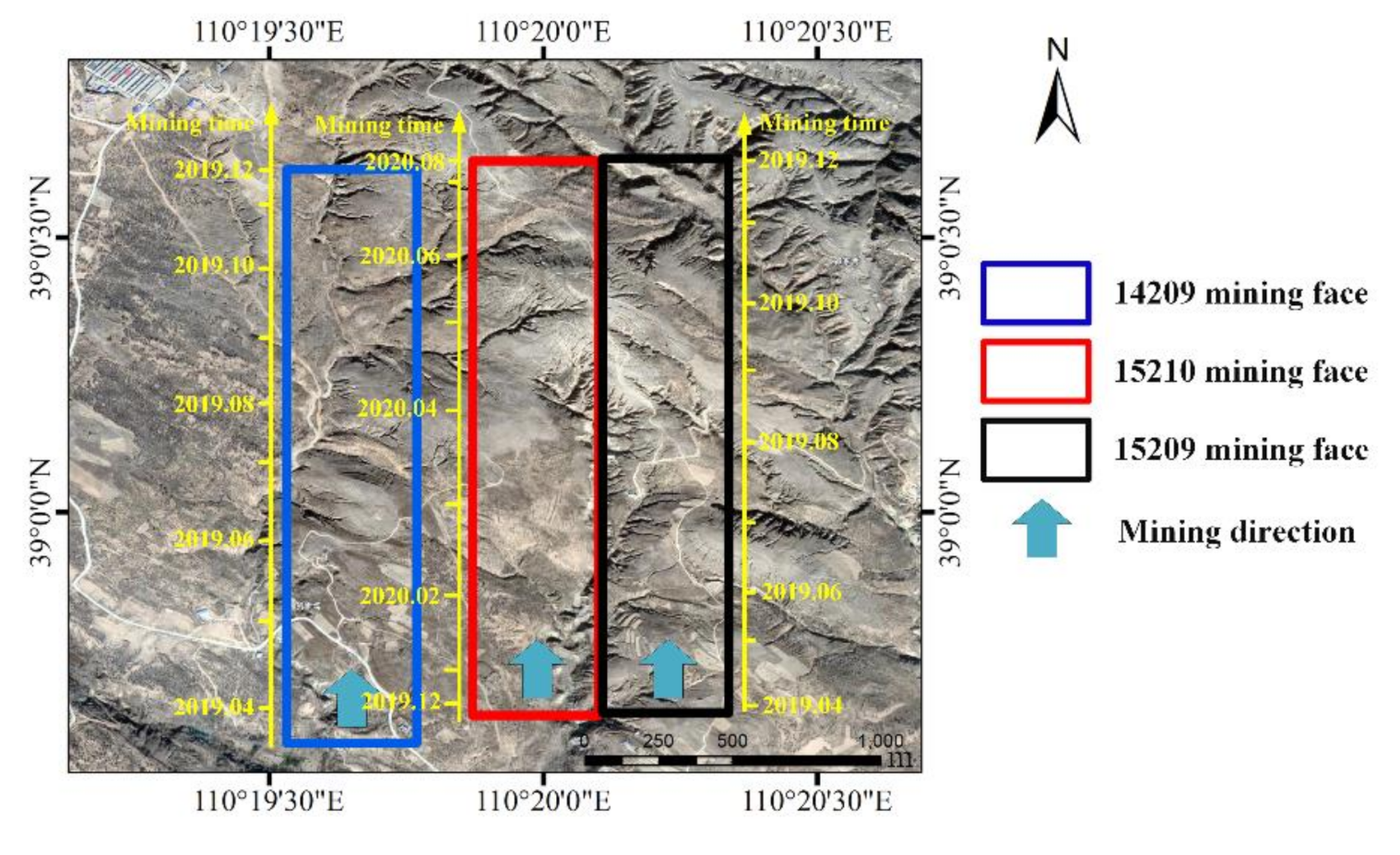
The landform types of the mining area can be divided into loess hilly and gully area. Landslide and ground fissure are most common geological disasters resulted from the underground coal mining activities, seen in Figure 1d (the maximum gap of the ground fissure is 3.6 m, the maximum gap of the ground fissure is 0.1 m). The study area includes the 14209, 15209 and 15210 mining faces of Zhangjiamao coal mine. The total inclination length of the three mining faces is 895 m, and the strike length of the three mining faces each is 1915 m, 1860 m, and 1860 m. According to the data, the 15209 mining face started mining in May 2019 and the mining activity ended in December 2019. The 15210 mining face started mining in December 2019 and the mining activity ended in August 2020. The 14209-mining face started mining in February 2019. The mining activity ended in November 2019 in the north of the study area, the residents have been relocated in advance, and there are no other buildings on the mining face. In addition, there are no rivers, reservoirs and other water bodies.
The basic parameters of the mining face can be obtained from the relevant geological report, as listed in Table 1.
In addition, the subsidence coefficient, the horizontal movement coefficient, and the main influence angle tangent are the predicted parameters that are usually obtained by calculation based on the actual measurement data of the ground observation points. In this paper, we adopt the predicted parameters given in the research report of the first mining face to observe the surface movement of mining. The sink factor q is 0.648. The tangent of major influence angle tan β is 2.87. The horizontal movement factor b is 0.51. The uphill boundary angle is 72.1°. The descent boundary angle is 63.0°.

3. Subsidence Monitoring

3.1. SBAS-InSAR Technology

SBAS-InSAR technology was proposed by Berardino et al. [21,22] in 2002. The basic principle of this technology is as follows. Assuming that N + 1 SAR images covering the same area are obtained by repeated orbit observation of radar satellites, one of them is selected as the main image, and the remaining N images are registered into the image space of the main image. By setting reasonable thresholds of time and space baselines, the sequential SAR images are combined and processed to generate an M -amplitude differential interferogram with good coherence. For the obtained   N + 1 images of the same study area and the time sequence of T 0 , T 1 , T 2 , …, T n , to select the appropriate time baseline and space baseline to generate the M -amplitude differential interferogram, M   should meet the requirements
N + 1 2 M N + 1 N 2
If T 0 is set as the initial time, then T i ( i = 0 , 1, 2, …, n ) is φ T i . After the earth horizon effect is removed, the interference phase expression of the x pixel of the K-th arbitrary interferogram is
δ φ x , k = φ x , k T B φ x , k T A δ φ d e f , x , k + δ φ η , x , k + δ φ ε , x , k + δ φ α , x , k
where, T A and T B are interferogram, and k ( k  = 0,1,2,…, n ) is the acquisition time of the corresponding SAR image;   δ φ d e f , x , k is the deformation phase in the line of sight between T A and T B ; δ φ ε , x , k is the phase error of the terrain;   δ φ η , x , k is the phase error of noise, and δ φ α , x , k is the atmospheric phase error.
Based on this, the deformation phase is
δ φ d e f , x , k = 4 π λ d x , k T B d x , k T A
where, λ is the radar wavelength; d x , k T A and d x , k T B are cumulative shape variables of T A and T B along the line of sight (LOS).
After the influence of terrain phase, atmosphere, and noise is eliminated, the interference phase expression can be simplified as
δ φ x , k 4 π λ d x , k T B d x , k T A
Equation (4) can be rewritten into the matrix form as
δ φ = A φ
where, A is a matrix with the dimension of   M × N + 1 .
Given the number of small baseline sets is 1, the rank of matrix A is   N + 1 , and estimation of the cumulative shape variable can be obtained following the least square method. If the number of small baseline sets is greater than 1, matrix A has a rank deficit. In this case, the singular value decomposition (SVD) method can be exploited to perform singular value decomposition of the coefficient matrix A   to solve the multiple small baselines sets jointly. Then, the least square solution under the minimum norm of the cumulative shape variable is obtained, and the shape variable is estimated.

3.2. Experimental Process and Analysis

3.2.1. Data

The Sentinel-1A satellite is an environmental monitoring satellite launched by the European Space Agency (ESA) in 2014. It is featured with C-band synthetic aperture radar (SAR), a 12d revisit cycle, a strip-map (SM), interferometric wide swath (IW), extra-wide swath (EW), and wave mode (WV) [23]. Considering the mining time and end time of the mining faces in the study area, the single look complex (SLC) data in 12-scene IW mode collected from December 2019 to April 2020 are adopted in this paper, and the specific parameters for the collection are listed in Table 2. To correct the orbit accuracy of the satellite images, the Sentinel-1A satellite precise orbit determination ephemeris data of the corresponding imaging data is used. Meanwhile, terrain phase removal was conducted using the digital terrain model (DEM) data from shuttle radar topography mission (SRTM) provided by NASA.

3.2.2. Data Processing

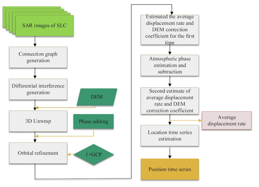
The obtained Sentinel-1A satellite data is processed by the SBAS-InSAR technology described above, and the key process of the data processing is shown in Figure 2.
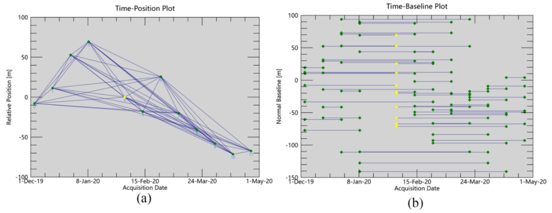
In order to generate as many interference pairs as possible and ensure the coherence of the interference pairs, the time threshold is set to 96 d and the space threshold is set to 100 m to generate 50 interference pairs considering the influence of the atmospheric phase (Figure 3). Specifically, differential interference processing is first conducted on the 50 interference pairs to unwrap. Then, stable control points are selected for orbit refining. Finally, the atmospheric phase error is removed, and the average displacement rate and time series displacement are calculated.

3.2.3. Result Analysis

After the Sentinel-1A satellite data is processed following the above procedure, a map of the LOS subsidence rate from 3 December 2019 to 25 April 2020 is obtained, shown in Figure 4. Then, according to the formula Δ h = Δ r / cos θ ( Δ r is the satellite LOS subsidence; θ is the angle of incidence, and Δ h is the vertical subsidence value), the subsidence rate in the direction of the radar line of sight is converted to the vertical direction.
It can be seen from Figure 4 that the largest subsidence occurred in the two areas A and B in the mining area with the maximum value of −274.012 mm/yr, and no serious subsidence existed in the rest of the mining area. After data investigation and field inspection, area A is a loose mound of the open-pit mining in another coal mine, and area B i.e., the study area in Figure 1, includes the 15209 mining face; the 15210 mining face; and the 14209 mining face (Figure 4). This paper focuses on the analysis of subsidence in area B.
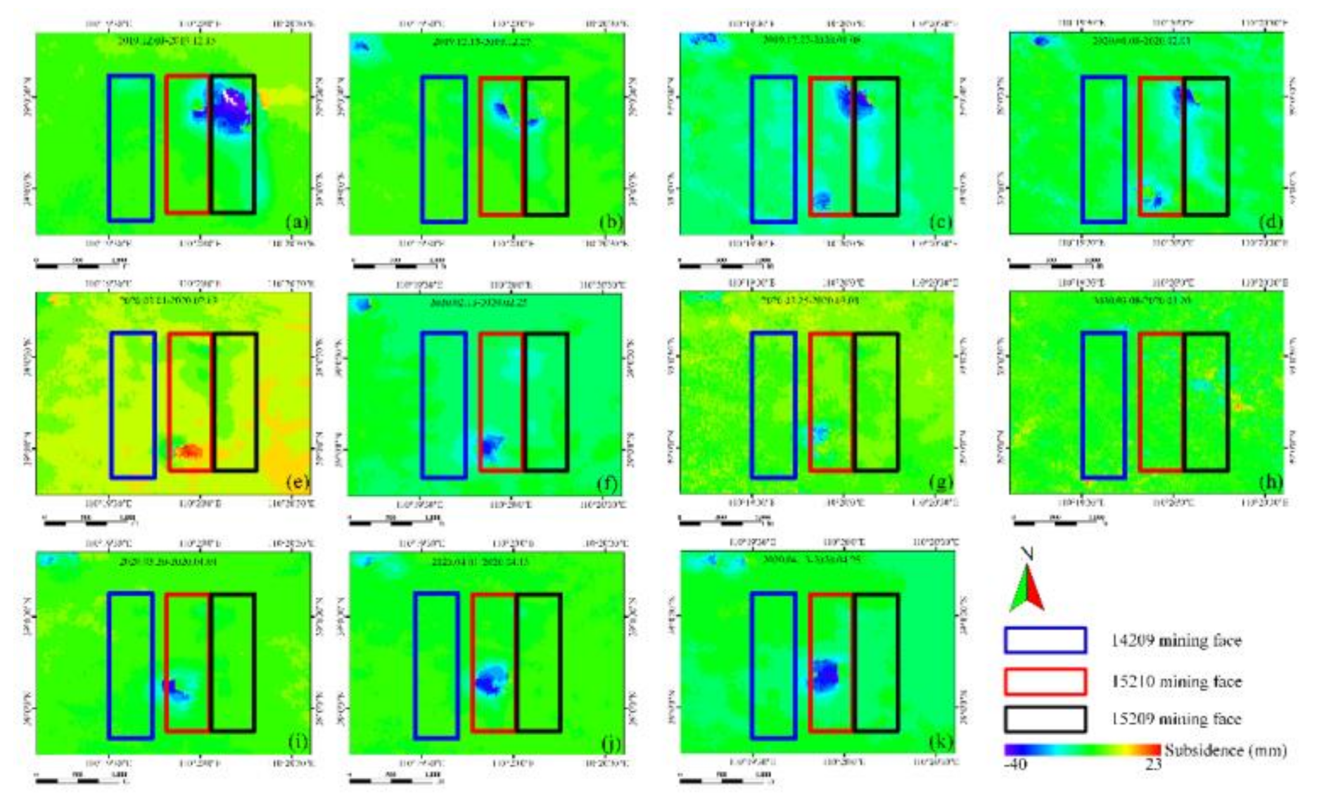
Figure 5 shows the respective deformations in 11 periods. Figures showed that in the periods the subsidence area of the study area were obvious. Combining the mining time and subsidence of each mining face, the subsidence is caused by the mining of the three mining faces 15209; 15210; and 14209, as shown in Figure 4.
Figure 6 shows the mining advances in the study area. In Figure 6, the yellow axis represents the mining time of each of the three mining faces, and the scale line represents the mining position of the mining face at this time. Comparing it with Figure 5, it can be found that in the same area the time of subsiding is consistent with the time of mining. The correlation between them implies that the surface subsidence is caused by the underground mining.
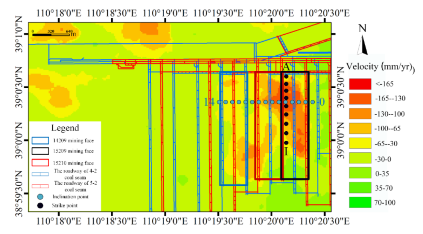
To further analyze the subsidence of the mining faces, the vertical subsidence amount of the mining faces and the influence range of the subsidence are analyzed quantitatively. The time-series subsidence amount of 15 observation points was extracted from the inclination in the subsidence area, and the observation points were numbered 0–14. Meanwhile, the time-series subsidence amount of nine observation points was extracted from the strike and numbered as A, B..., I. The survey line points and mining face positions are shown in Figure 7. In Figure 7, the thin blue line represents the roadway of 4−2 coal seam, the 14209 mining face located in the 4–2 coal seam. The thin red line represents the roadway of 5−2 coal seam, the 15209 mining face and 15210 mining face located in the 5−2 coal seam (coal seam is a bed of coal usually thick enough to be profitably mined).
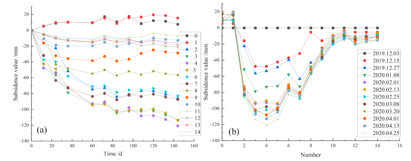
The subsidence amount at the inclination points and the accumulated subsidence amount at the inclination points are illustrated in Figure 8. It can be seen from Figure 8b that: (1) the subsidence amount of the 15209 mining face is the most obvious. The maximum subsidence amount increased to −120.759 mm; (2) the 15209 mining face and 15210 mining face each have subsidence basin; (3) the 15209 mining face started mining in May 2019 and the mining activity ended in December 2019. The 15209 mining face reached complete subsidence, so the center subsidence of the 15209 mining face is the most obvious, and it is funnel-shaped; (4) after March 2020, the subsidence of the 14209 mining face tends to 0, indicating that it has reached a stable state. The subsidence rate of mining face 15,209 is the largest from 27 December 2019 to 8 January 2020. Meanwhile, it can be analyzed from Figure 7 that: (1) no significant subsidence was observed at point 0 and point 1 from 3 December 2019 to 25 April 2020, indicating that the area of point 0 and point 1 is not affected by the subsidence of mining; (2) the 15209 mining face ended mining in December, and the subsidence increased slightly after March, which was basically stable; (3) the 14209 mining face ended mining in November, and the surface of the mining area was stable; (4) the 15210 mining face is being mined, so the subsidence is still increasing.
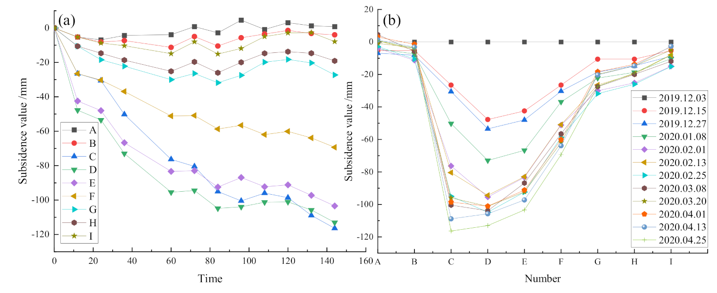
The subsidence results of the strike points are presented in Figure 9. It can be seen from Figure 5 and Figure 6 that the strike points are located at the 15209 mining face, and this mining face ended mining in December 2019. It can be seen from Figure 9 that the surface of the mining face still shows subsidence, and the subsidence presents a trend of decrease–increase–decrease, which is consistent with the subsidence caused by the longwall mining method. However, the subsidence amount near the point of the inclined edge of the mining face is basically between −10 mm and 10 mm, indicating that the surface is in a stable state with small surface shape variables and no obvious subsidence. In conjunction with Figure 8, the measurement error and mining boundary angle are considered, and taking the subsidence value of 10 mm as the critical value, the subsidence boundary can be obtained.

4. Slope Stability Analysis

4.1. Longwall Mining Boundary

The basic parameters of the mining face as Table 1 can be obtained from the relevant geological manual report. The subsidence coefficient, the horizontal movement coefficient, and the main influence angle tangent are the predicted parameters given in the research report of the first mining face. The subsidence of the 15209, 15210and 14209 mining faces is predicted respectively. The predicted boundary and the boundary obtained by SBAS-InSAR are shown as Figure 10. Based on the parameters provided, the predicted area should fully cover the actual subsidence area. According to the boundary shown in Figure 9, it can be found the existing subsidence method has a certain degree of accuracy in this area, but it cannot fully explain the subsidence range interpreted by SBAS-InSAR. In the O area in Figure 10, there is a certain difference in the inclination between the two boundaries, and the maximum difference between the two is 116 m.
Combined with the comprehensive analysis of the hydrology and geomorphology of the mining area and considering the characteristics of the surface damage proposed by Yi et al. [24] for coal mining in the loess plateau area, not only the surface damage characteristics of the coal mining under the loess layer but also the addition of surface movement and deformation under the conditions of the gully area need to be investigated. The slip caused by mining is closely related to the stability of the slope in the gully area. The prediction failure of area O may be due to the large slope and little vegetation in the mining area, resulting in poor slope stability. Therefore, if the coal seam is mined under the mining area, landslide and subsidence may occur, which leads to the expansion of the mining influence area.

4.2. Slope Stability Analysis

4.2.1. Slope Stability Evaluation

Landslides and subsidence problems in the slope of the mining area is studied. The slip caused by mining in the gully area is closely related to the stability of the slope in the gully area [25]. Chi Mu et al. have also confirmed that underground mining can cause landslides by analyzing the mechanism of landslide disaster [18]. In the loess gullies, the slope stability is usually evaluated with G in the following formula as an index of terrain mining conditions [18,26,27]
G = T S = h r sin 2 δ 2 C + h r cos 2 δ tan φ
In the formula, h is the thickness of the soil surface; r is the density of the soil; C is the cohesion in the soil; φ is the internal friction angle of the soil, and δ is the angle of the slope. The stability evaluation of the slope is based on the parameters listed in Table 3.
After consulting the data of the mining area, the relevant parameters of the mining area are listed in Table 4.
Based on Equation (6) and the slope parameters of the mining area and considering different slope angles, the results listed in Table 5 can be calculated.
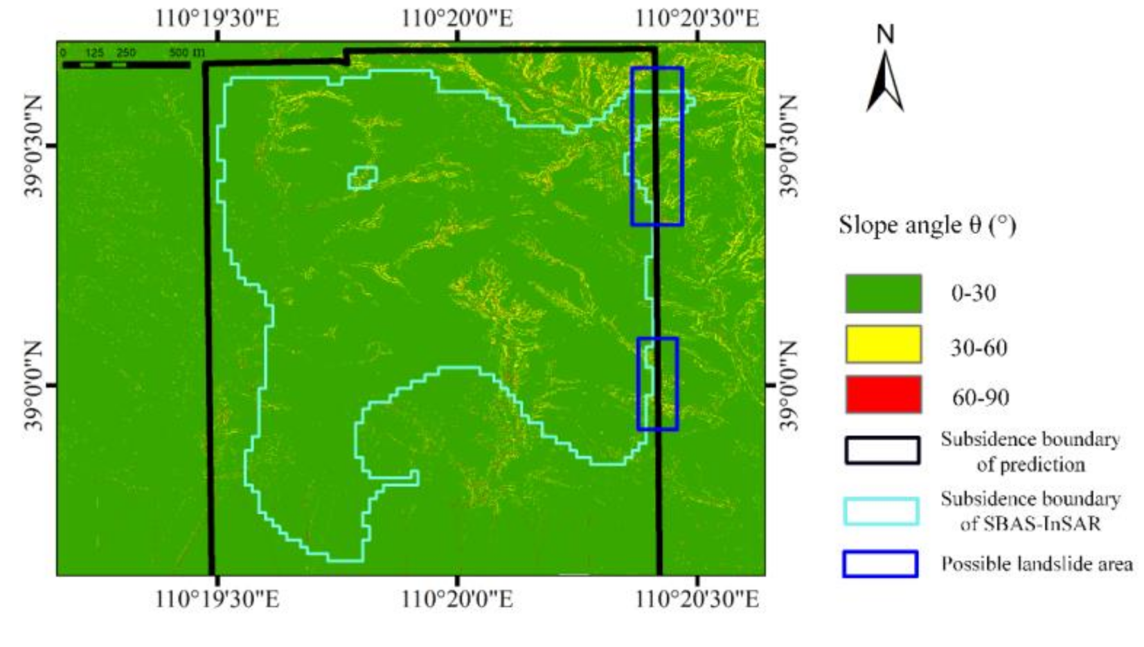
Then, considering the calculation error, the area with a slope of 30° or more is selected, which was located at the predicted boundary and close to the SBAS-InSAR boundary. According to the calculation result, the position where the slope angle of the boundary position is greater than 30° (the landslide is more likely to happen) is found and shown in Figure 11 (there are many slopes more than 30° in the area, but we focus on the analysis of the impact of landslide on the boundary, and do not discuss other positions). It can be seen from Figure 11 that the location of the landslide is highly consistent with the analysis results.

4.2.2. Force Analysis of Landslide

According to the Coulomb stress, the collapse of the soil is due to Coulomb stress failure, which is defined as [28,29]
CFS C 0 + μ σ + τ
C 0 here is the cohesion force of the material, μ is the friction coefficient, and σ and τ are the normal and shear stress on the interface, respectively. (For simplification the effect of fluid pressure is ignored). When subsidence takes place due to mining, the shear stress is increased due to differential motion of the material at some weak zones, resulting in the Coulomb stress reaching its failure threshold CFS , causing fissures/cracks to appear in the media (Figure 12). This process reduces the cohesion force C 0 to zero at the crack surface, which further accelerates the deformation. Eventually some chucks of the material located at the edge of high slope region will slide under gravity. Due to the loss of cohesion at the boundary cracks adhering them to the stable part of the terrane, which makes the slope slides downward and causes landslide.

4.2.3. Process of Landslide

The process of landslide formation in mining area is as follows: (1) Along with coal mining (Figure 12), goafs were formed in the mining face. The goaf subsidence due to the action of gravity, the Coulomb stress reaching its failure threshold CFS . As shown the ground fissure in the Figure 12, the ground fissure is the most direct manifestation. (2) The scope of goaf gradually expands, and the vertical subsidence spreads to the slope surface. (3) The upper part of the slope was affected by the goaf and gravity, and a number of thin cracks appeared, which affect the stability of the upslope. (4) Due to the loss of cohesion at the boundary cracks adhering them to the stable part of the terrain, the instability of the upper slope body is transmitted to the lower slope body, and develops to the bottom, landslides occur under the action of external conditions such as rain or gravity.

4.3. Discussion

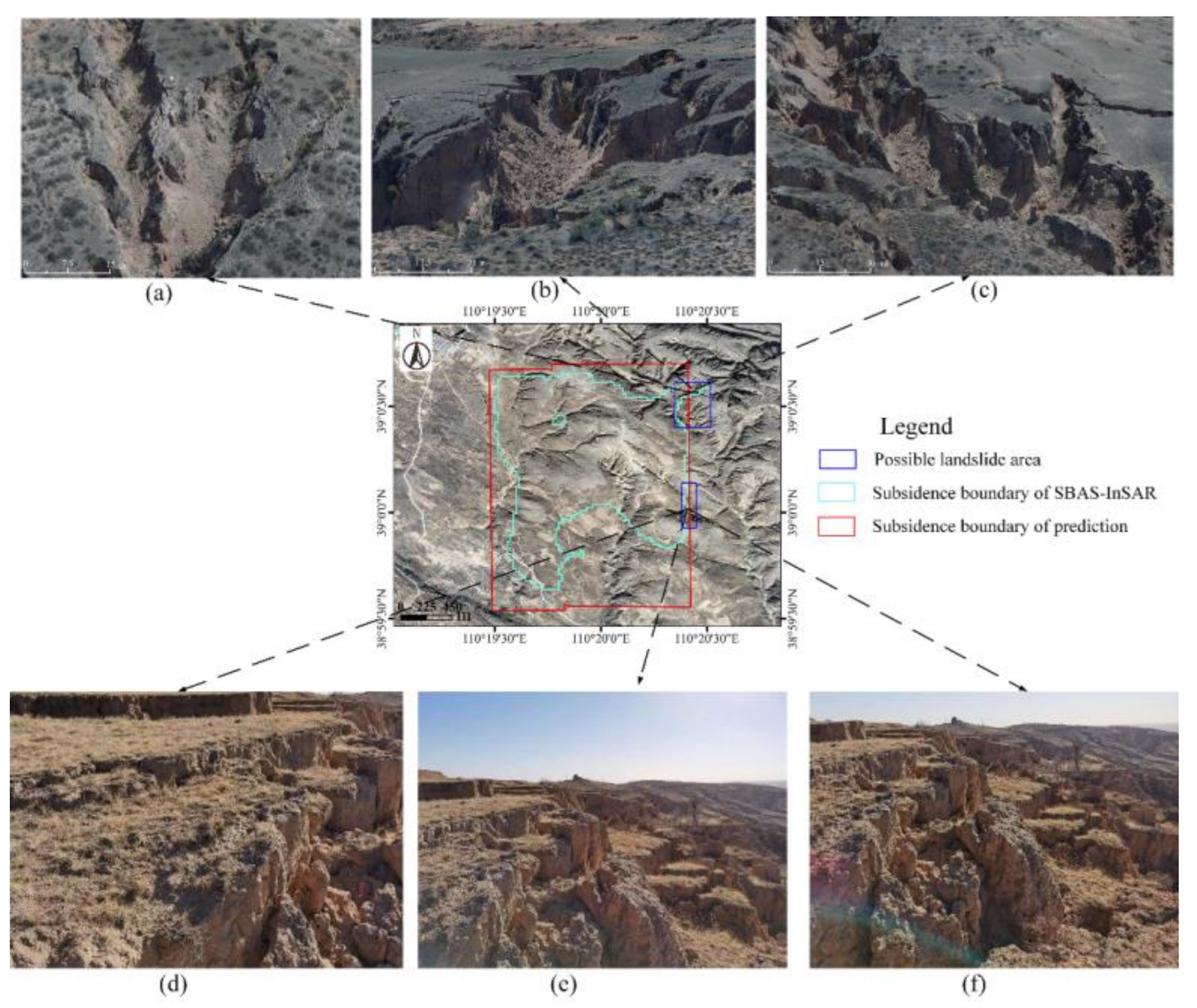
As mining progresses, goaf is formed in the mining face. The rock and soil sink due to gravity. The subsidence of overlying strata will cause ground fissures. On slopes, due to the tensile force of the ground fissures, the ground fissures extend downwards. Through our analysis, the slope is unstable when the angle of the slope is large. Combining the force analysis of the landslide and the formation process of the landslide, it can be analyzed the landslides would occur in this area due to the tensile force of ground fissures caused by mining and other external factors. To verify the reliability of the analysis results, several on-site investigations are performed on the mining-affected areas of three mining faces. Slope slippage happened in the two possible slippage areas in Figure 11, which is consistent with the expected result (Figure 13a–f).
It is evident that the slippage of the slope expanded the subsidence range, so that the subsidence boundary measured by SBAS-InSAR is beyond the predicted boundary. At the boundary of mining impact, due to landslides, the mining impact range will spread beyond the predicted boundary as the Figure 11. It also shows that the use of the predicted boundary combined with slope stability analysis can effectively identify the slope slippage at the subsidence boundary.

5. Conclusions

In this paper, we obtained the time series information of land subsidence from December 2019 to April 2020 for the mining area based on the SBAS-InSAR technology, and characteristic points are extracted from the strike and inclination of coal seam to analysis the subsidence. The analysis results of the feature points show that: mining at the two mining faces of 15209 and 15210 causes obvious funnel-shaped subsidence. The 14209 mining face was basically stable four months later after the end of mining at the mining face. The peak period of the 15209 mining face subsidence is 36 days after the mining of this mining face. In addition, the actual subsidence range of the mining area is obtained by using the SBAS-InSAR technology.
On the other hand, the subsidence prediction, SBAS-InSAR and slope stability are combined to analysis the influence of landslides on the subsidence range. This study confirmed that the impact of mining activity could be transmitted beyond the impact boundary determined by predicted subsidence models. When the slope angle is large, mining causes ground fissures and slope instability, and the ground fissures conduct downwards. Under the external condition such as rain erosion and the gravity, the landslide resistance coefficient of the surface decreased, resulting in a landslide. The landslide at the subsidence boundary can be effectively identified by combining the slope stability analysis method and the predicted boundary. In addition, early detection of subsidence boundary landslides can be carried out by topographic survey work.
This study provides important guidance for subsequent environmental protection and management of mining areas. This work helps provides a practical method to predict the subsidence boundary and potential boundary landslide.

Author Contributions

Conceptualization, M.Y. and M.L.; Methodology, M.Y.; Software, M.Y., M.L., B.L. and H.L.; Validation, M.Y. and H.L.; Formal analysis, M.Y.; Investigation, M.Y.; Resources, M.L. and W.Z.; Data curation, M.L.; Writing—original draft preparation, M.Y.; Writing—review and editing, M.L., H.L. and P.L.; Visualization, M.Y. and H.L.; Supervision, P.L.; Project administration, M.L.; Funding acquisition, M.L. All authors have read and agreed to the published version of the manuscript.

Funding

This research was funded by the Natural Science Foundation of China (grant no. 51774281).

Institutional Review Board Statement

Not applicable.

Informed Consent Statement

Not applicable.

Data Availability Statement

Not applicable.

Acknowledgments

The authors are grateful to the editor and anonymous reviewers for their valuable suggestions which greatly help to improve the original manuscript.

Conflicts of Interest

The authors declare no conflict of interest.

References

  1. Chen, P. Study on integrated classification system for Chinese coal. Fuel Process. Technol. 2000, 62, 77–87. [Google Scholar] [CrossRef]
  2. Zhao, B.; Tong, C.; Liu, Z. Characteristics of mining-induced sur-face damage in western ecological fragile region. J. Cent. South. Univ. 2017, 48, 2991–2998. [Google Scholar]
  3. Tang, F.; Dong, L.; Wang, Z. InSAR three-dimensional displacement inversion model of near-horizontal coal seam mining based on subsidence sym-metry characteristics. J. China Coal Soc. 2019, 44, 210–220. [Google Scholar]
  4. Liang, T. Monitoring the surface deformation of mining area by using short baseset InSAR technique. Bull. Surv. Mapp. 2014, S1, 82–84. [Google Scholar]
  5. Chai, H.; Hu, J.; Geng, S. SBAS-InSAR Monitoring Method of ground sub-sidence in mining areas by fusion with measured Data. J. China Coal Soc. [CrossRef]
  6. Zhu, J.; Yang, Z.; Li, Z. Recent progress in retrieving and predicting mining-induced 3D displace-ments using InSAR. Acta Geod. Cartogr. Sin. 2019, 48, 135–144. [Google Scholar] [CrossRef] [Green Version]
  7. Ferretti, A.; Novali, F.; Bürgmann, R.; Hilley, G.; Prati, C. InSAR permanent scatterer analysis reveals ups and downs in San Francisco Bay Area. Eos Trans. Am. Geophys. Union 2004, 85, 317. [Google Scholar] [CrossRef]
  8. Zhu, J.-J.; Xing, X.-M.; Hu, J.; Li, Z.-W. Monitoring of ground surface deformation in mining area with InSAR technique. Chin. J. Nonferr. Met. 2011, 21, 2564–2576. [Google Scholar]
  9. Fan, H. Study on Several Key Algorithms of Insar Technique and Its Application in Land Subsidence Monitoring; China University of Mining and Technology: Xuzhou, China, 2010. [Google Scholar]
  10. Lanari, R.; Mora, O.; Manunta, M.; Mallorqui, J.J.; Berardino, P.; Sansosti, E. A small-baseline approach for investigating deformations on full-resolution differential SAR interferograms. IEEE Trans. Geosci. Remote. Sens. 2004, 42, 1377–1386. [Google Scholar] [CrossRef]
  11. Tian, Y.; Lei, S.; Bian, Z. Monitoring and forecasting on inner dump subsidence based on SBAS and chaotic theory. J. China Coal Soc. 2019, 44, 3865–3873. [Google Scholar] [CrossRef]
  12. Diao, X.; Bai, Z.; Wu, K.; Zhou, D.; Li, Z. Assessment of mining-induced damage to structures using InSAR time series analysis: A case study of Jiulong Mine, China. Environ. Earth Sci. 2018, 77, 1–14. [Google Scholar] [CrossRef]
  13. Li, J.; Gao, F.; Lu, J. An application of InSAR time-series analysis for the assessment of mining-induced structural damage in Panji Mine, China. Nat. Hazards 2019, 97, 243–258. [Google Scholar] [CrossRef]
  14. Liu, L.; Yu, J.; Chen, B.; Wang, Y. Urban subsidence monitoring by SBAS-InSAR technique with multi-platform SAR images: A case study of Beijing Plain, China. Eur. J. Remote Sens. 2020, 53, 141–153. [Google Scholar] [CrossRef] [Green Version]
  15. Li, D.; Deng, K.; Gao, X.; Haipeng, N. Monitoring and analysis of ground subsidence in mining areas based on SBAS-InSAR. J. Wuhan Univ. Inf. Sci. Ed. 2018, 43, 1531–1537. [Google Scholar]
  16. Casu, F.; Manzo, M.; Lanari, R. A quantitative assessment of the SBAS algorithm performance for surface deformation retrieval from DInSAR data. Remote Sens. Environ. 2006, 102, 195–210. [Google Scholar] [CrossRef]
  17. Yang, J.; Wu, K.; Diao, X. Application of SBAS-InSAR Deformation Characteristic Monitoring in Cause Analysis of Building Damage. Saf. Coal Mines 2020, 51, 174–178, 183. [Google Scholar]
  18. Mu, C.; Yu, X.; Zhao, B.; Zhang, D.; Mao, X.; Zhu, J. The Formation Mechanism of Surface Landslide Disasters in the Mining Area under Different Slope Angles. Adv. Civil Eng. 2021, 2021, 1–13. [Google Scholar] [CrossRef]
  19. Lian, X.; Li, Z.; Yuan, H.; Hu, H.; Cai, Y.; Liu, X. Determination of the Stability of High-Steep Slopes by Global Navigation Satellite System (GNSS) Real-Time Monitoring in Long Wall Mining. Appl. Sci. 2020, 10, 1952. [Google Scholar] [CrossRef] [Green Version]
  20. Salmi, E.F.; Nazem, M.; Karakus, M. The effect of rock mass gradual deterioration on the mechanism of post-mining subsidence over shallow abandoned coal mines. Int. J. Rock Mech. Min. Sci. 2017, 91, 59–71. [Google Scholar] [CrossRef]
  21. Berardino, P.; Fornaro, G.; Lanari, R.; Sansosti, E. A new algorithm for surface deformation monitoring based on small baseline differential SAR interferograms. IEEE Trans. Geosci. Remote Sens. 2002, 40, 2375–2383. [Google Scholar] [CrossRef] [Green Version]
  22. Zhou, L.; Guo, J.; Hu, J.; Li, J.; Xu, Y.; Pan, Y.; Shi, M. Wuhan Surface Subsidence Analysis in 2015–2016 Based on Sentinel-1A Data by SBAS-InSAR. Remote Sens. 2017, 9, 982. [Google Scholar] [CrossRef] [Green Version]
  23. Dong, S.; Chong, Y.; Hu, H. Ground subsidence monitoring during 2015-2018 in China Changzhou based on time series InSAR method. J. Nanjing Univ. 2019, 55, 370–380. [Google Scholar]
  24. Luo, Y. Us Longwall Mining and Subsidence REsearch. West. Va. Univ. 2011, 6, 106–125. [Google Scholar]
  25. He, S. Analysis of Influencing Factors of Slope Stability Based on Loess Gully Region. Coal Technol. 2019, 38, 48–51. [Google Scholar] [CrossRef]
  26. Zhu, H.; Zhang, L.M.; Xiao, T.; Li, X.Y. Enhancement of slope stability by vegetation considering uncertainties in root distribution. Comput. Geotech. 2017, 85, 84–89. [Google Scholar] [CrossRef]
  27. Stead, D. The Influence of Shales on Slope Instability. Rock Mech. Rock 2015, 49, 635–651. [Google Scholar] [CrossRef]
  28. Cocco, M.; Rice, J.R. Pore pressure and poroelasticity effects in Coulomb stress analysis of earthquake interactions. J. Geophys. Res.-Solid Earth 2002, 107, 17. [Google Scholar] [CrossRef]
  29. Shi, Y.L.; Yin, D.; Ren, T.X. The variation of coseismic static stress deviation consistent with theoretical prediction was observed for first time-Observation of borehole strain of the Yuanping ML 4.7 earthquake in Shanxi on 7 April 2016. Chin. J. Geophys. 2021, 64, 1937–1948. [Google Scholar] [CrossRef]
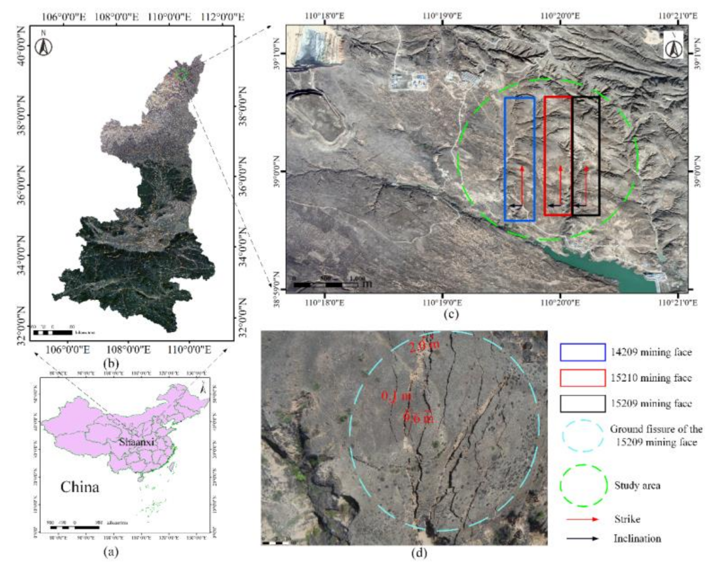
Figure 1. Location and current status of the study area: (a) China; (b) Shaanxi province; (c) The green ellipse is the study area, which includes 14209 mining face, 15209 mining face and 15210 mining face; (d) Ground fissure of 15209 mining face. (The base map of (b,c) is Google Earth; (d) is a UAV aerial photo).
Remotesensing 13 03107 g001
Figure 2. SBAS-InSAR processing flow chart.
Remotesensing 13 03107 g002
Figure 3. Spatial and temporal baselines utilized in the current study: (a) time-position plot of synthetic aperture radar (SAR) image acquisitions; (b) time-baseline plot of interferometric pairs of SAR images.
Remotesensing 13 03107 g003
Figure 4. Subsidence rate diagram of the study area based on SBAS-InSAR technology (a negative value means a subsidence and a positive value means an uplift): (1) area A is a loose mound of the open-pit mining in another coal mine. (2) area B is the study area.
Remotesensing 13 03107 g004
Figure 5. Subsidence of the study area based on SBAS-InSAR technology by period (A negative value represents a subsidence and a positive value means an uplift) (ak).
Remotesensing 13 03107 g005
Figure 6. Mining time of three mining faces (the yellow axis represents the mining time).
Remotesensing 13 03107 g006
Figure 7. Location of the survey line points.
Remotesensing 13 03107 g007
Figure 8. Subsidence of the inclination points: (a) Subsidence of the points with time. (b) Cumulative subsidence at each time.
Remotesensing 13 03107 g008
Figure 9. Subsidence of the strike points: (a) Subsidence of the points with time. (b) Cumulative subsidence at each time.
Remotesensing 13 03107 g009
Figure 10. Subsidence boundary by SBAS-InSAR and the subsidence boundary by prediction (the green circle represents the area where InSAR boundary is beyond the prediction boundary).
Remotesensing 13 03107 g010
Figure 11. Slope angle of the study area.
Remotesensing 13 03107 g011
Figure 12. Goaf area and diagram of surface soil stress direction.
Remotesensing 13 03107 g012
Figure 13. Field investigation of landslide: (ac) Landslide of the O area. (df) Another landslide area.
Remotesensing 13 03107 g013
Table 1. Basic parameters of the mining faces.
The Mining Face Strike   Length   L 0
(m)
Inclination   Length   L 1
(m)
Coal   Seam   Dip   α
(°)
Mining   Depth   H 0
(m)
Coal Seam Thickness
(m)
15209 mining face18603001–3160–2406.1
15210 mining face18602951–3160–2405.9
14209 mining face1915300054–1203.6
Table 2. Sentinel-1A data parameters.
TimeImaging ModeNumberBandPolarization ModeOrbital Direction
3 December 2019–25 April 2020IW12CVV + VHAscending
Table 3. Slope stability classification and landslide probability classification.
G -Value StabilityPossibility of Landslide
G < 0.83goodless
0.83 ≤ G < 1generalpossible
G ≥ 1poormore
Table 4. Slope related parameters.
Soil   Surface   Thickness   h   ( m ) Soil   Density   r (kg/m3) Internal   Friction   Angle   φ (°) Soil   Cohesion   C (Pascal)
701800318000
Table 5. Evaluation of different slope angles.
NumberSlope Angle (°) G -Value Slope StabilityPossibility of Landslide
150.013goodlow
2100.265goodlow
3200.541goodlow
4250.688goodlow
5300.842generalpossible
6401.183poorhigh
7501.579poorhigh
8702.402poorhigh
9802.095poorhigh
Publisher’s Note: MDPI stays neutral with regard to jurisdictional claims in published maps and institutional affiliations.