Abstract
Millimeter-wave (MMW) 3-D imaging technology is becoming a research hotspot in the field of safety inspection, intelligent driving, etc., due to its all-day, all-weather, high-resolution and non-destruction feature. Unfortunately, due to the lack of a complete 3-D MMW radar dataset, many urgent theories and algorithms (e.g., imaging, detection, classification, clustering, filtering, and others) cannot be fully verified. To solve this problem, this paper develops an MMW 3-D imaging system and releases a high-resolution 3-D MMW radar dataset for imaging and evaluation, named as 3DRIED. The dataset contains two different types of data patterns, which are the raw echo data and the imaging results, respectively, wherein 81 high-quality raw echo data are presented mainly for near-field safety inspection. These targets cover dangerous metal objects such as knives and guns. Free environments and concealed environments are considered in experiments. Visualization results are presented with corresponding 2-D and 3-D images; the pixels of the 3-D images are . In particular, the presented 3DRIED is generated by the W-band MMW radar with a center frequency of , and the theoretical 3-D resolution reaches 2.8 mm × 2.8 mm × 3.75 cm. Notably, 3DRIED has 5 advantages: (1) 3-D raw data and imaging results; (2) high-resolution; (3) different targets; (4) applicability for evaluation and analysis of different post processing. Moreover, the numerical evaluation of high-resolution images with different types of 3-D imaging algorithms, such as range migration algorithm (RMA), compressed sensing algorithm (CSA) and deep neural networks, can be used as baselines. Experimental results reveal that the dataset can be utilized to verify and evaluate the aforementioned algorithms, demonstrating the benefits of the proposed dataset.
1. Introduction
Millimeter-wave (MMW) 3-D imaging technology [1,2,3,4] has attracted enormous attention because non-hazardous radiation of MMW and the work pattern all-day, all-weather. Furthermore, the MMW radar shows superiority in safety inspection [5,6], subsurface detection [7,8], medical monitoring [9,10,11], intelligent driving [12,13], and nondestructive testing [14]. Besides, the advantages of the MMW radar device are the smaller component size, higher integration level, and wider frequency spectrum, helping us to achieve high-resolution near-field 3-D imaging. However, compared to optical images, the MMW radar requires a large aperture to obtain high-resolution imaging results. Although the hardware is constantly being upgraded, there is still a huge challenge for obtaining raw echo data with millimeter resolution. An effective way is by adopting the theory of the synthetic aperture radar (SAR) to reduce hardware cost and complexity. Since the concept of SAR was first proposed in 1951 [15], the technology has developed rapidly over the next 70 years. The planar scanning pattern is used to obtain a large virtual aperture. Using SAR theory, the original resolution limit is broken, and higher resolution imaging data can be obtained. In [16], the development of SAR MMW imaging testbeds has been realized, and low-cost equipment has been adopted.
In the aspect of imaging, all kinds of excellent algorithms are proposed. Back projection algorithm (BPA) [17,18,19] is the classical algorithm in the radar field. BPA traverses all the points in the imaging space and compensates the residual phase to obtain the reconstructed results and can provide a feasible implementation for an arbitrary radar array arrangement. However, when the number of array elements is large, the computing efficiency will be lost. Therefore, the range migration algorithm (RMA) [20,21], which is a more efficient algorithm, has emerged. RMA uses fast Fourier transform (FFT) and matrix multiplication in the frequency domain to complete imaging. However, the traditional algorithms are constrained by the Nyquist sampling criterion. An ideal imaging platform implementing high-resolution under the Nyquist sampling criterion always needs an extremely large number of array elements, leading to difficulty with data processing. The compressed sensing algorithm (CSA) [22,23,24] is an emerging technology in recent years. It has shown great advantages in many fields [25,26,27] because of its characteristic of breaking through the limitation of the Nyquist sampling criterion and using a low sampling rate to achieve high-resolution imaging results. However, the negative effect of CSA is the increase of computation by transforming the radar imaging problem into an optimization problem. Furthermore, the method of using machine learning to build deep neural networks for imaging is also emerging, and many efficient technologies have come out, such as ISTA-Net [28], AMP-Net [29]; however, they are not used for MMW imaging. In the near-field MMW imaging field, Wang et al. presented a novel 3-D microwave sparse reconstruction method based on a complex-valued sparse reconstruction network (CSR-Net) [30], a novel range migration kernel-based iterative-shrinkage thresholding network (RMIST-Net) [31], and a lightweight FISTA-Inspired Sparse Reconstruction Network for MMW 3-D Holography [32]. In the aspect of application, a detection and classification algorithm based on the MMW radar and camera fusion is proposed in [33]; Cui et al. [34] presented a K-means-based machine learning algorithm for user clustering with MMW system; Ref. [35] demonstrates that MMW can be used for robust gesture recognition and can track gestures; A unified framework of multiple target detection, recognition, and fusion is proposed in [36]. Furthermore, Zhao et al. [37] published an improved wiener filter super-resolution algorithm for MMW imaging. Moreover, Ref. [38] proposed a 3-D reconstruction method of array InSAR based on Gaussian mixture model clustering. Finally, Shi et al. introduced near-field MMW 3-D imaging and object detection method [39].
Unfortunately, many urgent theories and algorithms in this research field cannot be fully verified by simulation experiments. In [40], a MMW dataset, ColoRadar, is provided in the field of robotics. The data in ColoRadar are from radar sensors as well as 3-D lidar, IMU, and highly accurate groundtruth. It is not a strict MMW radar dataset. To address this issue, in this paper, a high-resolution MMW 3-D radar dataset for imaging and evaluation is proposed, dubbed as 3DRIED.
To first build a complete dataset, different environments are selected to acquire raw echo data, and different algorithms are selected to process raw data. There is a total of 81 radar echo data and corresponding high-resolution imaging results in 3DRIED. The targets include knives, guns, and other dangerous materials. At the same time, the targets under concealed conditions are also considered. The advantages of 3DRIED are that target types are complete and scene conditions are diverse. It can play a role in safety inspection or help others to verify their algorithms but also can be a trained deep network or used in detection and recognition of 3-D targets. The method of combining the SAR system and broadband MMW is applied to build the experimental platform. BPA, RMA, CSA, and RMIST-Net are selected to imaging and evaluate the dataset. There are equivalent array elements in the array plane and raw echo data with a size of , which are the basis for doing high-resolution imaging. First, we provide unprocessed ADC samples from each radar measurement. Second, we provide 2-D and 3-D imaging results for each radar data using different algorithms. Lastly, we provide the optical images and numerical evaluation.
We hope that our dataset can make some contributions to the research field. The proposed dataset will be available at https://github.com/zzzc1n/3-D-HPRID.git (accessed on 22 July 2021). In future work, It will also expand its content to consider more complex environments and scattering targets with different characteristics. A concise summary of the contributions are as follows:
- 1.
- Sharing the same principle with SAR, an experimental system with MMW radar is constructed, which works in the mono-static scanning mode.
- 2.
- 3DRIED contains 9 types of targets, with a total of 81 near-field radar data. Target types are complete; environments conditions are diverse; and applications are extensive.
- 3.
- The proposed dataset is used to evaluate several widely used MMW imaging algorithms to obtain 2-D and 3-D imaging results, and different numerical evaluation indexes are given as a baseline.
The paper consists of 4 parts. Section 2 is the 3-D near-field radar imaging model, the construction of the experimental platform of the near-field MMW radar, and the imaging algorithms for subsequent data visualization. Section 3 demonstrates the system of data acquisition and the proposed dataset. The analysis and discussion of 3DRIED are also shown in this section. Furthermore, the last section will summarize this paper.
2. Related Theory
The construction of 3DRIED consists of two parts: data acquisition and processing. The total framework is shown in Figure 1, and the following parts will be developed following this structure.
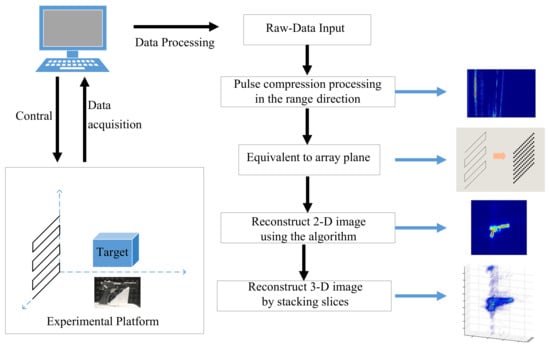
Figure 1.
The framework of 3-D MMW data acquisition and processing.
2.1. Signal Model
As shown in Figure 2, the 3-D near-field radar imaging model is presented, where y represents the range direction, and x and z represent the horizontal and vertical directions, respectively. The array elements represent the virtual antenna phase center , which is dependent on the position of receivers and transmitters. The target coordinates are represented as . Therefore, in this model, the distance history of the target can be described as Equation (1),
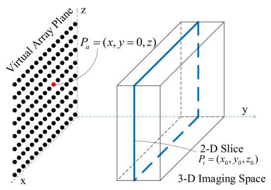
Figure 2.
3-D near-field radar imaging model.
In the array plane, the element spacing determines the grating lobe range of imaging, and the whole array element size determines the imaging resolution in the plane. Three-dimensional imaging space is divided into a series of 2-D slices. The radar system can obtain a large distance range and high resolution when transmitting the frequency-modulated continuous-wave (FMCW) signal.
FMCW refers to a wave whose frequency increases linearly with time, as shown in Figure 3. FMCW can have a large bandwidth, bring high range resolution, but also make velocity estimation and angle estimation easy; FMCW has a great advantage in the MMW radar high-resolution imaging. The FMCW signal form is Equation (2).
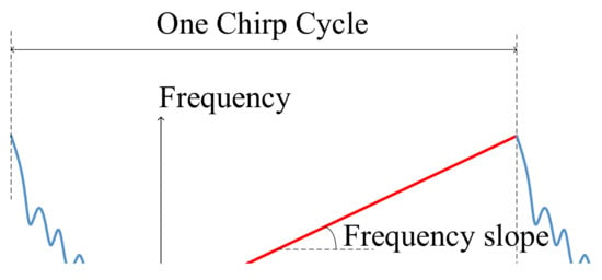
Figure 3.
3-D near-field signal waveform.
We can get the initial echo signal as Equation (3) in the receiver ports, which is the beat signal
where represents the scattering coefficient of point , and represents the echo delay from the scattering point to the equivalent array element. In this expression, the first exponential term contains the information of the scattering target in the dimension of the virtual array plane and the second exponential term contains the information of the range direction.
The echo data after range compression is corrected by distance migration, and the coupling relationship of the echo data between the array plane and the distance direction is released. For near-field scenes at close range, the amount of range migration is usually less than a resolution unit. The process of migration correction can be omitted, so the echo data between different distances are independent of each other. The form of echo data after pulse compression can be expressed as follows:
where , is the radar range ambiguity function, is the wave number of signal carrier frequency, and is the signal wavelength. For 3-D imaging space, the overall echo data is the integral or accumulation of each scattering element in the imaging space. The echo data for the three following algorithms are all based on Equation (5).
and are the sampling points in x and z directions, and y represents the range.
Moreover, the 3-D near-field radar imaging system combining MIMO array and the broadband signal can significantly reduce the number of transmitters and receivers to lower the cost of system hardware, which has the advantages of low hardware complexity and high efficiency. The system model is shown in Figure 2.
The millimeter sensor scans a 2-D array plane based on the scanning trajectory, then it can be equivalent to a virtual synthetic aperture whose size is related to the motion path; thus, a large irradiation range and high resolution are obtained. To avoid an aliasing effect and sidelobe clutter, achieve the imaging results with a high Signal-to-Noise Ratio (SNR) and good dynamic range. The transceiver spacing for the MIMO antenna array is necessary [6,41]. For our 3-D near-field radar imaging system, the cross-range resolutions along with horizontal and vertical directions [6] can be expressed as:
where is the wavelength of center frequency, and are the aperture width of transmitting and receiving array on the x-axis, and are the aperture width of transmitting and receiving array on the z-axis, which are both D in this experiment. Then the cross-range resolutions along horizontal and vertical directions can be simplified to Equation (8),
If the distance between two objects is too close, the two received signals after the Fourier transform will overlap in the frequency domain, and the two peaks cannot be shown. That is, distances are blurred, and two targets will be considered one target. The minimum distance is range resolution. Assuming that the minimum distance between the two objects is if they are distinguishable, the must satisfy:
Therefore, the range resolution can be obtained, as shown in Equation (10).
2.2. 3-D Imaging Algorithm
The algorithms used in this paper are: back projection algorithm (BPA), range migration algorithm (RMA), compressed sensing algorithm (CSA), and RMIST-Net. BPA and RMA are based on the matched filtering theory for imaging. CSA processes the radar echo data using the compressed sensing theory. RMIST-Net combines the advantages of the matched filtering and compressed sensing theory, obtains the imaging results through the deep neural networks, and improves the imaging accuracy and computing efficiency.
2.2.1. Range Migration Algorithm
The echo data at the transceivers is
Using RMA to process the echo data in near-field conditions is different from in far-field, Equation (11) represents a spherical wave, which can be decomposed into an infinite superposition of plane waves by Equation (12) [42]
, , are the components of spatial wave number k in directions, respectively, and they satisfy the relationship in Equations (13) and (14).
Through the decomposition into plane waves
where the inner double integral in Equation (15) represents the 2-D Fourier transform of the reflectivity function, expressed as , the outer double integral in Equation (15) represents the 2-D inverse Fourier transform of the reflectivity function, expressed as ,
Therefore, the 2-D RMA image at a distance of R from the sensor can be constructed as Equation (17).
The 3-D RMA images can be obtained by superimposing a series of 2-D slices in the range direction. Under the conditions of under-sampling or an uneven array, BPA can be considered due to the strong adaptability to various radar methods and excellent focusing effect. The formula will not be introduced here.
2.2.2. Compressed Sensing Algorithm
The CS signal processing theory generally has three parts: the sparse representation, the measurement matrix, and the sparse reconstruction algorithm. For 3-D imaging, due to the existence of a large number of non-target regions, such as the atmosphere region and the electromagnetic shielding region, the scattering target only occupies a part of the whole 3-D imaging space, then the target that is sparsely distributed can be considered; of course, this does not include the concealed targets in later sections, as they are weakly sparse or non-sparse. In this article, we used the 3-D SAR sparse imaging method: Sparsity Bayesian Recovery via Iterative Minimum (SBRIM) [43], as shown in Algorithm 1. The measurement matrix on each plane can be expressed as a matrix compensating the time delay phase according to Equation (4).
In the CS signal processing theory, radar echo data can be expressed as:
where is the measurement matrix, is noise, and is the scattering property of radar scanning target. Assuming that the posterior probability of echo data obeys the Gaussian distribution, the prior probability of scattering property obeys Equation (19), and the prior probability of noise obeys . The presetting parameter , .
According to the Bayesian criterion, the posterior probability of scattering property can be obtained as follows:
Using the maximum likelihood (ML) estimation criterion, the scattering property can be estimated by using Equation (21). CSA transforms the 3-D radar imaging problem into the optimization problem in the complex domain and completes 3-D radar imaging.
| Algorithm 1: Compressed Sensing Algorithm (CSA) |
| Given: Raw echo , measurement matrix ; Output: 3-D imaging result cube Initialize: Parameters , p,and , iterative threshold ; 1: , , set ; 2: 3: Diagonal matrix : ; 4: ; 5: ; 6: ; 7: 8: = . |
2.2.3. Rmist-Net
RMIST-Net [31] generates imaging results through multiple iterations based on the theory of matched filtering and compressed sensing. Detailed steps can be found in [31] but will not be detailed here. The echo data can be expressed as Equation (18). The deep neural network constructed by RMIST-Net is shown in Figure 4, which iterates the steps
where , is a stepsize, is the residual measurement error, is the sparse representation function, is the soft-thresholding shrinkage function, expressed as Equation (24).

Figure 4.
The feed-forward neural network constructed by unfolding iterations of RMIST-Net.
3. Dataset
3.1. The System of Date Acquisition
In this part, we will introduce parameter settings of the experiment platform and the imaging results of actual measured data using RMA. The effectiveness and completeness of our 3-D near-field radar imaging system are evaluated.
3.1.1. Experimental Equipment
As shown in Figure 5, the system devices include a two-axis controllable stepper, ‘IWR 1443’ MMW radar sensor, ‘DCA 1000’ data acquisition card, personal computer (PC), and the targets.
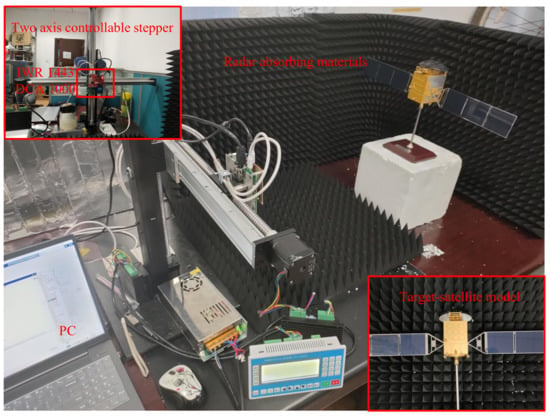
Figure 5.
The experimental equipment of data acquisition system.
PC is connected to the radar sensor and the data acquisition card, and ‘mmWave-studio’ software is used to control the transmitting FMCW signal on the radar sensor. The raw radar echo data are transmitted back to the PC through the network port after they are collected by the data acquisition card and stored as a binary file for subsequent data processing. The scanning trajectory of the radar sensor is controlled by the two-axis controllable stepper to complete the whole planar scanning process. Because the dielectric properties of polystyrene foam are close to those of space and the interference to the actual target is small, some foam blocks are used to fix the target in the experiment. MMW sensor ‘IWR1443’ manufactured by Texas Instruments (TI) can achieve 77–81 FMCW [44], and the wavelength is approximately. It achieves a high degree of integration. ‘IWR1443’ includes three transmitting antennas and four receiving antennas (3T4R), which can achieve a Multiple Input Multiple Output (MIMO) pattern. The ‘DCA1000’ module provides data capture and transmission for signals from TI IWR radar sensors. In the process of data collection, the sensor using pattern 1T4R transmits the FMCW signal in the W-band, and the frequency is in 77–81. The frequency K is 70.295 MHz/s, the number of ADC samples is 256, the sampling rate is 5000 ksps, the signal period is 50 ms, the number of pulses per second is 20. The scanning trajectory of the sensor forms an array plane, horizontal sampling interval [45] is , the vertical sampling interval is , and the size of the synthetic aperture is 0.4 m × 0.4 m. In the array plane, we can get equivalent array elements, and the size of raw echo data is , where ‘4’ means that four receiving antennas are working simultaneously in this MMW radar sensor.
3.1.2. Experimental Results
A 1:35 satellite model is used to verify the effectiveness and completeness of the 3-D near-field MMW radar imaging system. Figure 5 is the experimental scene. In order to achieve a quantitative analysis, the image entropy and contrast [46] are introduced. The image entropy can represent the focusing quality of the imaging results, and the smaller the value is, the higher the focusing quality is. The image contrast is the difference between the colors in the imaging result, reflecting the texture features. The stronger the contrast, the more obvious the detail of the imaging results.
As shown in Figure 6a, the satellite model was placed at a vertical distance of 56 cm from the radar sensor. The main body is approximately a cuboid with the length of , , and in the directions of the axis. In the facing direction of the radar, there are nine small square grooves, each of which has an area of about 1 m and a spacing of . The size of 3-D imaging space is set as 50 cm × 10 cm × 50 cm in the directions of axis, and the number of slices in the y axis is 6. The plane is divided into a grid of size . Figure 6b–d are the image of raw echo data after pulse compression, the 2-D imaging result, and the 3-D imaging result, respectively. Furthermore, the 2-D imaging result is obtained by projecting the maximum value of the 3-D image in the range direction.
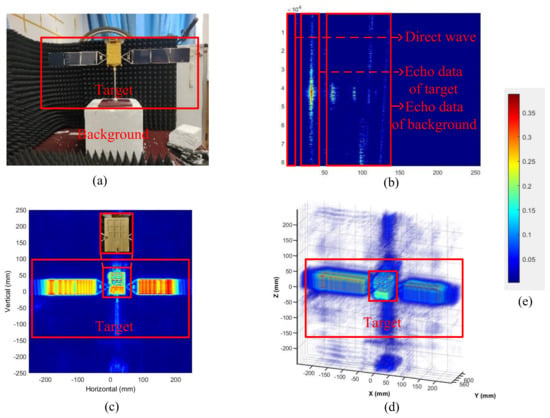
Figure 6.
Data processing results. (a) is the optical image; (b) is the image with pulse compression; (c) is the 2-D imaging result; (d) is the 3-D imaging result; (e) is the color label.
Obviously, from a viewpoint of visual effect, the detailed texture of the imaging results generated using RMA is obvious, the background is clear, and the nine grooves of the main part of the satellite model are visible. During the data collection process, the sailboards on both sides of the satellite model were not strictly perpendicular to the distance direction, so there was some angle error, and the corresponding positions in the imaging results were deformed. Compared with optical pictures, the radar imaging results are excellent. This also proves that the data collected by our experimental platform can be used for 3-D near-field high–resolution MMW radar imaging. From a viewpoint of image quality, the image entropy of RMA 2-D imaging results is , and the image contrast is . The entropy and contrast of optical images are and , respectively. In contrast, the entropy of near-field radar imaging results is only of the optical image, meaning that near-field radar imaging has a better focusing effect and lower complexity. This is because, in the process of radar radiation, the millimeter wave meets other objects in the area of the targets, such as clothes, foam, absorbing material, etc., or directly penetrates, be absorbed, or produces diffuse reflection; only the target echo that has strong scattering property returns radar receiver. Therefore, it has the effect of filtering the complex background, and the image entropy of the imaging results is greatly reduced. The image contrast decreased by , which indicated a loss of texture detail in radar imaging.
Figure 6d is the 3-D imaging results and proved that our data can achieve 3-D high-resolution near-field MMW imaging. It can be observed that in addition to the complete imaging target, there are strong grating lobe and side lobe clutter, which make the images blurred. The imaging quality can be improved through a better imaging algorithm, and our actual measurement data can meet the high-resolution imaging requirements.
According to the theory introduced in Section 2, it can be calculated that the resolution in the vertical and horizontal directions is ; this value is determined by the distance of the target and the size of the virtual aperture. Millimeter-scale resolution ensures high image resolution, and when the spacing between objects with different scattering properties is higher than in the plane, the image results are conspicuous, such as the grooves and sailboards on the satellite model. The range direction resolution is limited by the system bandwidth and is lower than that of the array plane direction. When transmitting a signal with bandwidth, the range direction resolution is about . The range direction resolution enhancement method [47,48] can be considered to improve the range-direction resolution, and there have been some detailed studies done by researchers in their work; however, this article does not cover them in detail.
3.2. Description of Dataset
This section comprehensively presents 3DRIED and analyzes the advantages of 3DRIED by comparing different environments, different algorithms, and different objectives. All the parameters of the experimental platform are set in Section 3.1, as shown in Table 1. The details of 3DRIED are described in Table 2.

Table 1.
The parameters of the experimental platform.

Table 2.
Description of the dataset.
3.2.1. Imaging Evaluation under Different Environments
When detecting metal targets and dangerous objects, such as firearms and knives, in the security inspection system, it will be affected by the concealment from clothing, leather bags, and other items. Conventional detection methods, such as visible light shooting, X-ray imaging, metal detection, and other methods, cannot meet the security inspection requirements, while millimeter waves rely on their low radiation, strong penetration, and high resolution and have great advantages in radar security inspection [49,50]. The echo data of the same target in different environments will be different. Here, we compare the imaging conditions of the pistol model in free space, in a carton, and in a backpack.
As shown in Figure 7, the scattering target is a metal pistol model, whose size is ; the vertical distance to the array plane is ; the size of imaging space is in x, y, and z axes, respectively. The imaging range is 53–63 in the y axis. Three-dimensional BPA is selected for imaging, and the 2-D imaging results are obtained by projecting the maximum value of the 3-D image in the plane. It can be seen that the pistol model has a clear outline in the 2-D and 3-D imaging results. Although the image obtained using the traditional BPA has a strong grating lobe and some background clutter, the target can still be distinguished in the imaging results. For the carton with a strong reflection property, the imaging area can also be distinguished. The more complex the scene environment, the more clutter, but the target with strong reflection characteristics can be prominent in the imaging space; that is, in a complex background, the target can be detected by MMW radar. For imaging under three different environmental conditions, the calculated values of image entropy and contrast are also reasonable, as shown in Table 3.
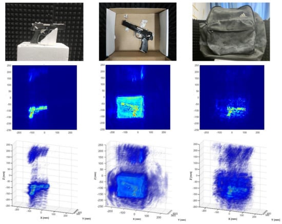
Figure 7.
Imaging results in different environments. Column 1 is a pistol in a normal environment; Column 2 is a pistol in the carton; Column 3 is a pistol in the backpack; Row 1 are the optical images of the target; Row 2 are 2-D BPA imaging results; Row 3 are 3-D BPA imaging results.

Table 3.
Quality evaluation of imaging results in different environments.
3.2.2. Imaging Evaluation Using Different Algorithms
In this part, we select BPA, RMA, CSA, and RMIST-Net to process the raw echo data. The essence of RMA is the multiplication operation in the frequency domain; BPA is the traversal and accumulation operation in the time domain; and the CSA is to solve the optimization problem by iteration to complete the sparse reconstruction. Because the compressed sensing algorithm can use a low sampling rate to complete the high-precision reconstruction of the sparse target, we set the sampling rate to . In order to have an intuitive visual comparison, we randomly downsample the echo data in RMA and select of the data. In addition, RMIST-Net is also used for imaging processing. As shown in Figure 8, the scattering target is a metal rifle model.
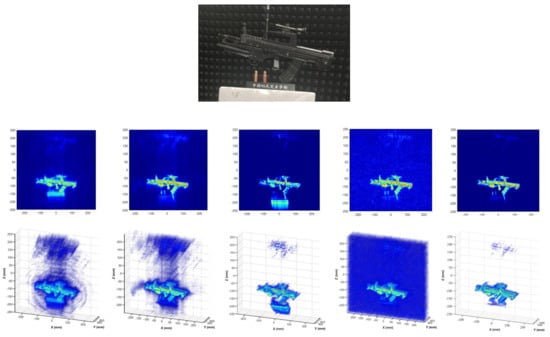
Figure 8.
Imaging results in different algorithms. Row 1 is the optical image; Row 2 are 2-D imaging results using different algorithms; Row 3 are 3-D imaging results using different algorithms; Column 1 are the results of BPA; Column 2 are the results of RMA with sampling rate; Column 3 are the results of CSA with sampling rate; Column 4 are the results of RMA with sampling rate; Column 5 are the results of RMIST-Net.
The size of target is , the vertical distance to the array plane is , the size of imaging space is in x, y, and z axes, respectively. The imaging range is 53–63 cm in the y axis. The 2-D imaging results are obtained by projecting the maximum value of the 3-D image in the plane. Besides, the number of iterations in CSA is 30, and the iteration phases of RMIST-Net are set to 3 by default.
According to the 2-D and 3-D imaging results in Figure 8, the images generated by BPA and RMA are clear, high-resolution, and accompanied by strong grating lobes and sidelobe clutter, and the calculated corresponding image entropy and contrast are also close. Under the condition of sampling rate, the image generated by CSA has a clear background and weak grating lobes, and the side lobes are also reduced to a very low level. In contrast, the image generated by RMA can observe the target, but because half of the sampled data is randomly lost, a strong image aliasing effect will occur. In other words, when imaging sparse targets, compressed sensing technology has more advantages than classic time-domain and frequency-domain algorithms. RMIST-Net reduces the grating lobes to a lower level, the target profile is clear, and the clutter is minimal. The high-resolution imaging ability of 3DRIED under different imaging algorithms has been verified, and it can also be used by researchers to verify their new algorithm theories. For imaging using four different algorithms, the calculated values of image entropy and contrast are also reasonable, as shown in Table 4.

Table 4.
Quality evaluation of imaging results in different algorithms.
3.2.3. Imaging Evaluation with Different Targets
The imaging effect of different targets is determined by many factors such as scattering properties, sparseness, environment, and so on. In this part, we show the 2-D and 3-D imaging results of some data using the mentioned algorithms and give the corresponding image quality indexes. The actual size of the imaging targets and other data are given in the next part. The vertical distance between the target and the radar sensor is 55–60 cm, the size of the imaging space is 50 cm × 10 cm × 50 cm in x, y, and z axes, and the imaging range of the distance direction is selected as 53–63 cm in the y axis, which is divided into 6 slices, and the interval of each slice is about . Figure 9, Figure 10 and Figure 11 show the optical images of nine targets. Figure 12, Figure 13 and Figure 14 show the data processing results, and here is a brief analysis.

Figure 9.
The optical images. Left is a plier; Middle is a stiletto; Right is a hammer.

Figure 10.
The optical images. Left is a concealed knife; Middle is a concealed snips; Right is concealed knife and stiletto.

Figure 11.
The optical images. Left is knife and stiletto; Middle is a snips; Right is a concealed rifle.
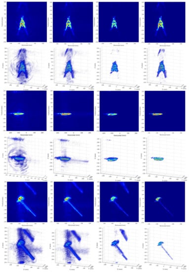
Figure 12.
Imaging results of different targets using different algorithms. (Rows 1, 2) are the results of a plier; (Rows 3, 4) are the results of a stiletto; (Rows 5, 6) are the results of a hammer. Rows and 5 are the 2-D imaging results; Rows and 6 are the 3-D imaging results; Column 1 is the BPA imaging results; Column 2 is the RMA imaging results; Column 3 is the CSA imaging results; Column 4 is the RMIST-Net imaging results.
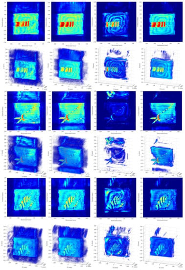
Figure 13.
Imaging results of different targets using different algorithms. (Rows 1, 2) are the results of the concealed knife; (Rows 3, 4) are the results of the concealed snips; (Rows 5, 6) are the results of the concealed knives. Rows and 5 are the 2-D imaging results; Rows and 6 are the 3-D imaging results; Column 1 is the BPA imaging results; Column 2 is the RMA imaging results; Column 3 is the CSA imaging results; Column 4 is the RMIST-Net imaging results.
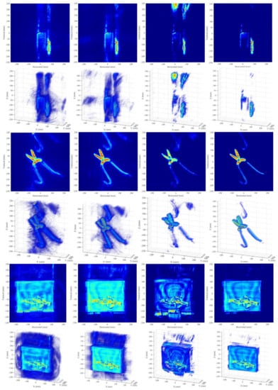
Figure 14.
Imaging results of different targets using different algorithms. (Rows 1, 2) are the results of knives; (Rows 3, 4) are the results of snips; (Rows 5, 6) are the results of the concealed rifle. Rows and 5 are the 2-D imaging results; Rows and 6 are the 3-D imaging results; Column 1 is the BPA imaging results; Column 2 is the RMA imaging results; Column 3 is the CSA imaging results; Column 4 is the RMIST-Net imaging results.
Observing the images, for the scattering targets with strong scattering properties in the imaging space, the outline can be observed in the reconstructed image. The grating lobes and sidelobe clutter of the image obtained by different algorithms are different, which is reflected in the cleanness of the background. The sidelobes generated by traditional BPA and RMA are relatively heavy. The operation of using the window function can be effective for reducing side lobes clutter, but at the same time, it will bring about effects such as main lobe broadening. This article will not do further research. The imaging results obtained by CSA can see that the grating lobe has been reduced, and the sidelobe clutter is almost invisible. This is a high-resolution imaging result at the expense of the running efficiency of the algorithm. The algorithm is complex, and the computation burden is very large. Since CSA has a poor tolerance for weakly sparse or non-sparse targets, in order to get better imaging results, in actual processing, the sampling rate of sparse scattering targets is set to , and the sampling rate of the weakly sparse or non-sparse scattering target is set to . Compared with them, RMIST-Net can reduce the grating lobes and sidelobe clutter without sacrificing the computation efficiency in order to maintain a clear profile facing the targets for different sparse properties. The advantage of using the deep unfolding network to reconstruct radar signals is reflected here.
In addition, some rules can also be found in the entropy and contrast of the image. The image entropy and contrast of the imaging results obtained by BPA and RMA are similar, and their image details and clutter level are also similar; however, the image entropy and contrast of the results obtained using CSA are greatly reduced compared with the two results, corresponding to the details loss and clutter reduction. The effect of CSA under sampling rate is superior to that of BPA and RMA under sampling rate. Under the premise of ignoring the calculation burden, it reflects the superiority of the compressed sensing theory. The image entropy and contrast of the imaging results obtained by RMIST-Net are at an excellent level, and the image quality is the highest. The problems of imaging accuracy and the computing burden are solved by deep neural networks at the same time. Quality evaluation of imaging results from different targets using different algorithms is shown in Table 5.

Table 5.
Quality evaluation of imaging results of different targets in different algorithms.
3.3. Analysis of Running Time
The aforementioned experiments are all run in a unified configuration with the CPU-Intel(R) Core(TM) i7-7700K CPU @ 4.20 GHz (64 GB RAM) and the GPU-NVIDIA GeForce GTX 1080 Ti. In Table 6, the running time of the imaging processing for the hammer in Section 3.2.3 is reported as a representative. Obviously, RMA and RMIST-Net have a huge advantage in reducing the computational burden, and GPU has a superior acceleration effect facing to large-scale radar data operation. BPA needs approximate 1.97 h to complete a 3-D imaging processing using CPU. By contrast, RMIST-Net costs just 0.09 s under GPU, which is a difference of 80,000 times.

Table 6.
Running time under different algorithms.
3.4. Discussion
3DRIED contains a total of 81 different near-field MMW radar echo data; the details are shown in Table 2. According to the target category, there are 9 types of echo data, which are knives, guns, and other dangerous metal objects; according to the scene condition, there are 3 types of echo data, which are placed in the free sense, placed in the carton, and placed in the backpack; according to the number of targets, there are 2 types of targets, which are single target and multiple targets.
The whole file includes the bin file sampled by ADC, the raw data file output as mat format, the optical image of the target, and the reconstructed images generated by near-field MMW 3-D imaging algorithms. The numerical evaluation of high-resolution images is also given as baselines. Significantly, the 81 items of raw echo data that have been collected from the near-field MMW 3-D imaging system are all real, effective, and reliable. Targets types are complete, environments conditions are diverse, and applications are extensive.
4. Conclusions
In this paper, we propose a 3-D near-field MMW radar dataset 3DRIED—an experimental platform that can obtain 3-D information about the target built in combination with the SAR system and broadband MMW. The raw echo data of different targets in different environments are collected, and high-resolution 2-D and 3-D imaging results are obtained. Part of the results is shown in Section 4. We choose the BPA in the time domain, the RMA in the frequency domain, the CSA using the compressed sensing theory, and the deep neural networks RMIST-Net, which verified the completeness of 3DRIED in imaging with different algorithm theories. Different numerical evaluation indexes are given as a baseline here. The measured data of high-resolution MMW radar is precious. Our goal is to provide an effective and reliable dataset for the research field, which is conducive to the promotion of algorithm research using near-field radar data. The measured data in the subsequent work will also be extended to 3DRIED, hoping to make some contributions to the research field.
Author Contributions
Conceptualization, Z.Z. and S.W.; methodology, Z.Z. and M.W.; software, S.L. and Z.Z.; validation, X.Z. and J.W.; formal analysis, S.W. and M.W.; investigation, X.Z.; resources, S.W.; data curation, J.S.; writing—original draft preparation, Z.Z.; writing—review and editing, Z.Z.; visualization, Z.Z. and J.W.; supervision, F.F.; project administration, S.W.; funding acquisition, S.W. All authors have read and agreed to the published version of the manuscript.
Funding
This research was funded by the National Key Research and Development Program of China (2017YFB0502700), the National Natural Science Foundation of China (61501098), and the High-Resolution Earth Observation Youth Foundation (GFZX04061502).
Institutional Review Board Statement
Not applicable.
Informed Consent Statement
Not applicable.
Data Availability Statement
Not applicable.
Acknowledgments
The authors would like to thank the anonymous reviewers and editors for their selfless help to improve our manuscript.
Conflicts of Interest
The authors declare no conflict of interest.
References
- Gu, S.; Li, C.; Gao, X.; Sun, Z.; Fang, G. Three-dimensional image reconstruction of targets under the illumination of terahertz Gaussian beam—Theory and experiment. IEEE Trans. Geosci. Remote. Sens. 2012, 51, 2241–2249. [Google Scholar] [CrossRef]
- Gao, J.; Deng, B.; Qin, Y.; Li, X.; Wang, H. Point cloud and 3-D surface reconstruction using cylindrical millimeter-wave holography. IEEE Trans. Instrum. Meas. 2019, 68, 4765–4778. [Google Scholar] [CrossRef]
- Guo, Q.; Wang, Z.; Chang, T.; Cui, H.L. Millimeter-wave 3-D imaging testbed with MIMO array. IEEE Trans. Microw. Theory Tech. 2019, 68, 1164–1174. [Google Scholar] [CrossRef]
- Zhu, Z.; Xu, F. Demonstration of 3-D Security Imaging at 24 GHz With a 1-D Sparse MIMO Array. IEEE Geosci. Remote. Sens. Lett. 2020, 17, 2090–2094. [Google Scholar] [CrossRef]
- Zhuge, X.; Yarovoy, A.G. A sparse aperture MIMO-SAR-based UWB imaging system for concealed weapon detection. IEEE Trans. Geosci. Remote. Sens. 2010, 49, 509–518. [Google Scholar] [CrossRef]
- Sheen, D.M.; McMakin, D.L.; Hall, T.E. Three-dimensional mmW imaging for concealed weapon detection. IEEE Trans. Microw. Theory Tech. 2001, 49, 1581–1592. [Google Scholar] [CrossRef]
- Yarovoy, A.G.; Savelyev, T.G.; Aubry, P.J.; Lys, P.E.; Ligthart, L.P. UWB array-based sensor for near-field imaging. IEEE Trans. Microw. Theory Tech. 2007, 55, 1288–1295. [Google Scholar] [CrossRef]
- Ren, Z.; Boybay, M.S.; Ramahi, O.M. Near-field probes for subsurface detection using split-ring resonators. IEEE Trans. Microw. Theory Tech. 2010, 59, 488–495. [Google Scholar] [CrossRef]
- Klemm, M.; Leendertz, J.A.; Gibbins, D.; Craddock, I.J.; Preece, A.; Benjamin, R. Microwave radar-based differential breast cancer imaging: Imaging in homogeneous breast phantoms and low contrast scenarios. IEEE Trans. Antennas Propag. 2010, 58, 2337–2344. [Google Scholar] [CrossRef]
- Chao, L.; Afsar, M.N.; Korolev, K.A. Millimeter wave dielectric spectroscopy and breast cancer imaging. In Proceedings of the 2012 7th European Microwave Integrated Circuit Conference, Amsterdam, The Netherlands, 29–30 October 2012; pp. 572–575. [Google Scholar]
- Di Meo, S.; Matrone, G.; Pasian, M.; Bozzi, M.; Perregrini, L.; Magenes, G.; Mazzanti, A.; Svetlo, F.; Summers, P.E.; Renne, G.; et al. High-resolution mm-wave imaging techniques and systems for breast cancer detection. In Proceedings of the 2017 IEEE MTT-S International MicrowaveWorkshop Series on Advanced Materials and Processes for RF and THz Applications (IMWS-AMP), Pavia, Italy, 20–22 September 2017; pp. 1–3. [Google Scholar]
- Tokoro, S. Automotive application systems of a millimeter-wave radar. In Proceedings of the Conference on Intelligent Vehicles, Tokyo, Japan, 19–20 September 1996; pp. 260–265. [Google Scholar]
- Ihara, T.; Fujimura, K. Research and development trends of mmW short-range application systems. IEICE Trans. Commun. 1996, 79, 1741–1753. [Google Scholar]
- Kharkovsky, S.; Zoughi, R. Microwave and millimeter wave nondestructive testing and evaluation-Overview and recent advances. IEEE Instrum. Meas. Mag. 2007, 10, 26–38. [Google Scholar] [CrossRef]
- Cutrona, L.J. Synthetic aperture radar. Radar Handb. 1990, 2, 2333–2346. [Google Scholar]
- Yanik, M.E.; Wang, D.; Torlak, M. Development and demonstration of MIMO-SAR mmWave imaging testbeds. IEEE Access 2020, 8, 126019–126038. [Google Scholar] [CrossRef]
- Yegulalp, A.F. Fast backprojection algorithm for synthetic aperture radar. In Proceedings of the 1999 IEEE Radar Conference. Radar into the Next Millennium (Cat. No. 99CH36249), Waltham, MA, USA, 22 April 1999; pp. 60–65. [Google Scholar]
- Mohammadian, N.; Furxhi, O.; Short, R.; Driggers, R. SAR millimeter wave imaging systems. Passive and Active Millimeter-Wave Imaging XXII. Int. Soc. Opt. Photonics 2019, 10994, 109940A. [Google Scholar]
- Moll, J.; Schops, P.; Krozer, V. Towards three-dimensional millimeter-wave radar with the bistatic fast-factorized back-projection algorithm—Potential and limitations. IEEE Trans. Terahertz Sci. Technol. 2012, 2, 432–440. [Google Scholar] [CrossRef]
- Lopez-Sanchez, J.M.; Fortuny-Guasch, J. 3-D radar imaging using range migration techniques. IEEE Trans. Antennas Propag. 2000, 48, 728–737. [Google Scholar] [CrossRef]
- Wang, Z.; Guo, Q.; Tian, X.; Chang, T.; Cui, H.L. Near-field 3-D millimeter-wave imaging using MIMO RMA with range compensation. IEEE Trans. Microw. Theory Tech. 2018, 67, 1157–1166. [Google Scholar] [CrossRef]
- Candes, E.J.; Tao, T. Near-optimal signal recovery from random projections: Universal encoding strategies? IEEE Trans. Inf. Theory 2006, 52, 5406–5425. [Google Scholar] [CrossRef] [Green Version]
- Candes, E.J.; Romberg, J.K.; Tao, T. Stable signal recovery from incomplete and inaccurate measurements. Commun. Pure Appl. Math. J. Issued Courant Inst. Math. Sci. 2006, 59, 1207–1223. [Google Scholar]
- Baraniuk, R.G. Compressive sensing [lecture notes]. IEEE Signal Process. Mag. 2007, 24, 118–121. [Google Scholar] [CrossRef]
- Baron, D.; Sarvotham, S.; Baraniuk, R.G. Bayesian compressive sensing via belief propagation. IEEE Trans. Signal Process. 2009, 58, 269–280. [Google Scholar] [CrossRef] [Green Version]
- Bobin, J.; Starck, J.L.; Ottensamer, R. Compressed sensing in astronomy. IEEE J. Sel. Top. Signal Process. 2008, 2, 718–726. [Google Scholar] [CrossRef] [Green Version]
- Lustig, M.; Donoho, D.L.; Santos, J.M.; Pauly, J.M. Compressed sensing MRI. IEEE Signal Process. Mag. 2008, 25, 72–82. [Google Scholar] [CrossRef]
- Zhang, J.; Ghanem, B. ISTA-Net: Interpretable optimization-inspired deep network for image compressive sensing. In Proceedings of the IEEE Conference on Computer Vision and Pattern Recognition, Salt Lake City, UT, USA, 18–22 June 2018; pp. 1828–1837. [Google Scholar]
- Zhang, Z.; Liu, Y.; Liu, J.; Wen, F.; Zhu, C. AMP-Net: Denoising-based deep unfolding for compressive image sensing. IEEE Trans. Image Process. 2020, 30, 1487–1500. [Google Scholar] [CrossRef] [PubMed]
- Wang, M.; Wei, S.; Shi, J.; Wu, Y.; Qu, Q.; Zhou, Y.; Zeng, X.; Tian, B. CSR-Net: A novel complex-valued network for fast and precise 3-D microwave sparse reconstruction. IEEE J. Sel. Top. Appl. Earth Obs. Remote Sens. 2020, 13, 4476–4492. [Google Scholar] [CrossRef]
- Wang, M.; Wei, S.; Liang, J.; Zeng, X.; Wang, C.; Shi, J.; Zhang, X. RMIST-Net: Joint Range Migration and Sparse Reconstruction Network for 3-D mmW Imaging. IEEE Trans. Geosci. Remote. Sens. 2021. [Google Scholar] [CrossRef]
- Wang, M.; Wei, S.; Liang, J.; Liu, S.; Shi, J.; Zhang, X. Lightweight FISTA-Inspired Sparse Reconstruction Network for mmW 3-D Holography. IEEE Trans. Geosci. Remote. Sens. 2021. [Google Scholar] [CrossRef]
- Wang, Z.; Miao, X.; Huang, Z.; Luo, H. Research of Target Detection and Classification Techniques Using Millimeter-Wave Radar and Vision Sensors. Remote Sens. 2021, 13, 1064. [Google Scholar] [CrossRef]
- Cui, J.; Ding, Z.; Fan, P.; Al-Dhahir, N. Unsupervised machine learning-based user clustering in millimeter-wave-NOMA systems. IEEE Trans. Wirel. Commun. 2018, 17, 7425–7440. [Google Scholar] [CrossRef]
- Lien, J.; Gillian, N.; Karagozler, M.E.; Amihood, P.; Schwesig, C.; Olson, E.; Raja, H.; Poupyrev, I. Soli: Ubiquitous gesture sensing with millimeter wave radar. ACM Trans. Graph. (TOG) 2016, 35, 1–19. [Google Scholar] [CrossRef] [Green Version]
- Long, N.; Wang, K.; Cheng, R.; Hu, W.; Yang, K. Unifying obstacle detection, recognition, and fusion based on millimeter wave radar and RGB-depth sensors for the visually impaired. Rev. Sci. Instrum. 2019, 90, 044102. [Google Scholar] [CrossRef]
- Zhao, K.; Wang, J. Improved wiener filter super-resolution algorithm for passive millimeter wave imaging. In Proceedings of the 2011 IEEE CIE International Conference on Radar, Chengdu, China, 24–27 October 2011; Volume 2, pp. 1768–1771. [Google Scholar]
- Li, H.; Liang, X.; Zhang, F.; Wu, Y. 3D imaging for array InSAR based on Gaussian mixture model clustering. J. Radars 2017, 6, 630–639. [Google Scholar]
- Shi, J.; Que, Y.; Zhou, Z.; Zhou, Y.; Zhang, X.; Sun, M. Near-field Millimeter Wave 3D Imaging and Object Detection Method. J. Radars 2019, 8, 578–588. [Google Scholar]
- Kramer, A.; Harlow, K.; Williams, C.; Heckman, C. ColoRadar: The Direct 3D Millimeter Wave Radar Dataset. arXiv 2021, arXiv:2103.04510. [Google Scholar]
- Zhuge, X.; Yarovoy, A.G. Three-dimensional near-field MIMO array imaging using range migration techniques. IEEE Trans. Image Process. 2012, 21, 3026–3033. [Google Scholar] [CrossRef]
- Gao, J.; Qin, Y.; Deng, B.; Wang, H.; Li, X. Novel efficient 3D short-range imaging algorithms for a scanning 1D-MIMO array. IEEE Trans. Image Process. 2018, 27, 3631–3643. [Google Scholar] [CrossRef] [PubMed]
- Wei, S.J.; Zhang, X.L.; Shi, J. Sparse autofocus via Bayesian learning iterative maximum and applied for LASAR 3-D imaging. In Proceedings of the 2014 IEEE Radar Conference, Cincinnati, OH, USA, 19–23 May 2014. [Google Scholar]
- Building Cascade Radar Using TI’s mmwave Sensors, Texas Instruments. Available online: Https://training.ti.com/build-cascadedradar-usingtis-mmwave-sensors (accessed on 9 April 2018).
- Gumbmann, F.; Schmidt, L.P. Millimeter-wave imaging with optimized sparse periodic array for short-range applications. IEEE Trans. Geosci. Remote. Sens. 2011, 49, 3629–3638. [Google Scholar] [CrossRef]
- Zhang, S.; Liu, Y.; Li, X. Fast entropy minimization based autofocusing technique for ISAR imaging. IEEE Trans. Signal Process. 2015, 63, 3425–3434. [Google Scholar] [CrossRef]
- Qiao, L.; Wang, Y.; Zhao, Z.; Chen, Z. Range resolution enhancement for three-dimensional millimeter-wave Wholographic imaging. IEEE Antennas Wirel. Propag. Lett. 2015, 15, 1422–1425. [Google Scholar] [CrossRef]
- Gao, J.; Qin, Y.; Deng, B.; Wang, H.; Li, X. A novel method for 3-D millimeter-wave holographic reconstruction based on frequency interferometry techniques. IEEE Trans. Microw. Theory Tech. 2017, 66, 1579–1596. [Google Scholar] [CrossRef]
- Appleby, R.; Anderton, R.N. Millimeter-wave and submillimeter-wave imaging for security and surveillance. Proc. IEEE 2007, 95, 1683–1690. [Google Scholar] [CrossRef]
- McMakin, D.L.; Sheen, D.M.; Collins, H.D. Remote concealed weapons and explosive detection on people using mmW holography. In Proceedings of the 1996 30th Annual International Carnahan Conference on Security Technology, Lexington, KY, USA, 2–4 October 1996; pp. 19–25. [Google Scholar]
Publisher’s Note: MDPI stays neutral with regard to jurisdictional claims in published maps and institutional affiliations. |
© 2021 by the authors. Licensee MDPI, Basel, Switzerland. This article is an open access article distributed under the terms and conditions of the Creative Commons Attribution (CC BY) license (https://creativecommons.org/licenses/by/4.0/).