Article

Application of Seismic Interferometry by Multidimensional Deconvolution to Earthquake Data Recorded in Malargüe, Argentina

by
Faezeh Shirmohammadi
1,2,*,
Deyan Draganov
1,
Mohammad Reza Hatami
2 and
Cornelis Weemstra
1
1
Department of Geoscience and Engineering, Delft University of Technology, 2628 CN Delft, The Netherlands
2
Institute of Geophysics, University of Tehran, Tehran 14359-44411, Iran
*
Author to whom correspondence should be addressed.
Remote Sens. 2021, 13(23), 4818; https://doi.org/10.3390/rs13234818
Submission received: 18 October 2021 / Revised: 11 November 2021 / Accepted: 22 November 2021 / Published: 27 November 2021
(This article belongs to the Special Issue Advances in Seismic Interferometry)

Abstract

:
Seismic interferometry (SI) refers to the principle of generating new seismic responses using crosscorrelations of existing wavefield recordings. In this study, we report on the use of a specific interferometric approach, called seismic interferometry by multidimensional deconvolution (SI by MDD), for the purpose of retrieving surface-wave responses. In theory, SI by MDD suffers less from irregularities in the distribution of (passive) sources than conventional SI. Here, we confirm this advantage for the application to surface waves originating from regional earthquakes close to Central Chile. For that purpose, we use the Malargüe seismic array in Argentina. This T-shaped array consists of two perpendicular lines of stations, which makes it rather suitable for the application of SI by MDD. Comparing the responses retrieved through SI by MDD to the responses retrieved using conventional SI, we find that the application of SI by MDD results in surface-wave responses that are both more accurate and more stable than surface-wave responses that are retrieved using conventional SI. That is, our results demonstrate that SI by MDD suffers less from non-uniformly distributed earthquakes and differences in the power spectra of earthquake responses. In addition, we show that SI by MDD mitigates the effect of site amplification on the retrieved surface waves.

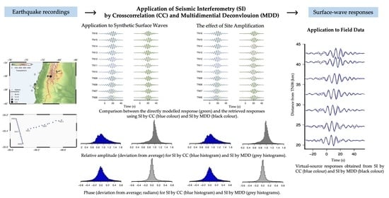
Graphical Abstract

1. Introduction

Seismic interferometry (SI) is a powerful tool for generating responses between receivers. It allows one to turn a receiver into a so-called virtual source, the response of which is retrieved at other receivers [1,2]. SI has been applied to recordings of diffuse fields, such as coda waves [3] and ambient noise [4,5,6], and data from transient fields, such as earthquake records [7] and active-source data [8,9,10]. This technique can be used to retrieve, among others, body- and surface-wave responses, both of which have played an important role in seismology, as they can provide key information about the Earth’s interior.
For the specific case of surface-wave imaging and/or monitoring, it is important to be able to retrieve reliable surface-wave responses. Surface waves have become particularly important in near-surface geophysics [11,12,13]. In this case, the local geological condition or so-called site amplification has a great impact on the seismic ground motion [14,15], making accurate retrieval of surface waves particularly challenging. Whereas most interferometric studies in seismology rely solely on crosscorrelations, we will, in this study, use a more advanced interferometric technique called SI by multidimensional deconvolution (MDD) (e.g., [16]).
SI by crosscorrelation (CC) relies on specific assumptions. Among others, the medium is assumed to be lossless, and the receivers are assumed to be illuminated uniformly by sufficiently densely placed sources (passive or active). In practical situations, these assumptions are often not met. To overcome these limitations and to enhance resolution, several other interferometric approaches have been proposed. These include SI by crossconvolution [17,18], trace deconvolution [19], and MDD [20,21]. Notably, the latter technique is derived based on a reciprocity theorem of the convolution type, which allows it to be applied to dissipative media (e.g., [6]). SI by MDD allows one to correct for possible erroneous retrieval in the virtual-source responses retrieved using (the conventional) SI by CC. Intuitively, this can be shown by representing the MDD retrieval as the conventional CC result compensated by a deconvolution operator, also called point-spread function, which can be built from the recordings themselves (e.g., [6]). In this study, however, deconvolution is achieved by means of singular-value decomposition (SVD).
Admittedly, SI by MDD is not without constraints. First, it requires a regularly sampled receiver array. Contrary to SI by CC, it can therefore not be applied to individual receiver couples. Second, the MDD process is potentially unstable because the inversion problem may be ill-posed, which implies it demands a stabilization procedure. Notwithstanding, it has been shown in several applications that SI by MDD may outperform SI by CC. Minato et al. [22], for example, demonstrated this for the retrieval of reflection responses between two boreholes. Van Dalen et al. [23] applied SI by MDD to retrieve the full surface-wave response, including the higher modes. Hartstra et al. [24] applied full-field MDD to retrieve the complete reflection response without free-surface multiples from sparse passive sources. Weemstra et al. [6] applied SI by MDD to recordings of the vertical particle velocity of ambient seismic noise and showed that more accurate phase-velocity estimates and more stable time-lapse responses are obtained. Draganov et al. [25] applied MDD to active-source recordings for retrieval of reflections and the consecutive imaging of a wooden board.
The main objective of this study is to investigate and improve the accuracy of interferometric surface waves retrieved from surface-wave energy from regional earthquakes. In this context, we also demonstrate the effect of site amplification on the retrieved surface waves. We compare the responses retrieved using SI by MDD to the responses retrieved using SI by CC. In particular, we introduce SVD into SI by MDD in a surface-wave context. This is analogous to Minato et al. [22,26], who showed that truncated SVD improves the reliability of the retrieved wavefield in a crosswell context.
In this study, we exploit surface waves recorded by the Malargüe array (MalAR-Rgue) in Argentina [27]. So far, the data from MalARRgüe have been used with the global-phase H/V spectral ratio method to identify the fundamental resonance frequencies of the receiver-side structure in the Malargüe region and to detect tectonic tremors [28,29], as well as for several interferometric applications with local, regional, and global earthquake responses [30,31,32,33]. It has also been used with SI for retrieval of surface waves from ambient noise using CC [34] and MDD [6]. The MalARRgüe effectively consist of two separate seismic arrays [27]. The T-shaped geometry and station spacing of one of these two arrays makes it particularly well suited for the application of SI by MDD to surface waves. In this study, we first utilize synthetic surface waves associated with 11 favourably located regional earthquakes to test the proposed methodology. After testing the procedure on the synthetic surface waves, we utilize the actual surface waves generated by 11 regional earthquakes with magnitude range 4.1–6.0.
In the following, we first give a brief overview of the theory behind SI by CC, MDD, and the formulation underlying our models. We then continue with a brief introduction of MalARRgüe. In Section 4, we present the numerical-modelling results of SI by CC and SI by MDD and their comparison for the different frequency ranges. Additionally, we investigate the effect of site amplification using the interferometric results. We then apply SI by CC and MDD to the field earthquake recordings and compare them. Finally, we show that the application of SI by MDD results in retrieved surface-wave responses that are more accurate than the responses retrieved using SI by CC because SI by MDD partly compensates for the irregularity in the source distribution and power.

2. Method

In this study, we focus on fundamental-mode surface waves. Using the Fourier convention f ^ ( ω ) = 1 2 π + f ( t ) e i ω t d t , the fundamental-mode surface-wave Green’s function for vertical particle velocity at x A , due to a vertical impulsive point source at x S , reads [10,35]
G ^ ( x A ,   x S ) = ω 4 A ^ c ^ H 0 ( 2 ) ( k ^ | x A x S | )
Here, ω is the angular frequency; c ^ indicates the Rayleigh-wave frequency-dependent phase velocity; k ^ is the frequency-dependent wavenumber, which, in a lossless medium, coincides with ω / c ^ ; and H 0 ( 2 ) is a zeroth-order Hankel function of the second kind. In general, frequency dependence is indicated by a hat, for example, f ^ f ( ω ) . For both receivers and sources located at the Earth’s surface, all locations are uniquely defined by their x 1 and x 2 coordinates, i.e., x A ( x A 1 , x A 2 ) . Furthermore, we refer to as a frequency-dependent modal scale factor, which is defined as [10]
A ^ 2 U ^ I 1 r 2 2 ( 0 )
where U ^ is the Rayleigh-wave group velocity, I 1 is its modal kinetic energy, and r 2 ( 0 ) is the value of the modal eigenfunction at the Earth’s surface.
Assuming wavefield observations by receivers at x A and x B , due to a multitude of sources at x S i , we define the crosscorrelation function (CCF) as
C ^ ( x A , x B ) i   v ^ ( x A , x S i ) v ^ * ( x B , x S i )
Here, v ^ ( x A , x S i ) and v ^ ( x B , x S i ) represent recordings of vertical-component particle velocity at x A and x B , respectively, due to a vertical-point source at x S i . The asterisk in Equation (3) denotes complex conjugation, and hence, the product on the right-hand side corresponds to CC in the time domain. Furthermore, for any location, x , a recording, v ^ ( x , x S i ) , represents G ^ ( x , x S i )   s ^ ( x S i ) , where s ^ ( x S i ) is the spectrum of the signal emitted by the source at x S i .
Considering the configuration in Figure 1a, where only the sources depicted in black emit signals, the relation between the Green’s function and CC is given by (Linder et al., 2018)
C ^ ( x A ,   x B ) = 1 A ^ G ^ ( x A ,   x B ) S ^
where S ^ denotes the power spectrum of the sources. Equation (4) is strictly valid for one-sided illumination, i.e., C ^ ( x A , x B ) is exclusively due to a summation over the black sources in Figure 1a. This implies that in the time domain, CC does not contain the so-called ‘acausal signal’ (e.g., [6]). The relation between the CCF and the Green’s function in Equation (4) is quite accurate in case the medium is lossless and the surface along which the sources are regularly placed is located in the far field of the receivers [2]. As such, this relation allows one to retrieve an estimate of the medium’s Green’s function (e.g., [13,36]) and hence underlies SI by CC [2].
Let us now introduce SI by MDD, which, contrary to SI by CC, neither requires the (one-sided) illumination to be uniform nor the medium to be lossless. The latter is a consequence of the fact that the formulation underlying SI by MDD is derived from a convolution-type Green’s function representation [21]. Let us consider the configuration in Figure 1b, where the receiver at x A and the receivers at x along S r e c are illuminated non-uniformly by the sources at x S i . For each of these sources, it can be shown that [10,37]
v ^ ( x A ,   x S i     ) = 2 A ^ S r e c   G ^ d ( x A , x ) v ^ ( x , x S i ) d x
Here, G ^ d is a so-called dipole Green’s function, which is defined as [10]
G ^ d ( x A , x   ) i c ^ ω G ^ ( x A , x   ) · n
where G ^ ( x A , x   ) is the spatial derivative of G ^ ( x A , x   ) , n = ( n 1 , n 2 ) is the outward pointing normal vector, and i is the imaginary unit.
Retrieval of the objective dipole Green’s function G ^ d ( x A , x   ) is what is referred to as SI by MDD. Importantly, G ^ d ( x A , x   ) is associated with a reference medium for which absorbing boundary conditions are valid along S r e c (for details, we refer to [16,37]). In practice, this means that Equation (5) only holds for waves traversing S r e c from the region containing the x S i into the region containing x A . This condition therefore implies that without explicit wavefield separation along S r e c , SI by MDD is only applicable to configurations where the medium is illuminated from a single side [21] and where no energy scatters back through S r e c . For our assumed single-mode surface waves and a configuration where the sources at x S i and the receiver at x A are located on opposite sides of S r e c , this condition is fulfilled.
Equation (5) holds for each x S i individually. By considering a multitude of sources, however, a set of equations is obtained. By replacing the integral over the virtual sources along S r e c with a summation and denoting the column vector containing the observed wavefield at x A (due to sources at x S i ) by v A , the column vector containing the objective wavefield G ^ d   by g d and the matrix containing the v ^ ( x , x S i ) by V B , this set of equations can be written as [26]
v A = V B g d
The number of rows and columns of V B coincides with the number of transient sources, N, and the number of receivers, M, along S r e c , respectively. Note that in our case, M is the number of stations along the north-south oriented receiver line, and N is the number of earthquakes. The objective wavefield, g d , is estimated using the pseudoinverse of V B , which we denote by V B 1 , through
g d ( est ) = V B 1 v A
In practice, Equation (8) presents an ill-posed problem, which is also the reason that we introduced g d ( est ) . Usually, ill-posedness is tackled by means of a damped least-squares inversion (Tikhonov regularization) [16,38]. In this study, however, we use SVD to estimate G ^ d ( x A , x ) .
The use of SVD reduces data redundancy and improves the accuracy of the estimated G ^ d ( x A , x ) . Substituting the Moore-Penrose pseudoinverse V B + for V B 1 , Equation (8) may be rewritten as [26]
g d ( est ) = V B + v A = V ( Δ r 1 0 0 0 ) U v A
The matrices V, U, and Δr can be obtained by applying SVD to the matrix V B   . In this work, we have implemented the SVD procedure in the frequency domain and have selected singular values for each frequency separately. The matrix V is a right singular matrix, the matrix U a left singular matrix, and matrix Δr is a diagonal matrix whose (diagonal) components are the nonzero singular values ordered from large to small, where r indicates the rank of the matrix V B   .
We define the percentage of energy associated with the i largest singular values as
S i = j i λ j j   λ j 100  
where λ j corresponds to the jth singular value and where the summation in the denominator is over all (non-zero) singular values. The rank associated with a specific threshold, S, is subsequently defined as that singular value, i, for which S i exceeds S [26]. Depending on the amount of noise, the threshold, S, can be set to different values to avoid the amplification of this noise in the pseudoinverse procedure [26].
After introducing the MalARRgüe, we will compare the stability of virtual-source responses retrieved through the application of SI by CC to the stability of the virtual-source responses retrieved through the application of SI by MDD. In particular, we focus on the ability to infer near-surface effects from the retrieved responses.

3. MalARRgüe

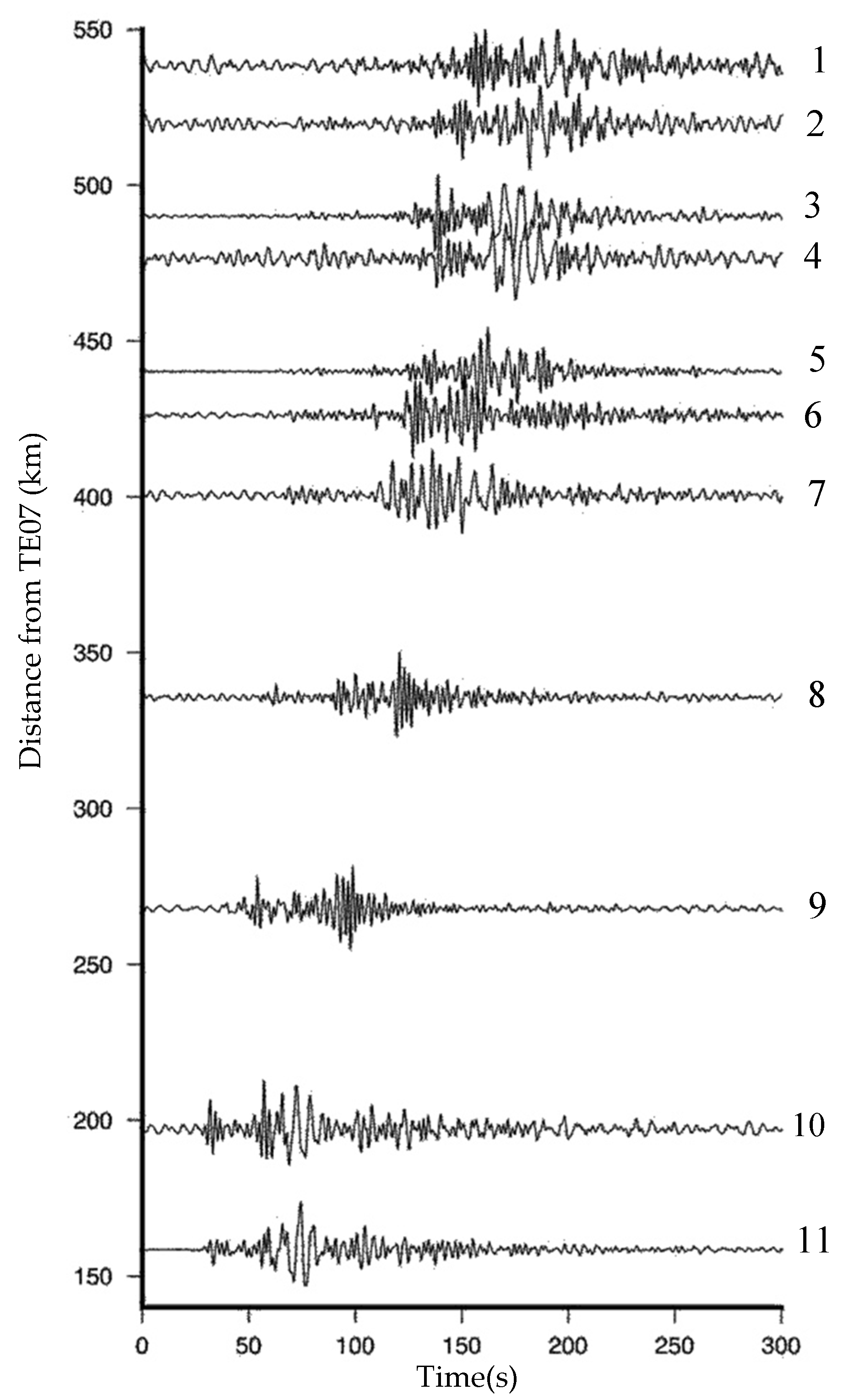
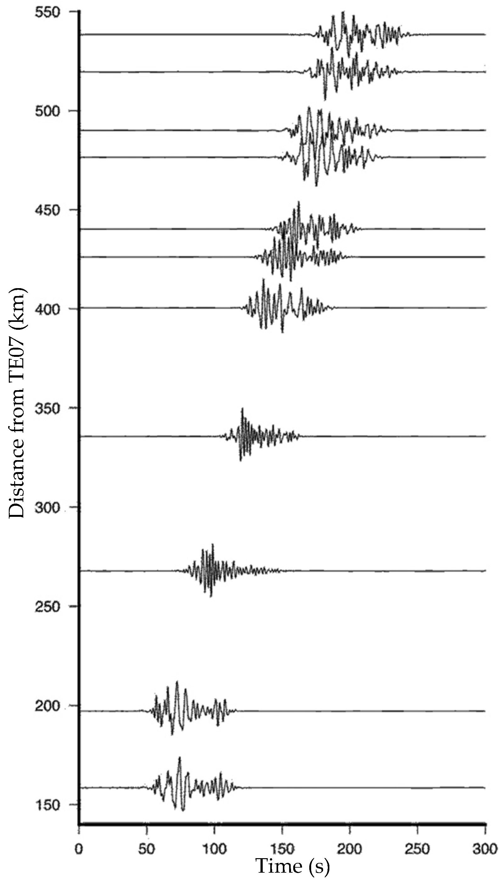
At the beginning of 2012, the large temporary seismic array MalARRgüe was installed in the Malargüe region, Mendoza, Argentina (Figure 2a). MalARRgüe consisted of two subarrays—a P-array, installed at a volcano and a T-array [27]. The latter array was centred at about 35° 24′S, 69° 27′W. The T-array consisted of two lines (Figure 2b)—the TN line with 20 stations of 2 km spacing oriented in NNW-SSE direction and the TE line with 13 stations of 4 km spacing oriented in WSW-ENE direction. The station spacing makes this array very suitable for interferometric surface-wave retrieval, for which it was partly designed [27]. The stations continuously recorded the seismic field during the deployment period, including earthquake activity. In this work, we only utilize the surface waves generated by 11 regional earthquakes. These 11 earthquakes are favourably located when it comes to the application of SI by MDD. The spatial distribution of these earthquakes is shown in Figure 2a; detailed information of these earthquakes is listed in Table 1. Figure 3 shows the recordings of these earthquakes by station TE07.
As we have shown in the previous section, SI by MDD requires a line (or contour) of stations (virtual sources) positioned such that all surface-wave energy traverses this line prior to arrival at the receiver at which we aim to retrieve the virtual-source responses. In this work, we turn the TN stations into virtual sources and retrieve their responses at the TE stations.
Strictly speaking, the nominal station spacing of 2 km implies a minimum surface-wave wavelength of 4 km (Nyquist criterion). Because the straight rays connecting the epicentres of the earthquakes with the T-array are almost perpendicular to the TN-line, and because we windowed the direct surface waves generated by these earthquakes, this threshold can be somewhat relaxed. Consequently, in this study, we evaluate the stability of the virtual-source responses up to a frequency of 0.5 Hz.

4. Application to Data and Results

In this section, we compare virtual-source responses retrieved through the application of SI by MDD to virtual-source responses retrieved through the application of SI by CC. In particular, we focus on the stability of responses in terms of phase and amplitude. Importantly, in this context, prior to application of SI, we normalize, for each earthquake individually, all surface-wave recordings with respect to the surface waves recorded by station TN11 (the reference station). As such, we effectively downweigh the contribution of strong earthquakes and increase the weight of small events in the stacking process implicit in the interferometric approach (either SI by CC or MDD). In other words, the normalization causes each earthquake to weigh approximately equally towards the final result. The reason for doing this is that (i) we merely focus on the stability of the retrieved virtual-source responses and (ii) the absolute amplitudes of the interferometric responses are harder to interpret for the field recordings (e.g., [39]). The normalization does imply that were one to use SI for the purpose of determining near-surface amplification, the absolute amplification at the reference station (TN11 in our case) needs to be known. This could be estimated using independent data and/or methods (e.g., [40]).
In Section 4.1, we present the results of the application of SI to synthetic surface-wave recordings, and in Section 4.2, we use these synthetic recordings to investigate the stability in the presence of near-surface amplification. In Section 4.3, we apply SI by CC and SI by MDD to the field-recorded earthquake data.

4.1. Application to Synthetic Surface Waves

We retrieve virtual-source responses using numerically simulated single-mode surface waves generated by point sources coinciding with the earthquake epicentres depicted in Figure 2a. In Figure 4a, we show the frequency-dependent phase velocity we use to model the earthquakes’ surface-wave responses. For ease of illustration, we use a Ricker wavelet whose amplitude spectrum is shown in Figure 4b as a source-time function. We compare the correct responses (directly modelled) to the virtual-source responses retrieved through the application of SI by CC and SI by MDD.
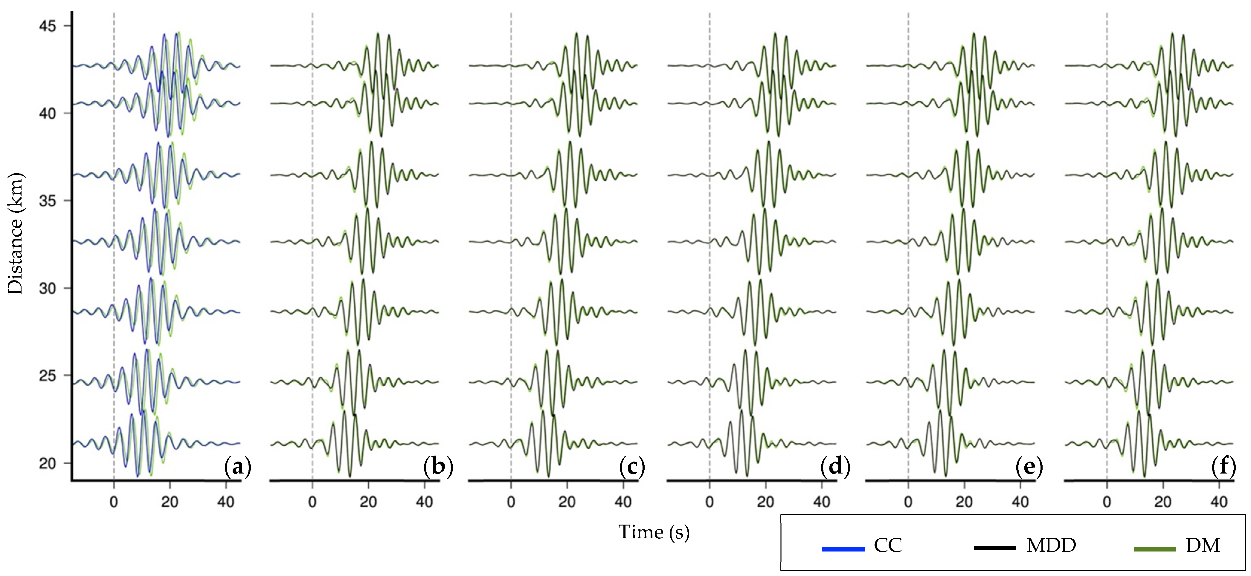
Figure 5a presents the SI by CC results for the TE stations (TE03–TE09) for a virtual source at TN08 in the frequency range of 0.2–0.3 Hz. We use Equation (1) to directly model the surface-wave responses, which we use for comparison with the CC results. For the application of SI by MDD, we apply SVD to individual discrete frequencies between 0.1 and 0.5 Hz with an increment of 0.0008 Hz. For each discrete frequency and following Equation (9), the column vector v A contains the observations of the 11 earthquakes at a TE station and the matrix V B   contains the earthquake observations at the TN stations (11 rows by 19 columns). Consequently, U is an 11 × 11 matrix, V is a 19 × 19 matrix, and we have 11 singular values, which are sorted in order of decreasing value. The threshold S introduced in Section 2 determines the number of singular values (the rank) that will be used to construct the Moore-Penrose pseudoinverse V B + . This may vary between frequencies. We set S to 85, 90, 95, 97, and 99 and evaluate the stability of the retrieved MDD responses for each of these thresholds. For instance, a threshold of 97 indicates that g d ( est ) can be reconstructed by using 97% of the energy.
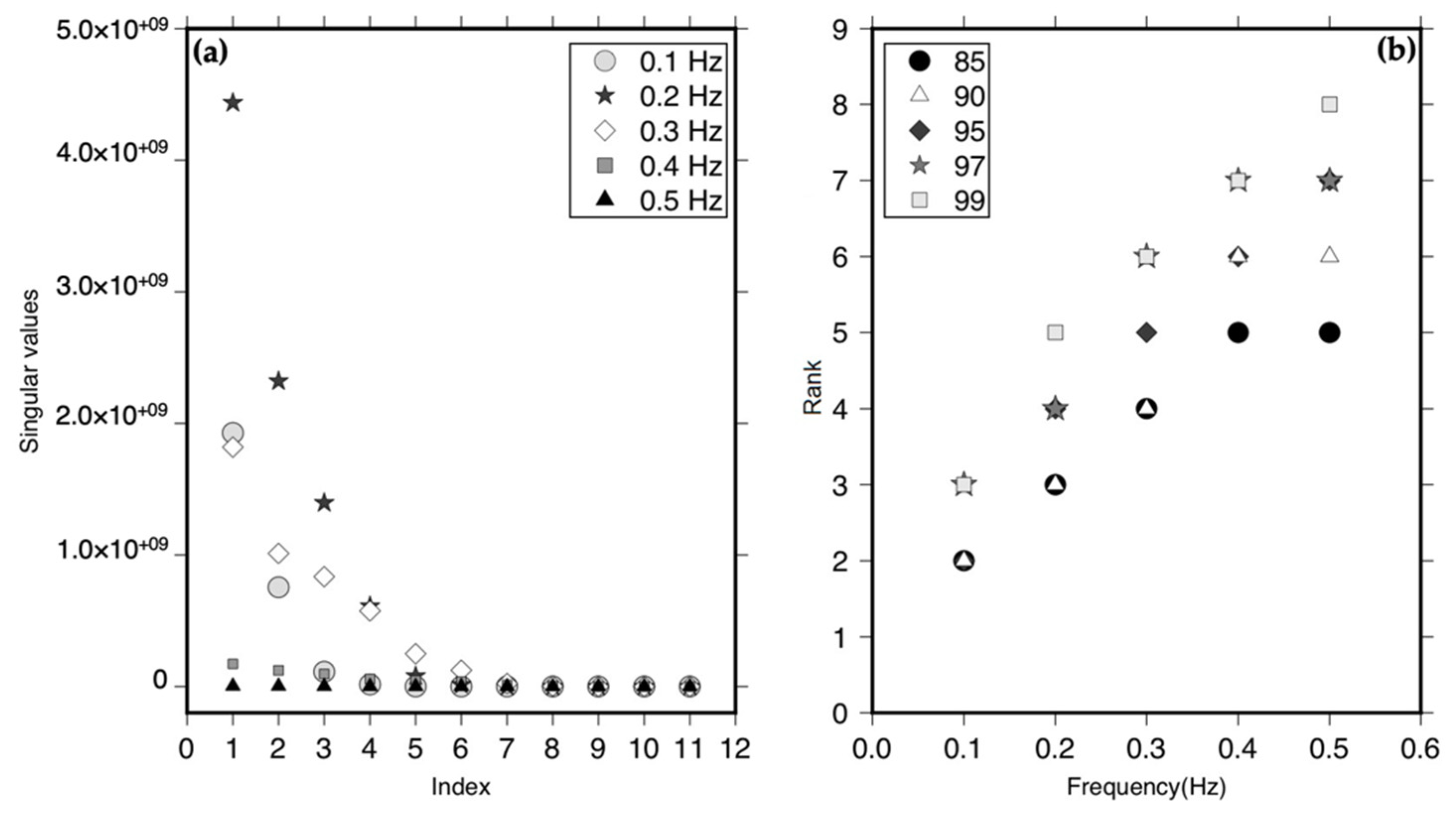
Figure 6a shows the different singular values for individual frequencies, while Figure 6b shows the rank associated with the different thresholds for the individual frequencies. In these figures, we show only the results for the discrete frequencies 0.1 Hz, 0.2 Hz, 0.3 Hz, 0.4 Hz, and 0.5 Hz, but the procedure is, of course, applied to all discrete frequencies in the range of 0.1–0.5 Hz.
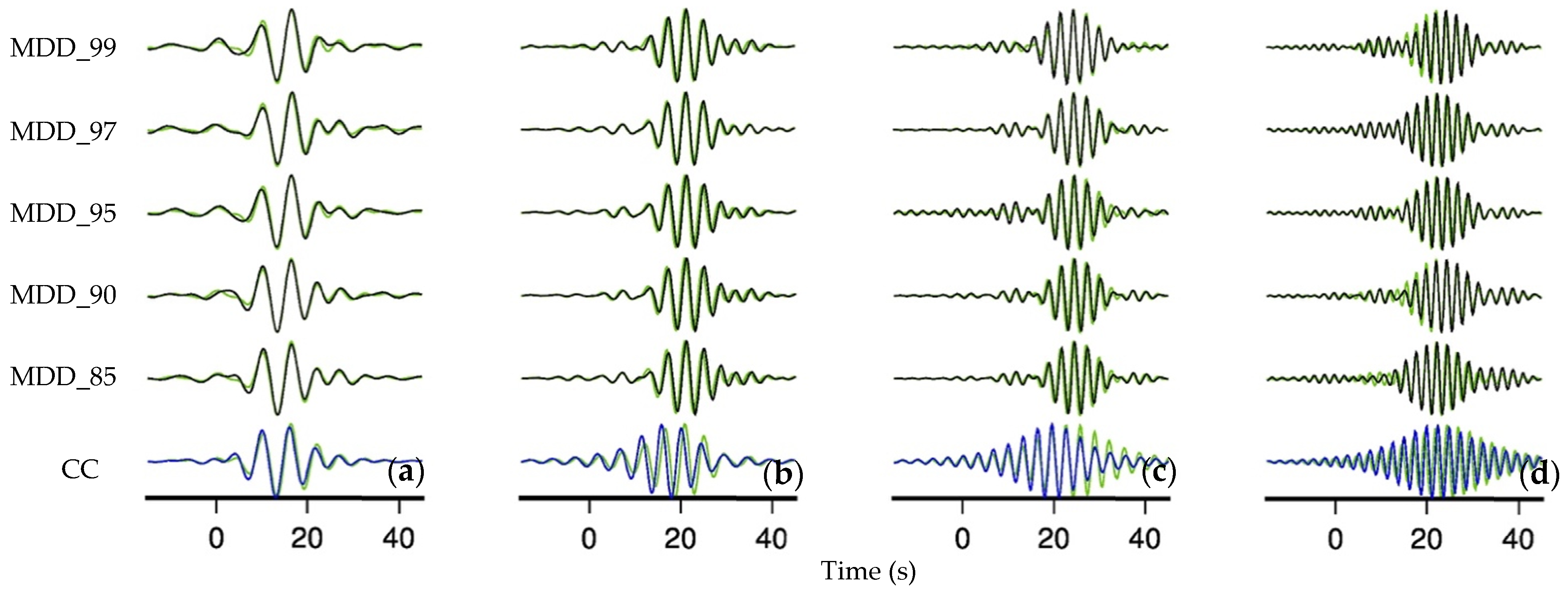
We apply SVD, using different thresholds, for all receivers between TE03 and TE09, while the stations along the TN line act as virtual sources. Figure 5b–f show the responses of SI by MDD for the TE stations for a virtual source at TN08 in the frequency range of 0.2–0.3 Hz for each of the tested thresholds. In Figure 7, we compare the CC and MDD responses to the directly modelled response at TE07 for (virtual) source at TN08 in the different frequency ranges between 0.1 Hz and 0.5 Hz.
Overall, the results in Figure 5 indicate that for the different receiver pairs, the MDD responses are more accurate than the CC responses and that there is a relatively small difference between MDD responses associated with different thresholds. The results in Figure 7 indicate that the accuracy of the MDD responses is higher than that of the CC responses in the different frequency ranges for the TE07–TN08 pair. We also observe this for other virtual-source receiver pairs.
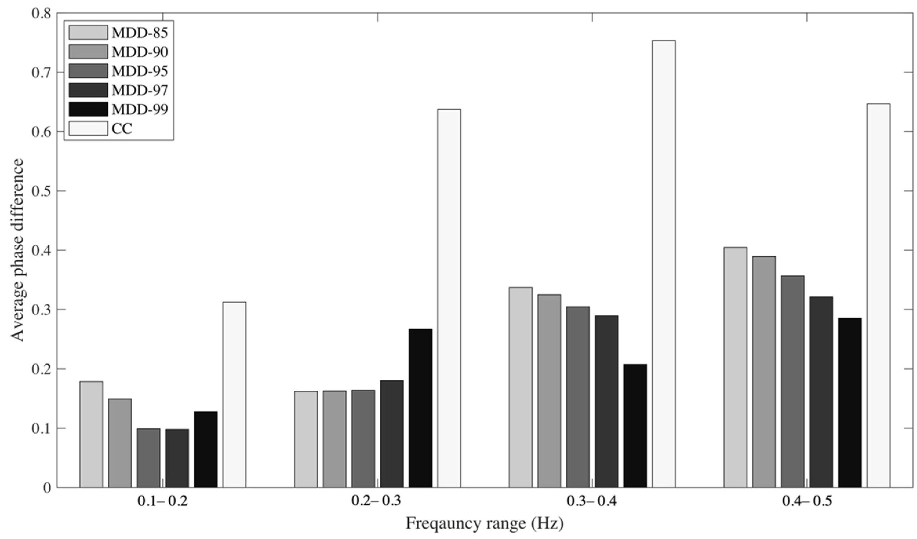
We quantify the accuracy of the phase of the retrieved virtual-source responses by computing the phase difference between the SI results and the directly modelled responses. Figure 8 shows the average absolute phase difference for four different frequency bands for responses retrieved at TE03–TE09 from virtual sources at stations TN06-TN16. Virtual sources at TN stations TN02-TN05 and TN17-TN20 are excluded because their responses are affected by the truncation of Srec (see Equation (5)). The comparison demonstrates that the phase of the responses retrieved through SI by CC deviates more from the phase of the true (directly modelled) responses than the phase of the responses retrieved through SI by MDD. This is the case for all frequency ranges and all thresholds, which is in line with the larger travel-time deviations of the CC responses (compared to the travel-time deviations of the MDD responses) observed in Figure 5 and Figure 7. We do not observe large variations in the phase difference between the directly modelled response and the MDD responses associated with different thresholds.
In order to test the stability of the phase and amplitude of retrieved responses of SI by CC and SI by MDD, we employ a bootstrapping method [41], which is a resampling technique used to calculate sample estimates by random sampling with replacement. It is based on resampling a sample population of fixed size, creating multiple realizations. We apply the bootstrapping principle to our set of 11 earthquakes in order to evaluate the stability of the retrieved interferometric responses. A single realization may contain an earthquake of the original dataset more than once but may not contain some of the other earthquakes at all. Specifically, the number of earthquakes in each of the 100 realizations coincide with that of the original data set [42], i.e., 11. Interferometric response retrieval is applied to each of the realizations individually, allowing us to evaluate the stability of the phase and amplitude of the retrieved responses.
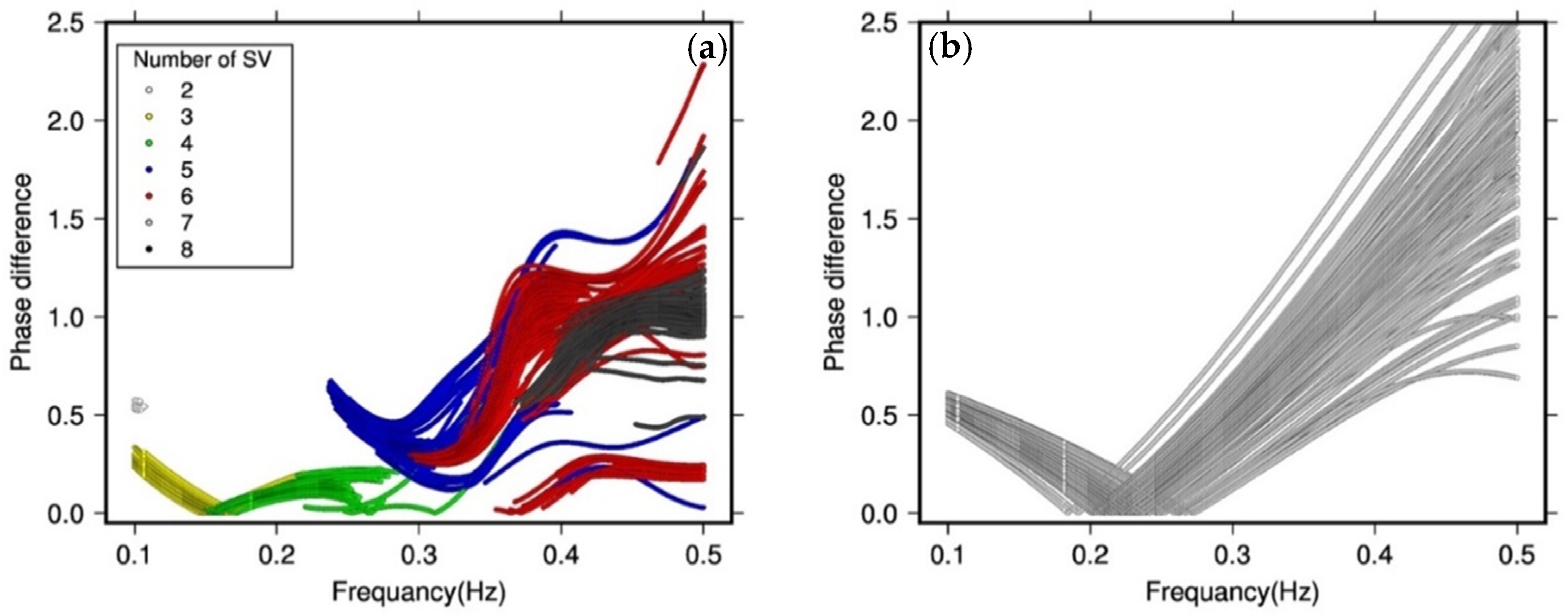
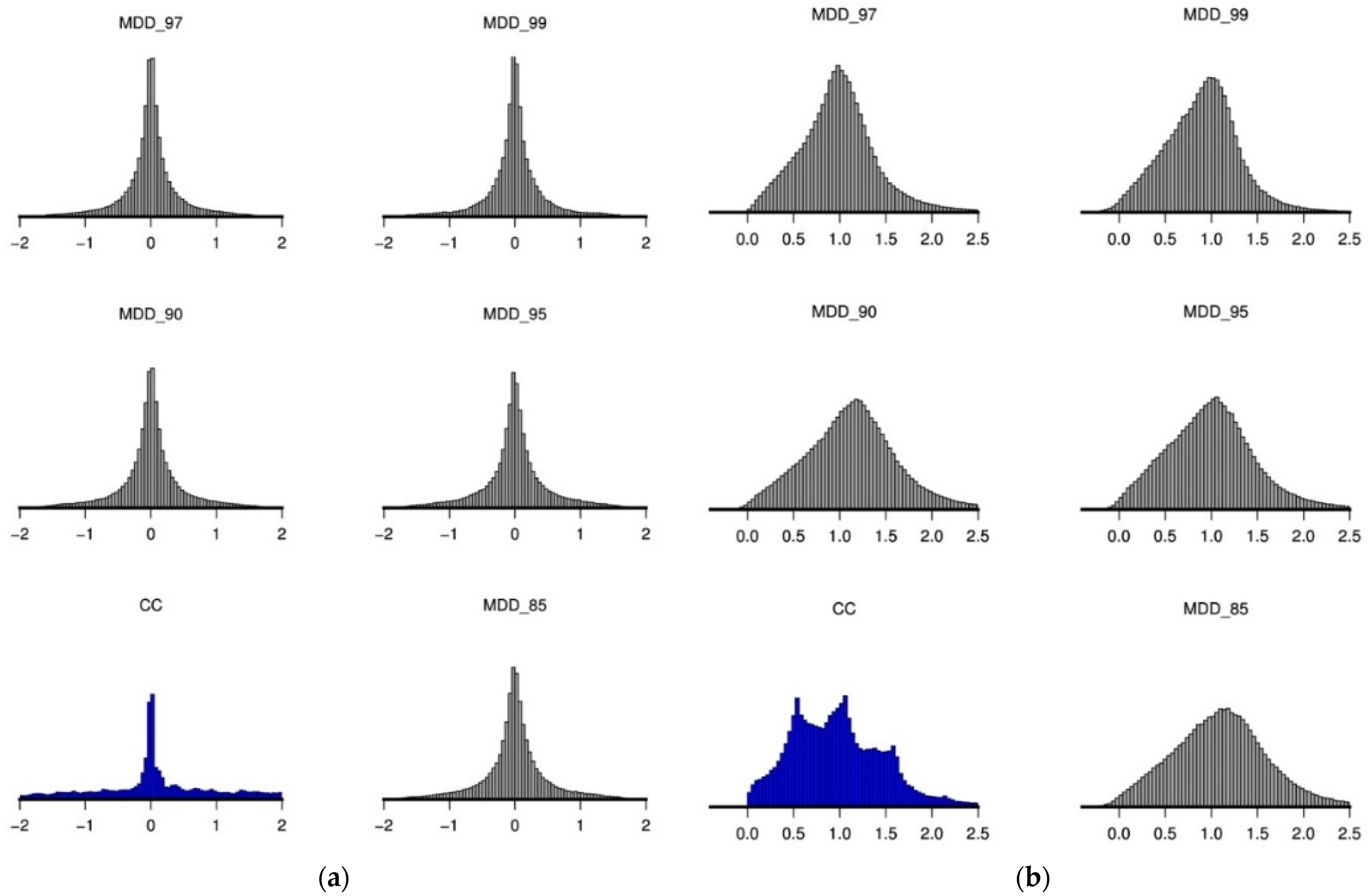
The phase and amplitude of the responses retrieved using SI by MDD with threshold 97 yields the most stable responses. We can see this in Figure 9, which shows, in the time domain, 100 superimposed responses from a virtual source at TN11 in the frequency range of 0.1–0.2 Hz. The response is retrieved at TE07 using SI by CC and SI by MDD with different thresholds. Focussing on the phase of the retrieved responses, we calculate the absolute value of the phase difference between the directly modelled response and the responses retrieved using SI by MDD with threshold 97 and using SI by CC (after having unwrapped the phases). Figure 10 shows that the variation in phase is lower for the responses retrieved using SI by MDD. In particular, this is the case for frequencies between 0.1 and 0.25 Hz, the frequency range containing most energy. Above 0.25 Hz, the variation in phase is complicated by varying numbers of singular values for different realizations.
To draw firmer conclusions, we investigate the stability of the phase and amplitude with respect to their mean for all virtual sources. In Figure 11, we systematically compare the magnitude of the variations in the phase and amplitude between the different methods. The phases and amplitudes of the responses from virtual sources TN06-TN16 between 0.1 Hz and 0.5 Hz are used. We infer from Figure 11 that the variation in the amplitude and phase of the MDD responses is significantly lower compared to that of the CC responses. We conclude from Figure 11 that the application of SI by MDD improves the stability of the responses obtained by SI by CC, particularly for the amplitude. We observe the most significant improvement in the MDD responses (phase and amplitude) with the threshold set to 97, which results in the narrowest distribution.

4.2. The Effect of Site Amplification

We investigate the stability of the interferometric responses retrieved using SI by CC and SI by MDD in the context of local site amplification. For that purpose, we prescribe a different (relative) amplification for the recordings by the different TN stations. That is, the generated synthetic earthquake recordings are multiplied with a different amplification factor (solid red circles in Figure 12b).
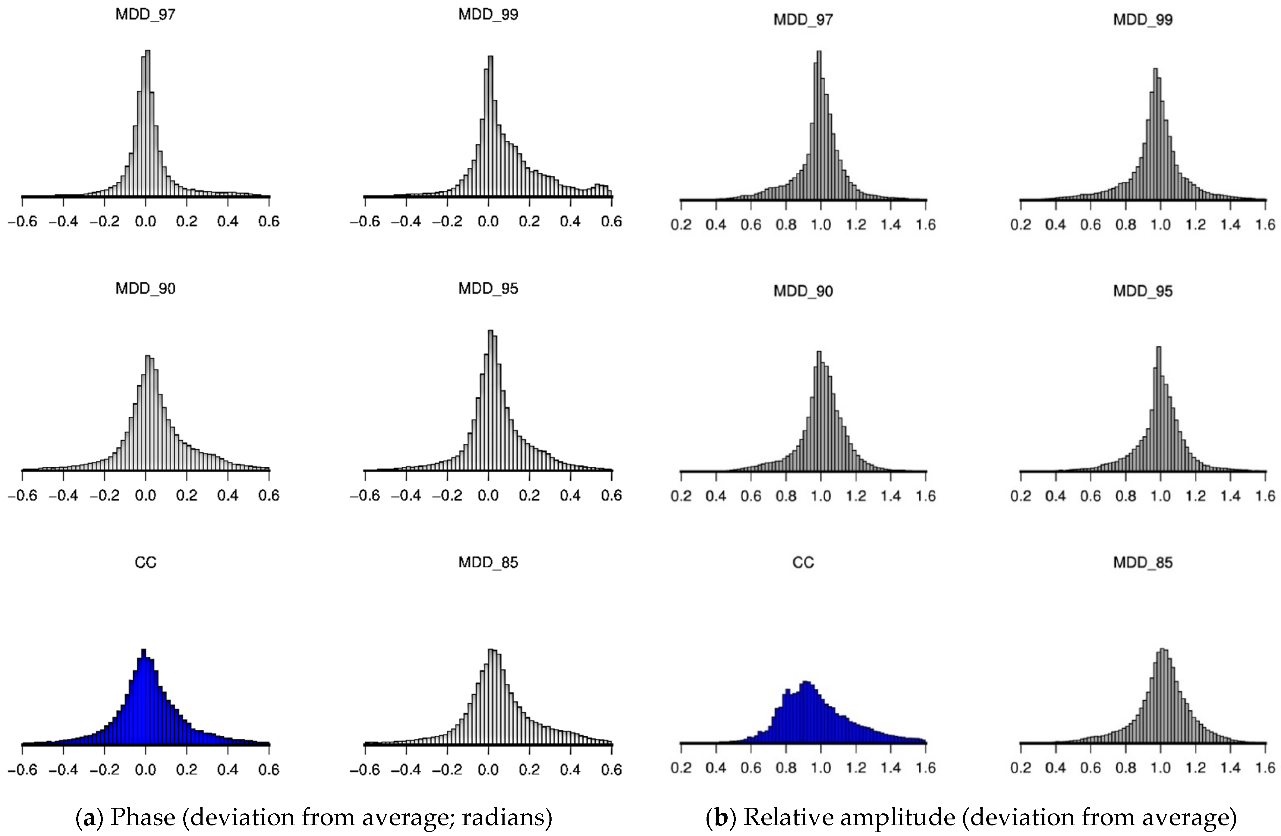
To evaluate the stability of the phase and amplitude of the responses retrieved through SI by CC and SI by MDD, we perform bootstrapping in the same way as explained above. Figure 13 shows the distributions of the phase and amplitude of the responses retrieved at station TE07 with respect to their mean values for SI by CC and SI by MDD with different thresholds in the frequency range of 0.1–0.5 Hz. We can see that in the presence of site amplification, the MDD responses show improvement with respect to the CC responses, especially for the results retrieved using thresholds of 95 and 97.
Figure 12 compares the relative amplitudes of responses at TE07 from virtual sources at TN06–TN16 retrieved through SI by CC and SI by MDD. The threshold is set to 97, and the considered frequency range is 0.2–0.3 Hz. Again, 100 realizations are generated. Relative amplitudes of the responses retrieved in the absence of site amplification (setup of Section 4.1) are shown in Figure 12a, whereas relative amplitudes of the responses retrieved in the presence of site amplification are shown in Figure 12b. We normalize all amplitudes with respect to the mean amplitude of the responses between 0.2 and 0.3 Hz from virtual sources at TN05–TN07, which have a prescribed site amplification of one. As we can see in Figure 12, in the absence of site amplification, the relative amplitudes of the retrieved CC responses and the retrieved MDD responses are close to one, and the retrieved MDD responses are more stable (Figure 12a). In the presence of site amplification, the relative amplitude of the retrieved CC responses simply increases with the prescribed site amplification (solid red circles in Figure 12b). The pattern is more complicated for the retrieved MDD responses, where we have computed the inverse of the retrieved amplitudes for the purpose of a fair comparison (see. Equation (5)). The singular value decomposition partly removes the effect of the site amplification, but some of the effect remains.

4.3. Application to Field Data from Earthquake-Generated Surface Waves

In this subsection, we showcase the application of SI by MDD to the earthquake data recorded by MalARRgüe. We compare these results to the responses retrieved through SI by CC applied to the same recordings. First, for each earthquake, we separate the surface-wave recording. We do this by determining the surface-wave window and use this to extract the surface-wave arrivals. The window has a cosine taper of 5% at both ends. Figure 14 presents the extracted surface-wave arrivals at station TE07 for the 11 selected earthquakes.
Similar to the previous subsections, we perform bootstrapping to evaluate the stability of the phase and amplitude of the responses retrieved through SI by CC and SI by MDD. Figure 15 shows the distributions of the phase and amplitude of the responses at station TE07 with respect to their mean values as retrieved through SI by CC and through SI by MDD with different thresholds in the frequency range of 0.1–0.5 Hz. As we can see in the figure, SI by MDD shows a relatively smooth and narrow distribution in comparison with SI by CC; this applies in particular for the amplitudes of the retrieved responses. We can also see that, while for the phase deviation, there is no significant change between the different MDD thresholds, the amplitude distributions associated with thresholds 97 and 99 appear the narrowest (with the result for threshold 97 having a more pronounced peak around the mean). Even though the MDD results do show improvement over the CC results, the difference is not as large as for the synthetic tests. This could mean that the requirement of having one-sided illumination (not having back-scattered arrivals impinging on the TE stations from the east) is not met sufficiently. In addition, some reflected body-wave energy can be expected to be present in the windowed surface-wave responses. As we mention above, this is something that can be expected for the subsurface of the Malargüe region. Figure 16 shows, as an example, the comparison of the virtual-source responses retrieved through SI by CC and through SI by MDD with a threshold of 97 in the frequency range of 0.1–0.2 Hz for receivers at stations TE03–TE09 for a virtual source at TN06 and at TN08.

5. Conclusions

We applied seismic interferometry (SI) by multidimensional deconvolution (MDD) for the purpose of retrieving surface-wave responses to field data and synthetic earthquake responses, for which we assumed a laterally homogeneous model, in conjunction with the earthquake epicentres, forms the field data. Using the synthetic data, we also investigated the retrieval of surface waves in the presence of site amplification. We find that the application of SI by MDD results in surface-wave responses that are more accurate than the responses retrieved through SI by crosscorrelation (CC). In addition, we show that potential site amplification at the location of the virtual sources is partly mitigated by means of SI by MDD.
For the inversion implicit in SI by MDD, we employed singular value decomposition (SVD). For this technique, we investigated a range of different thresholds. We find that it is very important to determine the proper threshold for SVD and that this threshold may be different for different frequencies because of the limited number of earthquakes.
For the field data, we showed that SI by MDD provides a slight improvement in the retrieved responses in comparison with SI by CC. The fact that the improvement is limited is likely due to the laterally heterogenous subsurface of the Malargüe region, where the data were recorded, which adversely affects the applicability of SI by MDD. As shown by the synthetic tests, we expect to have a more pronounced improvement if the subsurface is relatively laterally homogeneous.
In general, our results suggest that SI by MDD suffers less than SI by CC from irregularities in the source distribution, one-sided illumination, and differences in the power spectra between the different sources. Our study offers a good insight into the applicability of SI by MDD to surface-wave responses from earthquakes and is the first of its kind (to our knowledge, SI by MDD has not been applied to earthquake surface waves).

Author Contributions

All authors contributed to the conceptualization, methodology, software, validation, and writing. All authors have read and agreed to the published version of the manuscript.

Funding

This research received no external funding.

Institutional Review Board Statement

Not Applicable.

Informed Consent Statement

Not Applicable.

Data Availability Statement

The earthquake data can be downloaded from Incorporated Research Institutions for Seismology (IRIS).

Acknowledgments

Figures were generated with the help of Generic Mapping Tools [43].

Conflicts of Interest

The authors declare no conflict of interest.

References

  1. Shapiro, N.M.; Campillo, M. Emergence of broadband Rayleigh waves from correlations of the ambient seismic noise. Geophys. Res. Lett. 2004, 31. [Google Scholar] [CrossRef] [Green Version]
  2. Wapenaar, K.; Fokkema, J. Green’s function representations for seismic interferometry. Geophysics 2006, 71, SI33–SI46. [Google Scholar] [CrossRef]
  3. Campillo, M.; Paul, A. Long-Range Correlations in the Diffuse Seismic Coda. Science 2003, 299, 547–549. [Google Scholar] [CrossRef] [PubMed] [Green Version]
  4. Roux, P.; Sabra, K.G.; Gerstoft, P.; Kuperman, W.A.; Fehler, M.C. P-waves from cross-correlation of seismic noise. Geophys. Res. Lett. 2005, 32. [Google Scholar] [CrossRef] [Green Version]
  5. Draganov, D.; Campman, X.; Thorbecke, J.; Verdel, A.; Wapenaar, K. Reflection images from ambient seismic noise. Geophysics 2009, 74, A63–A67. [Google Scholar] [CrossRef] [Green Version]
  6. Weemstra, C.; Draganov, D.; Ruigrok, E.; Hunziker, J.; Gomez, M.; Wapenaar, K. Application of seismic interferometry by multidimensional deconvolution to ambient seismic noise recorded in Malargüe, Argentina. Geophys. J. Int. 2016, 208, 693–714. [Google Scholar] [CrossRef] [Green Version]
  7. Ruigrok, E.; Campman, X.; Draganov, D.; Wapenaar, K. High-resolution lithospheric imaging with seismic interferometry. Geophys. J. Int. 2010, 183, 339–357. [Google Scholar] [CrossRef] [Green Version]
  8. Bakulin, A.; Calvert, R. The virtual source method: Theory and case study. Geophysics 2006, 71, SI139–SI150. [Google Scholar] [CrossRef]
  9. Draganov, D.; Wapenaar, K.; Thorbecke, J.; Nishizawa, O. Retrieving reflection responses by crosscorrelating transmission responses from deterministic transient sources: Application to ultrasonic data. J. Acoust. Soc. Am. 2007, 122, EL172–EL178. [Google Scholar] [CrossRef] [Green Version]
  10. Lindner, F.; Weemstra, C.; Walter, F.; Hadziioannou, C. Towards monitoring the englacial fracture state using virtual-reflector seismology. Geophys. J. Int. 2018, 214, 825–844. [Google Scholar] [CrossRef]
  11. Louie, J. Faster, Better: Shear-Wave Velocity to 100 Meters Depth from Refraction Microtremor Arrays. Bull. Seism. Soc. Am. 2001, 91, 347–364. [Google Scholar] [CrossRef]
  12. Chávez-García, F.J.; Luzón, F. On the correlation of seismic microtremors. J. Geophys. Res. Space Phys. 2005, 110, 11. [Google Scholar] [CrossRef] [Green Version]
  13. Zhang, X.; Hansteen, F.; Curtis, A.; De Ridder, S. 1-D, 2-D, and 3-D Monte Carlo Ambient Noise Tomography Using a Dense Passive Seismic Array Installed on the North Sea Seabed. J. Geophys. Res. Solid Earth 2020, 125, e2019JB018552. [Google Scholar] [CrossRef]
  14. Bommer, J.J.; Dost, B.; Edwards, B.; Kruiver, P.P.; Ntinalexis, M.; Rodriguez-Marek, A.; Stafford, P.J.; van Elk, J. Developing a model for the prediction of ground motions due to earthquakes in the Groningen gas field. Neth. J. Geosci. 2017, 96, s203–s213. [Google Scholar] [CrossRef] [Green Version]
  15. Olsen, K.B.; Akinci, A.; Rovelli, A.; Marra, F.; Malagnini, L. 3D Ground-Motion Estimation in Rome, Italy. Bull. Seism. Soc. Am. 2006, 96, 133–146. [Google Scholar] [CrossRef]
  16. Wapenaar, K.; van der Neut, J.; Ruigrok, E.; Draganov, D.; Hunziker, J.; Slob, E.; Thorbecke, J.; Snieder, R. Seismic interfer-ometry by crosscorrelation and by multidimensional deconvolution: A systematic comparison. Geophys. J. Int. 2011, 185, 1335–1364. [Google Scholar] [CrossRef] [Green Version]
  17. Slob, E.; Wapenaar, K. Electromagnetic Green’s functions retrieval by cross-correlation and cross-convolution in media with losses. Geophys. Res. Lett. 2007, 34. [Google Scholar] [CrossRef] [Green Version]
  18. Slob, E.; Draganov, D.; Wapenaar, K. Interferometric electromagnetic Green’s functions representations using propagation invariants. Geophys. J. Int. 2007, 169, 60–80. [Google Scholar] [CrossRef] [Green Version]
  19. Vasconcelos, I.; Snieder, R. Interferometry by deconvolution: Part 2—Theory for elastic waves and application to drill-bit seismic imaging. Geophysics 2008, 73, S129–S141. [Google Scholar] [CrossRef]
  20. Wapenaar, K.; Van Der Neut, J.; Ruigrok, E. Passive seismic interferometry by multidimensional deconvolution. Geophysics 2008, 73, A51–A56. [Google Scholar] [CrossRef] [Green Version]
  21. Wapenaar, K.; van der Neut, J. A representation for Green’s function retrieval by multidimensional deconvolution. J. Acoust. Soc. Am. 2010, 128, EL366–EL371. [Google Scholar] [CrossRef] [PubMed] [Green Version]
  22. Minato, S.; Matsuoka, T.; Tsuji, T.; Draganov, D.; Hunziker, J.; Wapenaar, K. Seismic interferometry using multidimensional deconvolution and crosscorrelation for crosswell seismic reflection data without borehole sources. Geophysics 2011, 76, SA19–SA34. [Google Scholar] [CrossRef] [Green Version]
  23. van Dalen, K.N.; Wapenaar, K.; Halliday, D.F. Surface wave retrieval in layered media using seismic interferometry by mul-tidimensional deconvolution. Geophys. J. Int. 2013, 196, 230–242. [Google Scholar] [CrossRef] [Green Version]
  24. Hartstra, I.E.; Almagro Vidal, C.; Wapenaar, K. Full-field multidimensional deconvolution to retrieve body-wave reflections from sparse passive sources. Geoph. J. Int. 2017, 210, 609–620. [Google Scholar] [CrossRef] [Green Version]
  25. Draganov, D.; Hunziker, J.; Heller, K.; Gutkowski, K.; Marte, F. High-Resolution Ultrasonic Imaging of Artworks with Seismic Interferometry for Their Conservation and Restoration. Stud. Conserv. 2018, 63, 277–291. [Google Scholar] [CrossRef] [Green Version]
  26. Minato, S.; Matsuoka, T.; Tsuji, T. Singular-value decomposition analysis of source illumination in seismic interferometry by multidimensional deconvolution. Geophysics 2013, 78, Q25–Q34. [Google Scholar] [CrossRef] [Green Version]
  27. Ruigrok, E.; Draganov, D.; Gómez, M.; E Ruzzante, J.; Torres, D.F.; Pumarega, I.L.; Barbero, N.; Ramires, A.; Gañan, A.R.C.; van Wijk, K.; et al. Malargüe seismic array: Design and deployment of the temporary array. Eur. Phys. J. Plus 2012, 127, 126. [Google Scholar] [CrossRef]
  28. Nishitsuji, Y.; Ruigrok, E.; Gòmez, M.; Draganov, D. Global-phase H/V spectral ratio for imaging the basin in the Malargüe region, Argentina. Seism. Res. Lett. 2014, 8, 1004–1011. [Google Scholar] [CrossRef] [Green Version]
  29. Nishitsuji, Y.; Marin, L.E.F.; Gomez, M.; Rowe, C.; Draganov, D. Tectonic tremor characterized by principal-component analysis in the vicinity of central Chile and Argentina. J. South Am. Earth Sci. 2019, 94, 102178. [Google Scholar] [CrossRef]
  30. Nishitsuji, Y.; Ruigrok, E.; Gomez, M.; Wapenaar, K.; Draganov, D. Reflection imaging of aseismic zones of the Nazca slab by global-phase seismic interferometry. Interpretation 2016, 4, SJ1–SJ16. [Google Scholar] [CrossRef]
  31. Nishitsuji, Y.; Minato, S.; Boullenger, B.; Gòmez, M.; Wapenaar, K.; Draganov, D. Crustal-scale reflection imaging and inter-pretation by passive seismic interferometry using local earthquakes. Interpretation 2016, 4, SJ29–SJ53. [Google Scholar] [CrossRef]
  32. Casas, J.A.; Draganov, D.; Badi, G.A.; Manassero, M.C.; Olivera Craig, V.H.; Franco Marín, L.; Gómez, M.; Ruigrok, E. Seismic interferometry applied to fracture seismicity recorded at Planchón-Peteroa Volcanic Complex, Argentina-Chile. J. South Am. Earth Sci. 2019, 92, 134–144. [Google Scholar] [CrossRef] [Green Version]
  33. Casas, J.A.; Badi, G.A.; Franco, L.; Draganov, D. Seismic interferometry applied to regional and teleseismic events recorded at Planchón-Peteroa Volcanic Complex, Argentina-Chile. J. Volcanol. Geotherm. Res. 2020, 393, 106805. [Google Scholar] [CrossRef]
  34. Casas, J.A.; Mikesell, T.D.; Draganov, D.; Lepore, S.; Badi, G.A.; Franco, L.; Gomez, M. Shallow S-Wave Velocity Structure from Ambient Seismic Noise at Planchón-Peteroa Volcanic Complex, Argentina-Chile. Bull. Seism. Soc. Am. 2018, 108, 2183–2198. [Google Scholar]
  35. Aki, K.; Richards, P.G. Quantitative Seismology, 2nd ed.; University Science Books: Sausalito, CA, USA, 2002; p. 700. [Google Scholar]
  36. Weemstra, C.; Boschi, L.; Goertz, A.; Artman, B. Seismic attenuation from recordings of ambient noise. Geophysics 2013, 78, Q1–Q14. [Google Scholar] [CrossRef] [Green Version]
  37. Weemstra, C.; Wapenaar, K.; Dalen, K.N.V. Reflecting boundary conditions for interferometry by multidimensional decon-volution. J. Acoust. Soc. Am. 2017, 142, 2242–2257. [Google Scholar] [CrossRef] [PubMed]
  38. Wapenaar, K.; Ruigrok, E.; Van Der Neut, J.; Draganov, D. Improved surface-wave retrieval from ambient seismic noise by multi-dimensional deconvolution. Geophys. Res. Lett. 2011, 38. [Google Scholar] [CrossRef] [Green Version]
  39. Tsai, V.C. Understanding the amplitudes of noise correlation measurements. J. Geophys. Res. Space Phys. 2011, 116. [Google Scholar] [CrossRef] [Green Version]
  40. Paolucci, R.; Mazzieri, I.; Piunno, G.; Smerzini, C.; Vanini, M.; Özcebe, A. Earthquake ground motion modeling of induced seismicity in the Groningen gas field. Earthq. Eng. Struct. Dyn. 2021, 50, 135–154. [Google Scholar] [CrossRef]
  41. Efron, B. The Jackknife, the Bootstrap, and other Resampling Plans; Society for Industrial and Applied Mathematics: Philadelphia, PA, USA, 1982. [Google Scholar]
  42. Efron, B.; Tibshirani, R. An Introduction to the Bootstrap Method; Chapman and Hall: New York, NY, USA, 1993. [Google Scholar]
  43. Wessel, P.; Luis, J.F.; Uieda, L.; Scharroo, R.; Wobbe, F.; Smith, W.H.F.; Tian, D. The Generic Mapping Tools Version 6. Geochem. Geophys. Geosystems 2019, 20, 5556–5564. [Google Scholar] [CrossRef] [Green Version]
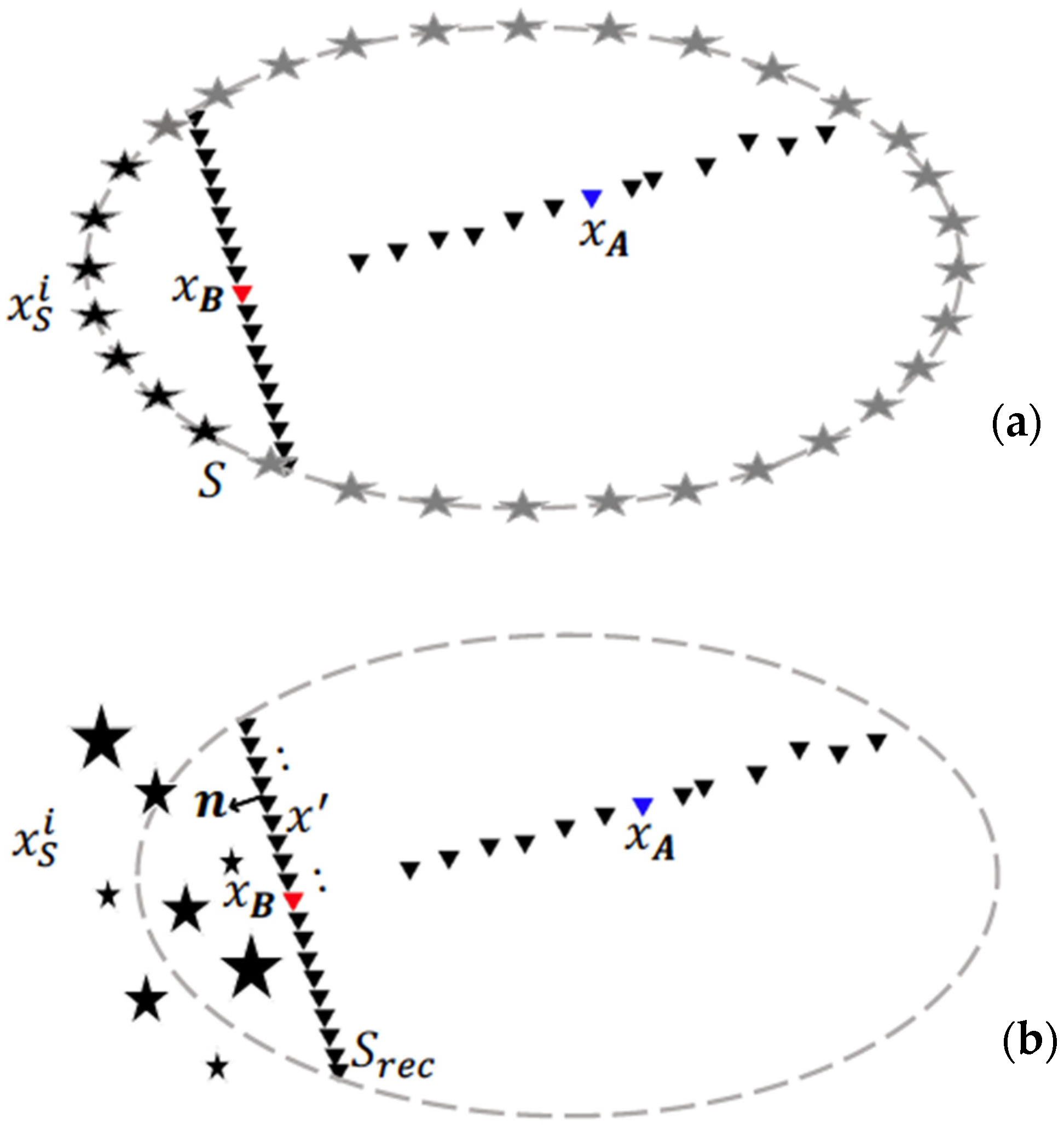
Figure 1. Source configuration associated with (a) SI by crosscorrelation (CC) and (b) SI by multidmensional deconvolution (MDD). Stars indicate sources. Triangles indicate receivers. For successful application of SI by CC, the sources (black and grey stars in (a)) need to be characterised by the same source-time function and be regularly distributed along a boundary in the far field of the receivers; successful application of SI by MDD does not require this, and hence, the sources can be distributed randomly and have different source-time functions (illustrated by varying sizes of the stars in (b). The red triangle depicts the position of a (possible) virtual source along the north-south oriented line of receivers, whereas the blue triangle indicates the position of a receiver along the east-west oriented line of receivers.
Remotesensing 13 04818 g001
Figure 2. (a) Location of MalARRgüe and location and magnitude of the earthquakes generating surface waves used in this study. (b) Configuration of the T-array of MalARRgüe, with the triangles presenting the station locations.
Remotesensing 13 04818 g002
Figure 3. Recordings of the 11 earthquakes (Table 1) by station TE07. Traces are sorted according to the distance between an earthquake’s epicentre and TE07. The recordings are bandpass filtered between 0.1 Hz and 0.5 Hz. The numbers next to the traces correspond to the numbers (1–11) in Table 1).
Remotesensing 13 04818 g003
Figure 4. (a) Surface-wave phase velocity of the modelled surface waves as a function of frequency. (b) Amplitude spectrum of the sources used in our modelling.
Remotesensing 13 04818 g004
Figure 5. (a) Virtual-source responses at stations TE03–TE09 obtained from SI by CC (blue colour) for a virtual source at station TN08 in the frequency range of 0.2–0.3 Hz. (b) Responses retrieved by means of SI by MDD (black colour), filtered between 0.2 and 0.3 Hz, for a threshold of 85. (cf) Same as (b) but for a threshold of 90, 95, 97, and 99, respectively. The green colour indicates directly modelled (DM) responses.
Remotesensing 13 04818 g005
Figure 6. (a) The singular values for individual frequencies. (b) Rank associated with the five different thresholds for the frequencies in (a).
Remotesensing 13 04818 g006
Figure 7. Comparison between the directly modelled response (green) and the retrieved responses using SI by CC (blue colour) and SI by MDD (black colour) at station TE07 from a virtual source at station TN08 in the frequency range of (a) 0.1–0.2 Hz, (b) 0.2–0.3 Hz, (c) 0.3–0.4 Hz, and (d) 0.4–0.5 Hz.
Remotesensing 13 04818 g007
Figure 8. The average absolute phase difference between the directly modelled responses and the SI responses for virtual sources at stations TN06–TN16 (after having unwrapped the phases). The responses to these virtual sources are retrieved at stations TE03–TE09. We have differentiated between SI by CC (white) and SI by MDD (grey to black) for the different thresholds (85, 90, 95, 97, 99). Averages over the various virtual sources, receivers, and discrete frequencies are computed independently for the different frequency ranges.
Remotesensing 13 04818 g008
Figure 9. Comparison of the responses retrieved using different methods (SI by CC and SI by MDD for different thresholds) for all realizations from bootstrapping. The responses are retrieved at station TE07 from a virtual source at station TN11 and filtered between 0.1 and 0.2 Hz.
Remotesensing 13 04818 g009
Figure 10. The absolute values of the phase difference between the directly modelled responses and the interferometric response at TE07 for a virtual source at TN11 for all frequency ranges and all realizations of the bootstrapping method: (a) SI by MDD with a threshold of 97 (different colours are associated with different ranks); (b) SI by CC.
Remotesensing 13 04818 g010
Figure 11. Distributions of the (a) phase and (b) amplitude of the retrieved responses with respect to their mean values for SI by CC (blue histogram) and SI by MDD with different thresholds (grey histograms) for all realizations. Distributions are computed from all virtual-source responses at station TE07 between 0.1 Hz and 0.5 Hz. The amplitudes of the responses are normalized with respect to the mean amplitude for each frequency, virtual source-receiver pair, and method individually.
Remotesensing 13 04818 g011
Figure 12. Relative amplitude of the responses retrieved at TE07 from virtual sources at TN06-TN16 in the frequency range of 0.2–0.3 Hz and for all realizations of the bootstrapping method using SI by CC (blue lines) and SI by MDD with threshold 97 (black lines) (a) in the absence of site amplification; and (b) in the presence of site amplification. All amplitudes are normalized with respect to the mean amplitude of the responses from virtual sources TN05–TN07. Red circles show site amplification prescribed for the different TN stations.
Remotesensing 13 04818 g012
Figure 13. As in Figure 11 but in the presence of site amplification. (a) Phase (deviation from average; radians). (b) Relative amplitude (deviation from average).
Remotesensing 13 04818 g013
Figure 14. Surface-wave arrivals at station TE07 for the chosen 11 earthquakes (compare with Figure 3). Traces are sorted according to the distance between an earthquake’s epicentre and TE07. The recordings are bandpass filtered between 0.1 Hz and 0.5 Hz.
Remotesensing 13 04818 g014
Figure 15. As in Figure 11 but for the field data. (a) Phase (deviation from average; radians). (b) Relative amplitude (deviation from average).
Remotesensing 13 04818 g015
Figure 16. (a) Virtual-source responses at stations TE03–TE09 for a virtual source at station TN06 obtained from SI by CC (blue colour) and SI by MDD for a threshold of 97 (black colour) for application of field data in the frequency range of 0.1–0.2 Hz and (b) same as (a) but for a virtual source at TN08.
Remotesensing 13 04818 g016
Table 1. Epicentres and magnitudes of the earthquakes from Figure 2a, the direct surface waves of which are used for interferometric surface-wave retrieval.
Num.Longitude (DD)Latitude (DD)Magnitude ScaleMagnitude
1−73.981−38.148MW4.5
2−74.237−37.455ML4.1
3−73.723−37.658MB4.5
4−73.547−37.654ML4.2
5−73.397−37.199MB5.0
6−72.985−37.512MB4.8
7−73.462−35.776MB4.8
8−72.766−35.541MB4.3
9−72.012−35.127MB4.7
10−71.075−36.036MB5.0
11−70.570−36.074MW6.0
Publisher’s Note: MDPI stays neutral with regard to jurisdictional claims in published maps and institutional affiliations.