Article

A High-Speed, Light-Weight Scalar Magnetometer Bird for km Scale UAV Magnetic Surveying: On Sensor Choice, Bird Design, and Quality of Output Data

by
Arne Døssing
1,2,*,
Eduardo Lima Simoes da Silva
1,2,
Guillaume Martelet
3,
Thorkild Maack Rasmussen
4,
Eric Gloaguen
3,
Jacob Thejll Petersen
1 and
Johannes Linde
5
1
CMAGTRES, Geomagnetism, DTU Space, Technical University Denmark, Centrifugevej 356, 2850 Kgs. Lyngby, Denmark
2
DTU CERE, Technical University Denmark, 2850 Kgs. Lyngby, Denmark
3
Bureau de Recherches Géologiques et Minières (BRGM), 45060 Orléans, France
4
Department of Civil, Environmental and Natural Resources Engineering Luleå Technical University, 971 87 Luleå, Sweden
5
Geodesy and Earth Observation, DTU Space, Elektrovej 328, 2850 Kgs. Lyngby, Denmark
*
Author to whom correspondence should be addressed.
Remote Sens. 2021, 13(4), 649; https://doi.org/10.3390/rs13040649
Submission received: 13 January 2021 / Revised: 6 February 2021 / Accepted: 8 February 2021 / Published: 11 February 2021
(This article belongs to the Section Remote Sensing in Geology, Geomorphology and Hydrology)

Abstract

:
Magnetic surveying is a widely used and cost-efficient remote sensing method for the detection of subsurface structures at all scales. Traditionally, magnetic surveying has been conducted as ground or airborne surveys, which are cheap and provide large-scale consistent data coverage, respectively. However, ground surveys are often incomplete and slow, whereas airborne surveys suffer from being inflexible, expensive and characterized by a reduced signal-to-noise ratio, due to increased sensor-to-source distance. With the rise of reliable and affordable survey-grade Unmanned Aerial Vehicles (UAVs), and the developments of light-weight magnetometers, the shortcomings of traditional magnetic surveying systems may be bypassed by a carefully designed UAV-borne magnetometer system. Here, we present a study on the development and testing of a light-weight scalar field UAV-integrated magnetometer bird system (the CMAGTRES-S100). The idea behind the CMAGTRES-S100 is the need for a high-speed and flexible system that is easily transported in the field without a car, deployable in most terrain and weather conditions, and provides high-quality scalar data in an operationally efficient manner and at ranges comparable to sub-regional scale helicopter-borne magnetic surveys. We discuss various steps in the development, including (i) choice of sensor based on sensor specifications and sensor stability tests, (ii) design considerations of the bird, (iii) operational efficiency and flexibility and (iv) output data quality. The current CMAGTRES-S100 system weighs ∼5.9 kg (including the UAV) and has an optimal surveying speed of 50 km/h. The system was tested along a complex coastal setting in Brittany, France, targeting mafic dykes and fault contacts with magnetite infill and magnetite nuggets (skarns). A 2.0 × 0.3 km area was mapped with a 10 m line-spacing by four sub-surveys (due to regulatory restrictions). The sub-surveys were completed in 3.5 h, including >2 h for remobilisation and the safety clearance of the area. A noise-level of ±0.02 nT was obtained and several of the key geological structures were mapped by the system.

Graphical Abstract

1. Introduction

Getting reliable geophysical models of the subsurface is an absolute necessity for the successful mapping of raw materials resources, subsurface contamination, archaeology or Unexploded Ordnance (UXO). As compared to other geophysical measurements, such as seismic and gravity, magnetic measurements are relatively cheap and straightforward, and they provide a strong response to even small petrophysical variations in the subsurface. Hence, magnetic measurement campaigns are often an indispensable component in most subsurface mapping programmes [1,2,3,4,5,6].
Since being accepted as a cost-efficient subsurface mapping approach more than 50 years ago [7,8,9,10], magnetic measurements have been conducted mainly as ground (walking) magnetic surveys, that is, a person traversing an area of interest while carrying a magnetometer, or as airborne surveys in which a small airplane or helicopter carries a magnetometer system in various configurations. While ground magnetic surveys are typically cheap and offer a high signal-to-noise ratio (SNR), they are often time-consuming and incomplete (Figure 1). In contrast, airborne surveys provide a fast, regional-scale and consistent data coverage but suffer from a lower SNR due to the rapid fall-off of the crustal magnetic field with altitude. Airborne survey systems are typically also characterized by higher noise levels, in particular, for fixed-wing airborne survey systems in which magnetometers are affixed directly to the airplane frame (Figure 1).
The use of a magnetometer bird provides a means to increase the SNR in airborne surveys by decreasing the source-to-receiver distance and separating the magnetometer from the electromagnetic and magnetic noise of the aircraft. A magnetometer bird can take on various shapes and sizes but is often an elongated, aerodynamically shaped, shell that houses one or multiple magnetometers (“single sensor bird” vs. “gradiometer bird”). In the traditional setup, the magnetometer bird is towed 30–50 m below a helicopter, which can follow the topography to keep a fairly constant source-to-receiver distance and, thereby, generate close-to-consistent data quality throughout a survey (Figure 1). While providing state-of-the art data, heliborne magnetometer bird surveys are associated with high costs due to the need for fuel, skilled pilots and specialized equipment, i.e., heliborne surveys are not always economically viable in (remote) areas with, e.g., limited access to fuel, equipment and personnel. For safety reasons, helicopters also need to stay well clear from topography, i.e., a complete draping of the terrain in areas with steep topography is often not possible (Figure 1).

1.1. UAV Magnetic Survey Systems: Opportunities and Current State-of-the Art

With the increased reliability of survey-grade Unmanned Aerial Vehicles (UAVs), or simply drones, and the developments of light-weight magnetometers, opportunities arise for conducting high-quality km scale magnetic surveying in previously inaccessible areas, at significantly reduced costs, and with a much higher flexibility in the planning and operation phases [12,13,14,15,16,17]. Overall, a UAV magnetic survey system can be designed in three ways (disregarding fixed-wing systems): (i) a fixed-boom setup using a boom affixed to the UAV frame, (ii) a towed sensor setup, or (iii) a towed magnetometer bird, as shown in Figure 2.
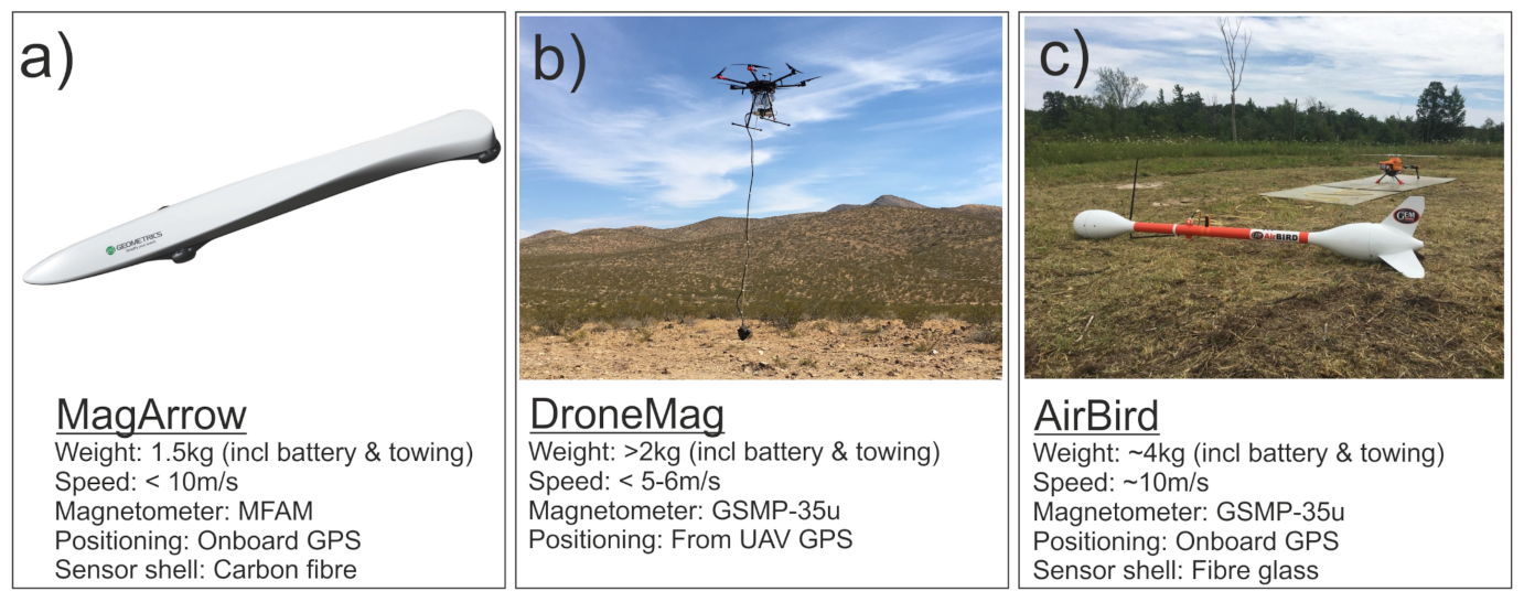
Various commercially available UAV magnetic survey systems exist on the market (Figure 3): The single-sensor AirBird of GemSystems and MagArrow of Geometrics; both systems that deploy a total-field (scalar) magnetometer in a bird configuration below some sort of multi-rotor UAV. As a light-weight commercial alternative, the DroneMag of GemSystems provides a towed (scalar) sensor setup; a solution also sought by [14] in deploying a GEM19-GW walking-mode magnetometer 3 m below a UAV. The AirBird (and its big brother: the double-sensor GradBird) systems weigh ∼4 kg and ∼7 kg, respectively, while the DroneMag and MagArrow weigh ∼1.5–2 kg, including battery and towing accessories. Hence, the AirBird and GradBird require a heavy-lifter UAV, which becomes impracticable if the study area cannot be accessed directly by car. On the other hand, the DroneMag is limited by its lack of aerodynamic stability and sensor stability at high speeds, while the MagArrow offers the lowest sensor quality (discussed below) as well as recommended speeds (for stability reasons) of less than 10 m/s. Relative fluxgate-type magnetic survey systems are offered, e.g., by the MagDrone R3 of Sensys, which may be defined as a fixed-boom setup Figure 2a. However, fluxgate sensors are (due to their lower sensitivity) typically used in setups where they are directly affixed to the UAV-frame via some sort of rod [18]. These are simple and light-weight setups, but with significantly higher noise levels, even for the post-processing results.

1.2. Pros and Cons of a Magnetometer Bird

A towed magnetometer bird setup provides a number of potential advantages (and disadvantages) as compared to the fixed-boom and towed sensor setups (Figure 2). If designed comprehensively, a magnetometer bird offers a high SNR and resolution due to a combination of decreased sensor-to-source separation and a reduced electromagnetic and magnetic noise from the UAV as well as other electronic parts. As discussed by [16,17], a 4–5 m minimum separation is desirable in order to minimize magnetic interference from a standard survey-grade multi-rotor UAV. The magnetometer bird also provides some protection of the sensor head, the sensor control box and the (often fragile) communication cable in between from impacts, rain and dust. Importantly, the bird delivers the aerodynamic stability of the sensor, and thus, a high degree of directional control at high speeds. That latter is a key parameter for optimum efficiency but also provides a disadvantage when surveying areas with strong relief areas, since an aerodynamically stabilized bird requires high horizontal speeds and, hence, may not always be able to follow topography. Finally, a bird offers the possibility of precisely positioning the magnetic readings if integrating a (GPS/GNSS/IMU) positioning system in the bird. This is typically not possible for systems such as a free-hanging magnetometer (e.g., the DroneMag) although GPS-integration has been tested by [14] on a solution comparable to the DroneMag. Critical to keep the noise-level to a minimum, however, is that the GPS/GNSS/IMU is well separated (preferably >1 m) from the magnetometer sensor head; a solution not provided by [14].

1.3. Objective of the Study

Here, we describe the development, testing and output data quality of a light-weight, high-speed, scalar field magnetometer bird intended for km-scale surveying by small-to-medium sized UAVs. Our focus has been on high flexibility in terms of efficient mapping, quick deployment and an “all areas are accessible” idea; the latter made possible by a very low weight of the combined UAV and bird system, which makes it easy to carry several kilometers, even in rough terrain. As such, the bird is intended to offer high SNR magnetic surveys at sub-regional scale in areas that are difficult to access by other means. In this study, we discuss our choice of sensor (based on sensor tests), the design of the bird (based on strict operational criteria) and the results of a test campaign carried out in Brittany, France. Finally, we discuss the pros and cons of the new survey system against the commercially available state-of-the art systems in Figure 3.

2. Prototype Design and Specifications

2.1. Survey System Design Criteria

The magnetometer bird developed as part of this study is designed based on a number of operational criteria for the combined UAV and bird (hereafter collectively referred to as “survey system”). In particular, the survey system must:
  • Provide high-quality magnetic data at km scale for, e.g., mineral exploration purposes.
  • Be operationally efficient, i.e., the survey system should be fast to deploy and aerodynamically stable at UAV speeds of minimum 13–14 m/s (47–50 km/h) or even higher.
  • Be deployable in most terrain and weather conditions, i.e., (i) the operator must be able to easily carry the survey system several kilometers and deploy it, even in difficult terrain; (ii) the setup must be dust and water protected as well as operational in wind speeds of at least 8–10 m/s.
Based on the system design criteria, strict requirements were synthesized for the choice of UAV, magnetometer and the operational standards of the magnetometer bird (Table 1). A maximum weight of 6–7 kg is set for the survey system based on the criteria of high mobility in rough terrain. We, therefore, decided on a magnetometer bird that can be towed by a DJI M210 drone, which is a popular medium-sized quad-rotor UAV. The DJI M210 has a total weight of 4.7 kg, including two TB45 batteries, an IP-rating (water and dust protection) of 43, and a maximum payload capacity of 1.45 kg. The choice of a medium sized UAV to tow the magnetometer bird was motivated by the desire to keep the total weight of the survey system below 6–7 kg and, thereby, to maximize flexibility and versatility, to ease transportation and facilitate deployment in remote areas, and to be able to take-off and land in relatively confined spaces. We further decided to integrate a high performance optically-pumped (OP) scalar magnetometer in the bird as such sensors—as opposed to relative fluxgate magnetometers—provide fast and absolute magnetic field measurements and they are generally insensitive to rotation while the measurements are being made. OP magnetometers also deliver a high degree of long-term stability and are often superior in terms of sensitivity and accuracy. OP scalar magnetometers are, therefore, typically preferred over the fluxgate type magnetometers for high-quality airborne surveys [19,20]. With a desired surveying speed of 14 m/s, we require the OP magnetometer to provide a minimum sampling rate of 10–20 Hz, allowing one sample per minimum 0.7–1.4 m.

2.2. Choice of OP Magnetometer

2.2.1. General Magnetometer Evaluation Parameters

Weight and size of a magnetometer are two of the most critical parameters when designing a magnetometer bird system for an UAV. Given the limited payload capacity of typical survey-grade multi-rotor UAVs, the weight of a magnetometer bird should not exceed 60–80% of this capacity in order not to jeopardize flight stability by a heavy slung load effect or reduce the flight time significantly.
The sampling rate of the magnetometer is another critical parameter, as the sampling rate determines the minimum wavelength that can be properly sampled without aliasing the true signal at a given survey speed and altitude. Besides the sensor weight and sampling rate, one must also consider additional sensor specifications (often provided by the manufacturer) such as sensitivity, resolution, absolute accuracy, heading error, number and size(s) of dead zones, dynamic range, gradient tolerance, power consumption, operating temperatures, sensor head and sensor control box dimensions, as well as price. The sensitivity defines the smallest anomaly amplitude that can be detected by a magnetometer as a function of sampling rate. As such the sensitivity is a key proxy for the intrinsic instrument noise level or the instrument resolution, whichever is the largest. The absolute accuracy provides the difference between (average) readings of the magnetometer and the true field. In the case of magnetic surveying, the objective is to define true variations in the magnetic field throughout a survey region. For surveys where the magnetometer is kept turned on in between landings, the absolute error becomes less important, as long as it is consistent [21]. However, for km scale UAV surveys that require multiple days of operation or where re-mobilisation is needed to cover the area of interest, the absolute accuracy becomes important as a low accuracy will cause offsets between parts of the survey, even following the correction of diurnal variation. Likewise, the sensor drift, i.e., the change in the absolute error over time, is critical as a significant drift will cause unwanted artifacts to show up in the survey data [21].
The heading error and dead zone are key parameters that may severely limit the final data quality and the survey design process, respectively. A prominent heading error implies that the total field strength measured by the sensor changes with the orientation of the sensor [21]. Although such an error may be handled during the processing, the heading error is desirable to minimize in UAV magnetic surveying, where surveys are often defined as parallel survey lines flown in opposite directions. Additionally, it is highly desirable to minimize the number and size(s) of dead zone(s), which are orientation angles of operation where the signal is too weak for the instrument to output a reliable measurement. Dead zones, thus, provide limitations to the optimal direction of planned survey lines for a given area. Since the dead zones rely on the angle of the Earth’s magnetic field relative to the sensor, mitigation of the sensor dead zones changes with latitude.
Other parameters, which might be less quantitative—but yet critical—when designing a magnetometer bird, include the mechanical ruggedness of both the sensor head and control box, the available lengths and types of the connection cable between the sensor head and control box (e.g., flat/flex cable or standard) as well as the flexibility of the cable, i.e., is the cable flexible enough to be manipulated inside a narrow bird shell without being damaged? Finally, it is desirable to evaluate the sensor output data before choosing the best sensor, since small UAV-compatible magnetometers may suffer from reduced stability, as compared to standard airborne surveying sensors. Such an evaluation may help to reveal the true sensor stability in terms of outfalls, spikes, drift and general noise levels over multiple hours, which is critical for a successful sensor integration and end-product.

2.2.2. Evaluation of Pre-Selected of Magnetometers

Following a pre-screening of commercially available UAV-compatible OP scalar magnetometers, three OP magnetometers were purchased for further evaluation; all satisfying the weight and sampling rate criteria listed in Table 1: the Caesium Micro Fabricated Magnetometer (MFAM) from Geometrics, the Potassium GSMP-35u from GemSystems and the Rubidium QTFM from Quspin (Figure 4).
According to the specifications provided by the manufacturers (Table 2), the GSMP-35u has the lowest maximum sampling rate of 20 Hz as compared to 1000 and 400 Hz for the MFAM and QTFM, respectively. The GSMP-35u sampling rate may (in some cases) prevent true mapping of (very) short wavelength anomalies when flying at the desired speed of 14 m/s; a scenario to be expected if conducting, e.g., low-altitude mapping of UXO. In general, however, the GSMP-35u sampling rate is not a major disadvantage for most mapping purposes, albeit the high sampling rates of the MFAM and QTFM allow for the full mapping of anomalies, as well as any high-frequency external noise sources (e.g., 50 or 60 Hz from the power net). Such noise may then be properly filtered away during processing to obtain a more true signal. It is important to note, however, that the stated sampling rate of the QTFM is not fixed but fluctuates slightly around a prescribed mean rate, which makes it less trivial to analyze the output signal from the QTFM sensor.
According to Table 2, the GSMP-35u is superior in terms of sensitivity (0.3pT@1Hz/ 3pT@20Hz). The corresponding sensitivity for the MFAM and QTFM, respectively, are 7/ Hz 1/ Hz . The GSMP-35u is also superior in terms of absolute accuracy (±0.1 nT) and gradient tolerance (50,000 nT/m). The latter defines the ability of the magnetometer to obtain a true reading in a given gradient. This is particularly relevant for high-speed low-altitude UAV surveys, where strong gradients can be expected.
The GSMP-35u also provides the lowest heading error of ±0.05 nT, as compared to ±7.5 nT and ±1.5 nT of the MFAM and the QTFM, respectively (Table 2). Using a dual MFAM sensor setup (as recommended and done by Geometrics in the MagArrow bird; Figure 3), the combined heading error of the two MFAM sensors may be effectively reduced. To test this, we conducted an MFAM dual-sensor heading error test at the Brorfelde Geomagnetic Observatory (Denmark). A combined heading error of ±2 nT (peak-to-peak of 4 nT) was found (Figure S1, Supplementary Data). The reduced heading error is, however, only possible as long as both sensors are recording the field simultaneously outside their combined dead zones.
The GSMP-35u has two dead zones: a polar of ±10 and an equatorial of ±10 (Table 2). Even though the sizes of the GSMP-35u dead zones are small, the existence of two dead zones makes it less trivial to secure a correct angling of the sensor head while surveying. On the other hand, the MFAM has a single yet significant polar dead zone of ±35 . A way to mitigate this is, again, by surveying with a dual, oppositely configured, MFAM sensor setup. Of the three magnetometers, the QTFM has the smallest dead zone with a stated ±7 equatorial dead zone.

2.2.3. Magnetometer Drift and Reliability—Laboratory Tests

The operational stability and reliability of a sensor are not easily quantified in a table such as in Table 2. Three initial tests were, therefore, conducted of the MFAM and GSMP-35u at the Brorfelde Geomagnetic Observatory to characterize their performance with the specific aim to identify any behavioral issues such as instrument fall-outs, spiky behavior and drift. Test 1 and Test 2 were similar and involved the direct comparison of the MFAM and GSMP-35u against a Proton-precession GSM19 magnetometer and against the magnetic readings of the observatory. Test 3 concerned an evaluation of the two sensor head readings of a dual MFAM setup. In each test, the sensors to be tested were placed in the same magnetically quiet room and turned on at the same time. They were then allowed to run for about 1 h without any interference.
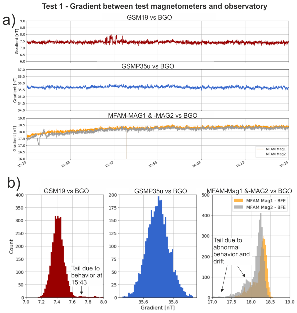
Background data of Test 1 (Figure S2, Supplementary Data) indicate that the GSM19, MFAM, and GSMP-35u magnetometers overall map a similar magnetic field during Test 1. However, a noisy behavior is observed of the GSM19 reference magnetometer around 15:43, and both sensors of the MFAM have multiple misreads (spikes) where the instruments measure incorrectly. By calculating the gradient between the sensor readings and the observatory readings, it is seen that both MFAM sensors display a prominent (up to 1 nT) drift over a period of 30 min following initialization (Figure 5a). It also becomes evident that MFAM-MAG2 shows abnormal behavior over a period of two minutes about five minutes after the test started. The gradient between the GSMP-35u and the observatory remains stable at around 35.75 nT, as does the gradient for the GSM19 at around 7.5 nT (disregarding the abnormal behavior around 15:43). Histograms of the calculated gradients can be used to check whether the noise of the sensors has a Gaussian distribution; that is, whether the noise can be regarded as randomly distributed with no underlying (bias) cause behind. A Gaussian distribution is found for both the GSMP-35u and the GSM19 gradients (Figure 5b), again disregarding the abnormal behavior at 15.43 for the GSM19, which adds a small right-sided tail to the histogram distribution. The corresponding histogram plots of the MFAM-MAG1 and MFAM-MAG2 sensors are skewed and—importantly—different. For the MFAM-MAG2, in particular, the histogram is associated with a marked top around 17.8 nT on the left flank of the plot, which is due to the abnormal behavior observed 3–4 min after the startup.
In order to validate Test 1, a similar test (Test 2) was carried out a few days later. The results (Figure S3, Supplementary Data) are comparable to the observations in Test 1, i.e., overall Test 1 and Test 2 indicate that the GSMP-35u provide stable readings, whereas the MFAM suffers from significant drift over a period of 30 min, as well as abnormal behavior within the first five minutes.
The MFAM drift and abnormal behavior was evaluated further in Test 3, which included the MFAM only. As shown in Figure S4, Supplementary Data, the drift is present in both MFAM sensors again but the drift does not seem to be consistent for the two sensors. The abnormal behaviour, observed five minutes after initialization in Test 1 and Test 2, is again present. This abnormal behavior appears most prominent in the MFAM-MAG2 sensor but with indications of a similar but less-amplitude behavior in the MFAM-MAG1.
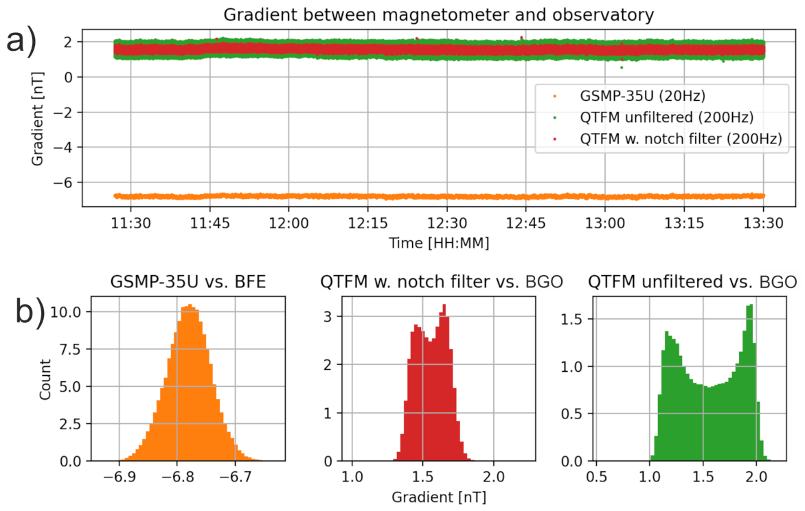
Following the stability tests of the MFAM and GSMP-35u, a two hours stability test (Test 4) was conducted on the QTFM against the observatory. A GSMP-35u was included in Test 4 for comparison purposes. The background data of Test 4 are shown in Figure S5, Supplementary Data, while the calculated gradient between the QTFM and the observatory readings are shown in Figure 6a. As seen, the QTFM is stable throughout the test period, albeit the QTFM displays a higher noise level, as compared to the GSMP-35u, even following a 50Hz notch filter to remove power line noise. The increased noise level was expected, given the technical specifications listed in Table 2. Importantly, we observe no indications of drift, abnormal behavior or spikes for the QTFM. This is also apparent in the gradient histogram plot of the QTFM Figure 6b, which appears overall symmetric. A double-peak histogram shape is found for the unfiltered QTFM, which relates to the fact the QTFM readings oscillate between minima and maxima values. The 50 Hz notch filter dampens this effect but is not entirely capable of removing the effect.

2.2.4. Ease of Mechanical Integration

The GSMP-35u sensor head and control box, both being 4–5 times larger than their MFAM and QTFM counterparts, hinder an easy integration of the magnetometer in a light-weight magnetometer bird, since the front and rear shells of the bird to house the sensor head and control box need to be scaled accordingly, as does the stiffness of the bird front-to-rear connection (a carbon fiber rod in our solution). For the MFAM, the mechanical integration is limited by the need for a dual sensor setup in order to mitigate the prominent dead zone and heading error of a single sensor head. The MFAM integration is further limited by the only 50 cm long and semi-rigid flat cables between the sensor heads and the controller box. The MFAM flat cables are not easily manipulated inside a bird unless a whole-body bird shell is considered (as in the MagArrow of Geometrics; see Figure 3a).
The QTFM comes with a 2, 4 or 6 ft (60, 120 or 180 cm) narrow flex cable option. This cable is more flexible but also quite fragile as compared to the MFAM cables. Likewise, the micro-USB interface between the QTFM sensor control box and a data logging device is fragile and easily breaks if handled carelessly. Importantly, though, only a single QTFM sensor head is needed, given its small dead zone and heading error (Table 2), while the MFAM requires two sensor heads.

2.2.5. Summary on Magnetometer Choice

Based on the above evaluation, the GSMP-35u is found to be superior in terms of technical parameters relevant to data quality. However, only the MFAM and QTFM are viable sensors in terms of weight, dimensions and power consumption as the GSMP-35u weighs more than 1000 g in itself and requires a powerful (6-cell LiPo) battery supply. Hence, moving forward with the GSMP-35u would add significant constraints on the flight time of the survey system. Of the MFAM and the QTFM magnetometers, we decided to move forward with the QTFM based on its superior technical specifications, its stable behavior during our tests, and an overall easier mechanical integration, as compared to the MFAM.

2.3. Design Considerations of the Magnetometer Bird

Following the choice of magnetometer and the definition of operational criteria (Table 1), a set of qualitative and quantitative requirements were synthesized for the design of the magnetometer bird (Table 3).
With a medium-sized UAV, such as the DJI M210, it is critical to minimize the slung load effect of the magnetometer bird on the UAV. We addressed this by splitting the survey payload system in two sub-assemblies:
  • A towed magnetometer bird assembly, carrying only the sensor head and sensor control box;
  • A UAV-affixed assembly, carrying a data logging device connected to the UAV for supply of power and positioning.
By splitting the payload system into towed and UAV-affixed sub-assemblies, the weight of the bird and, hence, the slung load effect, is significantly reduced. The slung load effect is further minimized by using only light-weight materials, such as an optimized carbon fiber tube between the bird front and tail, a 3D printed and tightly fitting plastic sensor head shell, and 3D printed, carbon-reinforced thin-sheet tail fins that are optimized for maximum stability yet minimum weight. A 3 mm light-weight Dyneema® rope was chosen as a towing line. The length of the rope was decided to be 4.5 m, based on a noise evaluation study of a heavy-lifter DJI Wind 4 UAV [16].

2.3.1. Towed Bird Assembly

Figure 7 provides an overview of the towed bird assembly as well as the location of the bird components: sensor head, sensor control box and empennage (X-tail). The figure also shows the body fixed reference frame used to further describe the bird’s stability.
To achieve steady flight when being towed, the sum of all forces and moments acting on the bird should add to zero. Additionally, there needs to be a restoring force/moment that brings the bird to its equilibrium position when disturbed [22]. A fixed-wing aircraft relies on the use of both wings and tail to achieve pitch stability, while in the absence of wings the pitch and the yaw states have a similar behavior. The strategy to achieve stability was analogous in both these states. The pitch stability was achieved by designing the X-tail and positioning the center-of-gravity (cg) of the bird in such a way that the cg is ahead (towards the nose) of the aerodynamic center of the bird. The distance between these can be defined as its static margin. The bird is towed from just above its center of gravity. With an angle of attack different than zero, the bird will be subject to a restoring pitching moment that restores a leveled flight. In the designed bird, the pitch is statically stable and, therefore, the pitch stiffness is positive.
The yaw stability is commonly referred to as “weathercook” stability. With a sideslip angle to its relative airspeed, the bird will be subject to a yawing moment that restores a symmetric flight, i.e., with the bird pointing into the relative airspeed direction. The relative airspeed direction is defined as the vector sum of the local wind and the speed of movement of the survey system along the survey lines. Similar to the pitch angle, the yaw for the designed bird is statically stable and the yaw stiffness is positive.
Roll static stability is achieved by placing the cg below the towing attachment point, similar to a pendulum. As the towing cable is attached above the center of gravity, when the roll angle deviates from its equilibrium, a restoring torque is applied on the bird, eliminating the roll deviation. The dynamic roll stability is achieved by the roll rate drag moment.
The empennage of the bird, i.e., the four identical tapered fins, located about 1.1m behind the sensor head, were dimensioned and configured in an X-tail configuration in order to maximize the effectiveness of the tail area within the yaw and pitch angles, while making landings an easy task by providing a naturally stable landing position as compared to a (+) arrangement. A symmetrical Göttingen GOE459 aerofoil was selected for symmetry and linear lift curve behavior over a large range of operating Reynolds numbers, while keeping the weight to a minimum.
In terms of dynamical stability, the bird was designed and tested in order to keep its amplitude and frequency of oscillations at a minimum. Despite a slightly under-dimensioned X-tail configuration, the high survey speed (14 m/s) ensures that the aligning period of the bird to the survey lines is reduced and that outside effects (turbulence, wind gusts) become less dominant.

2.3.2. UAV-Affixed Assembly

The UAV-affixed assembly includes a Raspberry Pi-based data logging module, which is connected to the UAV for supply of power, time and positioning. The UAV supplies the power supply module with 23 V direct current, which is decreased to 5 V by means of a DCDC converter and distributed for both the sensor and data logging devices. The data logging module receives time and positional information from the UAV to tag the magnetometer data. By using the UAV for positioning and power, we efficiently reduce the weight of the towed bird assembly and of the survey system as a whole. However, the decoupling implies that positioning of the towed bird assembly is based on an extrapolation of the UAV position to the bird, which will depend on variations in speed during surveying (discussed below).

2.3.3. Summary on the Magnetic Survey System

In summary, the full magnetic survey system weighs 5.9 kg, incl. all necessary components to conduct a survey, i.e., the UAV, UAV batteries, magnetometer bird frame, magnetometer, data logging module and cables. Of the 5.9 kg, the complete magnetic payload system (towed and UAV-affixed assemblies) weighs 1.2 kg. We hereafter refer to the full magnetic survey system as the CMAGTRES-S100.

3. Study Area

3.1. Operational Complexity

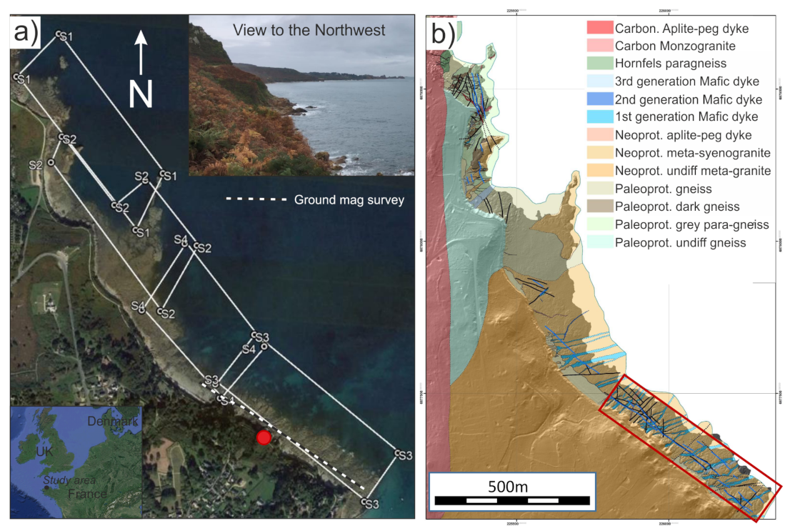
A 2 km long coastal section in northern Brittany, France, was selected as suitable test area for the CMAGTRES-S100 survey system (Figure 8a). Apart from its geological setting [23,24,25,26,27,28], the area was chosen for its operational complexity, providing an optimal setting for evaluating not only the output data quality but also the operational efficiency and flexibility of the survey system.
The study area consists of an inter-tidal zone, located off a prominent coastal cliff that rises abruptly in places more than 20 m from the beach. In the southeastern part of the study area, private properties extend to the edge of the cliff, preventing direct access and blocking the sight, while in the northwestern part, the area just landwards of the cliff is a popular area for outdoor activities. At low tide, the accessible, 40–150 m wide, part of the beach, is composed of rocky outcrops (topographic highs) that are separated by intervening lows. The lows are completely covered by small-to-large boulders. At high tide (up to 10 m amplitude), the sea advances to the foot of the cliff. As a result, the boulder field is wet and slippery, which makes the beach non-ideal for ground geophysical surveying in general, but also for UAV take-off and landing. Hence, patches of small flat areas along a path on top of the cliff were used for take-off and landing.
The physical setting of the survey area, combined with numerous safety issues relating to third parties entering the flight area or the take-off and landing safety zone, made the operation complex. A high degree of efficiency and yet careful planning was needed to take advantage of the few quiet moments in between the disturbances.

3.2. Geological Setting

The study area is located in a remnant of the Neoproterozoic Panafrican orogeny, known as the Cadomian belt, in the northern part of the Armorican massif [25] (Figure 8b). Along the coast, Neoarchean gneisses crop only on a small surface between the Variscan Ploumanac’h granite and the Cadomian Perros granite [27]. Light-colored layered gneisses composed of K-feldspar, plagioclase, quartz and biotite represent probable volcano-sedimentary metasediments, intruded by some porphyric orthogneiss intrusions. The trend of the metamorphic foliation is, on average, N160 E with a dip of 65 to the SW. The Perros monzogranite is fine to middle-grained granite composed of 3–5 mm ovoid quartz, K-feldspar, plagioclase and biotite with sometimes some muscovite. Both the Neoarchean gneiss and the Cadomian Perros granite are crosscut by three generations of mafic dykes [23,26,28]. The first generation corresponds to diabase dykes that trend N60 to N45 E with a near vertical dipping. The dykes are themselves crosscut by low-angle reverse faults that contain strongly altered phlogopite-bearing mafic dykes that represent the second generation. These faults and second generation of dykes trend N130 E in the east, within the Perros granite, to N170 E in the Neoarchean gneiss. The dip is, on average, 35 to the west. Finally, the third generation corresponds to subvertical N60 E diabase dykes that crosscut previous mafic dykes and faults. All these generations of mafic dykes and their host rocks are finally crosscutted by the emplacement of the Variscan Ploumanac’h complex (made of monzogranite, syenogranite, gabbro and granite intrusion), a N70 to N130 E trending swarm of pegmatite aplite subvertical dykes. Some of these pegmatites contain disseminated magnetite. Locally, along the contacts between the first and the second generation of mafic dykes and the Perros granite, numerous decametric to pluri-metric zones of diabase and granite are transformed into skarnoid assemblage, composed of garnet, magnetite, epidote, albite, quartz, pyrite, molybdenite and scheelite. The magnetite amount reaches 50% volume or even more in some areas [24].

4. Data Collection

The UAV magnetic test survey of the CMAGTRES-S100 survey system was carried in the end of October 2019 with the purpose of evaluating the performance of the prototype survey system in non-optimal weather conditions, i.e., few available daylight hours, medium to low temperatures (8–10 C) and medium winds (∼8 m/s). Due to local flight restrictions, the 2 km long coastal section (Figure 8a) was divided into four partly overlapping sub-surveys (named S1 to S4) with sizes of ∼500 × 250–300 m. The four sub-surveys extend across the outer beach and the inner sea. All surveys were flown with a 200 Hz sampling rate. Survey line spacing was set to 10 m and the lines were designed sub-parallel to the coast, i.e., perpendicular to the expected (magnetically) dominant geological strike of the coastal dykes and fault systems (Figure 8b). For safety reasons (limited visual-line-of-sight), the surveys were not flown draped but at constant altitudes of ∼14–27 m (bird altitude) above mean sea level. An off-the-shelf DJI M210 quadcopter UAV was used for the campaign, and a GSM19W magnetometer basestation from Gemsystems was placed near the take-off location of sub-survey S1 and used for sampling the Geomagnetic diurnal variation.

4.1. Ground Magnetic Surveys

Ground magnetic surveys were collected on the beach during low-tide. The original intentions of these surveys were to compare against the UAV magnetic data as a tool of data quality assessment. However, given the extremely difficult walking conditions on the beach, the quality of the ground surveys was overall poor and the areas covered too small for comparison purposes. Only one of the ground surveys, collected in the area of sub-survey S3 (see location in Figure 8a), is, therefore, used for quality assessment of the UAV magnetic data. The ground magnetic dataset was collected with a GSM19W magnetometer, sampling at 5 Hz. Similar to the UAV magnetic surveys, a GSM19W magnetometer base station was used to monitor the diurnal variation.

4.2. Photogrammetry Survey

UAV photogrammetry data were also collected during the test campaign as a means to assess the quality of the UAV magnetic data by correlating magnetic anomalies to visual surface geology on the beach as interpreted from the photogrammetry output data. The photogrammetry data were collected only in the southeastern (sub-survey S3) part of the study area, where prominent dykes and fault systems are present. The outline of the survey is shown by a red rectangle in Figure 8b. We collected the photogrammetry data using a Micasense RedEdge-MX mounted on the DJI M210 and equipped with a Micasense DLS 2 positioning sensor (Bands collected: Blue, Green, Red, NIR, Red edge).
The data were collected at an altitude of 72 m to 75 m, with a line spacing of 17 m (approx.) and a minimum overlap of 65%. In total, three survey lines were collected in an area of 0.061 km 2 and a total of 785 (calibrated) images were taken.

5. Data Processing

5.1. UAV magnetic data

Standard processing steps were applied to each sub-survey UAV magnetic data set (Figure 9): (i) Time-stamping and positioning, including parallax correction, (ii) Despiking of erroneous GNSS and magnetic values, (iii) Diurnal correction, (iv) Correction of the main and super-regional magnetic field using the CHAOS X7 model of [29], (v) Moving mean filter and downsampling from 200 to 40 Hz, (vi) Survey line trimming, (vii) Survey line leveling using six iterations of the approach of [30] (see example in Figure S6, Supplementary Data), (viii) Micro-leveling [31], and (ix) reduction-to-pole. All processing and plotting was carried out using Matlab R2019b and Python.
Following the processing of the individual sub-surveys S1–S4, the sub-surveys were merged into one smooth magnetic surface representing the entire magnetic survey. This was done using a grid-merging method described by [32]. All sub-surveys were upward continued to a common altitude level (30 m) and regridded with a grid-spacing of 2.5 m. Next, the overlapping discrepancy RMS-values between the sub-surveys was determined and cumulatively minimized by applying a base level shift (0 order trend) to each of sub-grids S1, S2 and S3. Secondly, the RMS-values were sequentially minimized by applying a trend shift (1 order polynomial) using a finite difference method. Sub-grid S4 was set as the reference grid. S4 was measured at the highest altitude and, therefore, the effect of the upward continuation was smallest. The final part of the merging method included a feathering algorithm with the aim to remove any remaining overlap error and merge the four sub-grids into one grid. Here, we used a feathering approach also used in the GeosoftOasisMontaj software, where each grid point in the overlapping regions are assigned a value based on a weighted average of the merging grids.

5.2. Ground Magnetic Data

The ground magnetic data were processed in a simple manner by spike editing, removal of diurnal variation as monitored by a basestation, removal of the main and super-regional field, and reduction to the pole. The data were subsequently upward continued in the spectral domain to sub-survey S3 altitude for comparison purposes.

5.3. Photogrammetry

The photogrammetry data were processed without the use of Ground Control Points (GCPs) for two main reasons: (1) difficult to access the area; (2) surface geological structures of interest are bigger than the uncertainty of the on board gnss. We processed the data, utilizing the structure-from-motion approach, which involves the capture of multiple overlapping images of the ground from the same camera at different positions [33]. We used the Pix4D software and the following steps: (1) Compute true locations and the parameters of the original pictures using Pix4d Automatic Aerial Triangulation and Bundle Block Adjustment; (2) Point Cloud densification; (3) Generation of a DSM and orthophoto for each band; (4) Combining the Red, Green and Blue single band orthophotos into a single RGB orthophoto. Output resolution of the data (Average Ground Sampling Distance) was 4.87 cm/pixel.

6. Results

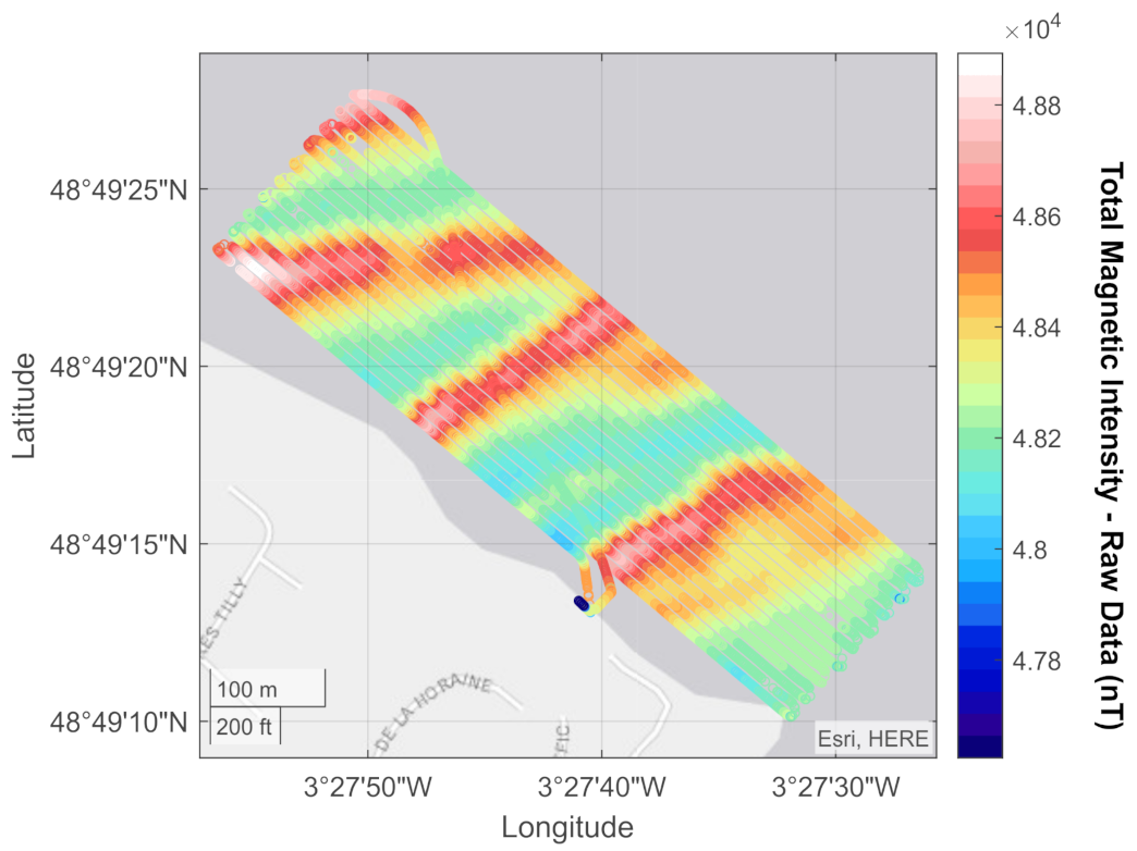
An example of raw magnetic survey data (following despiking) is shown in Figure 10 for sub-survey S3. This sub-survey is located in the southeastern study area and covers the prominent coastal dykes and magnetite-rich fault contacts that outcrop along the beach (Figure 8).
The raw S3 line data (Figure 10) display three NE- to ENE-trending magnetic highs that cross-cut the S3 sub-survey. A histogram plot of the fourth order difference noise estimation for sub-survey S3 is shown in Figure 11. In general, the noise level of the CMAGTRES-S100 survey system is about ±0.02 nT, which is well below the typical industry-level of data quality of ±0.1 nT [34].
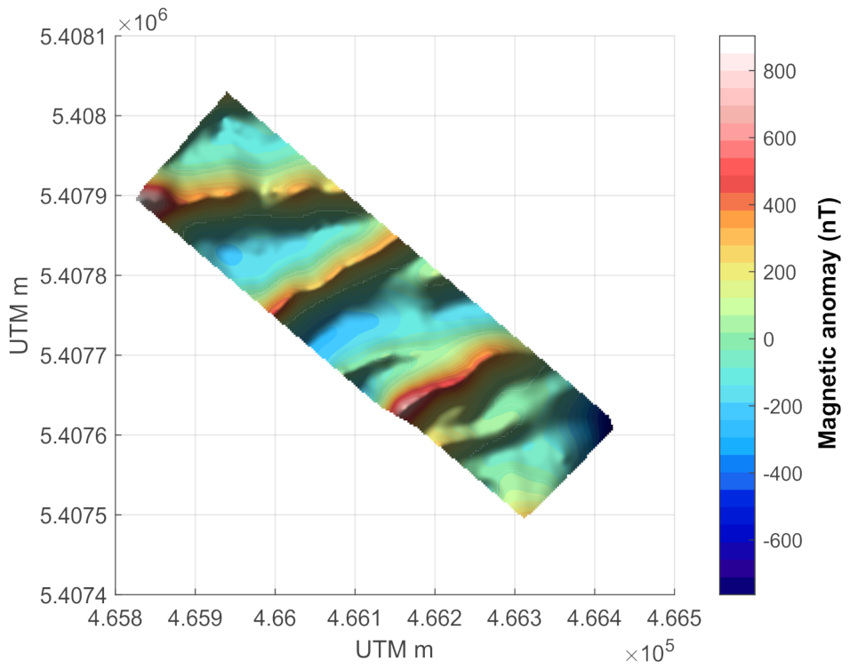
An example of the final anomaly data of sub-survey S3 is shown in Figure 12, following a full processing and gridding of the data. It is evident that the processing has succeeded in removing the slight horizontal offset observed in the raw data between neighboring lines and to create a smooth magnetic anomaly dataset. Subtle elongated, NE- to ENE-trending anomalies are now visible in the data in between the three prominent magnetic highs observed in the raw data (Figure 10). The NE- to ENE-trending anomaly signal reflects the dominant trend of the mafic dykes and magnetite-rich fault contacts in the area.

6.1. Merged Anomaly Grid

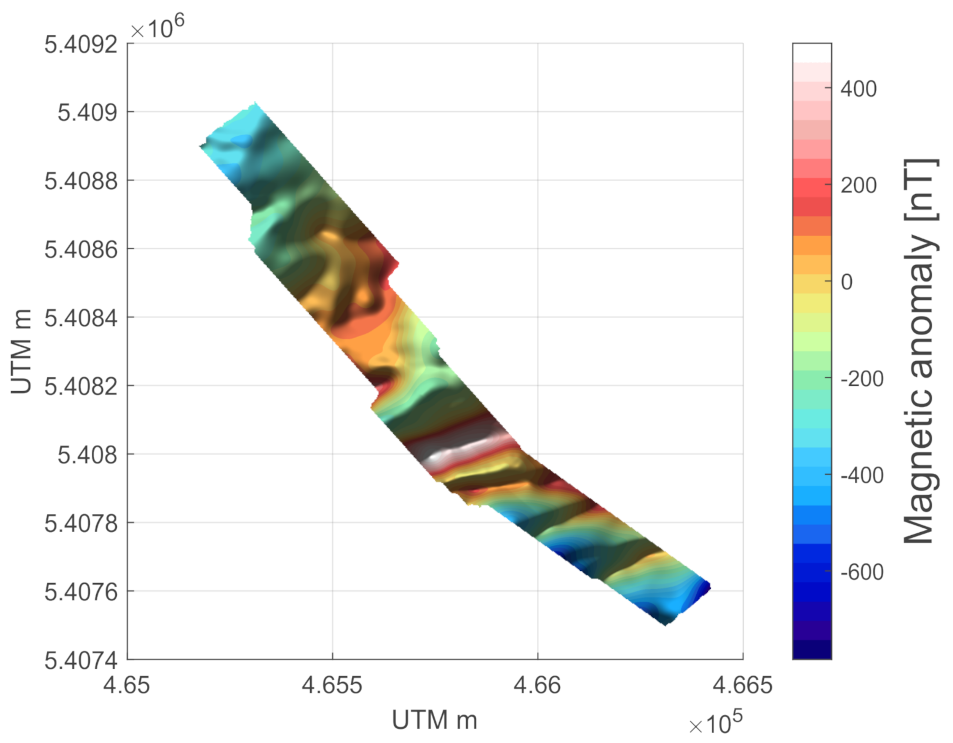
The complete magnetic anomaly grid for the coastal section (Figure 13) indicate that the mapped area may be divided into a southern and northern section. The northern section is defined by intermediate-to-long wavelength low-to-medium amplitude anomalies without clear evidence of a dominant strike. Thus, the northern anomalies are probably related to magnetic contrasts between the three main basement units, the two granites and the gneiss, which have rather low magnetic susceptibilities and contrasts (Figure 8b). In contrast, the southern section is defined by prominent elongated positive magnetic anomalies that cross-cut the survey area in a NE- to ENE-direction. The southern anomalies mostly reflect the high magnetic contrasts between Perros granite and the skarnified dykes.

6.2. Photogrammetry

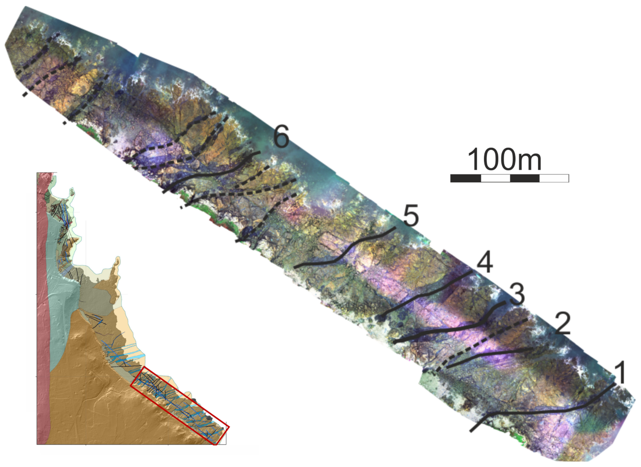
An orthophoto of the processed photogrammetry data from the sub-survey S3 area are depicted in Figure 14. The plot is overlain by an interpretation of visually identifiable dykes and fault zones. The identified structures will be used as input for a discussion of the UAV magnetic data quality (see below).

7. Discussion

7.1. Operational Efficiency and Flexibility of the CMAGTRES-S100

The CMAGTRES-S100 survey system was designed with three key design purposes in mind, operational efficiency, operational flexibility and high data quality.
The operational efficiency is critical when deadlines are tight or when operating in non-optimal weather conditions where the available hours for safe flying during a day are few. Efficiency is also critical in areas where the drone air space is open for a limited period only. This includes areas near or within airports or areas open to the public in general, where it may be possible to survey only during very early or late hours of the day (if night time flying permission is not permitted or possible). The operational flexibility is critical when surveying is needed in areas that are not accessible by car and/or where take-off and landing zones are confined to only a small spot on the ground.
The operational efficiency of the CMAGTRES-S100 is increased by its quick and easy deployment, extreme light-weight for extended operational range, and its aerodynamic stability at high surveying speeds; all parameters that increase the operational efficiency and allow the user to map large areas within a limited amount of time.
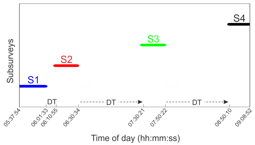
During the test flights in France, the CMAGTRES-S100 survey system behaved well in terms of aerodynamic stability of the bird and the ability of the M210 UAV to stay on the pre-defined survey tracks, while keeping the high survey speed. The survey system successfully collected magnetic and positional data in all four (S1–S4) polygon areas (Figure 8a). Sub-survey S1 was started at 05:38 a.m. on 30 October 2019, due to the prediction of strong winds (+12 m/s) in the afternoon. Sub-survey S4 was completed at 09:09 a.m. the same day, i.e., an area of ∼2.0 × 0.3 km was mapped with a 10 m line spacing in ∼3.5 h by four partly overlapping surveys. A plot of the time and downtime (DT) for the four sub-surveys is shown in Figure 15. The total downtime was about 130 min, which adds up to ∼60% of the total surveying time. The downtime was related to (i) re-mobilisation between the four sub-surveys, i.e., changing take-off locations on foot or by car, (ii) safety issues, i.e., pauses caused by incidents with the public in the survey area (people gathering to look or passing nearby the take-off and landing area or people walking or sailing within one of the four survey areas), or (iii) technical issues, i.e., a data logging issue was encountered between sub-survey S3 and S4, which delayed the completion of the campaign by 10 min. Overall the operational efficiency demonstrated in Figure 15 indicates that the CMAGTRES-S100 survey system is well suited for carrying out sub-regional scale magnetic surveys in areas where efficiency is needed.
The flexibility of the CMAGTRES-S100 system mainly deals with the combined light-weight of the survey system as a whole (5.9 kg), that is, including the M210 UAV. The low weight makes it easy to carry in the field. However, flexibility also concerns the small take-off and landing area needed. The latter was tested during sub-survey S3, which was completed from a small (∼3 × 3 m) take-off and landing spot on the very edge of the coastal cliff. The flexibility of the whole system is critical when one needs to survey in remote areas that are far away and that may not be accessible by road. Such a test was not conducted in France. However, another test was also conducted in remote conditions in northern Iceland in 2019, where the combined UAV and CMAGTRES-S100 survey system was carried several kilometers in rough terrain before being deployed. Data from this campaign are currently being processed for publication.

7.2. Quality of Data—Comparison with Ground Magnetic Data and Geology

The quality of airborne magnetic data can be assessed in a number of ways. We have already shown that the noise level of the survey data is low (±0.02 nT) as estimated by the fourth order difference noise shown in Figure 11. The quality of the data can further be assessed by displaying the final anomaly grid with sun-shading to highlight any residual flight-line features. Additionally, by calculating gradients of the total field anomaly, one may enhance not only short wave-length anomalies in the data but also noise which has not be properly removed. Finally, the resolution and precision of the UAV magnetic data may be assessed by correlating the magnetic anomaly data with independent data sets, such as ground magnetic data or surface geology, which may be mapped in the field or by visual inspection of an orthophoto produced by UAV photogrammetry.
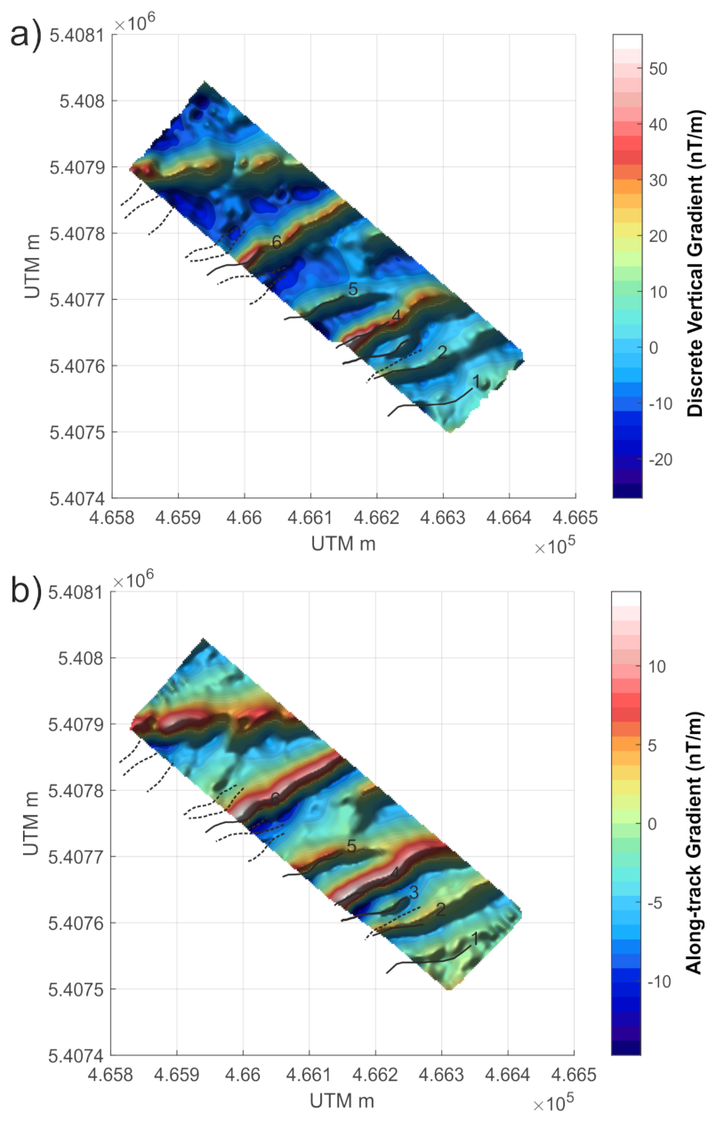
In Figure 16, we have calculated the discrete vertical gradient and the along-track gradient of the final sub-survey S3 anomaly data (see original data in Figure 12). Additionally, shown in Figure 16 are the NE- to ENE-trending mafic dykes and magnetite-rich fault contacts, as mapped from the orthophoto in Figure 14. Overall, the smoothness of the gradient plots in Figure 16 support the conclusion of high quality data. Both the vertical and the along-track transformation display short wavelength magnetic anomalies that are related to the (magnetic) surface geology seen in the photogrammetry data. Some of the most prominent anomalies (e.g., anomaly 6 in Figure 16) reflect the magnetite-rich fault contacts in the area. However, it is also evident that the UAV magnetic data are not able to resolve the smallest geological structures (shown as dashed lines in Figure 16). This is most likely related to the fact that sub-survey S3 was flown with a bird altitude of 14 m above mean sea level.
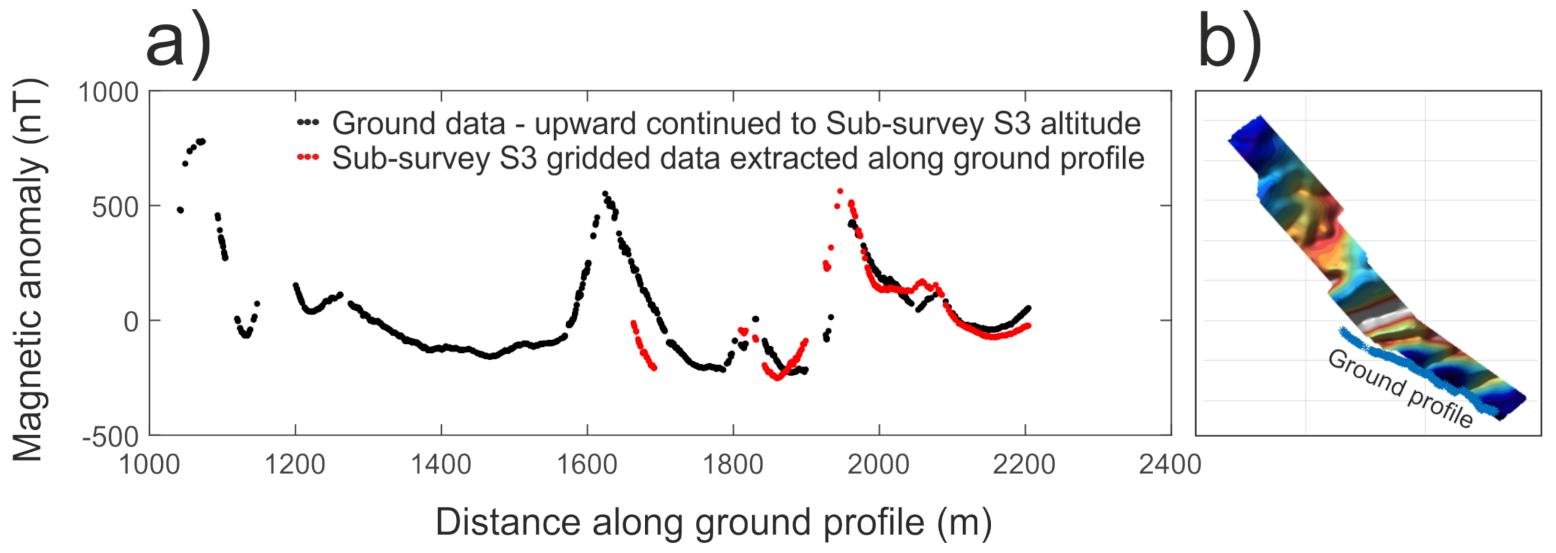
In Figure 17, we compare the ground magnetic data with data from sub-survey S3. For safety reasons, the ground survey was conducted on the inner beach in order for the surveyor to return before the high tide (see location of the ground magnetic profile in Figure 8a). The ground magnetic data, therefore, overlap only with part of sub-survey S3. Within the overlap areas, however, the two data sets display an overall similar behavior in terms of anomaly amplitude and anomaly peak. When combined with the strong correlation between UAV magnetic anomalies and surface geology (Figure 16), the correlation between the UAV magnetic data and the ground magnetic data support the conclusion that the CMAGTRES S-100 survey system provides real and high-quality magnetic data.

7.3. Benchmarking against Commercially Available Magnetometer Bird Systems

As compared to commercially available systems, such as the MagArrow, the AirBird and the DroneMag (Figure 3), the CMAGTRES-S100 survey system provides the lowest total weight of only 5.9 kg (including the UAV and all batteries) of which the full magnetic payload (all included) weighs ∼1.2 kg. The low combined weight (and low dimensions) of the bird and towing UAV makes the survey system ideal for surveys located in areas that cannot be accessed by car. In addition, the system is easy reparable in the field since all containing parts (except the strong connecting carbon fibre tube) are 3D printed, i.e., the surveyor may simply print additional spare parts of the bird to bring in the field. This is not an option for the MagArrow or the AirBird which are produced of carbon fiber and fibre glass.
In terms of aerodynamic stability at high speeds and, thereby, operational efficiency, the CMAGTRES-S100 bird has shown to be stable at 14 m/s and even the medium-sized DJI M210 showed no problems keeping up this speed throughout the test survey, i.e., the CMAGTRES-S100 provides superior operational efficiency as compared to the MagArrow, DroneMag and Airbird. The focus on high speeds, on the other hand, makes the CMAGTRES-S100 less optimal for areas with steep topography or surveys close to the ground (e.g., UXO mapping).
In terms of data quality, the magnetometer evaluation provided in Section 2.2 and the estimated low noise level of ±0.02 nT in Figure 11 indicate that the CMAGTRES-S100 provides superior data quality in terms of magnetic accuracy, noise and sensitivity as compared to, e.g., the MagArrow of Geometrics. MagArrow carries an MFAM magnetometer, which was shown to be inferior to the QTFM of the CMAGTRES-S100. Importantly, the MFAM sensors of the MagArrow are located in the vicinity (<1 m) of onboard bird electronics (sensor control box, GPS antenna, data logging module, and battery) and the sensors are surrounded by a conducting carbon fiber shell. As compared to the somewhat heavier AirBird of Gemsystems, it is expected that the CMAGTRES-S100 provides lower data quality, since the AirBird carries a GSMP-35u sensor in its tail. The AirBird sensor is well shielded (>1 m) from all onboard bird electronics and is located inside a non-conducting fiber glass tail.

7.4. Further Improvements

In order to minimize the overall weight of the CMAGTRES-S100 survey system, some compromises were made to the initial design. Most importantly, an independent GNSS positioning system was not integrated in the bird itself. Instead, the data logging module affixed directly to the UAV frame was designed to connect and extract power as well as GNSS time and positioning information directly from the UAV, i.e., the positioning of the bird is based on a simple geometric calculation using the length of the towing cable and an assumption of the angle of the towing cable relative to a vertical line during flight. The optimal angle may be estimated by testing different “delays” in the data until a minimum “herring-bone” type pattern is observed. As shown in the final processed data (Figure 12 and Figure 16), the uncertainty on the bird positioning in the test survey appears to be small.
However, while significantly reducing the overall weight, magnetic noise and complexity of the magnetometer bird, the chosen solution introduces an increased uncertainty in the positioning of each data point as compared to an onboard GNSS solution. On the other hand, the typical light-weight positioning devices of UAV magnetometer bird systems, such as the MagArrow, provide a position (in optimal conditions) with an uncertainty of at least 1 m. One may, therefore, argue that by estimating the position of the bird by using the typical survey-grade UAV positioning system, as in the CMAGTRES-S100, one may obtain a comparable absolute uncertainty of each data point as in, e.g., the MagArrow. It is, however, not recommendable to employ the current CMAGTRES-S100 setup in areas—and for purposes—where a horizontal positioning of less than 10–20 cm is needed or in areas where the gradient is high. The latter may lead to errors that are too high to properly be processed and create a smooth result.
Following on the results and experiences obtained in this study, a number of improvements are obvious for future versions, upgrades and tests of the CMAGTRES-S100 survey system. However, it remains critical to not integrate any positioning devices (GNSS-IMU or altimeter) inside the bird itself in order to maintain a noise-free environment in the bird and a minimum total weight of the survey system, thereby maintaining a high degree of operational flexibility and efficiency. Currently, the data logging module, affixed to the UAV, extracts and logs GNSS time and positioning from the UAV. One way to increase the positional accuracy of the magnetometer bird—without compromising the noise levels—may be to also log the 3D attitude information of the UAV during flight, as recorded by its onboard IMU(s). The attitude of the UAV is a function of the angle of the UAV while surveying, which again reflects whether the UAV is flying upwind or downwind relative to the UAV speed. By testing several scenarios of speed and wind conditions while overflying, e.g., a small magnetic point source precisely positioned on the ground, one may be able to better estimate the true angle of the bird towing cable simply from the extracted GNSS-IMU information of the UAV and, hence, to obtain a more precise xyz-positioning estimate of each data point in the bird.

8. Conclusions

This study presents the various considerations and choice made during the development of a highly efficient light-weight single-sensor total field UAV-integrated magnetometer bird system—the CMAGTRES-S100. We discuss elements such as choice of sensor, design criteria of the bird, validation and testing of the system and the quality of the final output data against geological information and ground magnetic data.
A high-speed magnetometer bird is presented. The bird is designed for speeds of 14 m/s (50 km/h) and can be towed by a medium sized UAV such as the DJI M200 series. The total weight of the bird and UAV is around 6.5 kg, which allows the user of the system to diverge from roads and deploy the system in remote areas.
The high speed of the system makes it operationally efficient. We present a case study from France, where a 2.0 × 0.3 km area was mapped with a 10 m line-spacing by four sub-surveys in 3.5 h, of which more than 2 h were used on remobilisation and safety clearance of the area.
A noise level of ±0.02 nT is estimated based on the study in France. Together with our analysis of the data, showing a good correlation with the geology, we present a new magnetometer bird system that has proven to provide high-quality total field data at km scale ranges.

Supplementary Materials

The following are available online at https://www.mdpi.com/2072-4292/13/4/649/s1.

Author Contributions

Conceptualization, A.D., G.M. and T.M.R.; Methodology, A.D. and E.L.S.d.S.; software for data acquisition and processing, A.D., E.L.S.d.S. and J.T.P.; fieldwork, A.D., G.M., T.M.R., E.G., E.L.S.d.S. and J.L.; writing—original draft preparation, A.D.; writing—review and editing, A.D., G.M., T.M.R., E.G. and E.L.S.d.S.; funding acquisition, A.D., G.M. and T.M.R. All authors have read and agreed to the published version of the manuscript.

Funding

This research was funded by EIT-RM (https://eitrawmaterials.eu/project/muverdrone/).

Acknowledgments

We greatly appreciate the initial sensor evaluation work and early magnetometer bird prototyping carried out by N. Skjødt and D. Bambery as part of their Msc theses at DTU Space in 2018. Thanks to Lars W. Pedersen (DTU Space) for assisting with ideas for sensor testing and allowing access to the Brorfelde Geomagnetic Observatory. We would like to thank the remaining members of the CMAGTRES group, in particular Vamsi Krishna, for assisting with ideas on the bird development. Magnetometer data from the Brorfelde (BFE) observatory were provided by the National Space Institute at the Technical University of Denmark (DTU Space).

Conflicts of Interest

The authors declare no conflict of interest.

References

  1. Cordell, L.; Grauch, V. Mapping basement magnetization zones from aeromagnetic data in the San Juan Basin, New Mexico. In The Utility of Regional Gravity and Magnetic Anomaly Maps; Society of Exploration Geophysicists: Tulsa, OK, USA, 1985; pp. 181–197. [Google Scholar]
  2. Hood, P.J.; Teskey Dennis, J.T. Aeromagnetic gradiometer program of the Geological Survey of Canada. Geophysics 1989, 8, 1012–1022. [Google Scholar]
  3. Isles, D.J.; Rankin, L.R. Geological Interpretation of Aeromagnetic Data; Society of Exploration Geophysicists and Australian Society of Exploration: Tulsa, OK, USA, 2013. [Google Scholar]
  4. Døssing, A.; Jackson, H.R.; Matzka, J.; Einarsson, I.; Rasmussen, T.M.; Olesen, A.V.; Brozena, J. On the origin of the Amerasia Basin and the High Arctic Large Igneous Province—Results of new aeromagnetic data. Earth Planet. Sci. Lett. 2013, 363, 219–230. [Google Scholar] [CrossRef]
  5. Fassbinder, J.W. Seeing beneath the farmland, steppe and desert soil: Magnetic prospecting and soil magnetism. J. Archaeol. Sci. 2015, 56, 85–95. [Google Scholar] [CrossRef]
  6. Billings, S.D. Discrimination and classification of buried unexploded ordnance using magnetometry. IEEE Trans. Geosci. Remote Sens. 2004, 42, 1241–1251. [Google Scholar] [CrossRef]
  7. Philip, H.E. Magnetic Surveying Apparatus. U.S. Patent 2,335,117, 23 November 1943. [Google Scholar]
  8. Lundberg, H. Results obtained by a helicopter borne magnetometer: Transactions. Can. Inst. Min. Metall. 1947, 50, 392–400. [Google Scholar]
  9. Dobrin, M.B.; Savit, C.H. Introduction to Geophysical Prospecting; McGraw-Hill: New York, NY, USA, 1960; Volume 4. [Google Scholar]
  10. Witherly, K. Hans Lundberg: Canada’s (and possibly the World’s) first minerals geophysicist is inducted into the Canadian Mining Hall of Fame. Preview 2020, 2020, 12–16. [Google Scholar] [CrossRef] [Green Version]
  11. Walter, C.; Braun, A.; Fotopoulos, G. High-resolution unmanned aerial vehicle aeromagnetic surveys for mineral exploration targets. Geophys. Prospect. 2020, 68, 334–349. [Google Scholar] [CrossRef]
  12. Wood, A.; Cook, I.; Doyle, B.; Cunningham, M.; Samson, C. Experimental aeromagnetic survey using an unmanned air system. Lead. Edge 2016, 35, 270–273. [Google Scholar] [CrossRef]
  13. Gavazzi, B.; Le Maire, P.; Munschy, M.; Dechamp, A. Fluxgate vector magnetometers: A multisensor device for ground, UAV, and airborne magnetic surveys. Lead. Edge 2016, 35, 795–797. [Google Scholar] [CrossRef] [Green Version]
  14. Malehmir, A.; Dynesius, L.; Paulusson, K.; Paulusson, A.; Johansson, H.; Bastani, M.; Wedmark, M.; Marsden, P. The potential of rotary-wing UAV-based magnetic surveys for mineral exploration: A case study from central Sweden. Lead. Edge 2017, 36, 552–557. [Google Scholar] [CrossRef]
  15. Vadim, T.; Alexander, P.; Vasily, A.; Dmitry, K. Unmanned airborne magnetic survey technologies: Present and future. In Recent Advances in Rock Magnetism, Environmental Magnetism and Paleomagnetism; Springer: Berlin/Heidelberg, Germany, 2019; pp. 523–534. [Google Scholar]
  16. Walter, C.; Braun, A.; Fotopoulos, G. Spectral analysis of magnetometer swing in high-resolution UAV-borne aeromagnetic surveys. In Proceedings of the 2019 IEEE Systems and Technologies for Remote Sensing Applications Through Unmanned Aerial Systems (STRATUS), Rochester, NY, USA, 25–27 February 2019; pp. 1–4. [Google Scholar]
  17. Kolster, M.E.; Døssing, A. Scalar magnetic difference inversion applied to UAV-based UXO detection. Geophys. J. Int. 2020, 224, 468–486. [Google Scholar] [CrossRef]
  18. Le Maire, P.; Bertrand, L.; Munschy, M.; Diraison, M.; Géraud, Y. Aerial magnetic mapping with an unmanned aerial vehicle and a fluxgate magnetometer: A new method for rapid mapping and upscaling from the field to regional scale. Geophys. Prospect. 2020, 68, 2307–2319. [Google Scholar] [CrossRef]
  19. Dentith, M.; Mudge, S.T. Geophysics for the Mineral Exploration Geoscientist; Cambridge University Press: Cambridge, UK, 2014. [Google Scholar]
  20. Edelstein, A. Advances in magnetometry. J. Phys. Condens. Matter 2007, 19, 165217. [Google Scholar] [CrossRef] [Green Version]
  21. Hovde, D.; Prouty, M.; Hrvoic, I.; Slocum, R. Commercial magnetometers and their application. Opt. Magnetometry 2013, 2013, 387–405. [Google Scholar]
  22. Nayler, J. Dynamics of Atmospheric Flight, Bernard Etkin. Aeronaut. J. 1973, 77, 102. [Google Scholar]
  23. Auvray, B. Genèse et Evolution de la Croûte Continentale dans le Nord du Massif Armoricain. Ph.D. Thesis, Rennes University, Rennes, France, 1979. [Google Scholar]
  24. Chauris, L. A fissural pseudo-skarn with molybdenite and scheelite: Kerdu en Perros-Guirec (Massif Armoricain). Bull. De La Soci ’e T É Des Sci. Nat. De L’Ouest De La Fr. (1983) 1991, 13, 41–50. [Google Scholar]
  25. Egal, E.; Guerrot, C.; Le Goff, E.; Thiéblemont, D.; Chantraine, J. The Cadomian orogeny revisited in northern Brittany (France). Spec. Pap.-Geol. Soc. Am. 1996, 394, 281–318. [Google Scholar]
  26. Barboni, M.; Schoene, B.; Ovtcharova, M.; Bussy, F.; Schaltegger, U.; Gerdes, A. Timing of incremental pluton construction and magmatic activity in a back-arc setting revealed by ID-TIMS U/Pb and Hf isotopes on complex zircon grains. Chem. Geol. 2013, 342, 76–93. [Google Scholar] [CrossRef]
  27. Guennoc P., Feybesse J.-L. Explanatory note of the geological map of France 1: 50 000 scale. Perros Guirec sheet (170) 2015. [Google Scholar]
  28. Pochon, A.; Poujol, M.; Gloaguen, E.; Branquet, Y.; Cagnard, F.; Gumiaux, C.; Gapais, D. U-Pb LA-ICP-MS dating of apatite in mafic rocks: Evidence for a major magmatic event at the Devonian-Carboniferous boundary in the Armorican Massif (France). Am. Mineral. 2016, 101, 2430–2442. [Google Scholar] [CrossRef]
  29. Finlay, C.C.; Kloss, C.; Olsen, N.; Hammer, M.D.; Tøffner-Clausen, L.; Grayver, A.; Kuvshinov, A. The CHAOS-7 geomagnetic field model and observed changes in the South Atlantic Anomaly. Earth, Planets Space 2020, 72, 1–31. [Google Scholar] [CrossRef] [PubMed]
  30. White, J.C.; Beamish, D. Levelling aeromagnetic survey data without the need for tie-lines. Geophys. Prospect. 2015, 63, 451–460. [Google Scholar] [CrossRef] [Green Version]
  31. Minty, B. Simple micro-levelling for aeromagnetic data. Explor. Geophys. 1991, 22, 591–592. [Google Scholar] [CrossRef] [Green Version]
  32. Minty, B.R.; Milligan, P.R.; Luyendyk, T.; Mackey, T. Merging airborne magnetic surveys into continental-scale compilations. Geophysics 2003, 68, 988–995. [Google Scholar] [CrossRef]
  33. Westoby, M.J.; Brasington, J.; Glasser, N.F.; Hambrey, M.J.; Reynolds, J.M. ‘Structure-from-Motion’photogrammetry: A low-cost, effective tool for geoscience applications. Geomorphology 2012, 179, 300–314. [Google Scholar] [CrossRef] [Green Version]
  34. Coyle, M.; Dumont, R.; Keating, P.; Kiss, F.; Miles, W. Geological Survey of Canada Aeromagnetic Surveys: Design, Quality Assurance, and Data Dissemination; Geological Survey of Canada: Ottawa, OT, Canada, 2014; 48p. [Google Scholar]
Figure 1. Magnetic surveying by ground, helicopter (using a towed magnetometer bird) or airplane (using a tail stinger). The main pros and cons of each survey type are listed to the right. Modified from [11].
Remotesensing 13 00649 g001
Figure 2. Representative ways of mounting magnetometer systems on multi-rotor UAVs. (a) Fixed-boom setup; (b) Towed sensor setup; (c) Towed bird setup (solution provided in this study).
Remotesensing 13 00649 g002
Figure 3. Popular commercially available UAV (scalar field) magnetic survey systems. (a) MagArrow magnetometer bird (credit: Geometrics). (b) DroneMag towed magnetometer (credit: Gemsystems). (c) Airbird magnetometer bird (credit: Gemsystems).
Remotesensing 13 00649 g003
Figure 4. UAV magnetometers evaluated in this study (shown at roughly same scale). (a) MFAM magnetometer (only the two sensor heads are shown). (b) QTFM magnetometer of QuSpin Ltd. (c) GSMP-35u magnetometer of Gemsystems (credit: Gemsystems).
Remotesensing 13 00649 g004
Figure 5. Test 1. (a) Calculated gradients between test sensors and the Brorfelde Geomagnetic Observatory (BGO) as a function of time. (b) Histogram plots of the calculated gradients.
Remotesensing 13 00649 g005
Figure 6. Test 4. (a) Gradient between the GSMP-35u and QTFM against the BGO observatory magnetometer as a function of time. (b) Histogram plots of the calculated gradients.
Remotesensing 13 00649 g006
Figure 7. (a) Towed bird assembly representation with parts description. The figure also shows the body fixed reference frame used to further describe the bird’s stability. With the × axis along the bird’s fuselage, the y axis pointing left and the z axis pointing down, with the roll, pitch and yaw angles defined as a rotation around those axis, respectively. c g location marked with a circle and cross. Main body fixed axis defined. (b) Towed bird position relative to the UAV (in left forward flight). (c) Side and rear view of the towed bird assembly, with main dimensions in mm.
Remotesensing 13 00649 g007
Figure 8. Study area. (a) Google Earth image of the coast. White polygons outline the four UAV magnetic sub-surveys S1–S4 collected. Dashed black-white line: Ground magnetic survey. Red dot: location of where inset photo was taken. (b) Geological setting of the coast. Red polygon: outline of UAV photogrammetry survey.
Remotesensing 13 00649 g008
Figure 9. Main processing steps for the four UAV-borne magnetic sub-surveys S1–S4.
Remotesensing 13 00649 g009
Figure 10. Raw data of sub-survey S3.
Remotesensing 13 00649 g010
Figure 11. Fourth order difference noise estimate of the trimmed survey data, downsampled to 40 Hz.
Remotesensing 13 00649 g011
Figure 12. Final Reduced-to-Pole magnetic anomaly grid of sub-survey S3. The data were gridded using a grid cell size of 2.5 m.
Remotesensing 13 00649 g012
Figure 13. Merged sub-surveys S1–S4.
Remotesensing 13 00649 g013
Figure 14. Orthophoto from UAV photogrammetry of the southeastern part of the study area, near sub-survey S3. Inset figure: Simplied geology map (see also Figure 8b) with the location of the photogrammetry survey outlined by a red rectangle. Mafic dykes and magnetite-rich (skarnified) fault contacts are mapped by the visual inspection of the map and observations in the field. Prominent dykes and magnetite-rich fault contacts are shown as full lines and have designated numbers 1–6. Less prominent features are shown by dotted lines. An uninterpreted version of the figure is shown in Figure S7, Supplementary Data.
Remotesensing 13 00649 g014
Figure 15. Plot of the surveying time (including survey lines, transit lines, take-off and landing) for the four sub-surveys: S1 (blue), S2 (red), S3 (green) and S4 (black). D T : Downtime between the individual sub-surveys (see text for details).
Remotesensing 13 00649 g015
Figure 16. Sub-survey S3 transformations. (a) Discrete vertical derivative with dykes and magnetite-rich fault zones identified from photogrammetry data. (b) Along-track gradient.
Remotesensing 13 00649 g016
Figure 17. (a) Comparison of ground magnetic data and sub-survey S3 data. Note that sub-survey S3 data were extracted in data points where the two data sets overlap. (b) Magnetic anomaly map of all four sub-surveys S1–S4 overlain by the location of the ground profile.
Remotesensing 13 00649 g017
Table 1. Operational criteria for the survey system.
Surveying speed∼14 m/s
Sensor typeTotal-field (scalar)
Sensor sampling rateMinimum 10–20 Hz
Maximum weight, incl. UAV and batteries6–7 kg
Table 2. Sensor specifications provided by manufacturers for the Low Heading Error MFAM (Geometrics), GSMP-35u (Gemsystems) and QTFM (Quspin).
NameGSMP-35uMFAMQTFM
TypePotassiumCaesiumRubidium
Sensitivity (pT)0.3@1Hz/3@20Hz7/ Hz 1/ Hz
Resolution (nT)0.00010.0001NA
Absolute Accuracy (nT)±0.1NANA
Dead Zones ( )±10 Po/±10 Eq±35 Po *±7 Eq
Heading Error (nT)±0.05±7.5<±1.5
Dynamic Range (nT)15,000–120,00020,000–100,0001000–100,000
Gradient Tolerance (nT/m)50,000NA10,000
Sampling Rate (Hz)1–20 Hz1000max 400
Power consumption (W)121–22
Total weight (g) (excl cables)1000230150
Sensor head dimensions (cm)16.1/6.43.3/2.5/3.2/1.9/1.9/4.7
Sensor control box dimensions (cm)23.6/5.6/3.912.0/5.2/2.21.9/3.5/8.9
* The dead zone of the MFAM may be eliminated by using a dual sensor configuration (currently done in the MagArrow bird of Geometrics). Abbreviations: Po, Polar Dead Zone; Eq, Equatorial Dead Zone.
Table 3. Design criteria for the magnetometer bird.
Magnetometer typeCompatible with a Quspin QTFM magnetometer.
Magnetometer integrationRigidly affix the sensor head and control box and ensure a minimum stand-off distance from the sensor head to any on-board electronics of at least 1 m.
Materials and WeightManufactured by low-weight materials to ensure a total payload weight below ∼1200 g (incl bird, cables, magnetometer, logging device, power supply and positioning).
Sensor head shellManufactured exclusively with non-magnetic/non-conductive materials.
Surveying speedStatically and dynamically stable in roll, pitch and yaw at minimum 14 m/s forward flight, without requiring any control input or automatic actuation.
UAVCompatible with the medium-sized DJI M210.
Publisher’s Note: MDPI stays neutral with regard to jurisdictional claims in published maps and institutional affiliations.