
Ground Penetrating Radar Survey of the Floor of the Accademia Gallery (Florence, Italy)

 ,
,  , ,
, ,  ,
, 

Abstract
:
1. Introduction
2. Materials and Methods
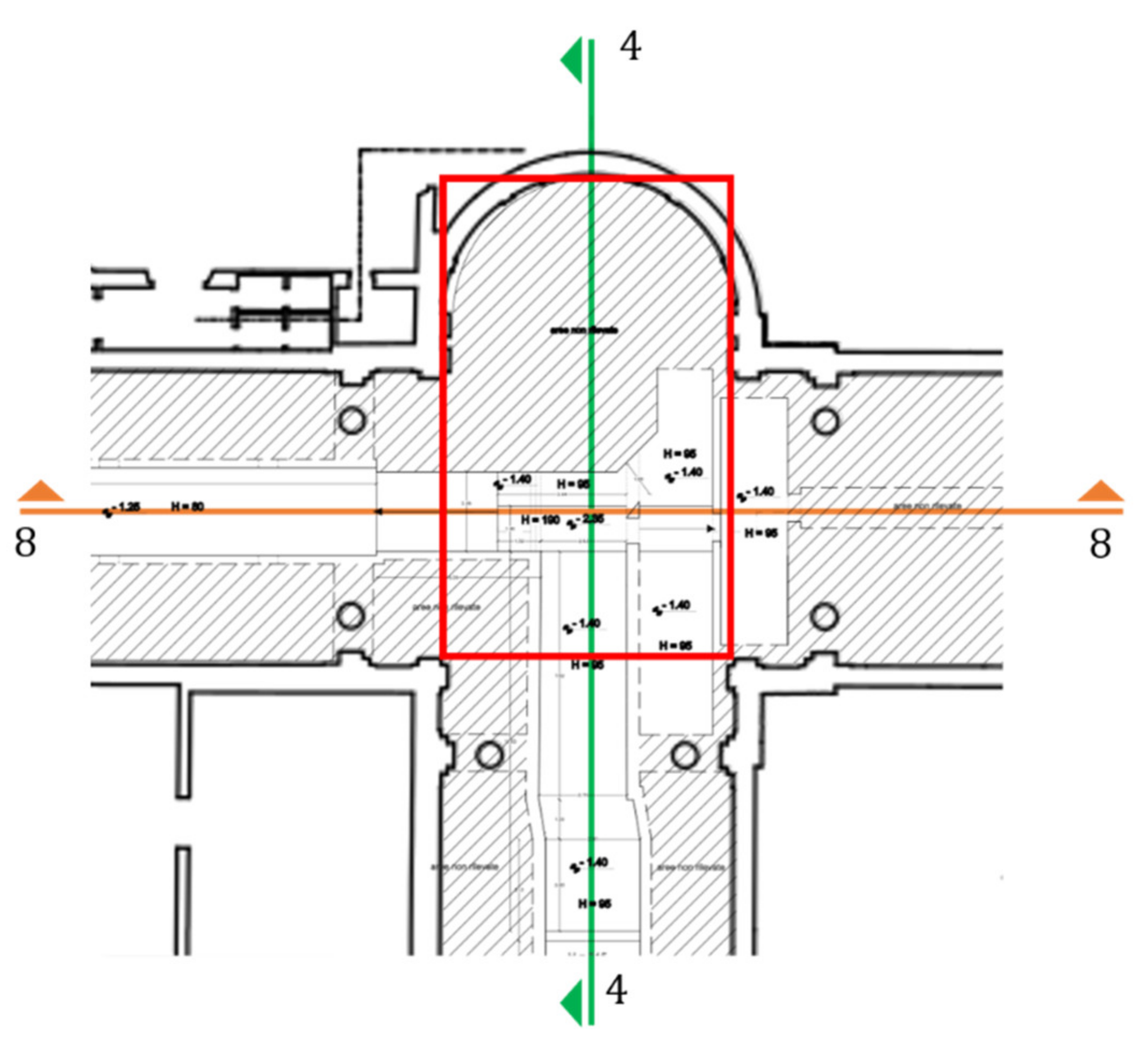
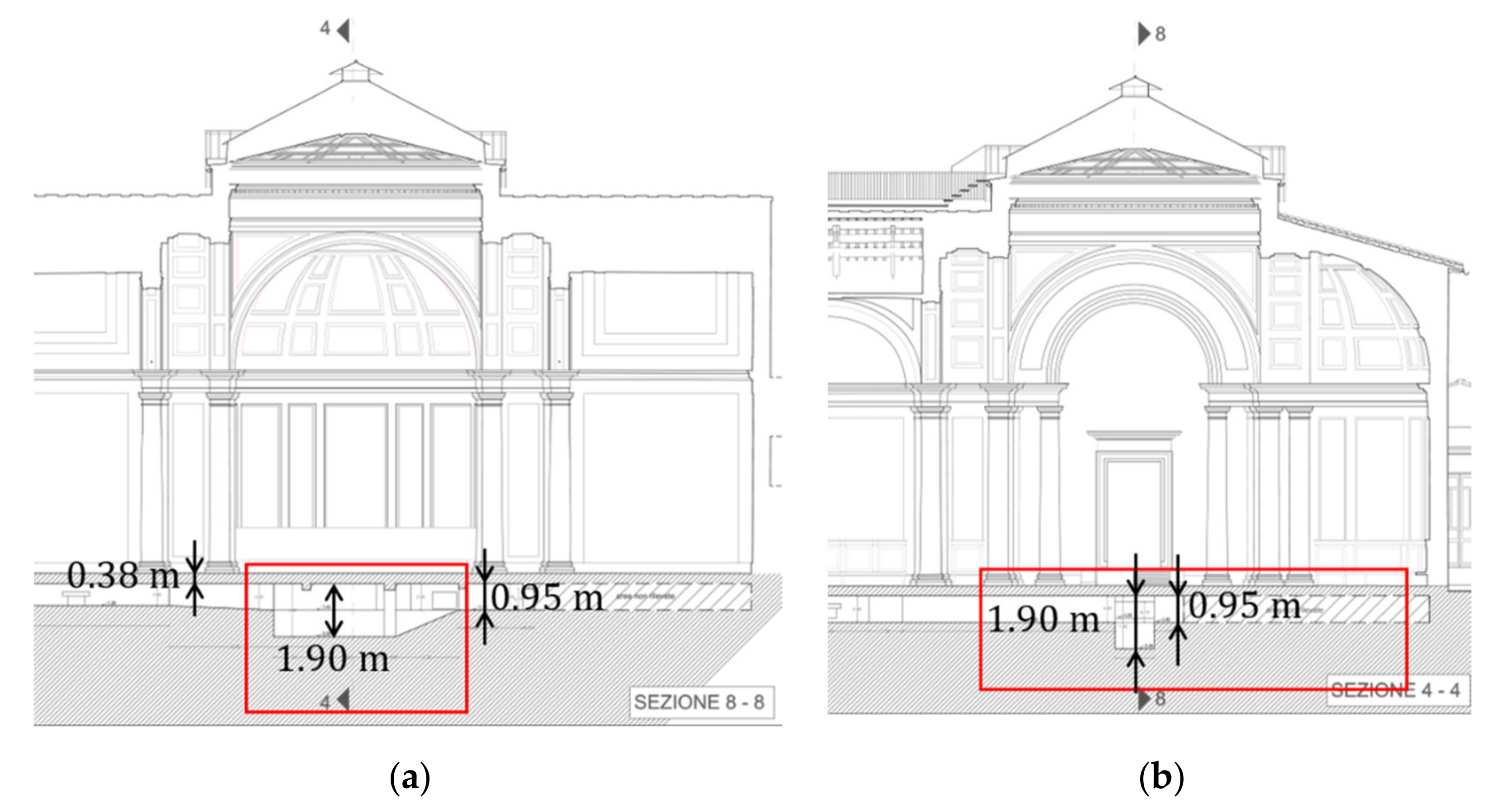
2.1. The “Tribuna”
2.2. Historical Documentation
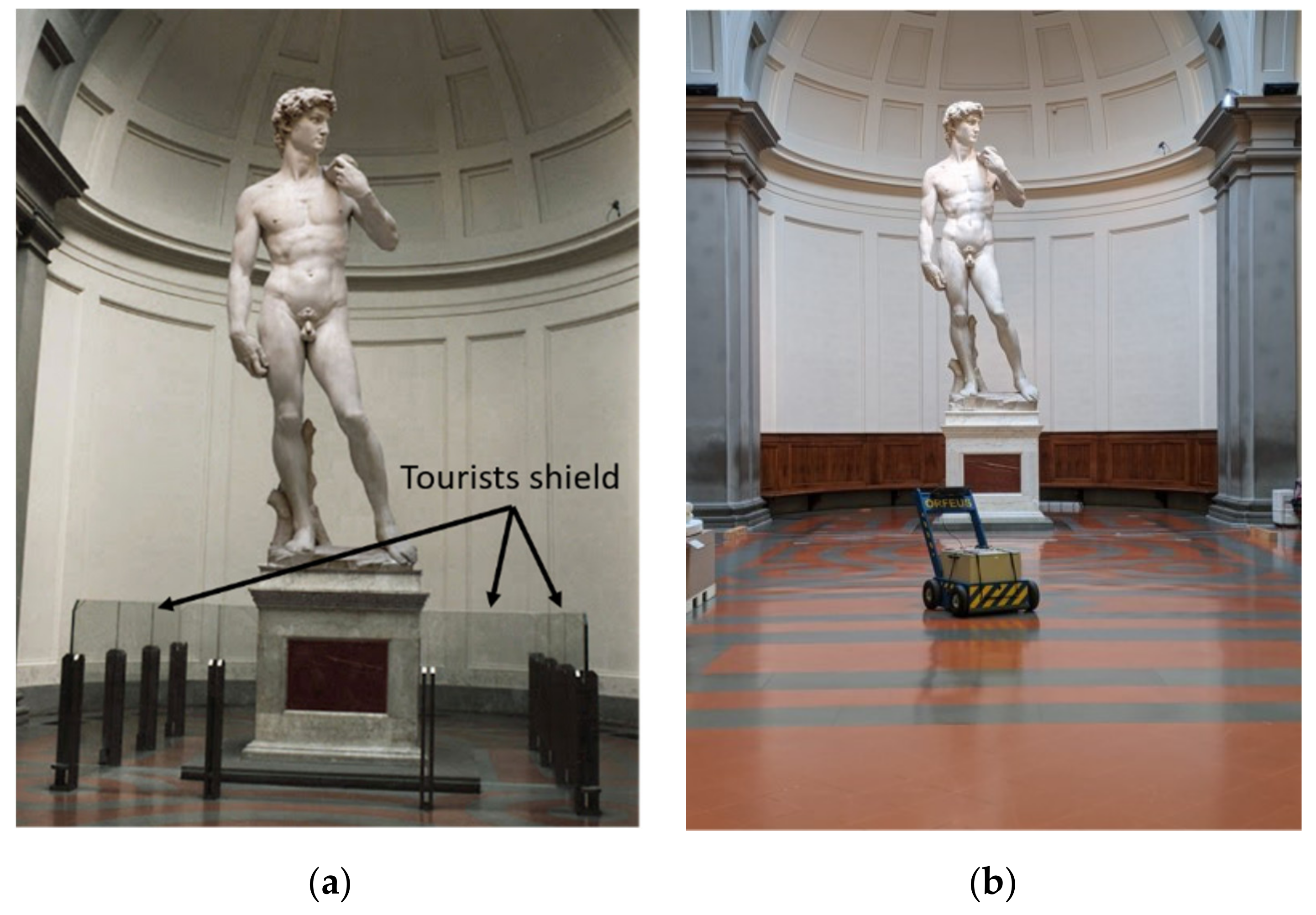
2.3. The GPR Survey
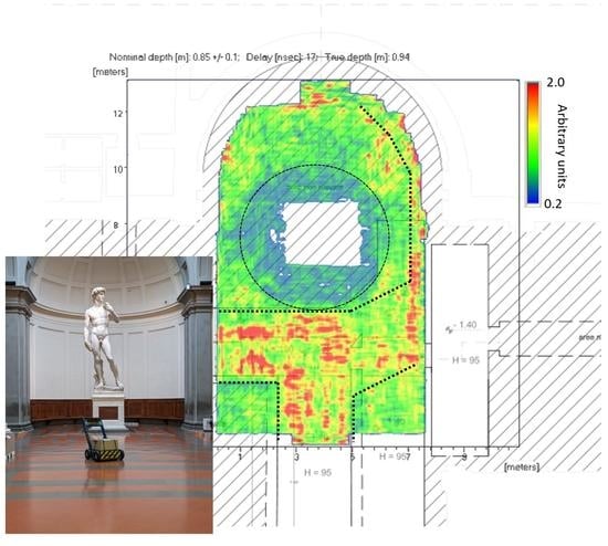
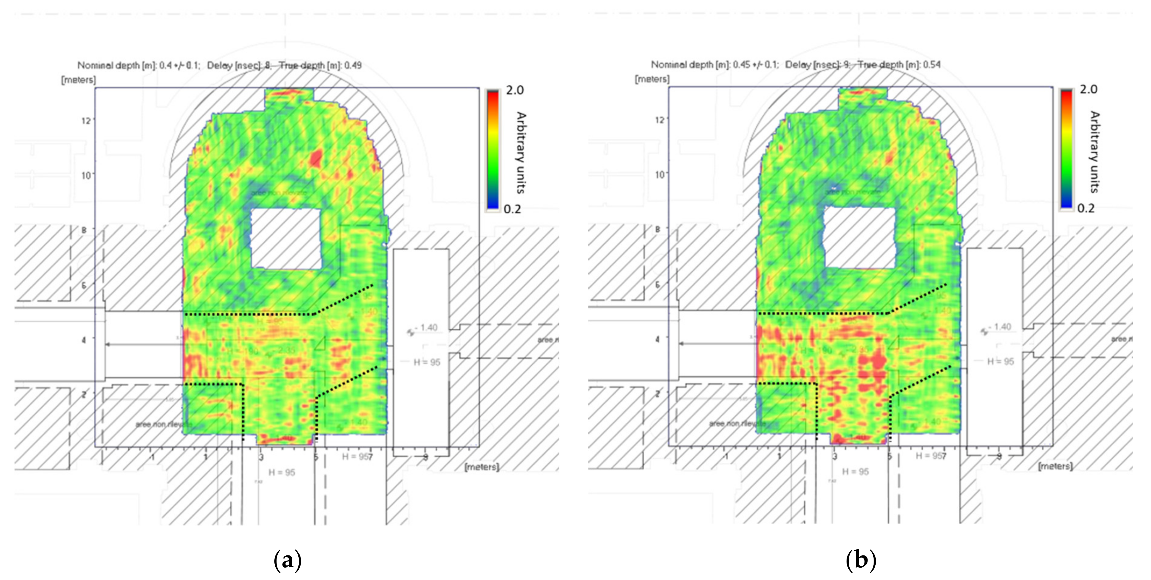
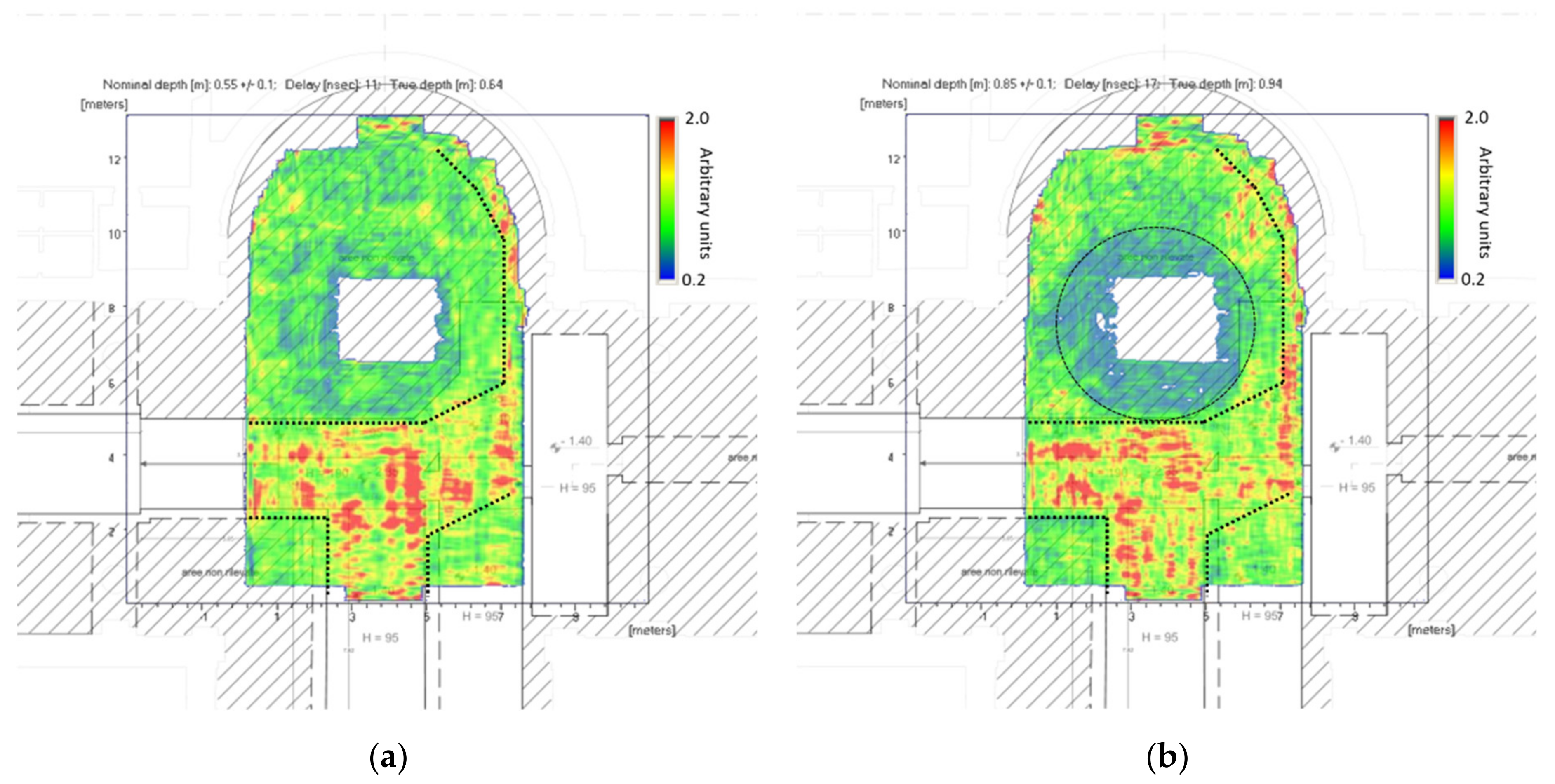
3. Results
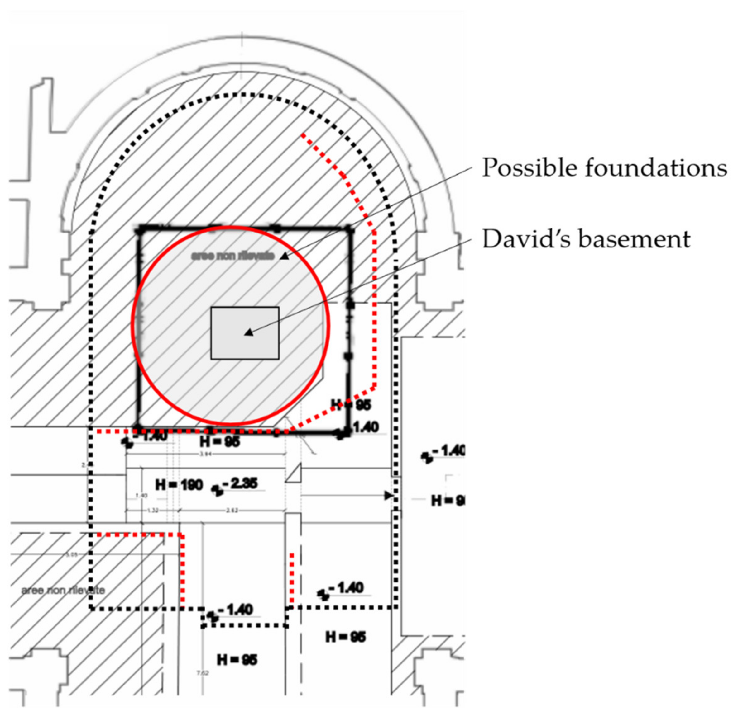
4. Discussion
5. Conclusions
Author Contributions
Funding
Institutional Review Board Statement
Informed Consent Statement
Data Availability Statement
Conflicts of Interest
References
- Giorgianni, G. (Ed.) La Valutazione del Rischio Sismico nel Complesso della GALLERIA dell’Accademia di Firenze: Un’Applicazione Sperimentale delle “Linee Guida MiBACT per la Valutazione e Riduzione del Rischio Sismico del Patrimonio Culturale (2009–2013); Altralinea Edizioni: Firenze, Italy, 2018. (In Italian) [Google Scholar]
- Borri, A. La Stabilità delle Grandi Statue: Il David di Michelangelo; DEI: Rome, Italy, 2005. (In Italian) [Google Scholar]
- Borri, A.; Grazini, A. Diagnostic analysis of the lesions and stability of Michelangelo’s David. J. Cult. Herit. 2006, 7, 273–285. [Google Scholar] [CrossRef]
- Corti, G.; Costagliola, P.; Bonini, M.; Benvenuti, M.; Pecchioni, E.; Vaiani, A.; Landucci, F. Modelling the failure mechanisms of Michelangelo’s David through small-scale centrifuge experiments. J. Cult. Herit. 2015, 16, 26–31. [Google Scholar] [CrossRef]
- Pieraccini, M.; Betti, M.; Forcellini, D.; Dei, D.; Papi, F.; Bartoli, G.; Facchini, L.; Corazzi, R.; Kovacevic, V.C. Radar detection of pedestrian-induced vibrations on Michelangelo’s David. PLoS ONE 2017, 12, e0174480. [Google Scholar] [CrossRef] [PubMed] [Green Version]
- Borri, A.; Faella, G.; Ferri, L.; Guadagnuolo, M. Indagini Georadar sul Basamento del David di Michelangelo; La scuola di Pitagora: Napoli, Italy, 2010. (In Italian) [Google Scholar]
- «Home—Firenze BAP». Available online: http://www.sbap-fi.beniculturali.it/ (accessed on 3 February 2021).
- Grandjean, G.; Gourry, J.C.; Bitri, A. Evaluation of GPR techniques for civil-engineering applications: Study on a test site. J. Appl. Geophys. 2000, 45, 141–156. [Google Scholar] [CrossRef]
- Orlando, L.; Slob, E. Using multicomponent GPR to monitor cracks in a historical building. J. Appl. Geophys. 2009, 67, 327–334. [Google Scholar] [CrossRef]
- Kilic, G. Using advanced NDT for historic buildings: Towards an integrated multidisciplinary health assessment strategy. J. Cult. Herit. 2015, 16, 526–535. [Google Scholar] [CrossRef]
- Perez-Gracia, V.; Canas, J.A.; Pujades, L.G.; Clapés, J.; Caselles, O.; Garcıa, F.; Osorio, R. GPR survey to confirm the location of ancient structures under the Valencian Cathedral (Spain). J. Appl. Geophys. 2000, 43, 167–174. [Google Scholar] [CrossRef]
- Perez-Gracia, V.; Caselles, O.; Clapes, J. Ground penetrating radar assessment of historical buildings: The study of the roofs, columns and ground of Santa Maria del Mar, in Barcelona. In Proceedings of the IEEE 15th Mediterranean Microwave Symposium (MMS), Lecce, Italy, 30 November–2 December 2015. [Google Scholar]
- Pieraccini, M.; Miccinesi, L.; Conti, A.; Fiorini, L.; Tucci, G.; Pieri, I.; Corazzini, S. Integration of GPR and TLS for investigating the floor of the “Salone dei Cinquecento” in Palazzo Vecchio, Florence, Italy. Archaeol. Prospect. 2020, 1–6. [Google Scholar] [CrossRef]
- Pieraccini, M. Noise performance comparison between continuous wave and stroboscopic pulse ground penetrating radar. IEEE Geosci. Remote Sens. Lett. 2018, 15, 222–226. [Google Scholar] [CrossRef]
- Hamran, S.E.; Gjessing, D.T.; Hjelmstad, J.; Aarholt, E. Ground penetrating synthetic pulse radar: Dynamic range and modes of operation. J. Appl. Geophys. 1995, 33, 7–14. [Google Scholar] [CrossRef]
- Parrini, F.; Pieraccini, M.; Grazzini, G.; Spinetti, A.; Macaluso, G.; De Pasquale, G.; Testa, C. ORFEUS GPR: A very large bandwidth and high dynamic range CWSF radar. In Proceedings of the XIII International Conference on Ground Penetrating Radar, Lecce, Italy, 21–25 June 2010. [Google Scholar]
- Pieraccini, M.; Capineri, L.; Falorni, P.; Devis, D. GPR investigation of “Fortezza da Basso” (Lower Fortress) in Florence, Italy. In Proceedings of the 16th International Conference on Ground Penetrating Radar (GPR), Hong Kong, China, 13–16 June 2016. [Google Scholar]
- Pieraccini, M.; Miccinesi, L.; Canizares, H.G. Critical verification of the underground cartography of the municipality using a high performance Ground Penetrating Radar. In Proceedings of the 10th International Workshop on Advanced Ground Penetrating Radar, The Hague, The Netherlands, 8–12 September 2019. [Google Scholar]


Publisher’s Note: MDPI stays neutral with regard to jurisdictional claims in published maps and institutional affiliations. |
© 2021 by the authors. Licensee MDPI, Basel, Switzerland. This article is an open access article distributed under the terms and conditions of the Creative Commons Attribution (CC BY) license (http://creativecommons.org/licenses/by/4.0/).
Share and Cite
Miccinesi, L.; Beni, A.; Monchetti, S.; Betti, M.; Borri, C.; Pieraccini, M. Ground Penetrating Radar Survey of the Floor of the Accademia Gallery (Florence, Italy). Remote Sens. 2021, 13, 1273. https://doi.org/10.3390/rs13071273
Miccinesi L, Beni A, Monchetti S, Betti M, Borri C, Pieraccini M. Ground Penetrating Radar Survey of the Floor of the Accademia Gallery (Florence, Italy). Remote Sensing. 2021; 13(7):1273. https://doi.org/10.3390/rs13071273
Chicago/Turabian StyleMiccinesi, Lapo, Alessandra Beni, Silvia Monchetti, Michele Betti, Claudio Borri, and Massimiliano Pieraccini. 2021. "Ground Penetrating Radar Survey of the Floor of the Accademia Gallery (Florence, Italy)" Remote Sensing 13, no. 7: 1273. https://doi.org/10.3390/rs13071273
APA StyleMiccinesi, L., Beni, A., Monchetti, S., Betti, M., Borri, C., & Pieraccini, M. (2021). Ground Penetrating Radar Survey of the Floor of the Accademia Gallery (Florence, Italy). Remote Sensing, 13(7), 1273. https://doi.org/10.3390/rs13071273