
Improving Boundary Constraint of Probability Integral Method in SBAS-InSAR for Deformation Monitoring in Mining Areas

 ,
,
Abstract
:
1. Introduction
2. Materials and Methods
2.1. SBAS-InSAR Technology
2.2. The Probability Integral Method (PIM)
2.3. Parameter Inversion with PSO
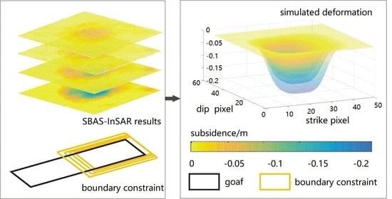
2.4. Boundary Constraints
3. Results
3.1. Condition of Research Zone
3.2. SBAS-InSAR Processing
3.3. Proposed Processing
3.4. Validation
4. Discussion
4.1. Comparison between the Proposed Method and the Traditional PIM
4.2. Comparison between the Proposed Method and the SBAS-InSAR Results
4.3. Influence of Complex Geological Conditions and InSAR Geometry
5. Conclusions
Author Contributions
Funding
Conflicts of Interest
References
- Ferretti, A.; Prati, C.; Rocca, F. Multibaseline InSAR DEM reconstruction: The wavelet approach. IEEE Trans. Geosci. Remote Sens. 1999, 37, 705–715. [Google Scholar] [CrossRef]
- Ferretti, A.; Prati, C. Nonlinear subsidence rate estimation using permanent scatterers in differential SAR interferometry. IEEE Trans. Geosci. Remote Sens. 2000, 38, 2202–2212. [Google Scholar] [CrossRef] [Green Version]
- Berardino, P.; Fornaro, G.; Lanari, R.; Sansosti, E. A New Algorithm for Surface Deformation Monitoring Based on Small Baseline Differential SAR Interferograms. IEEE Trans. Geosci. Remote Sens. 2002, 40, 2375–2383. [Google Scholar] [CrossRef] [Green Version]
- Li, P.; Tan, Z.; Yan, L. A Shaft Pillar Mining Subsidence Calculation Using Both Probability Integral Method and Numerical Simulation. Comput. Modeling Eng. Sci. 2018, 117, 231–249. [Google Scholar] [CrossRef]
- Bock, S.H. New open-source ANSYS-SolidWorks-FLAC3D geometry conversion programs. J. Sustain. Min. 2015, 14, 124–132. [Google Scholar] [CrossRef] [Green Version]
- Xia, Y.; Wang, Y.; In, S.A.R. PIM-Based Inclined Goaf Determination for Illegal Mining Detection. Remote Sens. 2020, 12, 3884. [Google Scholar] [CrossRef]
- Xu, B.R.N.; Mei, G. An equivalent discontinuous modeling method of jointed rock masses for DEM simulation of mining-induced rock movements. Int. J. Rock Mech. Min. Sci. 2018, 108, 1–14. [Google Scholar]
- Pereira, S.P.; Costa, J.F.C.L.; Salvadoretti, P.; Koppe, J. Mining simulation for room and pillar coal operation. Rem Rev. Esc. De Minas 2010, 63, 581–589. [Google Scholar] [CrossRef] [Green Version]
- Yang, Z.F.; Li, Z.W.; Zhu, J.J.; Hu, J.; Wang, Y.J.; Chen, G.L. InSAR-Based Model Parameter Estimation of Probability Integral Method and Its Application for Predicting Mining-Induced Horizontal and Vertical Displacements. IEEE Trans. Geosci. Remote Sens. 2016, 54, 4818–4832. [Google Scholar] [CrossRef]
- Fan, H.D.; Cheng, D.; Deng, K.Z.; Chen, B.Q.; Zhu, C.G. Subsidence monitoring using D-InSAR and probability integral prediction modelling in deep mining areas. Surv. Rev. 2015, 345, 438–445. [Google Scholar] [CrossRef]
- Tan, X.; Song, B.; Bo, H.; Li, Y.; Wang, M.; Lu, G. Extraction of Irregularly Shaped Coal Mining Area Induced Ground Subsidence Prediction Based on Probability Integral Method. Appl. Sci. 2020, 10, 6623. [Google Scholar] [CrossRef]
- Karamvasis, K.; Karathanassi, V. Performance Analysis of Open Source Time Series InSAR Methods for Deformation Monitoring over a Broader Mining Region. Remote Sens. 2020, 12, 1380. [Google Scholar] [CrossRef]
- Chen, Y.; Tong, Y.; Tan, K. Coal Mining Deformation Monitoring Using SBAS-InSAR and Offset Tracking: A Case Study of Yu County, China. IEEE J. Sel. Top. Appl. Earth Obs. Remote Sens. 2020, 13, 6077–6087. [Google Scholar] [CrossRef]
- Zhang, L.; Cai, X.; Wang, Y.; Wei, W.; Liu, B.; Jia, S.; Pang, T.; Bai, F.; Wei, Z. Long-term ground multi-level deformation fusion and analysis based on a combination of deformation prior fusion model and OTD-InSAR for longwall mining activity. Measurement 2020, 161, 107911. [Google Scholar] [CrossRef]
- Zhang, L.; Mao, Q.; Li, Q.; Zhang, P. An accuracy-improvement method for GPS/INS kinematic levelling for use in linear engineering surveying projects. Measurement 2014, 54, 22–30. [Google Scholar] [CrossRef]
- Fan, H.; Lu, L.; Yao, Y. Method Combining Probability Integration Model and a Small Baseline Subset for Time Series Monitoring of Mining Subsidence. Remote Sens. 2018, 10, 1444. [Google Scholar] [CrossRef] [Green Version]
- Yang, Z.F.; Li, Z.W.; Zhu, J.J.; Preusse, A.; Yi, H.W.; Wang, Y.J.; Papst, M. An Extension of the InSAR-Based Probability Integral Method and Its Application for Predicting 3-D Mining-Induced Displacements Under Different Extraction Conditions. IEEE Trans. Geosci. Remote Sens. 2017, 55, 3835–3845. [Google Scholar] [CrossRef]
- Yang, Z.; Li, Z.; Zhu, J.; Yi, H.; Feng, G.; Hu, J.; Wu, L.; Preusse, A.; Wang, Y.J.; Papst, M. Locating and defining underground goaf caused by coal mining from space-borne SAR interferometry. ISPRS J. Photogramm. Remote Sens. 2018, 135, 112–126. [Google Scholar] [CrossRef]
- Zheng, M.; Deng, K.; Du, S.; Jie, L.; Feng, J. Joint Probability Integral Method and TCPInSAR for Monitoring Mining Time-Series Deformation. J. Indian Soc. Remote Sens. 2018, 47, 63–65. [Google Scholar] [CrossRef]
- Du, S.; Wang, Y.; Zheng, M.; Zhou, D.; Xia, Y. Goaf Locating Based on InSAR and Probability Integration Method. Remote Sens. 2019, 11, 812. [Google Scholar] [CrossRef] [Green Version]
- Wang, L.; Deng, K.; Zheng, M. Research on ground deformation monitoring method in mining areas using the probability integral model fusion D-InSAR, sub-band InSAR and offset-tracking. Int. J. Appl. Earth Obs. Geoinf. 2019, 85, 101981. [Google Scholar] [CrossRef]
- Pritchard, M.E.; Simons, M. A satellite geodetic survey of large-scale deformation of volcanic centres in the central Andes. Nature 2002, 418, 167–171. [Google Scholar] [CrossRef] [PubMed]
- Hanssen, R.F. Radar Interferometry Data Interpretation and Error Analysis. IEEE 2001, 96–98. [Google Scholar]
- Sun, Q.; Zhang, L.; Hu, J.; Ding, X.; Li, Z.; Zhu, J. Characterizing sudden geo-hazards in mountainous areas by D-InSAR with an enhancement of topographic error correction. Nat. Hazards 2015, 75, 2343–2356. [Google Scholar] [CrossRef]
- Hong, S.H.; Wdowinski, S.; Kim, S.W.; Won, J.S. Multi-temporal monitoring of wetland water levels in the Florida everglades using interferometric synthetic aperture radar (InSAR). Remote Sens. Environ. 2010, 114, 2436–2447. [Google Scholar] [CrossRef]
- Yu, C.; Li, Z.; Penna, N.T. Interferometric synthetic aperture radar atmospheric correction using a GPS-based iterative tropospheric decomposition model. Remote Sens. Environ. 2018, 204, 109–121. [Google Scholar] [CrossRef]
- Xinpeng, D.; Kan, W.; Dahe, H.; Liang, L.; Dawei, Z. Combining differential SAR interferometry and the probability integral method for three-dimensional deformation monitoring of mining areas. Int. J. Remote Sens. 2016, 37, 5196–5212. [Google Scholar]
- Yang, Z.; Xu, B.; Li, Z.; Wu, L.; Zhu, J. Prediction of Mining-Induced Kinematic 3-D Displacements from InSAR Using a Weibull Model and a Kalman Filter. IEEE Trans. Geosci. Remote Sens. 2021, 99, 1–12. [Google Scholar]
- Yang, Z.; Li, Z.; Zhu, J.; Preusse, A.; Hu, J.; Feng, G.; Wang, Y.; Papst, M. An InSAR-Based Temporal Probability Integral Method and its Application for Predicting Mining-Induced Dynamic Deformations and Assessing Progressive Damage to Surface Buildings. IEEE J. Sel. Top. Appl. Earth Obs. Remote Sens. 2018, 2, 1–13. [Google Scholar] [CrossRef]
- Kennedy, J. Particle swarm optimization. Proc. IEEE Int. Conf. Neural Netw. 2011, 4, 1942–1948. [Google Scholar]
- Poli, R.; Kennedy, J.; Blackwell, T. Particle swarm optimization. Swarm Intell. 2007, 1, 1942–1948. [Google Scholar] [CrossRef]
- Das, A.; Chakrabarti, B.K. Quantum Annealing and Related Optimization Methods; Springer: Berlin/Heidelberg, Germany, 2005. [Google Scholar]
- Yihdego, Y.; Paffard, A. Predicting Open Pit Mine Inflow and Recovery Depth in the Durvuljin soum, Zavkhan Province, Mongolia. Mine Water Environ. 2016, 36, 114–123. [Google Scholar] [CrossRef]
- Chi, S.; Wang, L.; Yu, X.; Fang, X.; Jiang, C. Research on prediction model of mining subsidence in thick unconsolidated layer mining area. IEEE Access 2021, 99, 11. [Google Scholar]
- Liu, H.; Zhang, M.; Su, L.; Chen, X.; Sun, A. A boundary model of terrain reconstruction in a coal-mining subsidence waterlogged area. Environ. Earth Sci 2021, 80, 187. [Google Scholar] [CrossRef]
- Zhu, X.; Guo, G.; Hui, L.; Yang, X. Surface subsidence prediction method of backfill-strip mining in coal mining. Bull. Eng. Geol. Environ. 2019, 78, 1–14. [Google Scholar] [CrossRef]
- Casu, F.; Manconi, A.; Pepe, A.; Lanari, R. Deformation Time-Series Generation in Areas Characterized by Large Displacement Dynamics: The SAR Amplitude Pixel-Offset SBAS Technique. IEEE Trans. Geosci. Remote Sens. 2011, 49, 2752–2763. [Google Scholar] [CrossRef]
- Zhao, C.; Zhong, L.U.; Zhang, Q. Time-series deformation monitoring over mining regions with SAR intensity-based offset measurements. Remote Sens. Lett. 2013, 4, 436–445. [Google Scholar] [CrossRef]
- He, K.; Guo, L.; Guo, Y.; Luo, H.; Liang, Y. Research on the effects of coal mining on the karst hydrogeological environment in Jiaozuo mining area, China. Environ. Geol. 2019, 78, 434. [Google Scholar]


| Monitoring Methods | Monitoring Type | Characteristic | Disadvantage | Precision |
|---|---|---|---|---|
| Leveling | Point monitoring | Direct monitoring | Time consuming | mm level [15] |
| GPS | Point monitoring | Direct monitoring | High cost and low precision | cm level (GPS/INS) [15] |
| D-InSAR | Area monitoring | Indirect monitoring | Low precision | cm level [10] |
| TS-InSAR | Area monitoring | Indirect monitoring | More data and more cost | mm level [12] |
| PIM | Simulation monitoring | Numerical simulation | Need local survey data | 2~3 cm [10] |
| Known Parameters | Analytical Range | ||
|---|---|---|---|
| Parameter | Value | Parameter | Range |
| m | 5.74 m | q | 0.1–0.9 |
| −10° | B | 0.2–0.4 | |
| 33.79° | 0–10 m | ||
| 43° | 0–30 m | ||
| 13° | 0–10 m | ||
| H | 547.9–553.6464 m | 0–100 m | |
| 699.57 m | |||
| L | 135.56 m | ||
Publisher’s Note: MDPI stays neutral with regard to jurisdictional claims in published maps and institutional affiliations. |
© 2021 by the authors. Licensee MDPI, Basel, Switzerland. This article is an open access article distributed under the terms and conditions of the Creative Commons Attribution (CC BY) license (https://creativecommons.org/licenses/by/4.0/).
Share and Cite
Shi, M.; Yang, H.; Wang, B.; Peng, J.; Gao, Z.; Zhang, B. Improving Boundary Constraint of Probability Integral Method in SBAS-InSAR for Deformation Monitoring in Mining Areas. Remote Sens. 2021, 13, 1497. https://doi.org/10.3390/rs13081497
Shi M, Yang H, Wang B, Peng J, Gao Z, Zhang B. Improving Boundary Constraint of Probability Integral Method in SBAS-InSAR for Deformation Monitoring in Mining Areas. Remote Sensing. 2021; 13(8):1497. https://doi.org/10.3390/rs13081497
Chicago/Turabian StyleShi, Mengyao, Honglei Yang, Baocun Wang, Junhuan Peng, Zhouzheng Gao, and Bin Zhang. 2021. "Improving Boundary Constraint of Probability Integral Method in SBAS-InSAR for Deformation Monitoring in Mining Areas" Remote Sensing 13, no. 8: 1497. https://doi.org/10.3390/rs13081497