1. Introduction
Moving load-based damage detection methods have attracted significant attention recently, as they have several advantages over other damage detection methods, such as [
1,
2,
3,
4,
5,
6,
7,
8,
9,
10]:
- (1)
There are no traffic interruptions;
- (2)
Analysis is performed under operational environment conditions;
- (3)
Analysis is performed continuously;
- (4)
There is no need for exceptional experimental arrangements or techniques;
- (5)
The number of sensors and amount of expense is reduced;
- (6)
There is the ability for excitation of structural vibrations with a large amplitude and high signal-to-noise ratio.
The dynamic interaction force between vehicles and road surface can be intensified by structural damage, road surface roughness and vehicle speed. Therefore, it is of high importance to simultaneously identify moving loads and structural damage while considering road surface roughness. Although there have been extensive attempts to identify moving loads with known structural parameters [
11,
12,
13,
14,
15,
16], or to identify structural parameters subject to non-moving loads, moving masses or knowing moving loads, their simultaneous identification has not been studied enough [
17,
18,
19,
20,
21,
22].
In reality, unknown damages and unknown moving loads can exist together, influencing the response of the system. To address this problem, different algorithms have been developed using output only. Hoshiya and Maruyama [
23] applied a weighted global iteration procedure to simultaneously identify moving loads and modal parameters of a simply supported beam. Extended Kalman filter was used in their method.
Zhu and Law [
24] presented a method based on displacement measurements to simultaneously identify moving loads and crack damage. They verified the method numerically for a simply supported beam considering measurement noise, road roughness, and the number of beam elements in the finite element model. Results showed that the method is sensitive to road roughness. This method has not been verified for a multiple span bridge or experimentally, and it requires a full-sensor placement. This method later was extended by Law and Li [
25] and numerically verified by a three-span pre-stressed concrete box-section bridge under the action of a two-axle three-dimensional vehicle. The results of this comprehensive study have indicated that a sufficient number of sensors are needed, and that the accuracy of identified moving loads can greatly affect the accuracy of damage detection.
Lu and Law [
17] proposed a method based on the sensitivity of dynamic response to simultaneously identify moving loads and damage. Sinusoidal and impulsive forces with known locations were studied. The method was verified numerically by a single-span simply supported bean and a two-span continuous concrete beam as well as experimentally by a simply supported steel beam. Numerical results show no false alarm in any other adjacent undamaged elements, however, in experimental results there was considerable false identification of damage in adjacent elements. Zhang et al. [
18,
19] presented a method based on the Virtual Distortion Method for simultaneous identification of moving mass and structural damage. In this method a couple of masses are moving on a flat bridge at constant speeds. In these studies, the vehicle model is not considered as an excitation source and the effect of road surface roughness is not considered.
Later, Zhang et al. [
26] presented a method for simultaneous identification of moving vehicles and bridge damage considering road surface roughness. In this study, the vehicle parameters and structural damage were treated as optimization variables. The method was numerically verified by a 200 m long three-span bridge, and the robustness of the method for model error and measurement noise was tested. However, the effects of different uncertainties such as different levels of road roughness, vehicle speed, damage location and extension, as well as computation time were not discussed.
Sun and Betti [
21] presented a hybrid artificial bee colony strategy to simultaneously identify structural parameters and, when possible, dynamic input time histories from incomplete sets of acceleration measurements. The method has been numerically verified by three types of frames. In this method, the non-moving load is considered as an excitation source, and it is highly sensitive to measurement noise.
Feng et al. [
27] proposed a method of utilizing a limited number of sensors to simultaneously identify bridge structural parameters and vehicle axle loads via an iterative parametric optimization process. The study applied a Bayesian inference-based regularization approach in an attempt to solve the ill-posed least squares problem for the unknown vehicle axle loads. Yet while this method was numerically verified over different vehicle speeds and levels of noise, both for a simply supported bridge and a three-span continuous bridge, the effect of roughness was not directly considered, and the method showed load identification errors over mid supports.
Abbasnia et al. [
28] developed a sensitivity-based damage detection method referred to as Adjoint Variable Method (AVM) to simultaneously identify moving loads and structural damage. The effectiveness of the proposed method is numerically illustrated by a two-span continuous girder and a plate. The method is sensitive to noise greater than 1.4% and the effect of road roughness is not explored. Obrien et al. [
29] proposed a method for damage detection based on moving force identification. A two-dimensional vehicle-bridge interaction model is used for numerical verification. Both strains and deflections have been studied as measured responses. Results indicate that strain measurements are effective only when the sensor is close to the damage zone. Furthermore, the method is sensitive to damage location, and it can be identified well only if it is close to the center of the beam.
Jayalakshmi et al. [
22] presented an approach to simultaneously identify structural parameters and non-moving dynamic forces and verified them numerically by use of three examples of a simply supported beam, a building, and a truss bridge. This approach is based on a newly developed dynamic hybrid adaptive firefly algorithm (DHAFA) and a modified version of Tikhonov regularization plus the explicit form of the Newmark-β method. There are many limitations to reaching acceptable results by this method such as:
- (1)
Sensors should be available at the location of dynamic forces,
- (2)
One input force-time history should be known,
- (3)
The known load should be in the range of 0.6 times to 1.5 times of the unknown forces. In practice however, these assumptions are not so simple to apply. Wang et al. [
30] developed a method for simultaneous identification of the load and unknown parameters where the excitation source is non-moving.
Most of the studies of simultaneous identification of damage and load are for non-moving loads, and those which are for structures under moving loads are not investigated comprehensively for different uncertainties or are not verified experimentally. Furthermore, moving load identification in existing studies is commonly formulated in state space, which is sensitive to discretization and sampling rate [
11,
12,
13,
14,
15,
16]. Liu et al. [
31] developed and verified the explicit form of the Newmark-β method for a force identification of a full structure under a non-moving load. It is shown to be superior to the state space method. Later, the authors of this paper developed the method for moving load identification for bridge structures and verified the results numerically and experimentally, which are published in the reference [
32].
This project is believed to be among the few studies on simultaneous identification of moving load and structural damage considering factors such as measurement noise, road surface roughness, sampling frequency, sensor placement, number of spans, number of elements in the finite element model of the bridge, and the vehicle speed. Furthermore, results are verified by numerical and experimental studies. In this study, strain and acceleration measurements are used as inputs. There is no need for complete measurements at interface nodes as well as no need for interface force measurements. The moving vehicle is unknown and only its location and speed is needed to be known in advance.
In this Paper, a review of dynamics of the vehicle-bridge interaction system and moving load identification based on the explicit form of Newmark-β method is presented in
Section 2 and
Section 3, in order.
Section 4 describes the element damage index, sensitivities of dynamic responses, and how it can be used to detect damage. The iterative identification procedure to simultaneously identify moving loads and structural parameters is also described in this section. In
Section 5, the numerical analyses of a single-span simply supported bridge is conducted to demonstrate the accuracy and efficiency of the proposed method. The effects of measurement noise, sensor placement, damage location and extension, vehicle speed, and road surface roughness on the accuracy of the method are investigated. In
Section 6, a two-span continuous bridge is studied to check if mid-supports affect the accuracy of the method.
Section 7, delivers an experimental study in the laboratory to verify the proposed techniques experimentally. The set up mainly includes a 3 m single-span simply supported beam excited by a four-wheel car being pulled through the beam by an electronic motor. The advantages and limitations of the proposed method are summarized in
Section 8.
3. Moving Load Identification Formula Based on the Explicit Form of Newmark-β Method
The authors of this paper previously developed the explicit form of Newmark-β method to identify moving loads on an intact bridge structure [
32]. As a result of the developed method, Equation (1) can be represented as below:
where
where
t shows time instant,
shows time interval, and
Vector
denoting the output of the structural system can be presented as follows:
where
are the influence matrices which are multiplied by the related measured responses,
is the dimension of the measured responses and
is the number of degrees of freedom of the structure.
Letting
, Equation (4) can be represented as follows:
Assuming zero initial conditions of the structure, Equation (5) can then be rewritten in the matrix convolution form, in the time duration from
to
, as the following equation:
where
is the number of time instants and
where
In the above equations,
is the assembled measured acceleration vector,
is the assembled unknown force vector, and
is known as the Hankel matrix of the bridge consisting of the system Markov parameters. It should be highlighted that
is time-dependent and should be updated at each time step. Provided that
can be identified in Equation (6),
can be determined from measured
. More details in this regards can be found in reference [
32].
5. Numerical Example I: Simply Supported Single Span Bridge
To demonstrate the applicability and effectiveness of the proposed algorithm for simultaneous identification of moving loads and structural damage, in this section a simply supported single-span bridge with 30 m length subjected to the moving vehicle is considered.
Table 1 and
Table 2 list the parameter values of the vehicle and bridge subsystems, respectively, which are estimated according to the reference [
34]. The first five natural frequencies for the simply supported bridge are 3.9, 15.6, 35.1, 62.5, and 97.6 Hz, and the first four natural frequencies of the vehicle are 1.63, 2.29, 10.35, and 15.1 Hz, respectively.
The efficiency of the proposed method subject to different damage scenarios, sensor placements, road surface roughness levels, vehicle speeds, and measurement noise levels have been investigated. The time step is 0.005 s in the simulations. The finite element model (FEM) of the bridge includes 15 Euler-Bernoulli beam elements, with 16 nodes. Each node has two degrees of freedom, rotation and vertical. Other assumptions of this numerical study are explained in
Section 5.1.
In this numerical study, measured accelerations have been simulated by a forward analysis of the vehicle-bridge interaction system using the explicit form of Newmark-β method. However, in practice, no prior knowledge of the road roughness and vehicle information is required to apply this method. Only the axle spacing and vehicle speed are needed, which can both be easily obtained by the optical sensors installed at the entry and exit locations of the bridge.
The percentage error of identified loads (I.L.), reconstructed response (Rec. Acc.), and damage identification error (D.I.), as well as the total time and the number of iterations (N.I.) to converge are investigated. The results are presented in
Section 5.1 and discussed in
Section 5.2.
The system processor used in this study is an Intel® Core ™ i7-4790 CPU @ 3.60 GHz and the installed memory (RAM) is 32.0 GB. MATLAB R2019B with company name of MathWorks is used for numerical analysis.
5.1. Identification Results
5.1.1. Effect of Damage Type
In this section, a detailed study of the effects of damage location and its extension on the accuracy of the proposed method is carried out. Seventeen different damage scenarios are investigated, as shown in
Table 3. The vehicle moves over the bridge at speed 40 m/s, and the road surface roughness is assumed to be “A”. Full sensor placement is used. Noise is not considered here. Convergence tolerance is applied as 10
−6. Scenarios 16 and 17, including two damaged elements, are intended to investigate the efficiency of the method when there are multiple damaged elements. Results can be found in
Table 4, and
Figure 1.
5.1.2. Effect of Sensor Placements
In this section, the effect of five different sensor placements have been investigated (
Table 5). Sensors are approximately equally spaced. The vehicle moves over the bridge at the speed of 40 m/s. The road surface roughness is assumed to be “A”. Damage scenario #16 is applied here. Noise is not considered, and convergence tolerance is applied as 10
−6. Identification results can be found in
Table 6 and
Figure 2.
5.1.3. Effect of Vehicle Speed and Road Surface Roughness
In this section, the effect of vehicle speed and road surface roughness is studied. Four different vehicle speeds, namely, 15 m/s, 20 m/s, 30 m/s, and 40 m/s, and three different classes of road roughness, namely, A, B, and C are considered. Noise is not considered here. Sensor placement S6 and damage scenario #16 have been applied. Convergence tolerance is applied as 10
−6. Identification results can be found in
Table 7 and
Figure 3,
Figure 4,
Figure 5 and
Figure 6. Most of the existing studies for simultaneous identification of moving loads and structural parameters have not investigated the effect of vehicle speed or road surface roughness [
18,
19,
26,
27,
28].
5.1.4. Effect of Measurement Noise
In this section, the effect of noise on the accuracy of the method is explored. To account for the effect of measurement noise, the calculated responses are polluted with white noise to simulate the polluted measurement as follows:
where
is a vector of polluted response,
is the vector of real responses,
represents noise level, and
is a standard normal distribution vector with zero mean and unit standard deviation. It is notable that the effect of noise is also explored by the experimental study in the lab, the results of which can be found out in
Section 7.
In this section, the road surface roughness is assumed to be “A” and the efficiency of the method at vehicle speed 40 m/s and three different noise levels (1%, 5%, and 10%) is studied. Sensor placement S6 is used and damage scenario #16 is applied. Identified results are presented in
Table 8,
Figure 7 and
Figure 8.
5.2. Results Discussion
In this section, the effects of the factors named above are discussed below.
5.2.1. Effect of Damage Type
Table 5 indicates that moving loads are identified with less than 1% error in all cases. In all damage scenarios, acceleration has been reconstructed with less than 0.2% error. Therefore, this method can be used to predict acceleration at nodes that are not accessible to be measured directly by accelerometers.
According to
Table 5 and
Figure 1, the damage identification error in all cases is less than 0.5%. Damaged elements are detected and quantified precisely. The identified stiffness reduction of all intact elements is very close to zero, which shows the accuracy of the simulation.
Results show that the method is robust and not sensitive to different damage locations and extensions. In the study by O’Brien et.al. [
29], the method is sensitive to damage location, and it can be identified well only if it is close to the centre of the beam.
5.2.2. Effect of Sensor Placement
Table 6 shows that all five cases of sensor placement are able to identify moving loads and structural parameters with less than 1% error and to reconstruct acceleration with less than 0.08% error. From this aspect, the method is superior to both the methods were proposed by Zhu and law [
24]—needing full sensor placement- and by O’Brien [
29]—effective only when the sensor is close to the damage zone.
Identified stiffness reduction by these sensor placements is shown in
Figure 2. Damage has been detected and quantified very precisely. Identified stiffness reduction in intact elements is very close to zero, demonstrating the accuracy of the simulation. Sensor placement S3 with the least number of sensors is associated with the most computation time. Here, considering computation time and the number of sensors, sensor placement S6 is the most effective one. However, in reality, there might be some limitations due to accessible locations or budget, then three or five sensors could be sufficient as well. Case S6 is used for further studies in this research.
5.2.3. Effect of Vehicle Speed and Road Surface Roughness
According to
Figure 3 and
Figure 4, loads are identified reasonably, even in the worst case of moving load identification- at speed 15 m/s and road roughness “C”. According to
Figure 5, at speeds of 20 m/s and above, the damage is detected and quantified very precisely at all road roughness levels. At speed 15 m/s, some of the intact elements are identified as damaged elements. This might be because the bridge is not excited enough at this speed. At all road roughness levels, computation time increases as speed decreases, reaching its maximum value when road roughness is “C” and speed is 15 m/s.
Figure 6, shows the predicted acceleration values at the mid-span point closely match the true time histories, showing the accuracy of the results.
5.2.4. Effect of Measurement Noise
According to
Table 8, the moving load identification errors at different measurement noise levels are in the same range, however, damage identification errors and reconstructed responses errors are considerably affected by adding to the measurement noise level. Identified moving loads at vehicle speed 40 m/s are shown in
Figure 7. Without noise, moving loads closely match the true loads, showing the accuracy of the method.
According to
Figure 8, without noise, damaged elements are detected correctly without false positives or negatives at other elements, or the false values are too small. Damage is quantified very close to 20% at both elements 8 and 10. At a 1% noise level, the damage identification result is very close to that without noise. With the increase in measurement noise, damaged elements are still detected correctly, and their extension is quantified close to true values; however, some false positives and negatives in other elements are arisen. The reason is that the damage identification technique studied here is based on moving load identification, which is affected by noise, especially at a 10% noise level.
In sum, the proposed method is very successful in identifying moving loads and it is not sensitive to damage type, sensor configuration, road roughness level, vehicle speed, and measurement noise. Furthermore, the method can properly identify the loads in entrance and exit of the bridge where other methods failed. When it comes to damage detection, at 0% noise, the method is not sensitive to the above factors and results are promising, however, the method is sensitive to noise more than 1% and the method should be used carefully.
8. Conclusions
A numerical and experimental study of simultaneous identification of moving loads and structural damage based on the explicit form of the Newmark-β method has been carried out. The Generalized Tikhonov regularization technique is used to solve the ill-posed problem and the GCV method is used to find the optimal parameter λ.
The method is numerically verified by a single-span simply supported beam and a two-span continuous beam. The effects of damage location, sensor placements, measurement noise, vehicle speeds, and road surface roughness on the accuracy of the method is investigated. Numerical results indicate that the method is able to detect all levels of damage with minimum three sensors, and it is not sensitive to the location of the sensors. The number and location of the sensors can be determined based on the accessibility of the locations, client budget and time. Moving loads and damages can be simultaneously identified at different speed and roughness levels, and higher accuracy is achieved when speed is higher than 15 m/s, which might be because of the stronger excitations. Measurement noise level more than 5% can affect the results and reduce the accuracy of damage detection. At 10% noise, there are false positives and negatives at other intact elements.
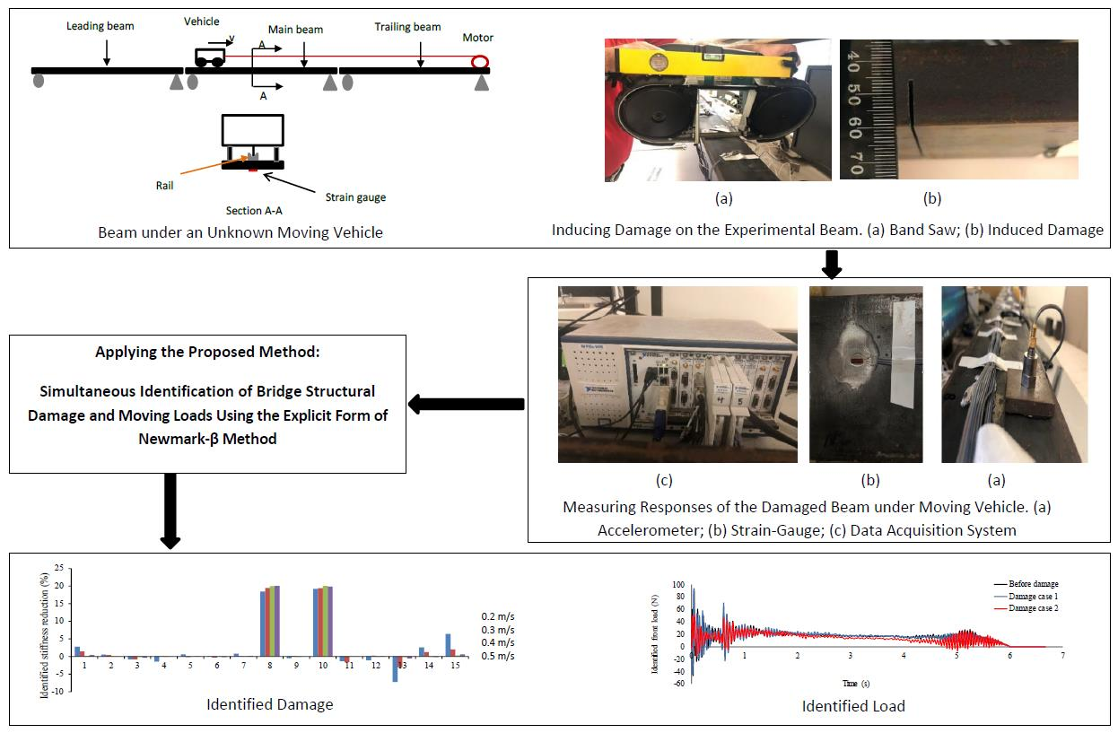
The method is experimentally verified by a 3m long steel simply supported bridge beam subject to a car model, pulled by an electrical motor along the bridge at a constant speed. Modal tests are conducted before damage and after damage to obtain the natural frequencies and finite element model updating are performed by minimizing the difference between experimental and numerical measurements. Two instances of local damage with different extents at two locations are induced at two stages.
Similar to the results concluded by the numerical studies, the accuracy of the experimental results is not affected at different levels of the vehicle speed and beam damage. According to the experimental results, the proposed method is reliable for identifying moving loads at different speed levels and sampling frequencies, before and after inducing the damages. When it comes to detecting and quantifying damaged elements through the simultaneous identification of moving loads and structural parameters, it can be seen that the false positives/negatives are identified for intact elements and there are large positives at boundary elements, resulting from the modeling errors of the boundary conditions.
This method will be further verified by a 3D modeling and field studies for more complex bridges such as cable stayed bridges. The proposed method is extended for sub-structural condition assessment of bridge structures under moving loads which will be presented in future publications.


