Technical Note

A Novel Weighted Amplitude Modulation (WAM) System for Ambiguity Suppression of Spaceborne Hybrid Quad-Pol SAR

1
Aerospace Information Research Institute, Chinese Academy of Sciences, Beijing 100190, China
2
School of Electronic, Electrical and Communication Engineering, University of Chinese Academy of Sciences, Beijing 100039, China
3
National Key Laboratory of Microwave Imaging Technology, Chinese Academy of Sciences, Beijing 100190, China
*
Author to whom correspondence should be addressed.
Remote Sens. 2022, 14(1), 155; https://doi.org/10.3390/rs14010155
Submission received: 6 December 2021 / Revised: 27 December 2021 / Accepted: 28 December 2021 / Published: 30 December 2021

Abstract

:
Quadrature-polarimetric synthetic aperture radar (quad-pol SAR) has extensive applications, including climate zones classification, extraction of surface roughness, soil moisture mapping, moving target indication, and rice mapping. Hybrid quad-pol SAR ameliorates the range ambiguity performance of conventional quad-pol SAR. However, the azimuth ambiguity of its cross-polarized (cross-pol) echo signals is serious, limiting the swath width of SAR. Therefore, this paper proposes a spaceborne weighted amplitude modulation (WAM) full-polarimetric (full-pol) SAR system, and it can suppress the azimuth ambiguity of hybrid quad-pol SAR. The performance boost of the azimuth ambiguity by the two imaging modes of the proposed SAR system is detailed and evaluated with the L-band system parameters. Moreover, the chirp scaling algorithm (CSA) is adopted to execute scene simulations for the two imaging modes. The results indicate that the proposed SAR system can effectively suppress the azimuth ambiguity of hybrid quad-pol SAR and verify the theoretical analysis.

Graphical Abstract

1. Introduction

Quadrature-polarimetric (quad-pol) synthetic aperture radar (SAR) has a dual-polarized antenna with twice as many degrees of freedom as a similar antenna with only one polarization channel [1,2,3]. The additional degrees of freedom of its transceivers can provide several advantages, including the enhancement of classification/discrimination between targets and clutters [4,5,6], polarization coding on transmit [7], measurement of scattering depolarization for remote sensing applications [8,9,10,11], and so on. Based on quad-pol SAR data, a lot of applications can be performed, including climate zones classification [12], extraction of surface roughness [13], soil moisture mapping [14], moving target indication [15], and rice mapping [16].
Conventional quad-pol SAR alternately transmits H- and V-polarized pulses, which are received by the H- and V-polarized antennas after scattering by targets, thereby obtaining the full scattering matrix of each pixel [17]. However, the range ambiguity of the cross-polarized (cross-pol) echo signals of conventional quad-pol SAR is serious [18], and the ionosphere produces a Faraday rotation effect on radar signals [19]. Besides, the lower the frequency of radar signals, the more obvious the Faraday rotation effect is. Therefore, a hybrid quad-pol SAR is proposed to eliminate the effect of Faraday rotation and reduce the range ambiguity of conventional quad-pol SAR by alternately emitting left- and right-circular polarization pulses [17]. However, the azimuth ambiguity of the cross-pol echoes of hybrid quad-pol SAR is bad, which also reduces the system performance of spaceborne SAR [18]. It can be obtained from above that both conventional and hybrid quad-pol SAR affect the system performance and reduce the swath width of SAR. Thus, it is necessary to design a spaceborne full-polarimetric (full-pol) SAR system with sound azimuth ambiguity performance.
In recent years, scholars have conducted some research on the azimuth ambiguity suppression of SAR images. In 2012, G. Krieger et al. analyzed the impacts of azimuth ambiguity on interferometry performance from the perspective of standard deviation and phase deviation of the interferometry phase [20]. After that, G. Di Martino proposed a method for the filtering of azimuth ambiguities on stripmap SAR images and named it AM&SF [21]. However, these methods focus on suppressing the azimuth ambiguity of SAR images, and cannot completely remove its influence. Since the azimuth ambiguity of the cross-pol echo signals of hybrid quad-pol SAR mainly comes from the influence of co-polarized (co-pol) echo signals [18], it can be suppressed by weighting the amplitude of co-pol signals [22]. Based on the concept, a spaceborne weighted amplitude modulation (WAM) full-pol SAR system is proposed to suppress the azimuth ambiguity of hybrid quad-pol SAR.
To further improve the system performance of spaceborne SAR, [23,24,25,26] we proposed the concept of multi-dimensional waveform coding, that is, the space-time coding of radar waveforms. The digital beamforming (DBF) is a common technique to suppress the ambiguity energy by the weighting of the received signals [27]. It can also be adopted to suppress the range ambiguity of quad-pol SAR. Specifically, the high-order range ambiguity is the large portion of the overall range ambiguity energy, and it can be filtered out by DBF in the pre-processing phase. Similar to DBF, the antenna pattern synthesis for range ambiguity suppression is another candidate [28]. Afterwards, the mature imaging algorithms, including back projection (BP) [29], chirp scaling (CS) [30] and extended chirp scaling (ECS) [31,32,33] can be used to image the echo signals. The proposed spaceborne WAM full-pol SAR system uses DBF to suppress range ambiguity. Then CSA is used to process the echo signals, and the high quality SAR images can be obtained. Based on the images, some applications, such as polarimetric SAR interferometry (Pol-InSAR) can be further realized, and a stable phase unwrapping algorithm [34] is necessary for Pol-InSAR.
The content is arranged as follows. Section 2 estimates the ambiguity performance of hybrid quad-pol SAR. Section 3 proposes a spaceborne WAM full-pol SAR system that can suppress the azimuth ambiguity of hybrid quad-pol SAR, and estimates the ambiguity performance of its two imaging modes by the L-band system parameters. Section 4 conducts scene simulations on the proposed SAR system, and this paper is closed by a conclusion in Section 5.

2. Hybrid Quad-Pol SAR

In hybrid quad-pol SAR the left- and right-circular polarization pulses are alternately emitted, and received by two orthogonal linear polarized antennas (e.g., H- and V-polarized antennas) at the same time after scattering by targets [17]. After that, the obtained full scattering matrixes are processed to obtain polarimetric SAR images, thereby implementing some missions, such as Pol-InSAR [18,34], climate zones classification [12], rice mapping [16], and so on.

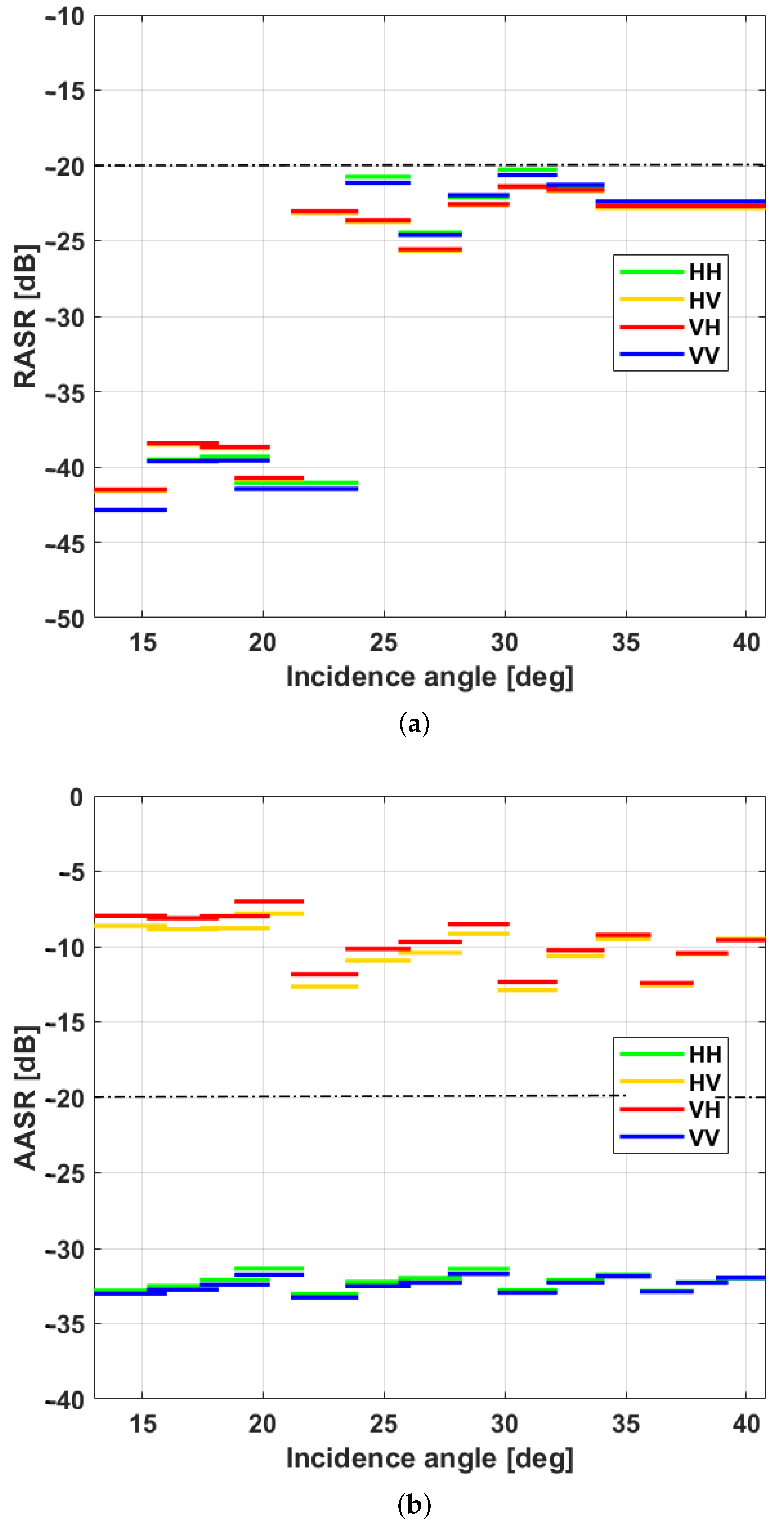
2.1. Ambiguity-to-Signal Ratio

The circular polarization pulses emitted by hybrid quad-pol SAR can be decomposed into two orthogonal linear polarized components, and they are described as
R = H jV L = H + jV ,
where L and R represent the left- and right-circular polarization pulses respectively, H and V are the horizontal and vertical polarized components separately, and j is the imaginary unit. At this point, the amplitudes of the H- and V-polarized components are equal.
The scattered echo signals can be received by the H- and V-polarized antennas at the same time. Afterwards, the full scattering matrix of each pixel on the ground is obtained, and the image processing is realized [17]. Besides, SAR images can be converted from the circular to linear polarized basis, which can be expressed as [17]
S HH S HV S VH S VV = S h h S h v S v h S v v + i o d d RAR i S h h i S h v i S v h i S v v i + i e v e n RAR i S h h i S h v i S v h i S v v i ,
where o d d and e v e n represent the odd and even ambiguity signals respectively, and RAR i donates the range ambiguity ratio.
It can be seen from (2) that the echo signals of hybrid quad-pol SAR in the linear polarized basis are disturbed by the echoes with the same polarization as them. Therefore, its range ambiguity-to-signal ratio (RASR) can be represented as [35,36,37]
RASR p q = n = 1 N σ p q 0 ( η n ) f = B p / 2 B p / 2 G 2 ( θ n , f ) Q 2 ( f ) d f R n 3 sin η n σ p q 0 ( η m a i n ) f = B p / 2 B p / 2 G 2 ( θ m a i n , f ) Q 2 ( f ) d f R m a i n 3 sin η m a i n ,
where θ m a i n and θ n are the aspect angles of the antenna irradiating targets and the n t h ambiguity region respectively, η m a i n and η n are the incidence angles of the antenna beam illuminating targets and the n t h ambiguity region separately, n represents the n t h ambiguity echo and n { 1 , 2 , , N } , N is the number of ambiguity regions, σ p q 0 ( η ) is the backscattering coefficient of the p q polarization, p , q { H , V } , Q ( f ) is the weighting of Doppler spectrum in data processing, G 2 ( θ , f ) is the two-way antenna pattern, f is the Doppler frequency, B p is the Doppler bandwidth, R m a i n and R n are the distances from the antenna phase center to targets and the center of the n t h ambiguity region respectively.
Moreover, the azimuth ambiguity-to-signal ratio (AASR) of echo signals with different polarizations can be described by Equation (4) [18,35]. In (4), G 2 ( f ) is the two-way antenna power pattern in azimuth, PRF represents the pulse repetition frequency (the azimuth sampling rate), and the other symbols have the same meanings as those in (3).
AASR HH = σ HV 0 σ HH 0 m = m o d d + f = B p / 2 B p / 2 G 2 ( f + m PRF ) Q 2 ( f ) d f + m = m e v e n m 0 + f = B p / 2 B p / 2 G 2 ( f + m PRF ) Q 2 ( f ) d f f = B p / 2 B p / 2 G 2 ( f ) Q 2 ( f ) d f AASR HV = σ HH 0 σ HV 0 m = m o d d + f = B p / 2 B p / 2 G 2 ( f + m PRF ) Q 2 ( f ) d f + m = m e v e n m 0 + f = B p / 2 B p / 2 G 2 ( f + m PRF ) Q 2 ( f ) d f f = B p / 2 B p / 2 G 2 ( f ) Q 2 ( f ) d f AASR VH = σ VV 0 σ VH 0 m = m o d d + f = B p / 2 B p / 2 G 2 ( f + m PRF ) Q 2 ( f ) d f + m = m e v e n m 0 + f = B p / 2 B p / 2 G 2 ( f + m PRF ) Q 2 ( f ) d f f = B p / 2 B p / 2 G 2 ( f ) Q 2 ( f ) d f AASR VV = σ VH 0 σ VV 0 m = m o d d + f = B p / 2 B p / 2 G 2 ( f + m PRF ) Q 2 ( f ) d f + m = m e v e n m 0 + f = B p / 2 B p / 2 G 2 ( f + m PRF ) Q 2 ( f ) d f f = B p / 2 B p / 2 G 2 ( f ) Q 2 ( f ) d f
When the L-band SAR illuminates the soil, rocks, grassland, shrubs, short vegetation, dry snow, etc., at an incidence angle of 50 degrees, the backscattering coefficient of cross-pol echo signals is 7–13 dB lower than that of co-pol echoes [38]. Therefore, the co-pol echo energy in the odd ambiguity region contributes greatly to the AASR of cross-pol echo signals in (4), which is an important factor limiting the swath width of hybrid quad-pol SAR [39,40].

2.2. Performance Analysis
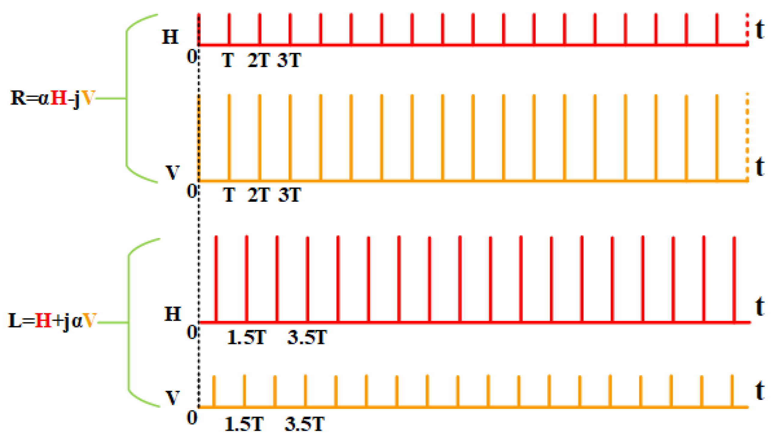
Hybrid quad-pol SAR improves the range ambiguity performance of conventional quad-pol SAR [17]. However, the azimuth ambiguity of its cross-pol echo signals is serious [18]. Therefore, it is difficult to meet the mission requirements of spaceborne SAR with wide swath. To intuitively highlight its shortcomings, the range and azimuth ambiguities of hybrid quad-pol SAR are presented below based on (3), (4) and system parameters in Table 1.
The results are shown in Figure 1. (a) is the RASR of hybrid quad-pol SAR, which is smaller than −20 dB within the preset observation range, meeting the design requirements of spaceborne SAR, and (b) is its AASR varying with incidence angle. It can be seen that the AASR of co-pol echo signals is smaller than −30 dB, but that of cross-pol echoes is larger than −13 dB, far higher than the required minimum value of −20 dB, reducing the system performance of hybrid quad-pol SAR.
It is clear that hybrid quad-pol SAR ameliorates the RASR of conventional quad-pol SAR, but introduces extremely severe cross-pol azimuth ambiguity. For the sake of reducing its azimuth ambiguity, PRF can be properly increased. According to the constraint of minimum SAR antenna area [39], the elevation of PRF inevitably leads to a reduction of swath width. In other words, it is difficult for hybrid quad-pol SAR to increase the swath width under the premise of meeting the ambiguity requirements of SAR. Therefore, a spaceborne full-pol SAR system that can suppress the cross-pol azimuth ambiguity of hybrid quad-pol SAR is put forward below, and its influence on improving the cross-pol azimuth ambiguity performance is described.

3. WAM Full-Pol SAR

It can be seen from (4) that the ambiguity of the cross-pol echo signals of hybrid quad-pol SAR is mainly affected by the co-pol ambiguity energy. Thus, the amplitude of emitted radar signals can be weighted to make the AASR of cross-pol echo signals meet the design requirements of spaceborne SAR. This section proposes a spaceborne WAM full-pol SAR system based on the time-domain weighting method and describes two imaging modes of a proposed SAR system in the following.

3.1. The First Imaging Mode

Spaceborne WAM full-pol SAR alternately transmits right- and left-ellipse polarization pulses with unequal H- and V-polarized components to weight the odd ambiguity energy of the cross-pol echoes of hybrid quad-pol SAR and reduce the azimuth ambiguity of its cross-pol echoes. The signals emitted by the first imaging mode of WAM full-pol SAR are expressed as
R = α H jV L = H + j α V ,
where α ( α = 0 represents the conventional quad-pol SAR, and α = 1 is the hybrid quad-pol SAR.) is the amplitude weighting factor, and 0 < α < 1 .
The transmission sequence diagram of the first imaging mode is shown in Figure 2. First, a right-ellipse polarization pulse is emitted, and the amplitude of its V vector is greater than that of H. After that, a left-ellipse polarization pulse is emitted whose amplitude of V vector is less than that of H. Afterwards, right- and left-ellipse polarization pulses are transmitted alternately. At the receiving end, H- and V-polarized antennas are used to concurrently receive the echoes for imaging processing. Then the derived full-pol SAR images can be converted to the linear polarized basis, which is described as
S HH S HV S VH S VV = S h h S h v S v h S v v + i o d d RAR i S h h i S h v i S v h i S v v i · 2 α 1 + α 2 j j α 2 1 + α 2 j α 2 j 1 + α 2 2 α 1 + α 2 + i e v e n RAR i S h h i S h v i S v h i S v v i .
It is obvious that the polarization characteristics of the even ambiguity energy of echo signals are the same as those of the ideal echoes. However, the characteristics of odd ambiguity energy are different. According to the definition of ambiguity-to-signal ratio, the RASR and AASR of the first imaging mode can be expressed by Equations (7) and (8), respectively.
RASR HH = n = 1 N o d d [ 2 α σ HH 0 ( η n ) ] 2 + [ ( 1 α 2 ) σ HV 0 ( η n ) ] 2 1 + α 2 f = B p / 2 B p / 2 G 2 ( θ n , f ) Q 2 ( f ) d f R n 3 sin η n + n = 1 N e v e n σ HH 0 ( η n ) f = B p / 2 B p / 2 G 2 ( θ n , f ) Q 2 ( f ) d f R n 3 sin η n σ HH 0 ( η m a i n ) f = B p / 2 B p / 2 G 2 ( θ m a i n , f ) Q 2 ( f ) d f R m a i n 3 sin η m a i n RASR HV = n = 1 N o d d [ 2 α σ HV 0 ( η n ) ] 2 + [ ( 1 α 2 ) σ HH 0 ( η n ) ] 2 1 + α 2 f = B p / 2 B p / 2 G 2 ( θ n , f ) Q 2 ( f ) d f R n 3 sin η n + n = 1 N e v e n σ HV 0 ( η n ) f = B p / 2 B p / 2 G 2 ( θ n , f ) Q 2 ( f ) d f R n 3 sin η n σ HV 0 ( η m a i n ) f = B p / 2 B p / 2 G 2 ( θ m a i n , f ) Q 2 ( f ) d f R m a i n 3 sin η m a i n RASR VH = n = 1 N o d d [ 2 α σ VH 0 ( η n ) ] 2 + [ ( 1 α 2 ) σ VV 0 ( η n ) ] 2 1 + α 2 f = B p / 2 B p / 2 G 2 ( θ n , f ) Q 2 ( f ) d f R n 3 sin η n + n = 1 N e v e n σ VH 0 ( η n ) f = B p / 2 B p / 2 G 2 ( θ n , f ) Q 2 ( f ) d f R n 3 sin η n σ VH 0 ( η m a i n ) f = B p / 2 B p / 2 G 2 ( θ m a i n , f ) Q 2 ( f ) d f R m a i n 3 sin η m a i n RASR VV = n = 1 N o d d [ 2 α σ VV 0 ( η n ) ] 2 + [ ( 1 α 2 ) σ VH 0 ( η n ) ] 2 1 + α 2 f = B p / 2 B p / 2 G 2 ( θ n , f ) Q 2 ( f ) d f R n 3 sin η n + n = 1 N e v e n σ VV 0 ( η n ) f = B p / 2 B p / 2 G 2 ( θ n , f ) Q 2 ( f ) d f R n 3 sin η n σ VV 0 ( η m a i n ) f = B p / 2 B p / 2 G 2 ( θ m a i n , f ) Q 2 ( f ) d f R m a i n 3 sin η m a i n
AASR HH = ( 2 α 1 + α 2 · σ HV 0 σ HH 0 ) 2 + ( α 2 1 1 + α 2 ) 2 m = m o d d + f = B p / 2 B p / 2 G 2 ( f + m PRF ) Q 2 ( f ) d f + m = m e v e n m 0 + f = B p / 2 B p / 2 G 2 ( f + m PRF ) Q 2 ( f ) d f f = B p / 2 B p / 2 G 2 ( f ) Q 2 ( f ) d f AASR HV = ( 2 α 1 + α 2 · σ HH 0 σ HV 0 ) 2 + ( α 2 1 1 + α 2 ) 2 m = m o d d + f = B p / 2 B p / 2 G 2 ( f + m PRF ) Q 2 ( f ) d f + m = m e v e n m 0 + f = B p / 2 B p / 2 G 2 ( f + m PRF ) Q 2 ( f ) d f f = B p / 2 B p / 2 G 2 ( f ) Q 2 ( f ) d f AASR VH = ( 2 α 1 + α 2 · σ VV 0 σ VH 0 ) 2 + ( α 2 1 1 + α 2 ) 2 m = m o d d + f = B p / 2 B p / 2 G 2 ( f + m PRF ) Q 2 ( f ) d f + m = m e v e n m 0 + f = B p / 2 B p / 2 G 2 ( f + m PRF ) Q 2 ( f ) d f f = B p / 2 B p / 2 G 2 ( f ) Q 2 ( f ) d f AASR VV = ( 2 α 1 + α 2 · σ VH 0 σ VV 0 ) 2 + ( α 2 1 1 + α 2 ) 2 m = m o d d + f = B p / 2 B p / 2 G 2 ( f + m PRF ) Q 2 ( f ) d f + m = m e v e n m 0 + f = B p / 2 B p / 2 G 2 ( f + m PRF ) Q 2 ( f ) d f f = B p / 2 B p / 2 G 2 ( f ) Q 2 ( f ) d f
In (7), the RASR of cross-pol echo signals is mainly affected by the odd co-pol ambiguity energy. Compared with the conventional quad-pol SAR, the boost of its range ambiguity performance is related to the weighting factor α .
In (8), σ HH 0 and σ VV 0 have the greatest influence on the AASR of cross-pol echo signals. Their weighting coefficient is 2 α / ( 1 + α 2 ) and varies with α . As such, the effects of co-pol ambiguity energy on the AASR of cross-pol echoes can be reduced by selecting an optimal α in the system design of spaceborne SAR.
Based on (7), (8), and system parameters in Table 1, the range and azimuth ambiguities of the first imaging mode are estimated by simulations, and the results are shown in Figure 3, where α [ 0 , 1 ] .
It can be seen from Figure 3 that the AASR of echo signals is lower than −20 dB when α < 0.05 , which meets the design requirements of spaceborne SAR. However, the RASR of cross-pol echo signals cannot meet that. Therefore, DBF or antenna pattern synthesis [28] needs to be adopted to reduce the influence of RASR on the SAR system.

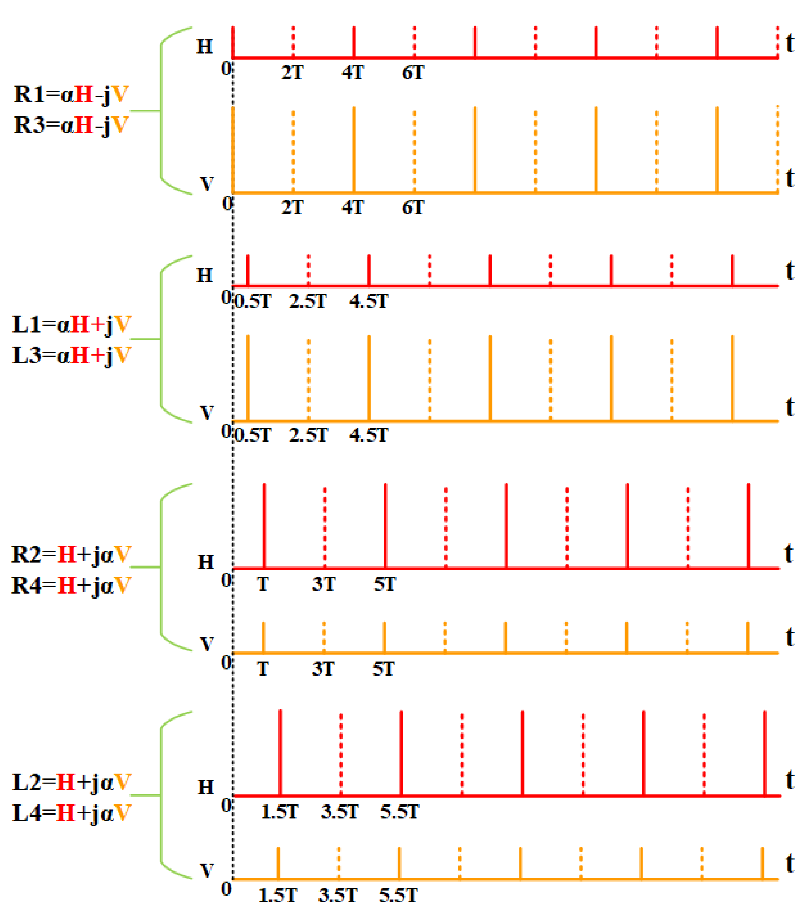
3.2. The Second Imaging Mode
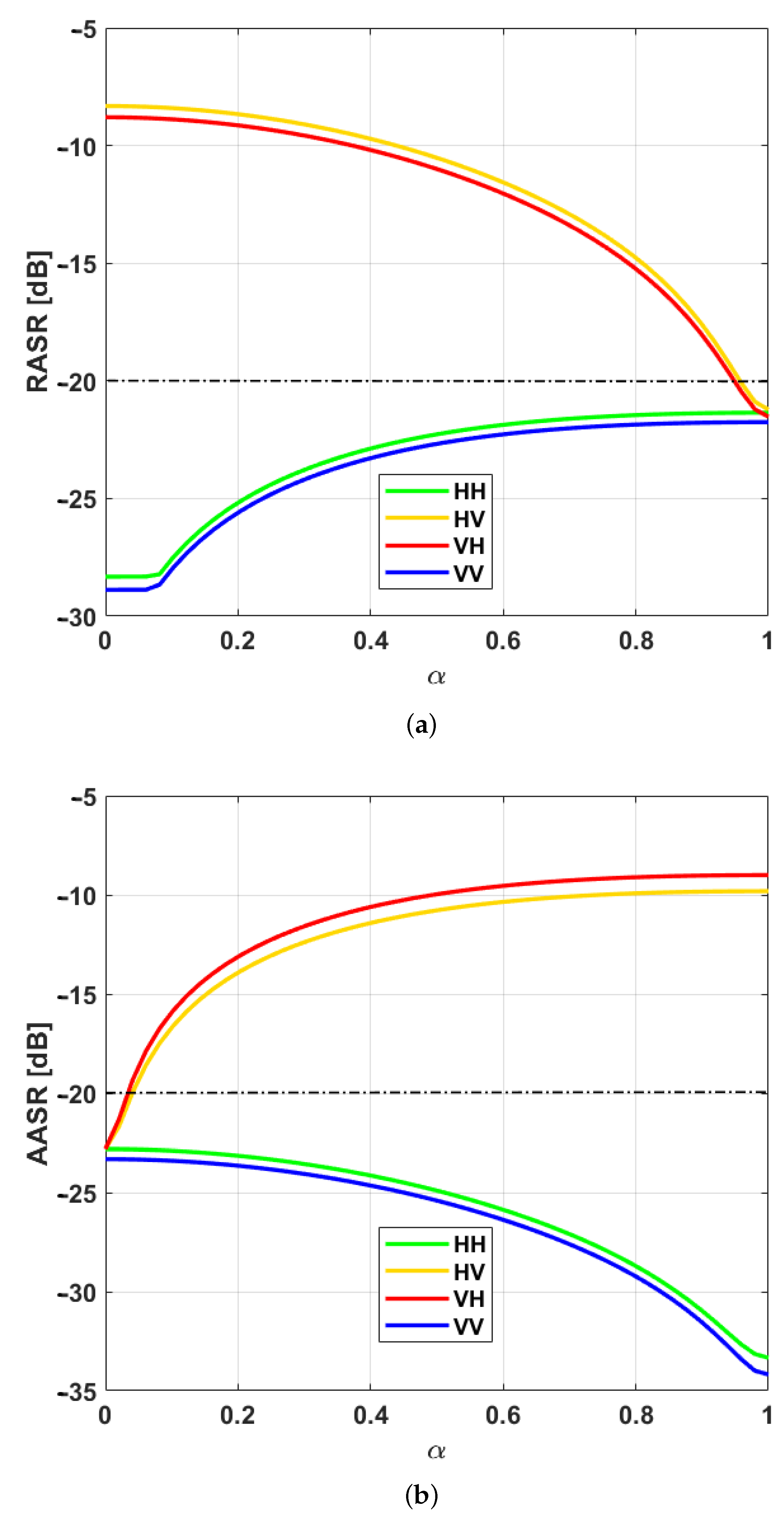
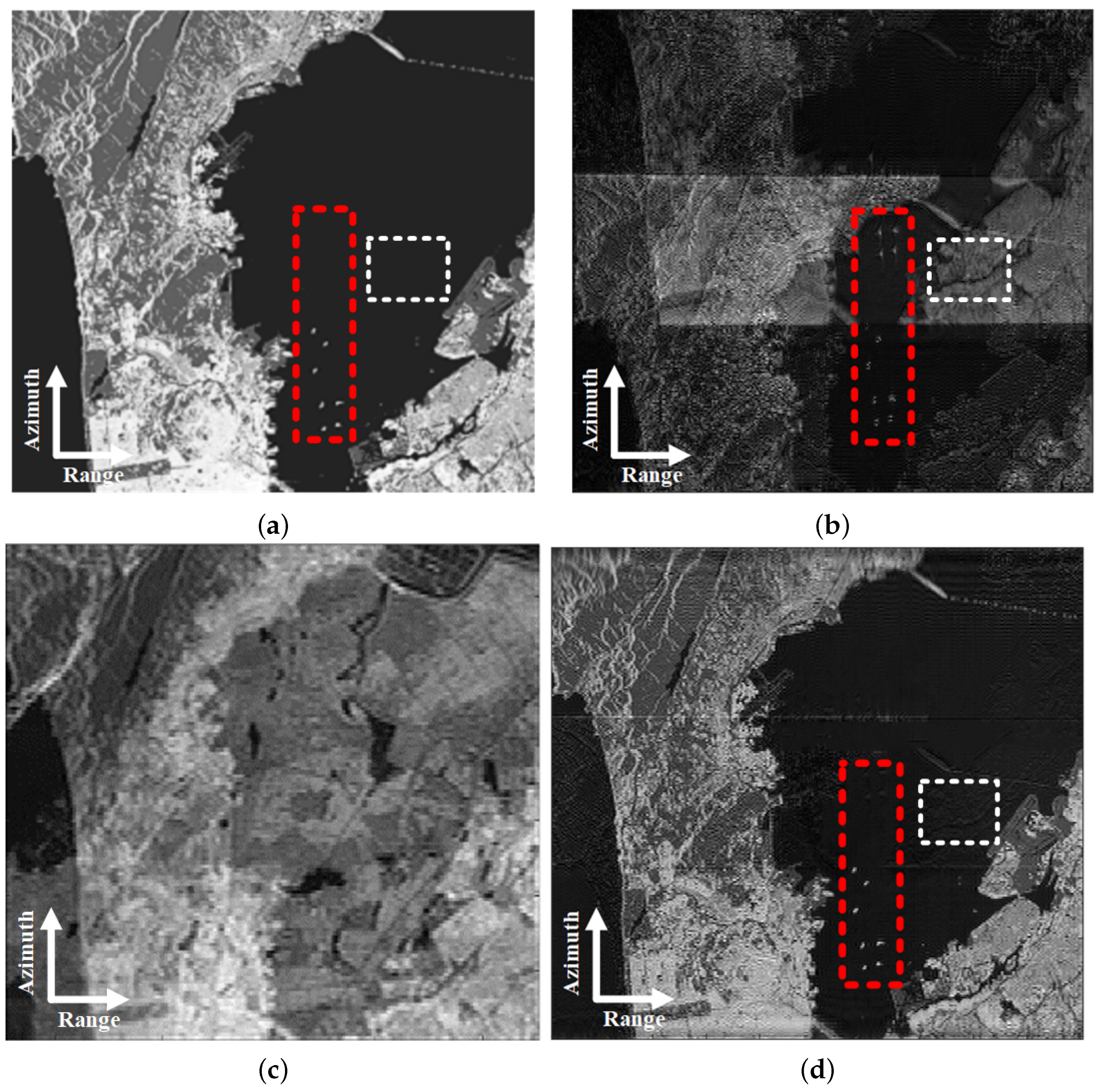
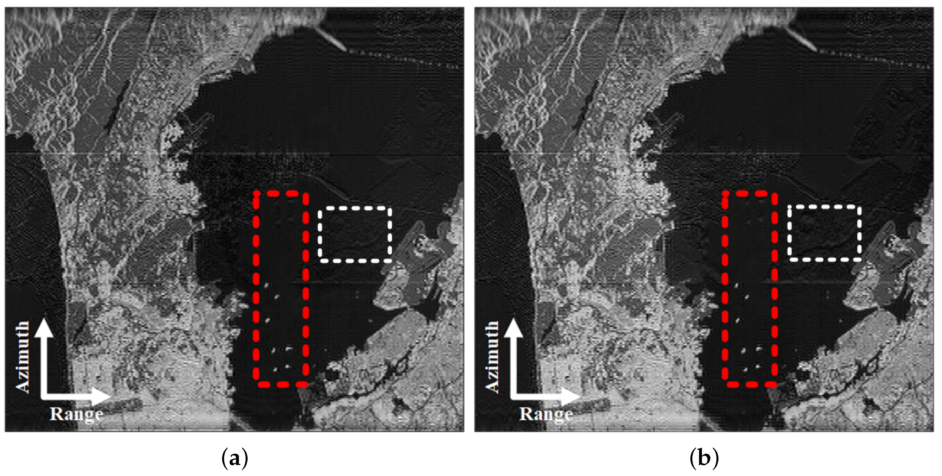
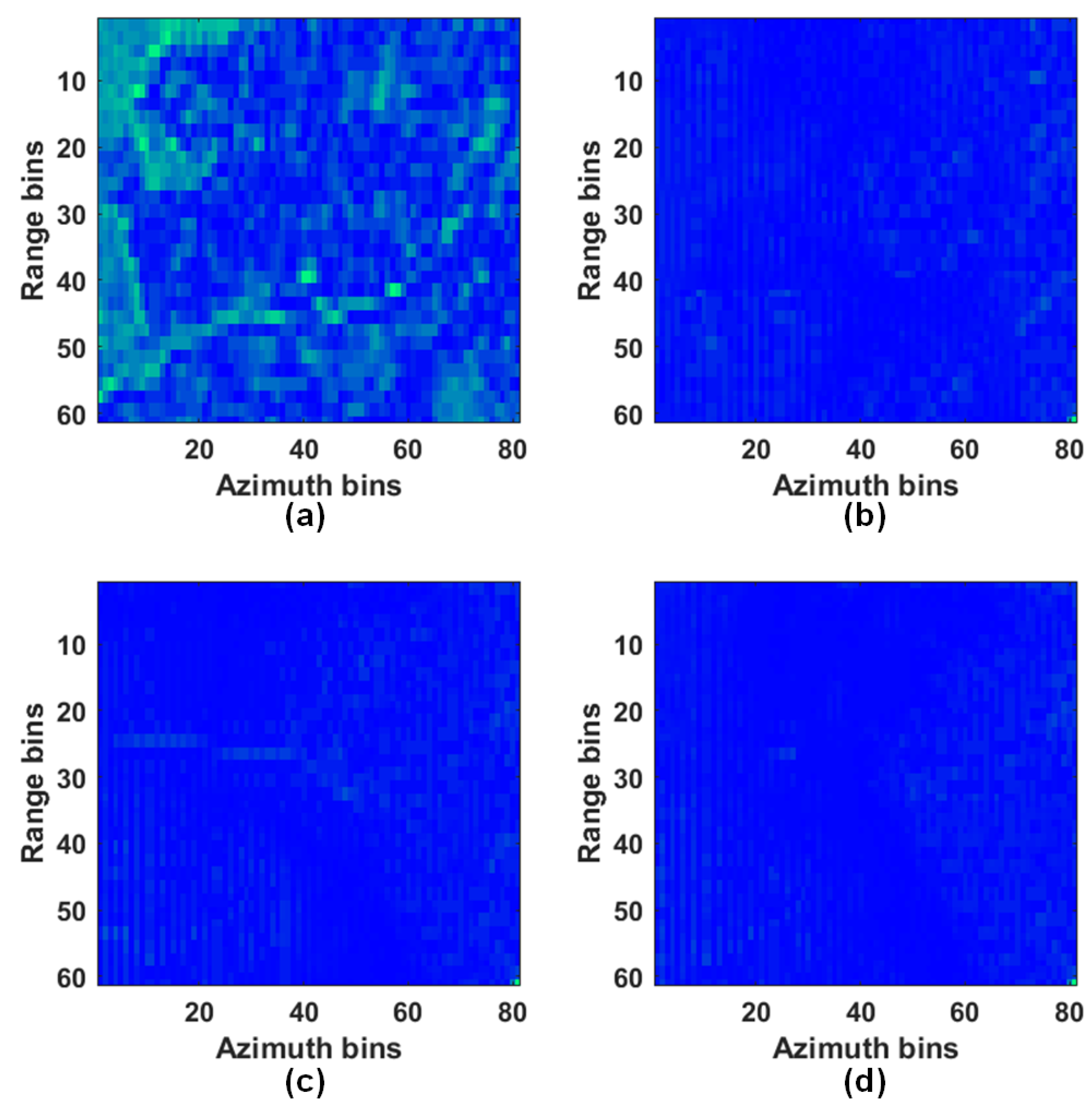
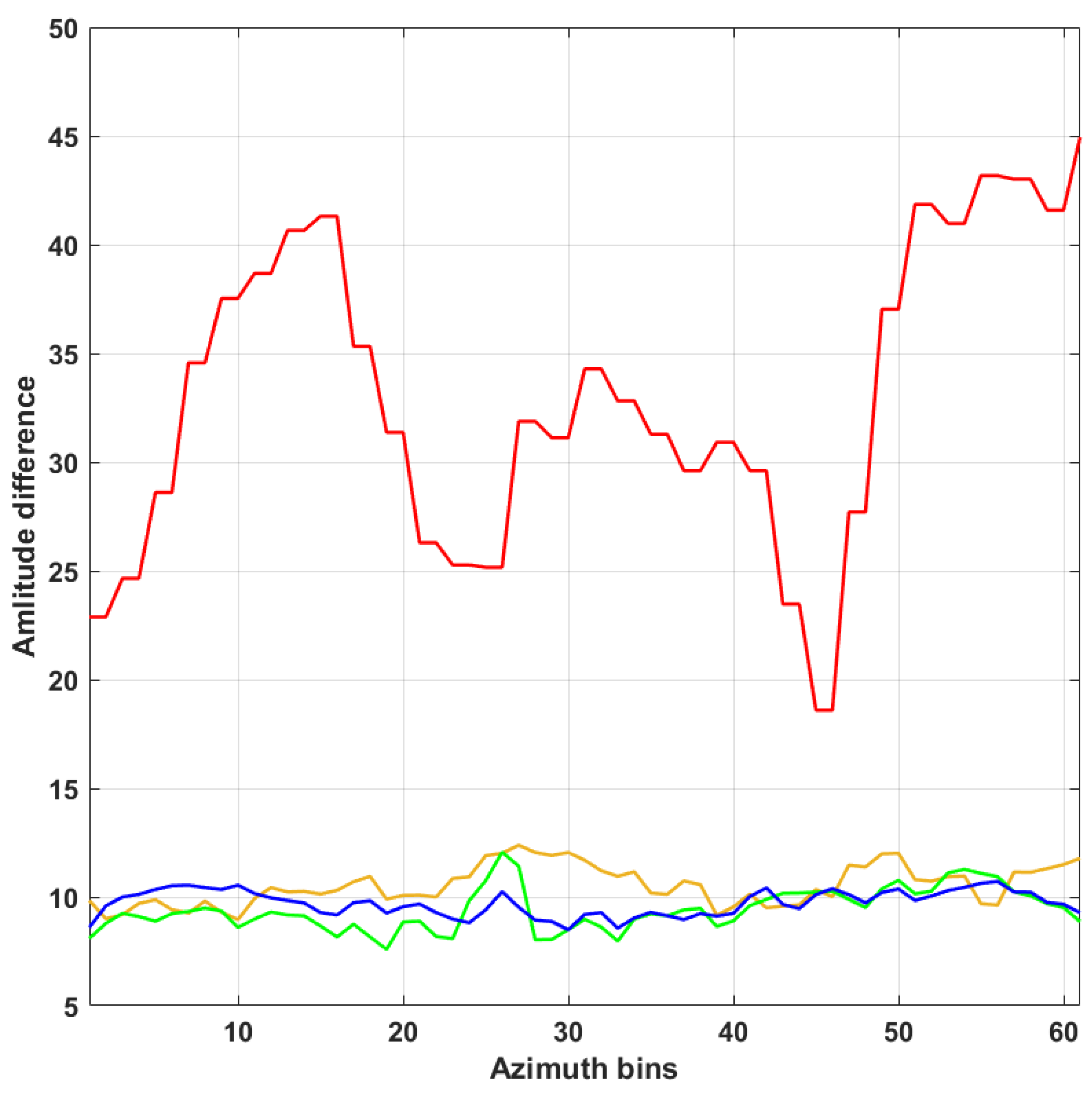
Different from the first imaging mode, the radar signals emitted by the second imaging mode of WAM full-pol SAR are described as
R 1 = α H jV L 1 = α H + jV R 2 = H j α V L 2 = H + j α V R 3 = α H jV L 3 = α H + jV R 4 = H j α V L 4 = H + j α V ,
where α is the weighting factor, and 0 < α < 1 . Besides, the sequence of radar signals emitted in this mode is R 1 , L 1 , R 2 , L 2 , R 3 , L 3 , R 4 , L 4 , R 1 , L 1 , R 2 , L 2 , ⋯. Its signal transmission sequence is shown in Figure 4. The solid lines represent R 1 , L 1 , R 2 and L 2 respectively, and the dotted lines donate R 3 , L 3 , R 4 and L 4 separately.
In the case of adopting the sequence of signal transmission described in (9), the received echo signals can be expressed as
S HR 1 S HR 2 S HR 3 S HR 4 S HL 1 S HL 2 S HL 3 S HL 4 S VR 1 S VR 2 S VR 3 S VR 4 S VL 1 S VL 2 S VL 3 S VL 4 = α S HH S HH j α S HV jS HV 0 jS HV 0 α S HH S HH + j α S HV α S VH S VH j α S VV jS VV 0 jS VV 0 α S VH S VH + j α S VV + j S HV 0 α S HH S HH j α S HV α S HH S HH + j α S HV jS HV 0 jS VV 0 α S VH S VH j α S VV α S VH S VH + j α S VV jS VV 0 = S HH S HV 0 0 0 0 S HH S HV S VH S VV 0 0 0 0 S VH S VV · α 1 0 0 0 j α j 0 0 0 α 1 j 0 0 j α + S HH S HV 0 0 0 0 S HH S HV S VH S VV 0 0 0 0 S VH S VV · 0 0 α 1 j 0 0 j α α 1 0 0 0 j α j 0 ,
where S HR i , S HL i , S VR i and S VL i represent R i and L i signals received by the H- and V-polarized antennas respectively, and i { 1 , 2 , 3 , 4 } .
For the SAR system operating in L-band, it can be assumed that the echo signals satisfy S HH = S VV = μ S HV = μ S VH , and μ represents the ratio of co-pol echo signal to cross-pol echo signal. At this point, the echo signals in the linear polarized basis can be derived by multiplying the weighting matrices of Equations (11) and (12) on the right side of (10), which can be represented by Equations (13) and (14) respectively. γ i and μ i represent the intermediate variables, and they can be calculated according to (10)–(12).
It can be seen from (13) and (14) that the echoes of the second imaging mode can be almost extracted without pollution in the linear polarized basis. Its AASR can be derived based on the above mentioned method of converting the signals from the ellipse to a linear polarized basis, and it can be described by Equation (15), when the weighting factor α is small. It can be obtained from (15) that the second imaging mode improves the azimuth ambiguity of hybrid quad-pol SAR. Moreover, the derivation of the AASR of the second imaging mode is detailed below.
A = α 3 j α 2 α j 1 j α 3 α 2 j α α j α 3 j α 2 α 2 j α 1 j α 3 · 1 α 4 1
B = α j α 3 j α 2 α 2 j α 1 j α 3 α 3 j α 2 α j 1 j α 3 α 2 j α · 1 α 4 1
S HR 1 S HR 2 S HR 3 S HR 4 S HL 1 S HL 2 S HL 3 S HL 4 S VR 1 S VR 2 S VR 3 S VR 4 S VL 1 S VL 2 S VL 3 S VL 4 · A = S HH S HV 0 0 0 0 S HH S HV S VH S VV 0 0 0 0 S VH S VV + 0 0 γ 1 γ 2 γ 3 γ 4 0 0 0 0 γ 5 γ 6 γ 7 γ 8 0 0
S HR 1 S HR 2 S HR 3 S HR 4 S HL 1 S HL 2 S HL 3 S HL 4 S VR 1 S VR 2 S VR 3 S VR 4 S VL 1 S VL 2 S VL 3 S VL 4 · B = 0 0 μ 1 μ 2 μ 3 μ 4 0 0 0 0 μ 5 μ 6 μ 7 μ 8 0 0 + S HH S HV 0 0 0 0 S HH S HV S VH S VV 0 0 0 0 S VH S VV
The radar echo signals, S HR i and S HL i , received by the H-polarized antenna can be described by Equation (16). In (16), i [ 1 , 2 , 3 , 4 ] , T is the interval between the transmitted signals, and δ ( t ) is the Dirac function.
AASR m = m 0 + f = B p / 2 B p / 2 G 2 ( f + m PRF ) Q 2 ( f ) d f f = B p / 2 B p / 2 G 2 ( f ) Q 2 ( f ) d f
According to (16), the time domain expression of S HH in (13) can be obtained, and it is expressed by Equation (17). Similarly, the expressions of S HV , S VH and S VV echoes can also be derived, and they are described by Equation (18).
Furthermore, the expressions of (17) and (18) in the frequency domain can be derived and described by Equation (19), when α is small. It is clear that the ambiguities of echo signals with different polarizations have the same polarization characteristic as themselves. Similarly, the frequency domain expression of the signal in (14) can also be derived, and it has a similar form with (19). These also validate the AASR of the echo signals in (15) and indicate that the AASR of the second imaging mode can satisfy the design requirements of spaceborne SAR.
The echo signals received by the second imaging mode with range ambiguity can be expressed by Equation (20). It is obvious that it is difficult to describe its RASR with an analytic expression. Therefore, it is a better approach to estimate its range ambiguity performance by scene simulations. A simple theoretical analysis of the second mode reveals that its range ambiguity is serious, and it also needs to be suppressed by DBF or antenna pattern synthesis operation [28].
S HR 1 ( t ) = α S HH ( t ) n δ ( t 4 n T ) j S HV ( t ) n δ ( t 4 n T ) S HR 2 ( t ) = S HH ( t ) n δ ( t 4 n T T ) j α S HV ( t ) n δ ( t 4 n T T ) S HR 3 ( t ) = α S HH ( t ) n δ ( t 4 n T 2 T ) j S HV ( t ) n δ ( t 4 n T 2 T ) S HR 4 ( t ) = S HH ( t ) n δ ( t 4 n T 3 T ) j α S HV ( t ) n δ ( t 4 n T 3 T ) S HL 1 ( t ) = α S HH ( t ) n δ ( t 4 n T 0.5 T ) + j S HV ( t ) n δ ( t 4 n T 0.5 T ) S HL 2 ( t ) = S HH ( t ) n δ ( t 4 n T 1.5 T ) + j α S HV ( t ) n δ ( t 4 n T 1.5 T ) S HL 3 ( t ) = α S HH ( t ) n δ ( t 4 n T 2.5 T ) + j S HV ( t ) n δ ( t 4 n T 2.5 T ) S HL 4 ( t ) = S HH ( t ) n δ ( t 4 n T 3.5 T ) + j α S HV ( t ) n δ ( t 4 n T 3.5 T )
S HH ( t ) = S HR 1 ( t ) α 3 α 4 1 + S HR 2 ( t ) 1 α 4 1 + S HR 3 ( t ) α α 4 1 + S HR 4 ( t ) α 2 α 4 1 S HH ( t ) = S HL 1 ( t ) α α 4 1 + S HL 2 ( t ) α 2 α 4 1 + S HL 3 ( t ) α 3 α 4 1 + S HL 4 ( t ) 1 α 4 1
S HV ( t ) = S HR 1 ( t ) j α 2 α 4 1 + S HR 2 ( t ) j α 3 α 4 1 + S HR 3 ( t ) j α 4 1 + S HR 4 ( t ) j α α 4 1 S HV ( t ) = S HL 1 ( t ) j α 4 1 + S HL 2 ( t ) j α α 4 1 + S HL 3 ( t ) j α 2 α 4 1 + S HL 4 ( t ) j α 3 α 4 1 S VH ( t ) = S VR 1 ( t ) α 3 α 4 1 + S VR 2 ( t ) 1 α 4 1 + S VR 3 ( t ) α α 4 1 + S VR 4 ( t ) α 2 α 4 1 S VH ( t ) = S VL 1 ( t ) α α 4 1 + S VL 2 ( t ) α 2 α 4 1 + S VL 3 ( t ) α 3 α 4 1 + S VL 4 ( t ) 1 α 4 1 S VV ( t ) = S VR 1 ( t ) j α 2 α 4 1 + S VR 2 ( t ) j α 3 α 4 1 + S VR 3 ( t ) j α 4 1 + S VR 4 ( t ) j α α 4 1 S VV ( t ) = S VL 1 ( t ) j α 4 1 + S VL 2 ( t ) j α α 4 1 + S VL 3 ( t ) j α 2 α 4 1 + S VL 4 ( t ) j α 3 α 4 1
S HH ( f ) = S HR 1 ( f ) · α 3 α 4 1 + S HR 2 ( f ) · 1 α 4 1 + S HR 3 ( f ) · α α 4 1 + S HR 4 ( f ) · α 2 α 4 1 n S HH ( f n 4 T ) · e j π 2 n S HH ( f ) = S HL 1 ( f ) · α α 4 1 + S HL 2 ( f ) · α 2 α 4 1 + S HL 3 ( f ) · α 3 α 4 1 + S HL 4 ( f ) · 1 α 4 1 n S HH ( f n 4 T ) · e j 3 π 2 n S HV ( f ) = S HR 1 ( f ) · j α 2 α 4 1 + S HR 2 ( f ) · j α 3 α 4 1 + S HR 3 ( f ) · j α 4 1 + S HR 4 ( f ) · j α α 4 1 n S HV ( f n 4 T ) · e j π n S HV ( f ) = S HL 1 ( f ) · j α 4 1 + S HL 2 ( f ) · j α α 4 1 + S HL 3 ( f ) · j α 2 α 4 1 + S HL 4 ( f ) · j α 3 α 4 1 n S HV ( f n 4 T ) S VH ( f ) = S VR 1 ( f ) · α 3 α 4 1 + S VR 2 ( f ) · 1 α 4 1 + S VR 3 ( f ) · α α 4 1 + S VR 4 ( f ) · α 2 α 4 1 n S VH ( f n 4 T ) · e j π 2 n S VH ( f ) = S VL 1 ( f ) · α α 4 1 + S VL 2 ( f ) · α 2 α 4 1 + S VL 3 ( f ) · α 3 α 4 1 + S VL 4 ( f ) · 1 α 4 1 n S VH ( f n 4 T ) · e j 3 π 2 n S VV ( f ) = S VR 1 ( f ) · j α 2 α 4 1 + S VR 2 ( f ) · j α 3 α 4 1 + S VR 3 ( f ) · j α 4 1 + S VR 4 ( f ) · j α α 4 1 n S VV ( f n 4 T ) · e j π n S VV ( f ) = S VL 1 ( f ) · j α 4 1 + S VL 2 ( f ) · j α α 4 1 + S VL 3 ( f ) · j α 2 α 4 1 + S VL 4 ( f ) · j α 3 α 4 1 n S VV ( f n 4 T )
S HR 1 S HR 2 S HR 3 S HR 4 S HL 1 S HL 2 S HL 3 S HL 4 S VR 1 S VR 2 S VR 3 S VR 4 S VL 1 S VL 2 S VL 3 S VL 4 = i = 1 + 8 k k N S HL 1 S HL 2 S HL 3 S HL 4 S HR 2 S HR 3 S HR 4 S HR 1 S VL 1 S VL 2 S VL 3 S VL 4 S VR 2 S VR 3 S VR 4 S VR 1 i + i = 2 + 8 k k N S HR 2 S HR 3 S HR 4 S HR 1 S HL 2 S HL 3 S HL 4 S HL 1 S VR 2 S VR 3 S VR 4 S VR 1 S VL 2 S VL 3 S VL 4 S VL 1 i + i = 3 + 8 k k N S HL 2 S HL 3 S HL 4 S HL 1 S HR 3 S HR 4 S HR 1 S HR 2 S VL 2 S VL 3 S VL 4 S VL 1 S VR 3 S VR 4 S VR 1 S VR 2 i + i = 4 + 8 k k N S HR 3 S HR 4 S HR 1 S HR 2 S HL 3 S HL 4 S HL 1 S HL 2 S VR 3 S VR 4 S VR 1 S VR 2 S VL 3 S VL 4 S VL 1 S VL 2 i + i = 5 + 8 k k N S HL 3 S HL 4 S HL 1 S HL 2 S HR 4 S HR 1 S HR 2 S HR 3 S VL 3 S VL 4 S VL 1 S VL 2 S VR 4 S VR 1 S VR 2 S VR 3 i + i = 6 + 8 k k N S HR 4 S HR 1 S HR 2 S HR 3 S HL 4 S HL 1 S HL 2 S HL 3 S VR 4 S VR 1 S VR 2 S VR 3 S VL 4 S VL 1 S VL 2 S VL 3 i + i = 7 + 8 k k N S HL 4 S HL 1 S HL 2 S HL 3 S HR 1 S HR 2 S HR 3 S HR 4 S VL 4 S VL 1 S VL 2 S VL 3 S VR 1 S VR 2 S VR 3 S VR 4 i + i = 8 + 8 k k N k 0 S HR 1 S HR 2 S HR 3 S HR 4 S HL 1 S HL 2 S HL 3 S HL 4 S VR 1 S VR 2 S VR 3 S VR 4 S VL 1 S VL 2 S VL 3 S VL 4 i
Based on (15) and system parameters in Table 1, a simulation is executed for the second imaging mode, and its azimuth ambiguity is shown in Figure 5. It can be seen that the AASR is smaller than −21 dB when α = 0.02 , which meets the design requirements of spaceborne SAR.
Only when α is small can the AASR of cross-pol echo signals in the two imaging modes meet the design requirements of spaceborne SAR. However, the SAR antennas work in the full saturated transmission state, and it is very difficult to modulate the amplitude of transmitted signals without changing the antenna pattern. Thus, in order to realize the two imaging modes of WAM full-pol SAR system, it is necessary to design an advanced antenna that can flexibly adjust its transmission amplitude.
In order to further verify the two imaging mode of WAM full-pol SAR, some scene simulations are carried out below based on the system parameters in Table 1.

4. Simulations

The following scene simulations are mainly used to verify that the two imaging modes of a WAM full-pol SAR system can suppress the azimuth ambiguity of cross-pol echo signals. In the simulations, the WAM full-pol SAR adopts DBF to suppress range ambiguities, and the echoes received by its multiple channels are weighted by the linearly constrained minimum variance (LCMV) beamformer [41].
Based on the system parameters in Table 1, some scene simulations are conducted for the two imaging modes. The results of the first imaging mode are shown in Figure 6. It should be noted that only Figure 6a was measured by SAR satellite [12], which serves as the input to simulations, and the simulations were manipulated by the computer that was configured with i7-7700 CPU, eight cores, eight threads, and 32-GB RAM.
Some special areas in Figure 6 are highlighted by the red dotted boxes to evaluate the azimuth ambiguity suppression capability of the proposed SAR system. As shown in Figure 6b, the azimuth ambiguity of the HV image derived by hybrid quad-pol SAR is serious compared with the input image of (a), and it is hard to determine the number of vessels at sea, as shown in the area selected by the red box. Besides, it is difficult for the first imaging mode to remove the range ambiguity in the absence of DBF or antenna pattern synthesis operation [28], resulting in the submergence of vessels by strong ambiguity targets on the urban area, as shown in (c). However, the vessels can be clearly seen in the image obtained by the first imaging mode with DBF, as shown in the selected area of (d), and this indicates that the first imaging mode has the capability of azimuth ambiguity suppression. It should be mentioned that Figure 6c is the result of superposition of one SAR image from the target area and another urban image from the ambiguity area, as described in [28], and (d) is the result of suppressing the ambiguity area energy using the sixteen-channel DBF filter.
The polarimetric SAR images obtained by the second imaging mode with DBF are shown in Figure 7. It can be seen that the azimuth ambiguity of cross-pol images obtained by this mode is the same as that of the first imaging mode, and the number of vessels in the red box can be seen clearly.
To further quantify the azimuth ambiguity performance of a proposed SAR system, some special areas in Figure 6 and Figure 7 are highlighted by the white dotted boxes, and they are enlarged, as shown in Figure 8.
The sum of the four images in Figure 8 along the range direction is respectively subtracted from the sum of the area selected by the white box in Figure 6a along the range direction, and their amplitude differences along the azimuth direction are obtained, as shown in Figure 9. It can be derived from Figure 9 that the amplitude difference between the original image and the images obtained by the two imaging modes of the proposed SAR system is smaller than that of hybrid quad-pol SAR. That is to say, the proposed SAR system can suppress the azimuth ambiguity of cross-pol echo signals well.
In short, the simulation results imply that the proposed WAM full-pol SAR system has better azimuth ambiguity performance and has the potential to be applied to spaceborne full-pol SAR in the future. In addition, the results also verify the theoretical analysis above.

5. Conclusions

In summary, a spaceborne WAM full-pol SAR system is put forward, and it can effectively suppress the cross-pol azimuth ambiguity of a hybrid quad-pol SAR. The boost of the azimuth ambiguity performance of the hybrid quad-pol SAR by the two imaging modes of the proposed SAR system is detailed. Furthermore, the L-band system parameters are used to evaluate their range and azimuth ambiguities. In addition, CSA is adopted to execute scene simulations on them, and the results imply that the WAM full-pol SAR system can effectively suppress the azimuth ambiguity of the hybrid quad-pol SAR and verify the theoretical analysis.

Author Contributions

Conceptualization, Y.Z. (Yanyan Zhang) and R.W.; methodology, Y.Z. (Yanyan Zhang), P.L. and Y.Z. (Yongwei Zhang); software, Y.Z. (Yanyan Zhang); validation, Y.Z. (Yanyan Zhang); writing—original draft preparation, Y.Z. (Yanyan Zhang) and S.C.; writing—review and editing, Y.Z. (Yanyan Zhang), R.W., P.L. and Y.Z. (Yongwei Zhang); visualization, Y.Z. (Yanyan Zhang) and S.C.; project administration, R.W. and Y.D.; funding acquisition, R.W. and Y.D. All authors have read and agreed to the published version of the manuscript.

Funding

This work was supported in part by the National Science Fund for Distinguished Young Scholars under Grant 61825106 and by the National Science Fund under Grant 61701479.

Data Availability Statement

Not applicable.

Conflicts of Interest

The authors declare no conflict of interest.

References

  1. Raney, R.K. Hybrid-Polarity SAR Architecture. IEEE Trans. Geosci. Remote Sens. 2007, 45, 3397–3404. [Google Scholar] [CrossRef] [Green Version]
  2. Raney, R.K. Hybrid-quad-pol SAR. In Proceedings of the IGARSS 2008 IEEE International Geoscience and Remote Sensing Symposium, Boston, MA, USA, 8–11 July 2008; Volume 4, pp. 491–493. [Google Scholar]
  3. Blunt, S.D.; Mokole, E.L. Overview of radar waveform diversity. IEEE Aerosp. Electron. Syst. Mag. 2016, 31, 2–42. [Google Scholar] [CrossRef]
  4. Sadjadi, F. Improved target classification using optimum polarimetric SAR signatures. IEEE Trans. Aerosp. Electron. Syst. 2002, 38, 38–49. [Google Scholar] [CrossRef]
  5. Aldhubaib, F.; Shuley, N.V. Radar Target Recognition Based on Modified Characteristic Polarization States. IEEE Trans. Aerosp. Electron. Syst. 2010, 46, 1921–1933. [Google Scholar] [CrossRef]
  6. Touzi, R.; Hurley, J.; Vachon, P.W. Optimization of the Degree of Polarization for Enhanced Ship Detection Using Polarimetric RADARSAT-2. IEEE Trans. Geosci. Remote Sens. 2015, 53, 5403–5424. [Google Scholar] [CrossRef]
  7. McCormick, P.; Jakabosky, J.; Blunt, S.D.; Allen, C.; Himed, B. Joint polarization/waveform design and adaptive receive processing. In Proceedings of the 2015 IEEE Radar Conference, Arlington, VA, USA, 10–15 May 2015; pp. 1382–1387. [Google Scholar]
  8. Fritz, J.P.; Chandrasekar, V. A Fully Polarimetric Characterization of the Impact of Precipitation on Short Wavelength Synthetic Aperture Radar. IEEE Trans. Geosci. Remote Sens. 2012, 50, 2037–2048. [Google Scholar] [CrossRef]
  9. Lim, S.; Chandrasekar, V.; Bringi, V.N. Hydrometeor classification system using dual-polarization radar measurements: Mode improvements and in situ verification. IEEE Trans. Geosci. Remote Sens. 2005, 43, 792–801. [Google Scholar] [CrossRef]
  10. Bringi, V.N.; Chandrasekar, V. Polarimetric Doppler Weather Radar: Principles and Applications; Cambridge University Press: Cambridge, UK, 2001. [Google Scholar]
  11. Li, P.; Zhao, F.; Liu, D.; Ou, N.; Cao, C.; Liu, X.; Zhang, Y.; Deng, Y.; Wang, R. First Demonstration of Hybrid Quad-Pol SAR Based on P-Band Airborne Experiment. IEEE Trans. Geosci. Remote Sens. 2021. [Google Scholar] [CrossRef]
  12. Zhang, R.; Wang, Y.; Hu, J.; Yang, W.; Chen, J.; Zhu, X.X. SAR4LCZ-Net: A Complex-valued Convolutional Neural Network for Local Climate Zones Classification Using Gaofen-3 Quad-pol SAR Data. IEEE Trans. Geosci. Remote Sens. 2021. [Google Scholar] [CrossRef]
  13. Campbell, B.A. Scale-dependent surface roughness behavior and its impact on empirical models for radar backscatter. IEEE Trans. Geosci. Remote Sens. 2009, 47, 3480–3488. [Google Scholar] [CrossRef]
  14. Truong-Loi, M.-L.; Saatchi, S.; Jaruwatanadilok, S. Soil moisture estimation under tropical forests using UHF radar polarimetry. IEEE Trans. Geosci. Remote Sens. 2015, 53, 1718–1727. [Google Scholar] [CrossRef]
  15. Yang, Z.; Xu, H.; Huang, P.; Liu, A.; Tian, M.; Liao, G. Preliminary Results of Multichannel SAR-GMTI Experiments for Airborne Quad-Pol Radar System. IEEE Trans. Geosci. Remote Sens. 2020, 58, 3822–3840. [Google Scholar] [CrossRef]
  16. Hoang, H.K.; Bernier, M.; Duchesne, S.; Tran, Y.M. Rice Mapping Using RADARSAT-2 Dual- and Quad-Pol Data in a Complex Land-Use Watershed: Cau River Basin (Vietnam). IEEE J. Sel. Top. Appl. Earth Observ. Remote Sens. 2016, 9, 3082–3096. [Google Scholar] [CrossRef] [Green Version]
  17. Raney, R.K.; Freeman, A.; Jordan, R.L. Improved Range Ambiguity Performance in Quad-Pol SAR. IEEE Trans. Geosci. Remote Sens. 2012, 50, 349–356. [Google Scholar] [CrossRef]
  18. Villano, M.; Krieger, G.; Moreira, A. New Insights Into Ambiguities in Quad-Pol SAR. IEEE Trans. Geosci. Remote Sens. 2017, 55, 3287–3308. [Google Scholar] [CrossRef]
  19. Li, J.; Ji, Y.; Zhang, Y.; Zhang, Q.; Dong, Z. Effects of Ionosphere Polarimetric Dispersion on Lower-Frequency Spaceborne SAR. In Proceedings of the 2018 IEEE 3rd International Conference on Signal and Image Processing (ICSIP), Shenzhen, China, 13–15 July 2018; pp. 510–515. [Google Scholar]
  20. Villano, M.; Krieger, G. Impact of Azimuth Ambiguities on Interferometric Performance. IEEE Geosci. Remote Sens. Lett. 2012, 9, 896–900. [Google Scholar] [CrossRef] [Green Version]
  21. Di Martino, G.; Iodice, A.; Riccio, D.; Ruello, G. Filtering of Azimuth Ambiguity in Stripmap Synthetic Aperture Radar Images. IEEE J. Sel. Top. Appl. Earth Obs. Remote Sens. 2014, 7, 3967–3978. [Google Scholar] [CrossRef] [Green Version]
  22. Cloude, S.R. A General Elliptical Formulation of Hybrid-POLSAR System Ambiguities. IEEE Geosci. Remote Sens. Lett. 2019, 16, 1066–1069. [Google Scholar] [CrossRef]
  23. Krieger, G.; Gebert, N.; Moreira, A. Multidimensional waveform encoding for spaceborne synthetic aperture radar systems. In Proceedings of the 2007 International Waveform Diversity and Design Conference, Pisa, Italy, 4–8 June 2007; pp. 282–286. [Google Scholar]
  24. Krieger, G.; Gebert, N.; Moreira, A. Multidimensional Waveform Encoding: A New Digital Beamforming Technique for Synthetic Aperture Radar Remote Sensing. IEEE Trans. Geosci. Remote Sens. 2008, 46, 31–46. [Google Scholar] [CrossRef] [Green Version]
  25. Krieger, G.; Gebert, N.; Moreira, A. Multidimensional radar waveforms a new paradigm for the design and operation of highly performant spaceborne synthetic aperture radar systems. In Proceedings of the 2007 IEEE International Geoscience and Remote Sensing Symposium, Barcelona, Spain, 23–28 July 2007; pp. 4937–4941. [Google Scholar]
  26. Krieger, G.; Gebert, N.; Moreira, A. Multidimensional waveform encoding for synthetic aperture radar remote sensing. In Proceedings of the 2007 IET International Conference on Radar Systems, Edinburgh, UK, 15–18 October 2007; pp. 1–5. [Google Scholar]
  27. Krieger, G.; Gebert, N.; Younis, M.; Moreira, A. Advanced synthetic aperture radar based on digital beamforming and waveform diversity. In Proceedings of the 2008 IEEE Radar Conference, Rome, Italy, 26–30 May 2008; pp. 1–6. [Google Scholar]
  28. Yang, C.; Ou, N.; Deng, Y.; Liu, D.; Zhang, Y.; Wang, N.; Wang, R. Pattern Synthesis Algorithm for Range Ambiguity Suppression in the LT-1 Mission via Sequential Convex Optimizations. IEEE Trans. Geosci. Remote Sens. 2021. [Google Scholar] [CrossRef]
  29. Zhang, L.; Li, H.; Qiao, Z.; Xu, Z. A Fast BP Algorithm With Wavenumber Spectrum Fusion for High-Resolution Spotlight SAR Imaging. IEEE Geosci. Remote Sens. Lett. 2014, 11, 1460–1464. [Google Scholar] [CrossRef]
  30. Raney, R.K.; Runge, H.; Bamler, R.; Cumming, I.G.; Wong, F.H. Precision SAR processing using chirp scaling. IEEE Trans. Geosci. Remote Sens. 1994, 32, 786–799. [Google Scholar] [CrossRef]
  31. Duan, S.; Li, J. High Squint SAR Processing Using Modified Extended Chirp Scaling. In Proceedings of the First International Conference on Innovative Computing, Information and Control (ICICIC’06), Beijing, China, 30 August–1 September 2006; Volume 1, pp. 358–361. [Google Scholar]
  32. Moreira, A.; Mittermayer, J.; Scheiber, R. Extended chirp scaling algorithm for air- and spaceborne SAR data processing in stripmap and ScanSAR imaging modes. IEEE Trans. Geosci. Remote Sens. 1996, 34, 1123–1136. [Google Scholar] [CrossRef]
  33. Hui, K.; Jie, C.; Wei, Y. A modified chirp-scaling algorithm for spaceborne squinted sliding spotlight SAR data processing. In Proceedings of the 2015 IEEE 5th Asia-Pacific Conference on Synthetic Aperture Radar (APSAR), Singapore, 1–4 September 2015; pp. 459–461. [Google Scholar]
  34. Dudczyk, J.; Kawalec, A. Optimizing the minimum cost flow algorithm for the phase unwrapping process in sar radar. Bulletin of the Polish Academy of Sciences. Tech. Sci. 2014, 62, 511–516. [Google Scholar]
  35. Jin, G.; Aubry, A.; De Maio, A.; Wang, R.; Wang, W. Quasi-Orthogonal Waveforms for Ambiguity Suppression in Spaceborne Quad-Pol SAR. IEEE Trans. Geosci. Remote Sens. 2021, 60, 5204617. [Google Scholar] [CrossRef]
  36. Zhang, Y.; Wang, W.; Deng, Y.; Zhang, Z.; Wang, R. Ambiguity Suppression of Cross-Pol Signals by DPCA With DBF Reflector for Hybrid/±π/4 Quad-Pol SAR. IEEE Trans. Geosci. Remote Sens. 2021, 60, 5202613. [Google Scholar] [CrossRef]
  37. Zhao, P.; Deng, Y.; Wang, W.; Zhang, Y.; Wang, R. Ambiguity Suppression Based on Joint Optimization for Multichannel Hybrid and ±π/4 Quad-Pol SAR Systems. Remote Sens. 2021, 13, 1907. [Google Scholar] [CrossRef]
  38. Ulaby, F.T.; Dobson, M.C. Handbook of Radar Scattering Statistics for Terrain; Artech House: Norwood, MA, USA, 1989. [Google Scholar]
  39. Freeman, A.; Johnson, W.T.K.; Hunecutt, B.; Jordan, R.; Hensley, S.; Siqueira, P.; Curlander, J. The “Myth” of the minimum SAR antenna area constraint. IEEE Trans. Geosci. Remote Sens. 2000, 38, 320–324. [Google Scholar] [CrossRef] [Green Version]
  40. Zhang, Y.; Zhang, Y.; Deng, Y.; Chang, S.; Liu, D.; Wang, R. A Quad-Pol SAR Imaging Mode with Sound Azimuth Ambiguity. In Proceedings of the 2020 IEEE Radar Conference (RadarConf20), Florence, Italy, 21–25 September 2020; pp. 1–5. [Google Scholar] [CrossRef]
  41. Van Trees, H.L. Optimum Array Processing; John Wiley & Sons: Hoboken, NJ, USA, 2004; ISBN 978-0471463832. [Google Scholar]
Figure 1. Ambiguity performance of hybrid quad-pol SAR. (a,b) represent the RASR and AASR respectively.
Remotesensing 14 00155 g001
Figure 2. Transmission sequence diagram of the first imaging mode.
Remotesensing 14 00155 g002
Figure 3. Ambiguity performance of the first mode. (a) The maximum value of RASR varies with α . (b) The maximum value of AASR varies with α .
Remotesensing 14 00155 g003
Figure 4. Transmission sequence diagram of the second imaging mode. The solid lines represent R 1 , L 1 , R 2 and L 2 respectively, and the dotted lines donate R 3 , L 3 , R 4 and L 4 separately.
Remotesensing 14 00155 g004
Figure 5. Azimuth ambiguity performance of the second mode with α = 0.02 .
Remotesensing 14 00155 g005
Figure 6. Simulation results of the first mode. (a) is the input HV image. (b) is the HV image of hybrid quad-pol SAR. (c) is the HV image of the first imaging mode without DBF. (d) is the HV image of the first imaging mode with DBF. The white dots in the red box represent vessels.
Remotesensing 14 00155 g006
Figure 7. Simulation results of the second mode. (a,b) represent the HV and VH images respectively. The white dots in the red box represent vessels.
Remotesensing 14 00155 g007
Figure 8. Some special areas selected by the white dotted boxes of Figure 6 and Figure 7. (ad) correspond to Figure 6b,d and Figure 7a,b, respectively.
Remotesensing 14 00155 g008
Figure 9. Amplitude differences between the images in Figure 8 and that in Figure 6a along the azimuth direction. The red, orange, green and blue curves represent the amplitude differences of (a), (b), (c) and (d) in Figure 6a and Figure 8, respectively.
Remotesensing 14 00155 g009
Table 1. Main system parameters for simulations of full-pol SAR.
ParametersValue
Satellite height607 Km
Carrier frequency1.26 GHz
Signal bandwidth80 MHz
Pulse width20 us
Antenna length9.8 m
Antenna height3.4 m
Peak power15,840 W
Antenna efficiency75%
Resolution/Width6 m/30 km
Look angle12∼33 deg
Squint angle0 deg
Duty cycle16%
Weighting factor α 0.02
Backscattering coefficient[38]
Publisher’s Note: MDPI stays neutral with regard to jurisdictional claims in published maps and institutional affiliations.

