Article

Direction Estimation of Aerial Image Object Based on Neural Network

State Key Laboratory of Information Engineering in Surveying, Mapping, and Remote Sensing, Wuhan University, Wuhan 430079, China
*
Author to whom correspondence should be addressed.
Remote Sens. 2022, 14(15), 3523; https://doi.org/10.3390/rs14153523
Submission received: 21 May 2022 / Revised: 19 July 2022 / Accepted: 20 July 2022 / Published: 22 July 2022

Abstract

:
Due to the inherent periodicity of the angle, the direction of the object detected by the current rotating object detection algorithm is fuzzy. In order to solve this problem, this paper proposes a rotating object direction estimation method based on a neural network, which determines the unique direction of the object by predicting the direction vector of the object. Firstly, we use the two components (sin θ , cos θ ) of the direction vector and the length and width parameters of the object to express the object model. Secondly, we construct a neural network model to predict the parameters used to express the object model. However, there is a constraint that the sum of the squares of the two components of the direction vector of the object is equal to 1. Because each output element of the neural network is independent, it is difficult to learn the constrained data between such neurons. Therefore, the function transformation model is designed, and the network transformation layer is added. Finally, affine transformation is used to transform the object parameters and carry out regression calculation, so as to detect the object and determine the direction of the object at the same time. This paper uses three sets of data to carry out the experiment, which are DOTA 1.5, HRSC, and UCAS-AOD data sets. It can be seen from the experimental results that for the object with correct ground truth, the proposed method can not only locate the object but also estimate the direction of the object accurately.

Graphical Abstract

1. Introduction

In recent years, neural networks have developed rapidly, particularly Convolutional Neural Networks (CNN), which have been widely used in computer vision, speech recognition, medical research, intelligent games, and many other fields [1], and are still being updated and iterated. In the field of computer vision, image object detection is one of the hot issues. The mainstream CNN algorithm focuses on object recognition and positioning. Through the optimization of network structure and detection algorithms, it has made breakthroughs in the improvement of detection speed and accuracy [2]. The estimation of object direction has been developing with the problem of object detection. Obtaining the direction information of an object, on the one hand, it can make for a deeper semantic understanding of the image and produce more applications. For example, the direction information of the object is used to correct the image, predict the occurrence probability of events associated with the specific direction of the object, or predict the intention of the object by estimating the direction information of the dynamic object. On the other hand, the mainstream CNN algorithms use the traditional axis-aligned bounding box to mark the position of the object on the image. However, when the objects in the image are very close to each other and tilted, the horizontal rectangle cannot well represent the geometric position of the object. For objects inclined at any angle, especially inclined slender strip objects such as ships, vehicles, and pencils, if the direction of the object can be predicted, it is more suitable to use the inclined bounding box with direction information for positioning. In this way, the object can be included more accurately, the proportion of background information in the box can be reduced, and the information utilization of the bounding box can be increased. At the same time, in the area with dense objects, the overlap rate between multiple bounding boxes can be greatly reduced and different object individuals can be distinguished more effectively. The comparison between the traditional bounding box and the inclined bounding box is shown in Figure 1.
Therefore, we should study the estimation of the direction of an object while realizing object detection so that the detected object has more abundant geometric position information. At present, there are many studies on object direction estimation [3]. One is to predict the four corner coordinates of the quadrilateral and train eight position coordinate parameters through the network. Thus, the quadrilateral boundary box with arbitrary shape and the corresponding predicted direction angle are realized. This kind of method does not use constraints to maintain the shape of quadrilateral, so that the predicted quadrilateral boundary box may be deformed [4]. Another kind of detection method is to bring the direction angle describing the direction into the training data of the network for regression and output the angle as the predicted value. However, there is a sudden change in the direction angle value after one full rotation; that is, from 360° to 0°. In fact, 360° and 0° refer to the same direction. Therefore, if the angle value is used for regression, the predicted values of the network at 0° and 360° are likely to have great errors in value [3,5].
In order to solve the above problems, this paper proposes an object representation method based on a direction vector, which uses two direction components (sin θ, cos θ) of the object direction θ to express the direction of the object. Because sinθ and cosθ have monotonicity and continuity in [0°, 360°), the above mutation problem will not occur. While predicting the direction components, the coordinates of the center point and the length and width of the object are predicted to realize the constraint on the geometry of the object. In addition, when predicting the two direction components (sin θ, cos θ), there is a constraint with the sum of squares of 1, while the output range of the traditional neural network is (−∞, +∞). Therefore, in order to ensure that the predicted value of the neural network meets the constraints, this paper introduces the network conversion layer [6,7]. That is, the transformation function is constructed to make the predicted value of the neural network naturally meet the constraints and improve the adaptability of the network model. At the same time, the traditional IoU calculation method is the ratio of union and intersection of two regions. This method only considers the positioning accuracy of the object. For the periodic problem of angle, this method is difficult to evaluate the accuracy of direction estimation. Therefore, this paper proposes a new accuracy index to quantitatively verify the accuracy of angle estimation.
To sum up, the main contributions of this paper are as follows:
(1)
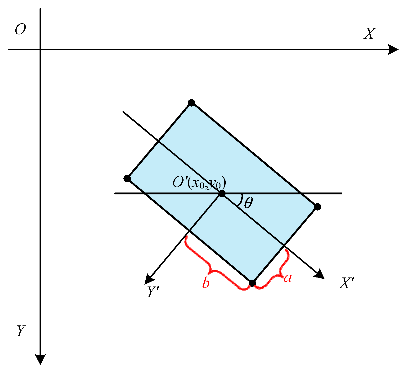
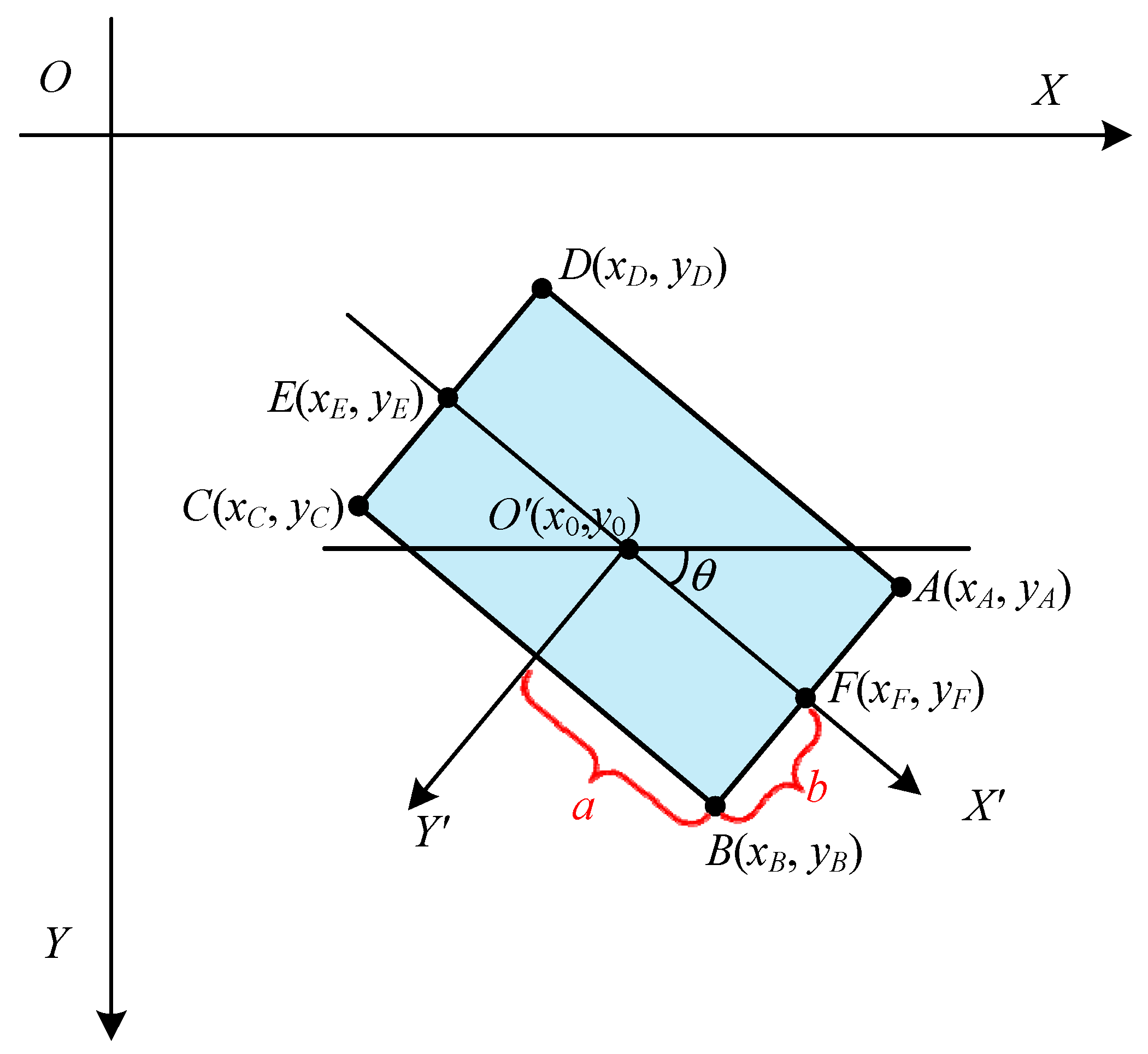
This paper presents a new object expression method, which uses two components of the direction angle to represent the direction of the object. Then, the geometric model of the object is constrained by combining the coordinates of the center point and the length and width of the object.
(2)
The change function is adopted, and the network conversion layer is introduced. Then, the output components of the neural network naturally meet the constraints and improve the adaptability of the network model.
(3)
This paper can realize object detection and direction estimation at the same time. Then, an accuracy index for quantitatively evaluating the accuracy of angle estimation is proposed.

2. Related Work

With the rapid development of deep learning technology, object detection methods based on deep learning have become the mainstream method of object detection. It mainly uses CNN to extract image features and realize end-to-end training. Commonly used CNN mainly include LeNet-5 [8], AlexNet [9], VGgNetwork [10], GoogleNet [11], and ResNet [12]. The object detection network uses these convolution networks to extract the image features to complete the object detection in the image. Neural network methods for object detection can usually be divided into two-stage object detection methods and one-stage object detection methods. The two-stage object detection methods mainly include R-CNN [13], Fast-RCNN [14], Faster-RCNN [15], FPN network [16], and Mask R-CNN [17]. The detection methods of one-stage mainly include YOLO [18] and SSD [19]. The one-stage detection method can directly realize the object detection task; the detection speed is fast, but the detection accuracy is slightly lower than that of the two-stage network.
The above mainstream CNN algorithms focus on object recognition and location, and most of them use axis-aligned bounding boxes to locate objects. In order to make a deeper semantic understanding of the image and locate various inclined objects more accurately, it is necessary to obtain the direction information of the objects. Therefore, in recent years, the research on image rotation features and object direction estimation has increased. Aiming at the limited ability of Deep Convolution Neural Network (DCNN) in dealing with image rotation, [20] proposed A Rotation Filter (ARF). In the convolution process, the directional features of the image are learned by rotation, and the feature response map with position and direction coding is generated. The DCNN of ARFs can be used to generate the deep features with invariable rotation in the class. Reference [21] proposes to add a rotation-invariant layer to the CNN to establish a rotation-invariant CNN model. The rotation invariant layer is realized by adding regularization constraints, so the established network can also recognize the rotation of the object. For the recognition of text objects in any direction, reference [22] proposed a Rotational Region CNN(R2CNN) to realize it. The method is as follows: first, Region Proposal Network (RPN) is used to predict the axis-aligned bounding box of text roughly. Then, through the features extracted from Region of Interest (ROI) pooling layers of different scales, refine the axis-aligned bounding box to obtain the minimum inclined bounding box. Finally, the final detection result is obtained by Non-Maximum Suppression (NMS).
For the recognition of remote sensing image objects in any direction, literature [23] focuses on the vehicle. Directional SSD is used to detect vehicles in any direction. In this method, the direction angle is directly incorporated into the attribute data of the object bounding box for regression, using preset rectangular boxes with different scales to generate detection bounding boxes in each feature map, and then calculate the offset value. Literature [24] studies ship objects, setting a nearly closed ship rotating enclosure space, predicting the possible area of ships, reducing the current search range, and generating several groups of candidates. Then, the best one is selected through the two-layer cascade linear model. Literature [17] can identify a variety of objects. By preset several groups of rotation boxes with specific angles, the prediction is carried out at each position based on the preset rotation boxes and the proportional characteristics of different types of objects. This method also adds a direction angle to the bounding box to describe the direction directly. These three methods all use the bounding box with angle information; that is, the inclined bounding box to locate and mark the object. At present, few scholars consider the periodicity of the angle of the object when estimating the object, so they lose the significance of direction estimation.

3. Algorithm Description

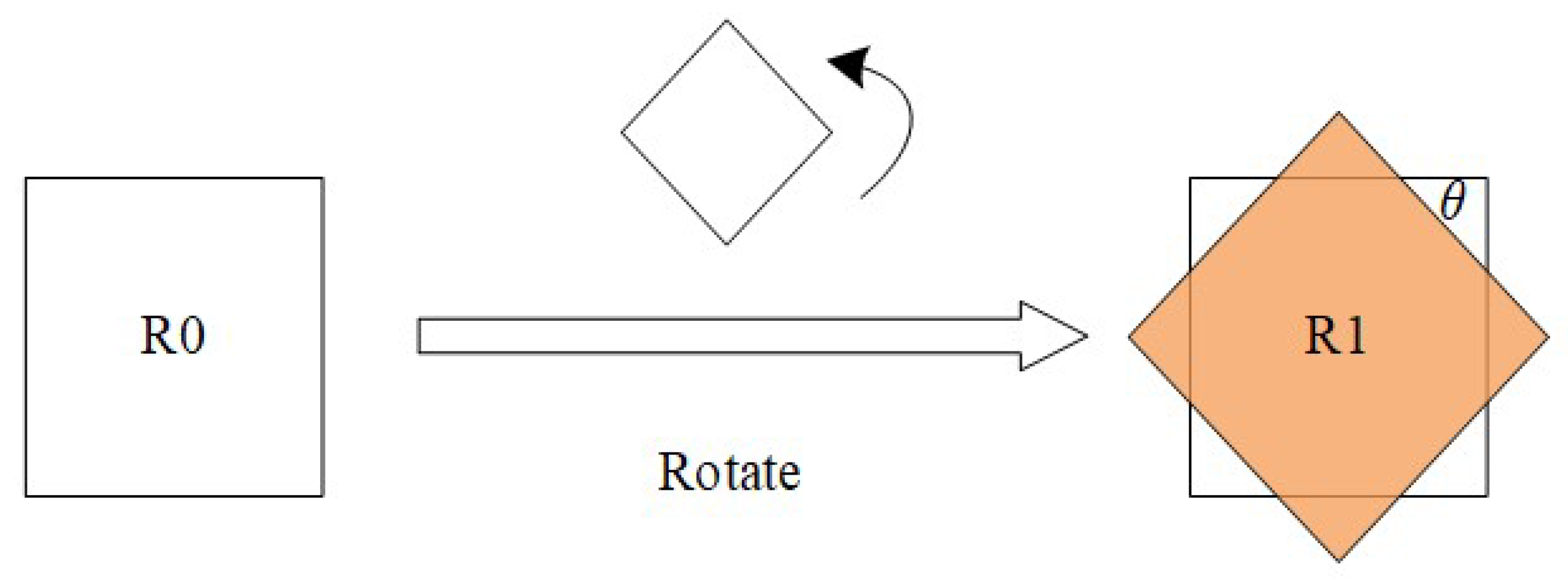
3.1. Representation of the Direction of the Object

For some objects without direction, such as the swimming pool, we do not consider their direction in the experiment. For some directional objects, we believe the direction of the object refers to the positive direction of the main axis of the object. For example, the direction of the aircraft is the direction from the tail to the nose on the central axis of the aircraft, and the direction of the ship is the direction from the stern to the bow on the central axis of the ship. In this paper, the direction angle of the object is defined as the included angle between the direction of the object and the X-axis in the image coordinate system, with a range of [0°, 360). However, since there is a sudden change in the value of the angle from 0° to 360° after one full cycle of rotation, in fact, 0° and 360° refer to the same direction. Therefore, if the value of the angle is used for regression, the predicted values of the network at 0° and 360° are likely to have great errors in value. If the two components cos θ and sin θ of the direction vector of the object have monotonicity and continuity, the above problems will not occur, so the direction of an object can be determined uniquely. Therefore, this paper intends to use the two components cos θ and sin θ of the direction vector of the object as the prediction data of the neural network. At the same time, the coordinates (x0, y0) of the center point, the length 2a, and the width 2b of the object are predicted. Six parameters (x0, y0, a, b, cos θ, sin θ) are used to represent the object. For ease of description, cos θ and sin θ are recorded as q0 and q1, respectively, and then the object parameters are expressed as (x0, y0, a, b, q0, q1).
As shown in Figure 2, XOY is the image coordinate system. The rectangular frame in the figure is the object to be detected, with a length of 2a and a width of 2b, (x0, y0) is the coordinate of the object’s center point under the image coordinate system X′O′Y′. X′O′Y′ is the object body coordinate system. The X′ axis is the main axis of the object, and the positive direction of X′ axis is the direction of the object. The included angle between the X′ axis and X axis is θ.

3.2. Network Structure

In this paper, the YOLO-v4 algorithm is improved. The overall structure of the improved network is shown in Figure 3. In order to preserve the object recognition function of the original YOLO-v4 network image, the branch of the corresponding scale is added after the backbone network to estimate the direction of objects. Therefore, in the improved network structure, a group of branches is responsible for predicting the central point coordinates, categories, and confidence of the object. Another group of branches is responsible for predicting the geometric length, width, and direction components of objects. The output results of the two groups of branches are combined one by one to obtain the final prediction result.
The features between the two groups of branches are not shared, and the branches will not interfere with each other. This can make the neural network learn the position features and rotation features of the object, respectively, and separate prediction can improve the prediction accuracy of the network.
Because the convolution kernel components between different output channels of the convolution network are completely independent, and the output components of different channels are also independent, the value range of neural network output is (−∞, ∞). Therefore, it is difficult for neural networks to predict the data with constraints between output components. For example, the sum of squares of the two components cos θ and sin θ is equal to 1. In order to solve this problem, this paper introduces the network conversion layer when constructing the neural network forward propagation model. That is, the components are constrained by the transformation function of the network conversion layer. Assuming that the variables predicted by the neural networks are (Q0, Q1), and the value range of Q0, Q1 is (−∞, ∞), after the transformation function, we get (q0, q1) and meet the constraint condition q02 + q12 = 1. Then, the forward propagation formula of the transformation function can be expressed as,
q 0 = Q 0 Q 0 2 + Q 1 2 q 1 = Q 1 Q 0 2 + Q 1 2
If q ¯ 0 and q ¯ 1 are the ground truth of the direction components, the loss function Eq is defined as,
E q = q 0 q ¯ 0 2 + q 1 q ¯ 1 2
As shown in Figure 4, the output values of the two channels of the neuron direction output layer in the object areas Q0 and Q1 are converted into unit direction components {q0, q1}.
In addition, assume that the ground truth of half the length and width of the object are a ¯ and b ¯ , respectively. Then, the calculation formula of the loss function of the length and width of the object is,
E a b = a a ¯ 2 + ( b b ¯ ) 2
Then, the calculation of the total loss function can be expressed as,
l o s s = l o s s yolov 4 + l o s s n e w = l o s s yolov 4 + W × H 1 i o b j E q + E a b
where lossyolov4 is the loss function of the original yolov4 model, W and H represent the scale of the feature map, respectively, 1iobj indicating whether there is an object in cell i.
In this paper, (q0, q1) is proposed to represent the direction of two-dimensional objects, which can be extended to the three-dimensional pose detection of objects.
The two components (q0, q1) of the object direction vector can be expanded into a quaternion vector (q0, q1, q2, q3) to represent the attitude of the object.

4. Experiment and Discussion

4.1. Calculate the Ground Truth
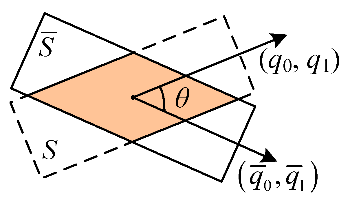
During training, in the training process, the known quantity is the coordinates of the four corners of the object. The ground truth of other parameters is calculated by the coordinates of four corners. As shown in Figure 5, the image coordinate system is XOY, and the object body coordinate system is X′O′Y′. We know that the coordinates of the four corners of the object in the image coordinate system are A(xA, yA), B(xB, yB), C(xC, yC), D(xD, yD). Then, the coordinates of the center point O′ of the object in the image coordinate system are,
x 0 = x A + x B + x C + x D 4 y 0 = y A + y B + y C + y D 4
The direction of the object is represented by a vector E F , expressed as,
d x = x A + x B 2 x C + x D 2 d y = y A + y B 2 y C + y D 2
The two components are obtained by uniting the vector, expressed as,
cos θ = d x d x 2 + d y 2 sin θ = d y d x 2 + d y 2
According to the affine transformation formula, the coordinates of the four corners of the object in the image coordinate system are transformed into the coordinates of the object body coordinate system,
x i y i = cos θ sin θ sin θ cos θ x i x y i y ( i = A , B , C , D )
Then, the length and width of the object are calculated according to the coordinates in the object body coordinate system; that is,
x i , y i = a , b    i = A a , b    i = B a , b    i = C a , b    i = D
We summarize the process of object detection in this paper, as shown in Figure 6. First, given a set of known data (X,Y), input the known image X into the network structure (as shown in Figure 3) to obtain the prediction result. Secondly, according to Figure 5 and Equations (5)–(9), the given Y is calculated as the ground truth of each parameter. Finally, the loss is calculated according to the predicted value and the ground truth.

4.2. Accuracy Index

In order to quantitatively verify the effectiveness of the experimental results, the following accuracy index is used to evaluate the object detection and recognition.
(1)
IoU
As shown in Figure 7, if S represents the prediction object area, S ¯ represents the ground truth of the object, and then the IoU calculation method is,
IoU = S S ¯ S S ¯
(2)
dot
Traditional methods only use IoU to evaluate the detection results without considering the accuracy of direction. In order to verify the accuracy of direction estimation, the dot accuracy index is proposed in this paper, the calculation method of which is,
dot = q q ¯
(3)
mAP
mAP = 1 n i = 1 n 0 1 Precision i Recall i
where n is the number of classes and precisioni (recalli) is the PR curve of class i objects.
(4)
f1
The f1 value represents the harmonic average of precision and recall,
f 1 = 2 precision recall precision + recall

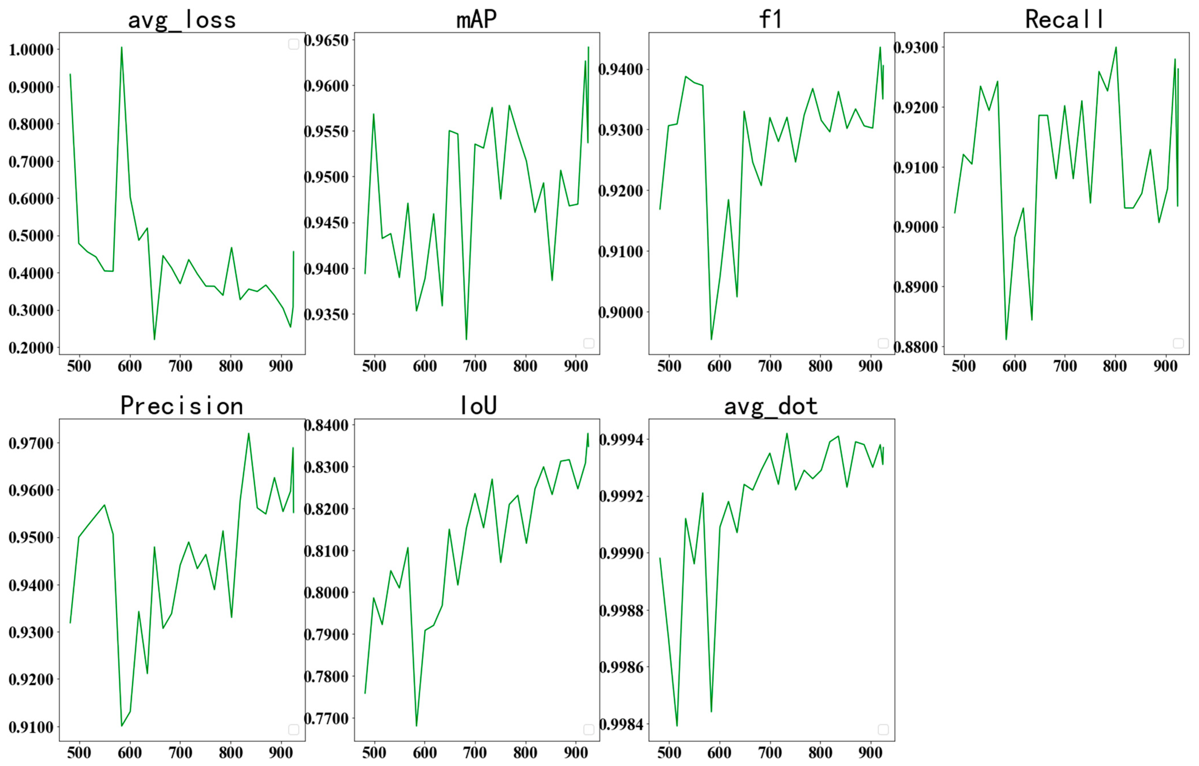
4.3. Result Analysis

(1)
DOTA 1.5
DOTA is the largest dataset for oriented object detection in aerial images with two released versions: DOTA 1.0 and DOTA 1.5. DOTA 1.5 contains 402, 089 instances. Compared with DOTA 1.0, DOTA 1.5 is more challenging but remains stable during training. We experimented with DOTA1.5 data. It contains 16 common categories: Plane (PL), Baseball diamond (BD), Bridge (BR), Ground track field (GTF), Small vehicle (SV), Large vehicle (LV), Ship (SH), Tennis court (TC), Basketball court (BC), Storage tank (ST), Soccer-ball field (SBF), Roundabout (RA), Harbor (HA), Swimming pool (SP), Helicopter (HC), and Container Crane (CC). We test 16 kinds of object extraction experiments on 5000 images of the data set. The experiment is carried out on the image with the pixel size of 896 × 896 on a single NVIDIA Geforce RTX 3090. The changes in each index during the test are shown in Figure 8. As can be seen in Figure 8, the loss is gradually decreasing, while other indexes show an upward trend as a whole. The new index (dot) proposed in this paper shows that the direction estimation result of the object is more accurate.
Various accuracy indexes are shown in Table 1. It can be seen in Table 1 that the mAP value reaches 67.52 and the dot reaches 89.13.
Table 2 lists the dot values of various classes. In the experiment, we think that there are some objects without direction, so their dot values were not calculated. The final dot value is the average dot value of the other 11 kinds of objects, which is as high as 89.13. It can be seen that the proposed direction estimation result is more accurate.
The AP value of each kind of object is shown in Table 3. This paper makes comparisons with the method using DOTA1.5 data as experimental data. As can be seen in Table 3, the AP value of the CC (Container Crane) is low. This is because the number of samples of CC is too small, which leads to the low mAP value of this class and reduces the overall mAP value. However, the final mAP value of the proposed algorithm is still higher than other algorithms.
(2)
HRSC
We experimented with the HRSC data set. We used 617 images to train the mode and carried out ship detection experiments on 444 images. The experiment is carried out on the image with the pixel size of 640 × 640 on a single RTX 2080Ti. The changes in each index during the test are shown in Figure 9. The overall change trend of each accuracy index is similar to that in Figure 8. The loss is gradually decreasing, and other indexes show an upward trend as a whole.
The accuracy of each index is shown in Table 4. In order to verify the effectiveness of the proposed algorithm, it is compared with three other algorithms [3,28,29,30,31] that also experiment with the HSRC data set. The comparison results are shown in Table 4. It can be seen in the table that the mAP values of the five comparison algorithms are lower than 90, while the mAP value of the proposed algorithm is as high as 96.42. The new accuracy index (dot) is as high as 99.93.
(3)
UCAS-AOD
We experimented with the UCAS-AOD dataset [32]. The dataset contains two kinds of objects: a plane and a car. The 1310 images in the data set are segmented according to the size of the network input map 640 × 640 to form 11,131 images in the training set. The 200 pieces of the test set were cut into pieces to form 1706 images, and the experiment was carried out on a single NVIDIA Geforce RTX 3090. In the data set, the aircraft image can clearly determine its direction. However, for the car image, as shown in Figure 10, the human eye can only determine its main axis; that is, the X’ axis and the Y’ axis, but cannot determine the positive direction of the main axis, or, rather, which is the front and which is the rear. Therefore, in the experiment, we think that the head and tail of the car are the overall direction of the car.
The changes in each index during the test are shown in Figure 11. As can be seen in Figure 11, the loss is gradually decreasing, and other indexes show an upward trend as a whole. For the new index (dot) proposed in this paper, it is shown that the direction estimation result of the object is more accurate.
The accuracy of each index is shown in Table 5. It can be seen in the table that the AP values of plane and car proposed by the method are high, so the overall mAP value is up to 99.53. The average dot value is also relatively high. It can be seen that the proposed method can estimate the direction of the object more accurately. In order to further verify the accuracy of the algorithm, it is compared with other methods, and the results are shown in Table 5. In the table, YOLO-v2 [33] uses a horizontal rectangular frame to detect the object, R-DFPN [34] uses a rotating dense feature pyramid to enhance the characteristics of slender targets, DAL [35] improves the efficiency of label allocation through dynamic anchor learning method, DRBox [17] uses a rotating anchor frame to locate the object to improve the detection effect, and S2ARN [36] improves the positioning accuracy of the object frame through two regressions. Through comparison, it can also be seen that the AP value of the proposed method is the highest for both planes and cars. Therefore, the mAP value of the proposed method is also higher than that of other methods.
The visualization results of car detection are shown in Figure 12. In order to verify the effectiveness of the model, it is compared with the literature [27]. In Figure 12, the first row is the experimental results of the proposed algorithm, and the second row is the experimental results of the comparison algorithm. Because it is difficult to distinguish the direction of the head and tail of the car, it is considered that both the head and tail are the direction of the car. It can be seen in the figure that the results of the direction of the object marked by the proposed method meet the requirements. In the experimental results of the comparison algorithm, the direction of the object is any one of the four directions of the rectangular box. It cannot judge the direction of the head or tail of the object, nor can it determine the main axis of the object, which loses the significance of directional object detection.
The visual results of plane object detection are shown in Figure 13. The first row is the detection results of the proposed algorithm, and the second row is the detection results of the comparison algorithm. The planes in the figure are relatively clear. When labeling, the human eye can accurately determine the direction of the nose. Therefore, it can be seen in the figure that the inclined bounding box of the proposed algorithm can accurately locate the object and accurately determine the nose direction of planes. As can be seen in the detection results of the comparison algorithm in the second row, the inclined bounding box can accurately locate the object. However, the object’s direction is any one of the four directions of the rectangular frame, so the main axis of the object and the nose direction of the plane cannot be determined, which completely removes the significance of object’s direction detection.

4.4. Discussion

Detecting the direction of the head or tail of a rotating object is of great significance. For example, in military operations, the next intention of the object can be judged and analyzed. However, it can also be seen in the experiment of the previous section that the direction of the rotating object detected by the current research method of similar work [27] is any one of the four directions of the rectangular frame of the object. It cannot judge the direction of the head or tail of the object, nor can it determine the main axis of the object, which loses the significance of direction object detection. In addition, the mAP obtained from the experimental data of similar works [28] is based on IoU, as shown in Equation (14):
IoU = 1 cos θ + sin θ
Among them, θ is the angle between the prediction object and the ground truth, when the bounding boxes of the predicted value and the ground truth are both squares, as shown in Figure 14.
We get the IOU change curve according to Equation (14), as shown in Figure 15. It can be seen that IOU is always greater than 0.5, which is not affected by θ. That is, when the predicted bounding box is a square, as long as the center point coincides with the ground truth, it will be retained. This calculation method does not consider the accuracy of object direction detection at all and loses the significance of rotating object detection.

5. Conclusions

The paper presents a new object expression method, which uses two components of the direction angle to represent the direction of the object. Then, the geometric model of the object is constrained by combining the coordinates of the center point and the length and width of the object. In order to meet the constraints of two directional components, the network conversion layer is introduced. Then, the output components of the neural network naturally meet the constraints and improve the adaptability of the network model. The proposed method can determine the direction of the main axis of the object while realizing object detection, which changes the idea of traditional methods that only use inclined boxes to represent rotating objects. In future work, the two components of the object direction vector can be extended to the quaternion vector to represent the attitude of the object, so as to realize the detection of the three-dimensional pose of the object.

Author Contributions

Methodology, J.L.; Writing—original draft, H.Z. All authors have read and agreed to the published version of the manuscript.

Funding

This research received no external funding.

Data Availability Statement

Not applicable.

Conflicts of Interest

The authors declare no conflict of interest.

References

  1. Baroud, S.; Chokri, S.; Belhaous, S.; Mestari, M. A brief review of graph convolutional neural network based learning for classifying remote sensing images. Procedia Comput. Sci. 2021, 191, 349–354. [Google Scholar] [CrossRef]
  2. Varadarajan, V.; Garg, D.; Kotecha, K. An efficient deep convolutional neural network approach for object detection and recognition using a multi-Scale anchor box in real-Time. Future Internet 2021, 13, 307. [Google Scholar] [CrossRef]
  3. Liu, J.; Gao, Y. Field Network—A New Method to Detect Directional Object. Sensors 2020, 20, 4262. [Google Scholar] [CrossRef] [PubMed]
  4. Xia, G.S.; Bai, X.; Ding, J.; Zhu, Z.; Belongie, S.; Luo, J.; Datcu, M.; Pelillo, M.; Zhang, L. DOTA: A large-scale dataset for object detection in aerial images. In Proceedings of the IEEE Conference on Computer Vision and Pattern Recognition, Salt Lake City, UT, USA, 18–23 June 2018; pp. 3974–3983. [Google Scholar]
  5. Vicente, S.; Carreira, J.; Agapito, L.; Batista, J. Reconstructing pascal voc. In Proceedings of the IEEE Conference on Computer Vision and Pattern Recognition, Washingtong, DC, USA, 23–28 June 2014; pp. 41–48. [Google Scholar]
  6. Santurkar, S.; Tsipras, D.; Ilyas, A.; Madry, A. How does batch normalization help optimization? Adv. Neural Inf. Process. Syst. 2018, 31, 2488–2498. [Google Scholar]
  7. Wu, Y.; He, K. Group normalization. In Proceedings of the European Conference on Computer Vision (ECCV), Munich, Germany, 8–14 September 2018; pp. 3–19. [Google Scholar]
  8. Lecun, Y.L.; Bottou, L.; Bengio, Y. Gradient-based learning applied to document recognition. Proc. IEEE 1998, 86, 2278–2324. [Google Scholar] [CrossRef] [Green Version]
  9. Krizhev, A.; Suts, I.; Hinton, G.E. Image net classification with deep convolutional neural networks. In Proceedings of the International Conference on Neural Information Processing Systems, Lake Tahoe, NV, USA, 3–6 December 2012; Curran Associates Inc.: Lake Tahoe, NV, USA, 2012; pp. 1097–1105. [Google Scholar]
  10. Simonyan, K.; Zisserman, A. Very deep convolutional networks for large-scale image recognition. In Proceedings of the International Conference on Learning Representations (ICLR), San Diego, CA, USA, 7–9 May 2015; Conference Track Proceedings: San Diego, CA, USA, 2015; pp. 1–13. [Google Scholar]
  11. Szegedy, C.; Liu, W.; Jia, Y.; Sermanet, P.; Reed, S.; Anguelov, D.; Erhan, D.; Vanhoucke, V.; Rabinovich, A. Going deeper with convolutions. In Proceedings of the 2015 IEEE Conference on Computer Vision and Pattern Recognition (CVPR), Boston, MA, USA, 7–12 June 2015; IEEE Computer Society: Washington, DC, USA, 2015; pp. 1–9. [Google Scholar]
  12. He, K.; Zhang, X.; Ren, S. Deep residual learning for image recognition. In Proceedings of the 2016 IEEE Conference on Computer Vision and Pattern Recognition (CVPR), Las Vegas, NV, USA, 27–30 June 2016; IEEE Computer Society: Washington, DC, USA, 2016; pp. 770–778. [Google Scholar]
  13. Girshick, R.; Donahue, J.; Darrell, T. Rich feature hierarchies for accurate object detection and semantic segmentation. In Proceedings of the 2014 IEEE Conference on Computer Vision and Pattern Recognition, Columbus, OH, USA, 23–28 June 2014; IEEE Computer Society: Washington, DC, USA, 2014; pp. 580–587. [Google Scholar]
  14. Girshick, R. Fast R-CNN. In Proceedings of the 2015 IEEE International Conference on Computer Vision (ICCV), Santiago, Chile, 7–13 December 2015; IEEE Computer Society: Washington, DC, USA, 2015; pp. 1440–1448. [Google Scholar]
  15. Ren, S.; He, K.; Girshick, R.; Jun, J. Faster R-CNN: Towards real-time object detection with region proposal networks. IEEE Trans. Pattern Anal. Mach. Intell. 2015, 39, 1137–1149. [Google Scholar] [CrossRef] [PubMed] [Green Version]
  16. Lin, T.; Dollár, P.; Girshick, R. Feature pyramid networks for object detection. In Proceedings of the 2017 IEEE Conference on Computer Vision and Pattern Recognition (CVPR), Honolulu, HI, USA, 21–26 July 2017; IEEE Computer Society: Honolulu, HI, USA, 2017; pp. 936–944. [Google Scholar]
  17. He, K.; Gkioxari, G.; Dollár, P. Mask R-CNN. IEEE Trans. Pattern Anal. Mach. Intell. 2017, 99, 2961–2969. [Google Scholar]
  18. Redmon, J.; Divvala, S.; Girshick, R. You Only Look Once: Unified, Real-Time object detection. In Proceedings of the 2016 IEEE Conference on Computer Vision and Pattern Recognition (CVPR), Las Vegas, NV, USA, 27–30 June 2016; IEEE Computer Society: Washington, DC, USA, 2016; pp. 779–788. [Google Scholar]
  19. Liu, W.; Anguelov, D.; Erhan, D.; Szegedy, C.; Reed, S.; Fu, C.Y.; Berg, A.C. SSD: Single Shot Multi Box Detector. Comput. Vis. 2015, 9905, 21–37. [Google Scholar]
  20. Zhou, Y.; Ye, Q.; Qiu, Q.; Jiao, J. Oriented response networks. In Proceedings of the 2017 IEEE Conference on Computer Vision and Pattern Recognition (CVPR), Honolulu, HI, USA, 21–26 July 2017; IEEE: Piscataway, NJ, USA, 2017; pp. 4961–4970. [Google Scholar]
  21. Cheng, G.; Zhou, P.; Han, J. Learning rotation-invariant convolutional neural networks for object detection in VHR optical remote sensing images. IEEE Trans. Geosci. Remote Sens. 2016, 54, 7405–7415. [Google Scholar] [CrossRef]
  22. Jiang, Y.; Zhu, X.; Wang, X.; Yang, S.; Li, W.; Wang, H.; Fu, P.; Luo, Z. R2CNN: Rotational region CNN for orientation robust scene text detection. arXiv 2017, arXiv:1706.09579. [Google Scholar]
  23. Tang, T.; Zhou, S.; Deng, Z.; Lei, L.; Zou, H. Arbitrary-oriented vehicle detection in aerial imagery with single convolutional neural networks. Remote Sens. 2017, 9, 1170. [Google Scholar] [CrossRef] [Green Version]
  24. Liu, Z.; Wang, H.; Weng, L.; Yang, Y. Ship rotated bounding box space for ship extraction from high-resolution optical satellite images with complex backgrounds. IEEE Geosci. Remote Sens. Lett. 2016, 13, 1074–1078. [Google Scholar] [CrossRef]
  25. Lin, T.Y.; Goyal, P.; Girshick, R.; He, K.; Dollár, P. Focal loss for dense object detection. In Proceedings of the IEEE International Conference on Computer Vision, Venice, Italy, 22–29 October 2017; pp. 2999–3007. [Google Scholar]
  26. Chen, K.; Pang, J.; Wang, J.; Xiong, Y.; Li, X.; Sun, S.; Feng, W.; Liu, Z.; Shi, J.; Ouyang, W.; et al. Hybrid task cascade for instance segmentation. In Proceedings of the IEEE/CVF Conference on Computer Vision and Pattern Recognition, Long Beach, CA, USA, 15–20 June 2019; pp. 4974–4983. [Google Scholar]
  27. Han, J.; Ding, J.; Xue, N.; Xia, G.S. Redet: A rotation-equivariant detector for aerial object detection. In Proceedings of the IEEE/CVF Conference on Computer Vision and Pattern Recognition, Nashville, TN, USA, 20–25 June 2021; pp. 2786–2795. [Google Scholar]
  28. Ding, J.; Xue, N.; Long, Y.; Xia, G.S.; Lu, Q. Learning roi transformer for oriented object detection in aerial images. In Proceedings of the IEEE/CVF Conference on Computer Vision and Pattern Recognition, Long Beach, CA, USA, 16–17 June 2019; pp. 2849–2858. [Google Scholar]
  29. Xu, Y.; Fu, M.; Wang, Q.; Wang, Y.; Chen, K.; Xia, G.S.; Bai, X. Gliding vertex on the horizontal bounding box for multi-oriented object detection. IEEE Trans. Pattern Anal. Mach. Intell. 2020, 43, 1452–1459. [Google Scholar] [CrossRef] [PubMed] [Green Version]
  30. Yang, X.; Liu, Q.; Yan, J.; Feng, Z.; He, T. R3det: Refined single-stage detector with feature refinement for rotating object. arXiv 2019, arXiv:1908.05612. [Google Scholar]
  31. Liao, M.; Zhu, Z.; Shi, B.; Xia, G.S.; Bai, X. Rotation-sensitive regression for oriented scene text detection. In Proceedings of the IEEE Conference on Computer Vision and Pattern Recognition, Salt Lake City, UT, USA, 18–22 June 2018; pp. 5909–5918. [Google Scholar]
  32. Zhu, H.; Chen, X.; Dai, W.; Fu, K.; Ye, Q.; Jiao, J. Orientation robust object detection in aerial images using deep convolutional neural network. In Proceedings of the 2015 IEEE International Conference on Image Processing (ICIP), Quebec City, QC, Canada, 27–30 September 2015; IEEE: Piscataway, NJ, USA, 2015; pp. 3735–3739. [Google Scholar]
  33. Redmon, J.; Farhadi, A. Yolo9000, Better, faster, stronger. In Proceedings of the IEEE Conference on Computer Vision and Pattern Recognition (CVPR), Honolulu, HI, USA, 21–26 July 2017; pp. 7263–7271. [Google Scholar]
  34. Yang, X.; Sun, H.; Fu, K.; Yang, J.; Sun, X.; Yan, M.; Guo, Z. Automatic ship detection in remote sensing images from google earth of complex scenes based on multiscale rotation dense feature pyramid networks. Remote Sens. 2018, 10, 132. [Google Scholar] [CrossRef] [Green Version]
  35. Ming, Q.; Zhou, Z.; Miao, L.; Zhang, H.; Li, L. Dynamic anchor learning for arbitrary-oriented object detection. In Proceedings of the AAAI Conference on Artificial Intelligence, Online, 2–9 February 2021; pp. 2355–2363. [Google Scholar]
  36. Bao, S.; Zhong, X.; Zhu, R.; Zhang, X.; Li, Z.; Li, M. Single shot anchor refinement network for oriented object detection in optical remote sensing imagery. IEEE Access 2019, 7, 87150–87161. [Google Scholar] [CrossRef]
Figure 1. A comparison between traditional bounding box and inclined bounding box. (a) the traditional bounding box. (b) the inclined bounding box.
Remotesensing 14 03523 g001
Figure 2. A schematic diagram of the direction of an object.
Remotesensing 14 03523 g002
Figure 3. A schematic diagram of network structure.
Remotesensing 14 03523 g003
Figure 4. The forward–backward propagation object’s direction calculation.
Remotesensing 14 03523 g004
Figure 5. A schematic diagram of calculating the ground truth.
Remotesensing 14 03523 g005
Figure 6. A flow chart of object detection.
Remotesensing 14 03523 g006
Figure 7. A schematic diagram of calculating the ground truth.
Remotesensing 14 03523 g007
Figure 8. The changes of various indexes of DOTA1.5 dataset during iteration.
Remotesensing 14 03523 g008
Figure 9. The changes of various indexes of HRSC data set during iteration.
Remotesensing 14 03523 g009
Figure 10. Examples of cars in the UCAS-AOD data set.
Remotesensing 14 03523 g010
Figure 11. The changes of various indicators of UCAS-AOD data set during iteration.
Remotesensing 14 03523 g011
Figure 12. The visual results of car detection. The first row is the detection results of the proposed algorithm, and the second row is the detection results of the comparison algorithm.
Remotesensing 14 03523 g012
Figure 13. The visual results of plane detection. The first row is the detection results of the proposed algorithm, and the second row is the detection results of the comparison algorithm.
Remotesensing 14 03523 g013aRemotesensing 14 03523 g013b
Figure 14. The prediction object and ground truth.
Remotesensing 14 03523 g014
Figure 15. The variation curve of IoU.
Remotesensing 14 03523 g015
Table 1. The accuracy indexes of the text results of DOTA 1.5.
Precision IndexesmAPF1IoUDot
propose method67.5270.6172.6489.13
Table 2. The accuracy indexes of the dot of each type of object.
DotPlaneBDBridgeGRFSVLVShipTCBCSTSBFRAHarborSPHCCC
Propose method53.81-76.9680.7799.4799.4899.5799.1798.54-81.06-95.36-96.21-
Table 3. The value of AP of various objects.
MethodPlaneBDBridgeGRFSVLVShipTCBCSTSBFRAHarborSPHCCCmAP
Propose method96.4386.0747.5656.2963.9681.9694.7493.6573.6584.6742.4665.1864.7467.2461170.5667.52
RetinaNet-O [25]71.4377.6442.1264.6544.5356.7973.3190.8476.0259.9646.9569.2459.6564.5248.060.8359.16
FR-O [15]71.8974.4744.4559.8751.2868.9879.3790.7877.3867.5047.7569.7261.2265.2860.471.5462.00
Mask R-CNN [17]76.8473.5149.9057.8051.3171.3479.7590.4674.2166.0746.2170.6163.0764.4657.819.4262.67
HTC [26]77.8073.6751.4063.9951.5473.3180.3190.4875.1267.3448.5170.6364.8464.4855.875.1563.40
ReDet [27]79.2082.8151.9271.4152.3875.7380.9290.8375.8168.6449.2972.0373.3670.5563.3311.5366.86
Table 4. The accuracy indexes of the HRSC data set test result.
Technical IndicatorsmAPDotF1IoU
propose method96.4299.9394.0583.48
RoI Trans. [28]86.2---
GV [29]88.2---
R3Det [30]89.33---
RRD [31]84.3---
CSL [3]89.62---
Table 5. The experimental results of the UCAS-AOD dataset.
MethodAPmAPDot (Each Class)DotIoUF1
PlaneCarPlaneCar
Propose method99.8099.2699.5398.2999.4398.8680.4198.39
YOLO-v2 [33]96.6079.2087.90-----
R-DFPN [34]95.9082.5089.20-----
DAL [35]90.4989.2589.87-----
DRBox [17]94.9085.0089.95-----
S2ARN [36]97.6092.2094.90-----
Publisher’s Note: MDPI stays neutral with regard to jurisdictional claims in published maps and institutional affiliations.

