Technical Note

Coordinated Attitude Control of Spacecraft Formation Flying via Fixed-Time Estimators under a Directed Graph

School of Astronautics, Harbin Institute of Technology, Harbin 150001, China
*
Author to whom correspondence should be addressed.
Remote Sens. 2022, 14(17), 4162; https://doi.org/10.3390/rs14174162
Submission received: 26 July 2022 / Revised: 18 August 2022 / Accepted: 19 August 2022 / Published: 24 August 2022
(This article belongs to the Section Satellite Missions for Earth and Planetary Exploration)

Abstract

:
This paper mainly studies the distributed fixed-time coordinated attitude tracking control problem of spacecraft formation with a dynamic leader spacecraft under directed communication topology. Follower spacecraft cannot communicate directly with the leader spacecraft; therefore, in order to enable them to obtain the target attitude information, a fixed-time state estimator that can be applied to directed graphs is designed. Based on the estimators, a distributed fixed-time attitude tracking control law is proposed. The settling time of the fixed-time algorithm is only related to the parameters of the control law and independent of the initial state; thus, the proposed control law can reduce the influence of the dynamic leader attitude on the spacecraft formation-coordinated attitude tracking control system. Moreover, external disturbances and spacecraft inertia uncertainty were also considered in the design of the control law. The stability of the system was verified by Lyapunov stability theory, and the effectiveness of the control law was verified by numerical simulation.

1. Introduction

To satisfy the requirements of more complex space missions while reducing the cost, the concept of spacecraft formation flying (SSF) has been proposed to replace traditional large spacecraft with a group of cooperating spacecraft that are smaller and cheaper. As a part of SSF, the coordinated attitude synchronization control of spacecraft formation flying is essential for the completion of space missions.
Notably, most existing cooperative attitude control laws can only achieve asymptotic stability or finite-time stability [1,2,3]. Fruitful research results have been achieved in coordinated attitude tracking control. In [4], attitude tracking control was realized on the basis of online learning. In [5], a distributed swarm tracking algorithm was proposed that guarantees global exponential tracking in the absence of velocity measurements. A distributed finite-time tracking control law for nonlinear multiagent systems subject to external disturbances was investigated in [6], and the finite convergence time was explicitly presented. In [7], the proposed distributed finite-time containment control algorithm considered external interference, and the control algorithm guaranteed that the states of the follower converged to the convex hull of the leaders in finite time. An adaptive algorithm was employed to estimate external interference in [8], and based on the estimation, the finite-time control algorithm guaranteed that the system state converged in finite time. Compared with asymptotic stability, finite-time stability control provides a more rapid convergence rate and stronger robustness; however, its settling time is still related to the initial state of the system.
Fixed-time stability theory was proposed in [9]. The settling time of the fixed-time control algorithm is independent of the initial state of the system, which means that the settling time is determined only by the parameters of the fixed-time algorithm. Therefore, the fixed-time control algorithm can provide higher robustness for dynamic attitude tracking control systems. In cases in which the communication topology between spacecraft is an undirected graph, a fixed-time state estimator was designed [10], which could provide accurate leader spacecraft attitude information for follower spacecraft that cannot directly obtain the tracking reference attitude information of the leader. A fixed-time consensus tracking control law was proposed in [11], which guarantees that the consensus tracking errors converge to the origin within a fixed time for a class of second-order multiagent systems under an undirected communication graph. In [12], a distributed fixed-time observer was designed that could estimate the states of the followers. However, the algorithm designed in [10,11,12] cannot be applied when the communication topology is a directed graph. Consequently, in addition to the settling time of the system, more practical conditions should be taken into consideration in the design of control algorithms.
Spacecraft inertia uncertainty is another problem in space missions. The control performance is affected by parameter uncertainties of the system; more seriously, the parameter uncertainties may damage the stability of the system. In [13], the uncertainty of spacecraft inertia was considered, and the adaptive control algorithm was applied to estimate it. The control algorithm guaranteed that all followers asymptotically converged to the dynamic convex hull spanned by dynamic leaders when the communication topology was a directed graph. In [14], bounded external disturbances were considered in the design process of the control algorithm, and the proposed algorithm guaranteed that the tracking error asymptotically converged.
Motivated by the above observations, based on previous work on the cooperative attitude tracking of multiple spacecraft with undirected communication topology [15], this study investigated the problem of distributed fixed-time attitude coordination tracking control for SFF when the communication topology is a directed graph. The distributed fixed-time state estimator and cooperative attitude control law proposed in this paper can extend finite-time control to fixed-time control and extend the communication topology from an undirected graph to a directed graph. First, a distributed fixed-time state estimator was designed that could be applied to a directed graph to estimate the tracking reference attitude information for follower spacecraft when not all the follower spacecraft can communicate with the leader spacecraft directly. Then, the estimated target attitude information can be obtained by the followers. Combined with the adaptive control algorithm to deal with the inertia uncertainty and external disturbance torque, a fixed-time cooperative attitude tracking control law is designed. The principal contributions of this paper are as follows:
(1) In contrast to [6,7], the control law designed in this paper extends finite-time control to fixed-time control so that the settling time is only related to parameters of the control law.
(2) Considering the presence of both inertia uncertainty and external disturbance torque, an adaptive algorithm was employed in the design process of the fixed-time attitude cooperative control law. Compared with [11], the control law proposed in this study considers more practical situations.
(3) Compared with undirected communication topology, the application of directed communication topology is more extensive. In contrast to [10,11], the fixed-time state estimator designed in this study can be applied in cases where the communication topology is a directed graph.
Notation: In this paper, ⊗ represents the Kronecker product. For a vector, x = [ x 1 , . . . , x n ] T , and x and x 1 are the Euclidean norm and Manhattan norm of x, respectively. We define x α = [ x 1 α , . . . , x n α ] T , x α = [ x 1 α , . . . , x n α ] T , and si g α ( x ) = [ sgn ( x 1 ) x 1 α , . . . ,
sgn ( x n ) x n α ] T . For x = [ x 1 , x 2 , x 3 ] T , x × = 0 x 3 x 2 x 3 0 x 1 x 2 x 1 0 . For a matrix A, λ m ( A ) , λ M ( A ) , m ( A ) , and M ( A ) are the minimum eigenvalue, maximum eigenvalue, minimum singular value, and maximum singular value of matrix A, respectively. For a vector x i , x is the column stack vector of x i . For a matrix A i , A is the block diagonal matrix of A i .

2. Preliminaries and Problem Formulation

2.1. Dynamics of Spacecraft Attitude

In this study, the modified Rodrigues parameter (MRP) was applied to describe the attitude of the spacecraft. For leader–follower systems, there is one leader, labeled spacecraft 0, and n follower spacecraft, labeled i = 1 , 2 , . . . , n . The attitude of the ith follower is expressed in [16] as
σ ˙ i = G ( σ i ) ω i ,
where ω i R 3 is the angular velocity of the ith rigid body with respect to the inertial frame, and G ( σ i ) is expressed as
G ( σ i ) = [ 1 σ i 2 2 ] I 3 + σ i × + σ i σ i T ] 2 ,
where I 3 R 3 × 3 is the identity matrix. The matrix G ( σ i ) has the following properties:
Property 1.
det ( G ( σ i ) ) = ( 1 + σ i T σ i ) 3 4 0 .
Property 2.
G T ( σ i ) G ( σ i ) = ( 1 + σ i T σ i 4 ) 2 I 3 .
The dynamics of the ith follower spacecraft are expressed as
J i ω ˙ i = u i + t i ω i × J i ω i ,
where J i R 3 × 3 is the inertia matrix, u i R 3 is the control torque, and t i R 3 is the external disturbance torque. Combining Equation (1) and Equation (3), we can rewrite the attitude dynamics and kinematics equations of the followers in Euler–Lagrange form:
M i ( σ i ) σ ¨ i + C i ( σ i , σ ˙ i ) σ ˙ i = τ i + d i ,
where C i ( σ i , σ ˙ i ) = G T ( σ i ) J i G 1 ( σ i ) G ˙ ( σ i ) G 1 ( σ i ) G T ( σ i ) ( J i ω i ) × G 1 ( σ i ) , τ i = G T ( σ i ) u i , d i = G T ( σ i ) t i , and M i ( σ i ) = G T ( σ i ) J i G 1 ( σ i ) . According to Properties 1 and 2, G ( σ i ) is a nonsingular matrix. For system (4), [17] introduces the following properties:
Property 3.
There are certain constants, C m , C M , and C, such that 0 < C m I 3 M i ( σ i ) C M I 3 and C i ( σ i , σ ˙ i ) C σ ˙ i .
Property 4.
M i ( σ i ) x + C i ( σ i , σ ˙ i ) y = Y i ( σ i , σ ˙ i , x , y ) Θ i , for any x, y R 3 , where Y i ( σ i , σ ˙ i , x , y ) Θ i is a regression matrix and Θ i is a constant parameter vector associated with the inertia matrix of the ith follower.
Assumption 1.
For the attitude of the lead spacecraft, both the attitude change rate and the derivative of the attitude change rate are bounded. It is assumed that σ ˙ 0 N δ 1 and σ ¨ 0 N δ 2 , where N = 1,2,3.
Assumption 2.
There is an unknown upper bound on the external disturbance torque of each follower spacecraft, where it is assumed that d i N k i .

2.2. Graph Theory

In this paper, the communication relationship in spacecraft formation is described by a directed graph. For the details of graph theory, please refer to [18]. A brief overview of graph theory is subsequently presented.
A directed graph, described as G = ( N , E , A ) , is composed of several nodes and edges connecting two nodes, where N = ( n 1 , . . . , n n ) , E N × N , and A = [ a i j ] R n × n are a finite non-empty set of nodes, a set of edges and an adjacency matrix, respectively. If the information of the jth node is available to the ith node, then ( n i , n j ) E , and vice versa. If ( n i , n j ) E , then a i j = 1 . Additionally, a i j = 0 if ( n i , n j ) E . We define the Laplacian matrix L = [ l i j ] R n × n of G, the leader adjacency matrix B = d i a g ( a 10 , a 20 , . . . , a n 0 ) , and H = L + B , where l i i = i j a i j , and l i j = a i j ( i j ) ; a i 0 = 1 if the information of the leader is available to the ith follower, and a i 0 = 0 otherwise.
Assumption 3.
There is a directed spanning tree in the communication topology graph G ¯ for the spacecraft formation flying system.
Lemma 1
([19]). If there is a directed spanning tree in the communication topology G ¯ , then all eigenvalues of H have positive real parts.
Definition 1
([20]). Let Z denote the set of square matrices whose off-diagonal elements are nonpositive, i.e., Z = { H = [ h i j ] R n × n : h i j 0 , i j } . Then, matrix H is called a nonsingular M-matrix if H Z and if all its principal minors are positive.
Lemma 2
([20]). Matrix H Z is a nonsingular M-matrix under one of the following conditions, and the conditions are equivalent:
(a) All eigenvalues of the matrix H have positive real parts;
(b) A positive diagonal matrix F exists such that Q = F H + H T F is a symmetric positive definite matrix.
Lemma 3
([21]). For each real C R n × n , there are real orthogonal matrices Q 1 , Q 2 R n × n such that Q 1 T C Q 2 = d i a g ( 1 ( C ) , . . . , n ( C ) ) is a non-negative diagonal matrix, where 1 ( C ) , . . . , n ( C ) are the singular values and 1 2 ( C ) , . . . , 2 n ( C ) are the eigenvalues of C T C , and the orthonormal columns of Q 1 are eigenvectors of C T C . If C Z n × n is nonsingular, then C + D is nonsingular for every non-negative diagonal matrix D.

2.3. The Concept of Fixed-Time Convergence and Some Lemmas

Consider the following system:
x ˙ = g ( t , x ) , x ( 0 ) = x 0 ,
where x R n and g : R + × R n R n is a nonlinear function, which can be discontinuous. For system (5), the following definitions and lemmas are given:
Definition 2
([9]). System (5) is fixed-time stable if it is finite-time stable and the settling time T ( x 0 ) is uniformly bounded for any initial state, i.e., T max > 0 , such that T ( x 0 ) T max x 0 R n .
Lemma 4
([9]). Consider a radially unbounded continuous function F ( x ) if there are F ( x ) = 0 x = 0 and the solution of (5) satisfies D * F ( x ( t ) ) ( α F a ( x ( t ) ) + β F b ( x ( t ) ) ) c for some α , β , a , b , c > 0 : a c < 1 , b c > 1 , then, the origin is globally fixed-time stable for (5) and the settling time T ( x ) satisfies:
T ( x ) 1 α c ( 1 a c ) + 1 β c ( b c 1 ) x R n ,
where D * F ( t ) = lim Δ 0 + sup f ( t + Δ ) f ( t ) Δ .
Theorem 1.
Based on Lemma 4, if the additional condition c 1 is added, for any solution of (5) that satisfies the inequality D * F ( x ( t ) ) ( α F a ( x ( t ) ) + β F b ( x ( t ) ) ) c + Δ , fixed-time stability still holds for system (5). F ( x ( t ) ) converges to the region F ( x ( t ) ) min [ α 1 a ( Δ ( 1 ς ) ) 1 a c , β 1 b ( Δ ( 1 ψ ) ) 1 b c ] in T ( x ) max [ 1 ς α c ( 1 a c ) + 1 β c ( b c 1 ) , 1 α c ( 1 a c ) + 1 ψ β c ( b c 1 ) ] , where 0 < ς < 1 and 0 < ψ < 1 .
Proof. 
D * F ( x ( t ) ) ( α F a ( x ( t ) ) + β F b ( x ( t ) ) ) c + Δ α c F a c ( x ( t ) ) β c F b c ( x ( t ) ) + Δ ς α c F a c ( x ( t ) ) β c F b c ( x ( t ) ) [ ( 1 ς ) α c F a c ( x ( t ) ) Δ ]
If α c ( 1 ς ) F a c ( x ( t ) ) Δ > 0 F ( x ( t ) ) > α 1 a ( Δ ( 1 ς ) ) 1 a c , then according to lemma 4, F ( x ( t ) ) converges to the region F ( x ( t ) ) α 1 a ( Δ ( 1 ς ) ) 1 a c in T ( x ) 1 ς α c ( 1 a c ) + 1 β c ( b c 1 ) . Similarly, D * F ( x ( t ) ) α c F a c ( x ( t ) ) β c F b c ( x ( t ) ) + Δ can be rewritten as D * F ( x ( t ) ) α k F a c ( x ( t ) ) ψ β c F b c ( x ( t ) ) [ ( 1 ψ ) β c F b c ( x ( t ) ) Δ ] , and F ( x ( t ) ) converges to the region F ( x ( t ) ) β 1 b ( Δ ( 1 ψ ) ) 1 b c in T ( x ) 1 α c ( 1 a c ) + 1 ψ β c ( b c 1 ) . This completes the proof of Theorem 1. □
Lemma 5
([22]). Let ξ 1 , ξ 2 , . . . , ξ n 0 ; then,
i = 1 n ξ i p ( i = 1 n ξ i ) p , i f 0 < p 1 , i = 1 n ξ i p n 1 p ( i = 1 n ξ i ) p , i f p > 1 .
Lemma 6
([23]). For any a , b R n and any symmetric positive definite matrix Φ R n × n ,
2 a T b a T Φ 1 a + b T Φ b .

2.4. Problem Formulation

This study aimed to design a distributed fixed-time attitude tracking control algorithm for a spacecraft formation flying based on fixed-time state estimators which are available for a directed graph, G ¯ . The tracking error of attitude and the derivative of attitude are defined as
e 1 i = σ i σ 0 ,
e 2 i = σ ˙ i σ ˙ 0 .
The distributed fixed-time control algorithm, τ i , presented in this paper aimed to achieve fixed-time convergence for e 1 i and e 2 i , which means that attitude synchronization with the leader spacecraft can be achieved within a fixed time for any follower spacecraft.

3. Design of the Control Law

3.1. Distributed Fixed-Time Estimator Design

In this section, distributed fixed-time estimators that can be applied to directed communication topology are proposed, and with the aim of obtaining accurate estimates of σ 0 and σ ˙ 0 for each follower. It is obvious that H Z in Definition 1 is a nonsingular M-matrix according to Lemma 2. Under Assumption 3, Lemma 1, and Lemma 2, a positive diagonal matrix F = d i a g ( f 1 , f 2 , . . . , f n ) exists such that Q = F H + H T F is a symmetric positive definite matrix. σ ^ i and v ^ i are the estimates of σ 0 and σ ˙ 0 , respectively. The estimators are designed as
σ ^ ˙ i = α 1 sig r 1 [ j = 1 n f i a i j ( σ ^ i σ ^ j ) + f i a i 0 ( σ ^ i σ 0 ) ] α 2 sig r 2 [ j = 1 n f i a i j ( σ ^ i σ ^ j ) + f i a i 0 ( σ ^ i σ 0 ) ] β 1 sign [ j = 1 n f i a i j ( σ ^ i σ ^ j ) + f i a i 0 ( σ ^ i σ 0 ) ]
v ^ ˙ i = α 1 sig r 1 [ j = 1 n f i a i j ( v ^ i v ^ j ) + f i a i 0 ( v ^ i σ ˙ 0 ) ] α 2 sig r 2 [ j = 1 n f i a i j ( v ^ i v ^ j ) + f i a i 0 ( v ^ i σ ˙ 0 ) ] β 2 sign [ j = 1 n f i a i j ( v ^ i v ^ j ) + f i a i 0 ( v ^ i σ ˙ 0 ) ]
where α 1 > 0 , α 2 > 0 , 0 < γ 1 < 1 , γ 2 > 1 , β 1 δ 1 , and β 2 δ 2 . The difference between the estimated state value and the actual state value is defined as
σ ˜ i = σ ^ i σ 0 , v ˜ i = v ^ i σ ˙ 0 .
Theorem 2.
Under Assumptions 1 and 3, considering the SSF system (4) under G ¯ , the estimators (12) and (13) guarantee t h a t   σ ˜ i and v ˜ i have fixed time convergence and the settling time is T 1 λ M ( Q ) γ 1 + 1 2 α 1 2 γ 1 m ( H T F ) γ 1 + 1 ( 1 γ 1 ) + λ M ( Q ) γ 2 + 1 2 α 2 2 γ 2 ( 3 n ) 1 γ 2 2 m ( H T F ) γ 2 + 1 ( γ 2 1 ) .
Proof. 
Define σ ˜ = [ σ ˜ 1 T , σ ˜ 2 T , . . . , σ ˜ n T ] T = [ σ ˜ 11 , . . . , σ ˜ i N , . . . , σ ˜ n 3 ] T , i = 1 , 2 , . . . , n , and N = 1 , 2 , 3 . Based on Lemma 2, consider the Lyapunov function candidate as V 1 = 1 4 σ ˜ T [ ( F I 3 ) ( H I 3 ) + ( H I 3 ) T ( F I 3 ) ] σ ˜ . Q = F H + H T F is a symmetric positive definite matrix; therefore, according to the properties of the Kronecker product, ( F I 3 ) ( H I 3 ) + ( H I 3 ) T ( F I 3 ) = ( F H ) I 3 + ( H T F ) I 3 = Q I 3 is a symmetric positive definite matrix. There is certainly an orthogonal matrix such that
V 1 = 1 4 σ ˜ T [ ( F I 3 ) ( H I 3 ) + ( H I 3 ) T ( F I 3 ) ] σ ˜ = 1 4 σ ˜ T U T d i a g ( λ 1 , λ 2 , . . . , λ 3 n ) U σ ˜ = 1 4 i = 1 3 n λ i b i 2
where b = [ b 1 , . . . , b 3 n ] T = U σ ˜ , λ i > 0 , which is the eigenvalue of the matrix ( F I 3 ) ( H I 3 ) + ( H I 3 ) T ( F I 3 ) . It is obvious that σ ˜ T [ ( F I 3 ) ( H I 3 ) ] σ ˜ = σ ˜ T [ ( H I 3 ) T ( F I 3 ) ] σ ˜ . We can also obtain V 1 = 1 2 σ ˜ T [ ( H I 3 ) T ( F I 3 ) ] σ ˜ . Taking the time derivative of V 1 ,
V ˙ 1 = σ ˜ T ( H I 3 ) T ( F I 3 ) ( σ ^ ˙ 1 n σ ˙ 0 ) = α 1 σ ˜ T ( H I 3 ) T ( F I 3 ) sig r 1 [ ( F I 3 ) ( H I 3 ) σ ˜ ] α 2 σ ˜ T ( H I 3 ) T ( F I 3 ) sig r 2 [ ( F I 3 ) ( H I 3 ) σ ˜ ] β 1 σ ˜ T ( H I 3 ) T ( F I 3 ) sign [ ( F I 3 ) ( H I 3 ) σ ˜ ] σ ˜ T ( H I 3 ) T ( F I 3 ) ( 1 n σ ˙ 0 ) ,
where 1 n = [ 1 , . . . , 1 ] T ; we can define P = ( F I 3 ) ( H I 3 ) σ ˜ = [ p 11 , p 12 , p 13 , . . . , p n 1 , p n 2 , p n 3 ] T . Based on Lemma 5, we have
V ˙ 1 = α 1 i = 1 n N = 1 3 ( p i N 2 ) γ 1 + 1 2 α 2 i = 1 n N = 1 3 ( p i N 2 ) γ 2 + 1 2 β 1 i = 1 n N = 1 3 p i N i = 1 n N = 1 3 p i N σ ˙ 0 N α 1 [ i = 1 n N = 1 3 ( p i N 2 ) ] γ 1 + 1 2 i = 1 n N = 1 3 p i N σ ˙ 0 N α 2 ( 3 n ) 1 γ 2 2 [ i = 1 n N = 1 3 ( p i N 2 ) ] γ 2 + 1 2 β 1 i = 1 n N = 1 3 p i N α 1 ( P 2 ) γ 1 + 1 2 α 2 ( 3 n ) 1 γ 2 2 ( P 2 ) γ 2 + 1 2 ( β 1 δ 1 ) i = 1 n N = 1 3 p i N
According to Lemmas 1–3, H and F are nonsingular, and the singular value i of matrix ( H I 3 ) T ( F I 3 ) is positive. There are certainly orthogonal matrices, U 1 and U 2 , such that
( H I 3 ) T ( F I 3 ) = U 1 T d i a g ( 1 , 2 , . . . , 3 n ) U 2
Then, we can obtain
P 2 = P T P = σ ˜ T ( H I 3 ) T ( F I 3 ) ( F I 3 ) ( H I 3 ) σ ˜ = σ ˜ T U 1 T d i a g ( 1 , . . . , 3 n ) U 2 U 2 T d i a g ( 1 , . . . , 3 n ) U 1 σ ˜ = σ ˜ T U 1 T d i a g ( 1 2 , 2 2 , . . . , 3 n 2 ) U 1 σ ˜ = i = 1 3 n i 2 c i 2
where c = [ c 1 , . . . , c 3 n ] T = U 1 σ ˜ , according to the property of the Kronecker product, λ m [ ( F I 3 ) ( H I 3 ) + ( H I 3 ) T ( F I 3 ) ] = λ m ( Q ) , λ M [ ( F I 3 ) ( H I 3 ) + ( H I 3 ) T ( F I 3 ) ] = λ M ( Q ) , m [ ( H I 3 ) T ( F I 3 ) ] = m [ H T F ] and M [ ( H I 3 ) T ( F I 3 ) ] = M ( H T F ) . Then, we can obtain 1 4 λ m ( Q ) i = 1 3 n b i 2 V 1 1 4 λ M ( Q ) i = 1 3 n b i 2 and m ( H T F ) 2 i = 1 3 n c i 2 P 2 M ( H T F ) 2 i = 1 3 n c i 2 . U and U 1 are real orthogonal matrices; therefore, b 2 = σ ˜ T U T U σ ˜ = i = 1 3 n b i 2 = c 2 = σ ˜ T U 1 T U 1 σ ˜ = i = 1 3 n c i 2 , and we can obtain
4 m ( H T F ) 2 λ M ( Q ) V 1 P 2 4 M ( H T F ) 2 λ m ( Q ) V 1 .
Combining Equations (17) and (20),
V ˙ 1 α 1 [ 4 m ( H T F ) 2 λ M ( Q ) ] ( V 1 ) γ 1 + 1 2 γ 1 + 1 2 α 2 ( 3 n ) 1 γ 2 2 [ 4 m ( H T F ) 2 λ M ( Q ) ] ( V 1 ) γ 2 + 1 2 γ 2 + 1 2
According to Lemma 4, after setting time T 1 , σ ˜ i will converge to zero, where T 1 is
T 1 λ M ( Q ) γ 1 + 1 2 α 1 2 γ 1 m ( H T F ) γ 1 + 1 ( 1 γ 1 ) + λ M ( Q ) γ 2 + 1 2 α 2 2 γ 2 ( 3 n ) 1 γ 2 2 m ( H T F ) γ 2 + 1 ( γ 2 1 ) .
The proofs for the two estimators are similar: Theorem 2 is proven. □

3.2. Distributed Fixed-Time Control Law Design

Based on the previous distributed fixed-time state estimator, a distributed fixed-time cooperative attitude tracking control law is detailed in this section. The differences in attitude and attitude change rates between follower spacecrafts are described as
e 1 i j = σ i σ j , e 2 i j = σ ˙ i σ ˙ j .
Integrated attitude error is defined as
θ 1 i = j = 1 n a i j e 1 i j + e 1 i = j = 1 n a i j ( σ i σ j ) + ( σ i σ 0 ) = j = 1 n a i j [ ( σ i σ 0 ) ( σ j σ 0 ) ] + ( σ i σ 0 )
θ 2 i = j = 1 n a i j e 2 i j + e 2 i = j = 1 n a i j ( σ ˙ i σ ˙ j ) + ( σ ˙ i σ ˙ 0 ) = j = 1 n a i j [ ( σ ˙ i σ ˙ 0 ) ( σ ˙ j σ ˙ 0 ) ] + ( σ ˙ i σ ˙ 0 )
Define e 1 = [ e 11 T , e 12 T , . . . , e 1 n T ] T , θ 1 = [ θ 11 T , θ 12 T , . . . , θ 1 n T ] T = [ ( L + I n ) I 3 ] e 1 , e 2 = [ e 21 T ,
e 22 T , . . . , e 2 n T ] T , and θ 2 = [ θ 21 T , θ 22 T , . . . θ 2 n T ] T = [ ( L + I n ) I 3 ] e 2 . Based on Lemma 3, there is certainly a non-negative diagonal matrix, D, such that L + I n = H + D is nonsingular. The analysis process is similar to that of ( H I 3 ) T ( F I 3 ) in Theorem 2, λ m { [ ( L + I n ) I 3 ) ] T [ ( L + I n ) I 3 ] } = λ m [ ( L + I n ) T ( L + I n ) ] , m [ ( L + I n ) I 3 ] = m [ L + I n ] > 0 and λ m [ ( L + I n ) T ( L + I n ) ] = m 2 ( L + I n ) . We construct auxiliary variables θ ^ 1 i = j = 1 n a i j [ ( σ i σ ^ i ) ( σ j σ ^ i ) ] + ( σ i σ ^ i ) , σ ˙ r i and s ^ i as
σ ˙ r i = v ^ i j = 1 n a i j ( σ ˙ i σ ˙ j ) μ 1 sig φ 1 θ ^ 1 i μ 2 χ ^ i
s ^ i = σ ˙ i σ ˙ r i
with
χ ^ i = sig φ 2 θ ^ 1 i , θ ^ 1 i N Δ 1 ν 1 θ ^ 1 i + ν 2 sig 2 θ ^ 1 i , θ ^ 1 i N < Δ 1
where φ 1 > 1 and 0 < φ 2 < 1 ; Δ 1 is a small positive constant such that ν 1 = ( 2 φ 2 ) Δ 1 φ 2 1 and ν 2 = ( φ 2 1 ) Δ 1 φ 2 2 . It was proven in Theorem 1 that σ ^ i = σ 0 , v ^ i = σ ˙ 0 and θ ^ 1 i = θ 1 i in a fixed time; thus, after T 1 , we can obtain
s i = s ^ i = θ 2 i + μ 1 sig φ 1 ( θ 1 i ) + μ 2 sig φ 2 ( θ 1 i ) , θ 1 i N Δ 1 θ 2 i + μ 1 sig φ 1 ( θ 1 i ) + μ 2 [ ν 1 θ 1 i + ν 2 θ 1 i 2 sgn ( θ 1 i ) ] , θ 1 i N < Δ 1
Remark 1.
For the design of χ ^ i and σ ˙ r i , s i is continuous, and the singularity drawback can be resolved. The boundedness of v ^ i is proven in Theorem 2; moreover, according to Equation (13) and Equation (26), the boundedness of v ^ ˙ i , σ ˙ r i and σ ¨ r i can be obtained.
By Property 2, combining Equation (4),
M i ( σ i ) σ ¨ r i + C i ( σ i , σ ˙ i ) σ ˙ r i = Y i ( σ i , σ ˙ i , σ ¨ r i , σ ˙ r i ) Θ i ,
M i ( σ i ) s ˙ i + C i ( σ i , σ ˙ i ) s i = τ i + d i Y i Θ i .
where Y i = Y i ( σ i , σ ˙ i , σ ¨ r i , σ ˙ r i ) is bounded according to the boundedness of σ ˙ r i and σ ¨ r i .
Considering the external interference and parameter uncertainty of the system, the distributed fixed-time attitude tracking control law is proposed as
τ i = C i ( σ i , σ ˙ i ) s i + Y i Θ ^ i κ 1 M i ( σ i ) s i g α q 1 ( s i ) κ 2 M i ( σ i ) s i g α q 2 ( s i ) k ^ i s g n [ s i T M i 1 ( σ i ) ] T
where Θ ^ ˙ i = Y i T [ M i T ( σ i ) ] s i and k ^ ˙ i = s i T M i 1 ( σ i ) 1 are the derivatives for the estimates of Θ i and k i , respectively. κ 1 > 0 , κ 2 > 0 , 0 < α q 1 < 1 , α q 2 > 1 , and α > 1 .
Theorem 3.
Considering the spacecraft formation flying system (4) with a directed graph under Assumption 1 and Assumption 2, control law (32)) guarantees that e 1 and e 2 converge to the regions e 1 3 i = 1 n Δ θ 1 i 2 m ( L + I n ) and e 2 3 i = 1 n Δ θ 2 i 2 m ( L + I n ) , respectively, with a fixed setting time T = T 1 + T 2 + T 3 .
Proof. 
First, for the proof of boundedness for the related variables, substituting Equation (32) into Equation (31), we have
M ( σ ) s ˙ = Y Θ ˜ + d κ 1 M ( σ ) sig α q 1 ( s ) κ 2 M ( σ ) sig α q 2 ( s ) k ^ I 3 sgn [ s T M 1 ( σ ) ] T
where k ˜ i = k i k ^ i , Θ ˜ i = Θ ^ i Θ i .
Consider Lyapunov function V 2 as
V 2 = 1 2 s T s + 1 2 i = 1 n k ˜ 2 i + 1 2 Θ ˜ T Θ ˜
Taking the time derivative of the Lyapunov function V 2 ,
V ˙ 2 = s T s ˙ + Θ ˜ T Θ ˜ ˙ + i = 1 n k ˜ i k ˜ ˙ i = s T M 1 ( σ ) { κ 1 M ( σ ) sig α q 1 ( s ) κ 2 M ( σ ) sig α q 2 ( s ) k ^ I 3 sgn [ s T M 1 ( σ ) ] T + Y Θ ˜ + d } Θ ˜ T Θ ^ ˙ i = 1 n k ˜ i k ^ ˙ i = κ 1 s T sig α q 1 ( s ) κ 2 s T sig α q 2 ( s ) + s T M 1 ( σ ) d + Θ ˜ T { Y T [ M T ( σ ) ] s Θ ^ ˙ } i = 1 n k ^ i s i T M i 1 ( σ i ) 1 i = 1 n k ˜ i k ^ ˙ i = κ 1 s T sig α q 1 ( s ) κ 2 s T sig α q 2 ( s ) + s T M 1 ( σ ) d i = 1 n k ^ i s i T M i 1 ( σ i ) 1 i = 1 n k ˜ i s i T M i 1 ( σ i ) 1 ( κ 1 i = 1 n N = 1 3 s i N 1 + α q 1 + κ 2 i = 1 n N = 1 3 s i N 1 + α q 2 )
This completes the proof of boundedness for s, Θ ˜ , and k ˜ . □
Second, for the proof of fixed-time stability for Equation (33), consider the Lyapunov function candidate V 3 as
V 3 = 1 2 s T s .
Taking the time derivative of V 3 , based on Lemma 5 and 6, we can obtain
V ˙ 3 = s T s ˙ = s T M 1 ( σ ) { κ 1 M ( σ ) sig α q 1 ( s ) κ 2 M ( σ ) sig α q 2 ( s ) k ^ I 3 sgn [ s T M 1 ( σ ) ] T + Y Θ ˜ + d } = κ 1 s T sig α q 1 ( s ) κ 2 s T sig α q 2 ( s ) + s T M 1 ( σ ) ( Y Θ ˜ + d ) i = 1 n s i T M i 1 ( σ i ) 1 2 ( κ 1 i = 1 n N = 1 3 s i N 1 + α q 1 + κ 2 i = 1 n N = 1 3 s i N 1 + α q 2 ) i = 1 n s i T M i 1 ( σ i ) 1 2 + i = 1 n s i T M i 1 ( σ i ) 2 + i = 1 n Y i Θ ˜ i + d i 2 { 2 3 + α q 1 2 α 2 α κ 1 1 α [ 1 2 i = 1 n N = 1 3 ( s i N 2 ) ] 1 + α q 1 2 α + 2 3 + α q 2 2 α 2 α κ 2 1 α ( 3 n ) 1 α q 2 2 α [ 1 2 i = 1 n N = 1 3 ( s i N 2 ) ] 1 + α q 2 2 α } α + i = 1 n Y i Θ ˜ i + d i 2
Y i , Θ ˜ i , and d i are bounded; therefore, a constant η exists such that i = 1 n Y i Θ ˜ i + d i 2 η ; then, it can be obtained that
V ˙ 3 [ 2 3 + α q 1 2 α 2 α κ 1 1 α V 3 1 + α q 1 2 α + 2 3 + α q 2 2 α 2 α κ 2 1 α ( 3 n ) 1 α q 2 2 α V 3 1 + α q 2 2 α ] α + η
According to Lemma 4 and Theorem 1, s converges to the region
s Δ s = min { 2 α 1 1 + α q 1 [ η ( 1 ς 1 ) κ 1 ] 1 α q 1 + 1 , 2 α 1 1 + α q 2 [ η ( 1 ς 2 ) κ 2 ( 3 n ) 1 α q 2 2 ] 1 α q 2 + 1 }
where 0 < ς 1 < 1 and 0 < ς 2 < 1 . This also means that we have s i N Δ s in the fixed time as
T 2 = max ( T 21 , T 22 ) max [ 2 2 α 1 α q 1 2 ς 1 κ 1 ( 1 α q 1 ) + 2 2 α 1 α q 2 2 κ 2 ( 3 n ) 1 α q 2 2 ( α q 2 1 ) , 2 2 α 1 α q 1 2 κ 1 ( 1 α q 1 ) + 2 2 α 1 α q 2 2 ς 2 κ 2 ( 3 n ) 1 α q 2 2 ( α q 2 1 ) ]
Therefore, the following equations are obtained after T 1 + T 2 :
s i N = θ 2 i N + μ 1 sig φ 1 ( θ 1 i N ) + μ 2 sig φ 2 ( θ 1 i N ) , θ 1 i N Δ 1 θ 2 i N + μ 1 sig φ 1 ( θ 1 i N ) + μ 2 [ ν 1 θ 1 i N + ν 2 θ 1 i N 2 sgn ( θ 1 i N ) ] , θ 1 i N < Δ 1
For θ 1 i N Δ 1 ,
θ 2 i N = μ 1 sig φ 1 ( θ 1 i N ) μ 2 sig φ 2 ( θ 1 i N ) + s i N μ 1 sig φ 1 ( θ 1 i N ) μ 2 sig φ 2 ( θ 1 i N ) + Δ s
Consider the Lyapunov function candidate V 4 as
V 4 = 1 2 θ 1 i N 2 .
Taking the time derivative of the Lyapunov function V 4 ,
V ˙ 4 = θ 1 i N θ 2 i N = μ 1 2 φ 1 + 1 2 [ 1 2 ( θ 1 i N ) 2 ] φ 1 + 1 2 μ 2 2 φ 2 + 1 2 [ 1 2 ( θ 1 i N ) 2 ] φ 2 + 1 2 + s i N θ 1 i N μ 1 2 φ 1 + 1 2 V 4 φ 1 + 1 2 μ 2 2 φ 2 + 1 2 V 4 φ 2 + 1 2 + Δ s θ 1 i N
Then, according to Lemma 4 and Theorem 1, the integrated attitude error θ 1 i N converges to the region
θ 1 i N Δ θ 1 i = min [ ( Δ s ( 1 ς 3 ) μ 1 ) 1 φ 1 , ( Δ s ( 1 ς 4 ) μ 2 ) 1 φ 2 ]
where 0 < ς 3 < 1 and 0 < ς 4 < 1 . Based on Equation (42), the integrated attitude error θ 2 i N converges to the region
θ 2 i N μ 1 θ 1 i N φ 1 + μ 2 θ 1 i N φ 2 + Δ s μ 1 Δ θ 1 i φ 1 + μ 2 Δ θ 1 i φ 2 + Δ s = Δ θ 2 i
Moreover, the settling time of θ 1 i N and θ 2 i N is
T 3 = max ( T 31 , T 32 ) = max [ 2 1 φ 1 2 ς 3 μ 1 ( φ 1 1 ) + 2 1 φ 2 2 u 2 ( 1 φ 2 ) , 2 1 φ 1 2 μ 1 ( φ 1 1 ) + 2 1 φ 2 2 ς 4 u 2 ( 1 φ 2 ) ]
for θ 1 i N < Δ 1 ,
θ 2 i N + μ 1 sig φ 1 ( θ 1 i N ) + μ 2 [ ν 1 θ 1 i N + ν 2 θ 1 i N 2 sgn ( θ 1 i N ) ] = Δ s
θ 2 i N μ 1 Δ 1 φ 1 + Δ s + μ 2 ( 2 φ 2 ) Δ 1 θ 1 i N + sgn ( θ 1 i N ) θ 2 1 i N ( φ 2 1 ) Δ 1 φ 2 2 μ 1 Δ 1 φ 1 + μ 2 Δ 1 φ 2 + Δ s = Δ 2
Notably, the design of parameter Δ 1 > 0 here aims to avoid the singularity of the auxiliary variable σ ˙ r i , and parameter Δ 1 directly affects the convergence accuracy of the system. Therefore, Δ 1 should be reasonably adjusted according to the actual control process. Designing Δ 1 as a small permissible constant ensures that Δ 1 < Δ θ 1 i and Δ 2 < Δ θ 2 i while preventing the singularity problem from occurring. Thus, the states of the system converge to a small permissible range of the equilibrium point within a fixed time. Then, after T = T 1 + T 2 + T 3 , we obtain
m 2 ( L + I n ) e 1 T e 1 e 1 T [ ( L + I n ) I 3 ) ] T [ ( L + I n ) I 3 ] e 1 = θ 1 T θ 1 3 i = 1 n Δ θ 1 i 2
The analysis of e 1 and e 2 is the same. Then, e 1 and e 2 will converge to the regions
e 1 3 i = 1 n Δ θ 1 i 2 m ( L + I n ) , e 2 3 i = 1 n Δ θ 2 i 2 m ( L + I n ) ,
respectively, in a fixed time T = T 1 + T 2 + T 3 . This completes the proof of Theorem 3. In summary, the control algorithm designed in this paper includes fixed-time state estimators that can be applied in a directed communication topology, adaptive control law, and fixed-time attitude tracking control algorithm. The schematic diagram of the control law is shown in Figure 1.

4. Simulation Results

In this section, the results of the numerical simulation for verifying the effectiveness of the state estimator and control law designed in this paper are presented. The directed communication topology is described in Figure 2, where H = 3 0 1 1 0 1 0 0 1 0 1 0 0 1 0 1 .
The initial conditions of the follower spacecraft are listed in Table 1. The dynamic leader spacecraft attitude, σ 0 , is assumed to be [ 0.03 sin ( 0.1 t ) , 0 . 02 cos ( 0 . 1 t ) , 0.04 sin ( 0 . 1 t ) ] T . The parameters of the distributed estimator (12) and (13), the auxiliary variable σ ˙ r i , and the control law (32) are set as F = d i a g ( f 1 , f 2 , f 3 , f 4 ) = d i a g ( 1 , 1 , 1 , 1 ) , α 1 = α 2 = 2 , κ 1 = 1.27 , κ 2 = 1 , γ 1 = 0.7 , γ 2 = 1.2 , μ 1 = 1 , μ 2 = 1 , φ 1 = 1 . 2 , φ 2 = 0 . 7 , β 1 = 4 × 10 3 , β 2 = 4 × 10 4 , Δ 1 = 1 × 10 5 , α = 1.2 , q 1 = 0.3 , and q 2 = 1.67 . The external disturbance torque is set as [ 0.03 sin ( 0.1 t ) , 0 . 04 cos ( 0 . 1 t ) , 0.05 sin ( 0 . 1 t ) ] T N·m. The additional uncertain inertia matrix is set as 0.1 sin ( 0.1 t ) 0.01 sin ( 0.1 t ) 0.01 sin ( 0.1 t ) 0.01 sin ( 0.1 t ) 0.15 sin ( 0.1 t ) 0.01 sin ( 0.1 t ) 0.01 sin ( 0.1 t ) 0.01 sin ( 0.1 t ) 0.1 cos ( 0.1 t ) kg · m 2 . Considering that the control torque which the spacecraft actuator can provide is limited, in the simulation, the saturated control torque was set as 35 N·m. The simulation results are shown in Figure 3, Figure 4, Figure 5, Figure 6, Figure 7 and Figure 8.
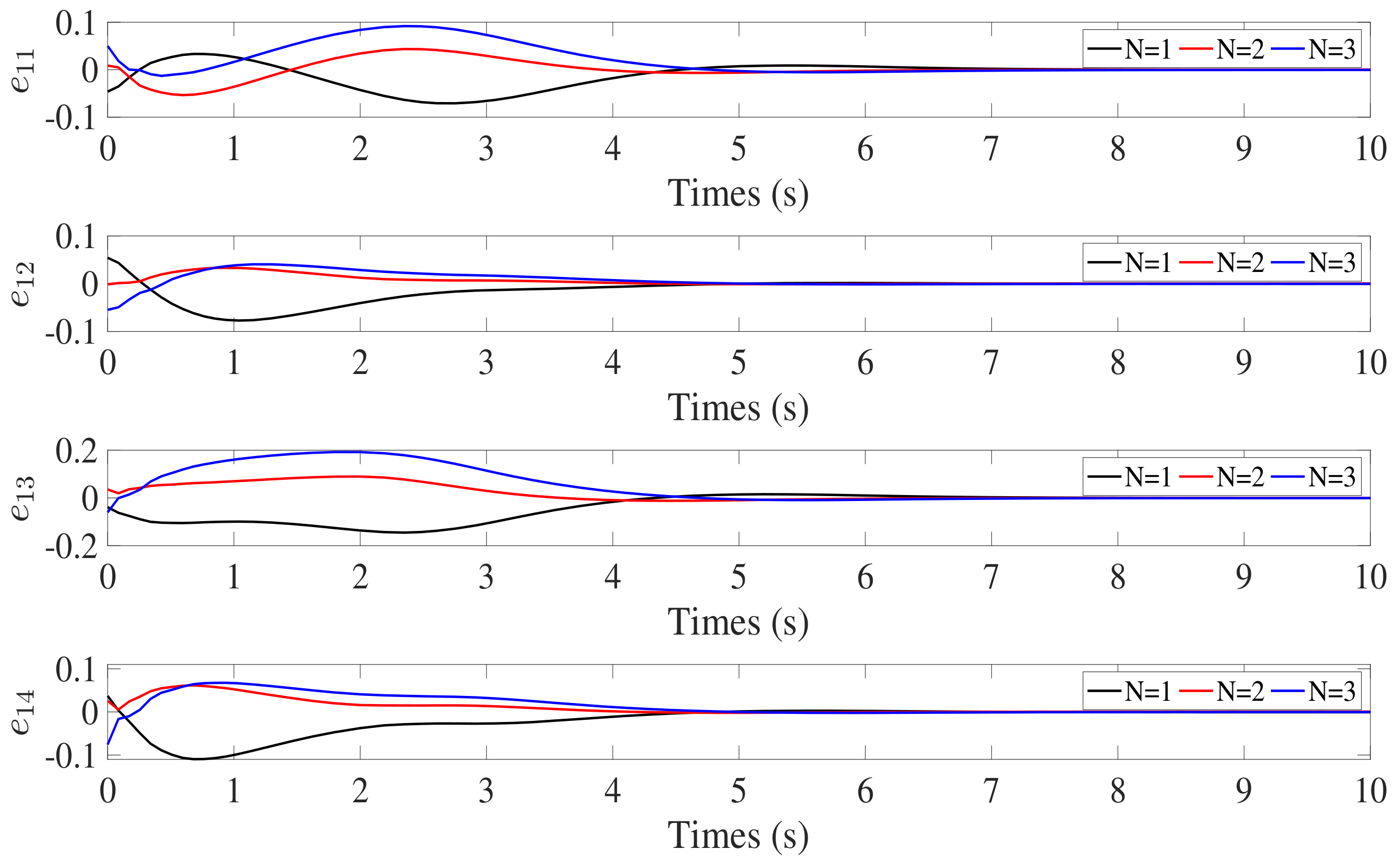
In order to demonstrate the effectiveness of the proposed fixed-time state estimator, the control law proposed in [24] is compared in the simulation. In [24], all the follower spacecraft could obtain the attitude information of the leader spacecraft under the directed communication topology. However, the control performance is not ideal in the situation proposed in this paper, because not all follower spacecraft can communicate with the leader spacecraft directly. In the simulation, the attitude information of the adjacent spacecraft was taken as the target attitude for the follower spacecraft which cannot communicate directly with the leader spacecraft. The simulation results are shown in Figure 3. The follower spacecraft could finally achieve attitude synchronization; however, in the process of attitude tracking error convergence, the control effect is not excellent, and the tracking error of the follower spacecraft may increase repeatedly. Comparing the cooperative attitude control law combined with the fixed-time state estimator proposed in this paper, the control performance is shown in Figure 4. It can be seen that the control law proposed in this paper can guarantee that each follower spacecraft achieves attitude synchronization faster, and the tracking error will not increase repeatedly. This is because in cooperative attitude control, the controlled variable of the controller of the follower spacecraft includes the attitude information of the adjacent spacecraft, and the attitude tracking error of the follower spacecraft will be affected by the attitude tracking error of its adjacent spacecraft. Therefore, it is necessary to obtain an accurate target attitude for each follower spacecraft.
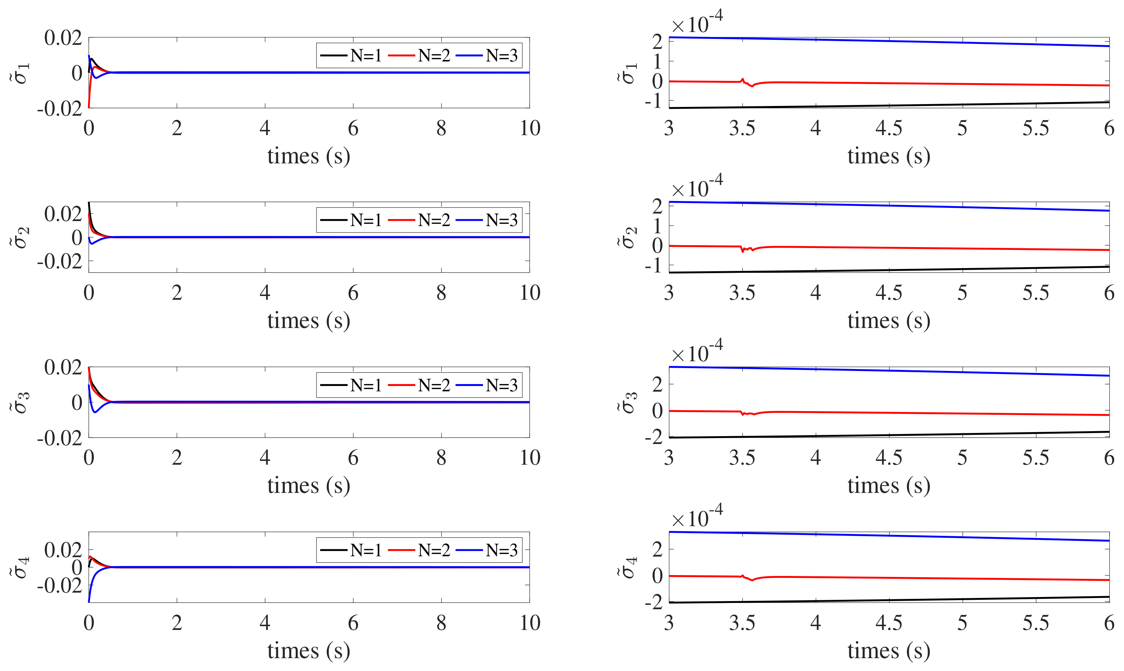
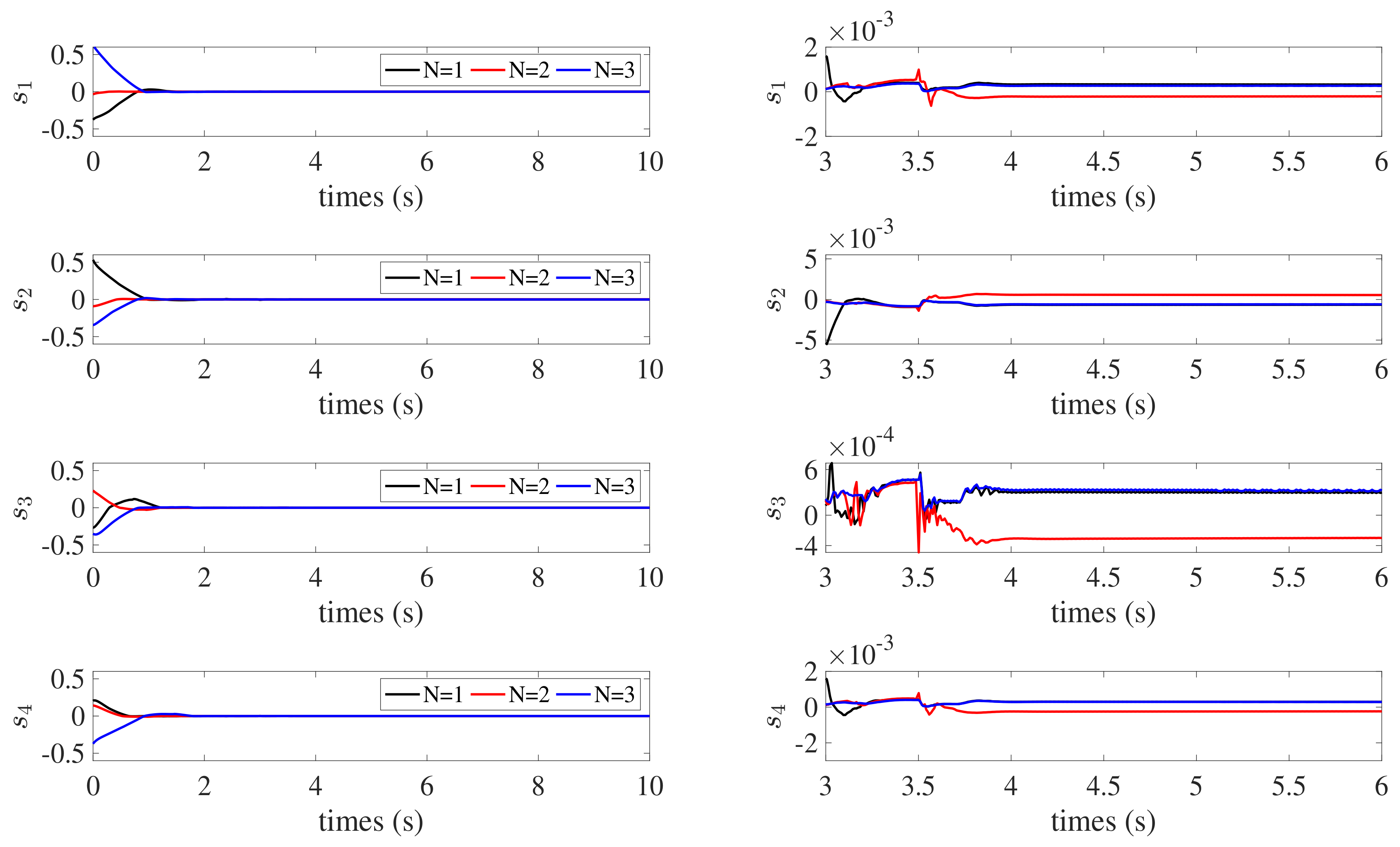
According to the simulation results, the proposed control law can successfully accomplish attitude synchronization with accuracy and stability in the presence of external disturbances and parameter uncertainties. As shown in Figure 5 and Figure 6, σ ˜ i converges to the region σ ˜ i N < 3 × 10 4 , and v ˜ i converges to the region v ˜ i N < 2 × 10 5 . s i converges to the region s i N < 6 × 10 4 , which is shown in Figure 7. In Figure 4, the attitude tracking error e 1 i converges to e 1 i N < 3 × 10 4 within 4 s. The attitude of the leader spacecraft is dynamic; therefore, the control torques continue to exist in the control process, as illustrated in Figure 8. The simulation results demonstrate the effectiveness of the fixed-time state estimator and fixed-time attitude cooperative control law designed for SSF under the directed graphs in this paper.

5. Conclusions

A distributed fixed-time estimator for SSF under a directed communication topology was investigated in this study. Based on this approach, combined with the adaptive control law, a distributed fixed-time coordinated attitude tracking control law is proposed. The control law guarantees attitude synchronization of all spacecraft in a fixed time. The settling time of the fixed-time control law is independent of the initial state; therefore, the fixed-time control law exhibits excellent control performance. The stability of the system was proven by Lyapunov stability theory, and the effectiveness of the proposed control law was proven by the simulation results. Most of the previous studies only designed fixed-time spacecraft formation attitude state estimators under an undirected communication topology. This paper proves that the designed state estimator can be applied in a directed graph so that the fixed-time algorithm and the state estimator can be combined under a directed communication topology. This can provide support for more restrictive space missions.

Author Contributions

Z.Z. is responsible for writing, mathematical derivation and simulation verification, and Y.W. is responsible for review and guidance. All authors have read and agreed to the published version of the manuscript.

Funding

This research received no external funding.

Data Availability Statement

All parameters and data required in the study have been presented in the manuscript.

Conflicts of Interest

The authors declare no conflict of interest.

References

  1. Du, H.B.; Li, S.H.; Qian, C.J. Finite-Time attitude tracking control of spacecraft with application to attitude synchronization. IEEE Trans. Autom. Control. 2011, 56, 2711–2717. [Google Scholar] [CrossRef]
  2. Wu, B.; Wang, D.; Poh, E.K. Decentralized sliding-mode control for attitude synchronization in spacecraft formation. Int. Robust Nonlinear Control. 2013, 23, 1183–1197. [Google Scholar] [CrossRef]
  3. Cai, H.; Huang, J. The leader-following attitude control of multiple rigid spacecraft systems. Automatica 2014, 50, 1109–1115. [Google Scholar] [CrossRef]
  4. Zhang, C.X.; Ahn, C.K.; Wu, J.; He, W. Online-Learning Control with Weakened Saturation Response to Attitude Tracking: A Variable Learning Intensity Approach. Aerosp. Sci. Technol. 2021, 117, 106981. [Google Scholar] [CrossRef]
  5. Cao, Y.; Ren, W. Distributed coordinated tracking with reduced interaction via a variable structure approach. IEEE Trans. Autom. Control. 2012, 57, 33–48. [Google Scholar]
  6. Zhang, Y.; Yang, Y.; Zhao, Y. Distributed finite-time tracking control for nonlinear multi-agent systems subject to external disturbances. Int. J. Control. 2013, 86, 29–40. [Google Scholar] [CrossRef]
  7. Wang, X.; Li, S.; Shi, P. Distributed finite-time containment control for double-integrator multiagent systems. IEEE Trans. Cybern. 2014, 44, 1518–1528. [Google Scholar] [CrossRef] [PubMed]
  8. Tian, B.; Yin, L.; Wang, H. Finite-time reentry attitude control based on adaptive multivariable disturbance compensation. IEEE Trans. Ind. Electron. 2015, 62, 5889–5898. [Google Scholar] [CrossRef]
  9. Polyakov, A. Nonlinear feedback design for fixed-time stabilization of Linear Control Systems. IEEE Trans. Autom. Control. 2012, 57, 2106–2110. [Google Scholar] [CrossRef]
  10. Sui, W.S.; Duan, G.R.; Hou, M.Z. Distributed fixed-time attitude synchronization control for sultiple rigid spacecraft. Int. J. Control. Autom. Syst. 2019, 17, 6. [Google Scholar] [CrossRef]
  11. Zou, A.; Li, W. Fixed-Time output-feedback consensus tracking control for second-order multiagent systems. Int. J. Robust Nonlinear Control. 2019, 29, 2. [Google Scholar] [CrossRef]
  12. Wu, Y.; Wang, Z.; Huang, Z. Distributed fault detection for nonlinear multi-agent systems under fixed-time observer. J. Frankl. Inst. 2019, 256, 13. [Google Scholar] [CrossRef]
  13. Mei, J.; Ren, W.; Ma, G.F. Distributed containment control for Lagrangian networks with parametric uncertainties under a directed graph. Automatica 2012, 48, 653–659. [Google Scholar] [CrossRef]
  14. Wang, W.; Li, C.; Sun, Y. Distributed coordinated attitude tracking control for spacecraft formation with communication delays. ISA Trans. 2018, 85, 97–106. [Google Scholar] [CrossRef] [PubMed]
  15. Zhou, Z.J. Distributed Fixed-Time Coordinated Attitude Tracking Control with a Dynamic Leader for Spacecraft Formation Flying System. Math. Probl. Eng. 2022, 2022, 3425073. [Google Scholar] [CrossRef]
  16. Chen, T.; Shan, J.; Wen, H. Distributed Adaptive Attitude Control for Networked Underactuated Flexible Spacecraft. IEEE Trans. Aerosp. Electron. Syst. 2019, 55, 215–225. [Google Scholar] [CrossRef]
  17. Zhai, D.H.; Xia, Y.Q. Adaptive control of semi-autonomous teleoperation system with asymmetric time-varying delays and input uncertainties. IEEE Trans. Cybern. 2017, 47, 3621–3633. [Google Scholar] [CrossRef] [PubMed]
  18. Godsil, C.; Royle, G. Algebraic Graph Theory; Springer: Berlin/Heidelberg, Germany, 2001. [Google Scholar]
  19. Ren, W.; Cao, Y. Distributed Coordination of Multi-Agent Networks; Springer: Berlin/Heidelberg, Germany, 2011. [Google Scholar]
  20. Qu, Z. Cooperative Control of Dynamical Systems; Springer: Berlin/Heidelberg, Germany, 2009. [Google Scholar]
  21. Roger, H.; Charles, J. Topics in Matrix Analysis; Cambridge University Press: Cambridge, UK, 1991. [Google Scholar]
  22. Zuo, Z.Y.; Lin, T. A new class of finite-time nonlinear consensus protocols for multiagent systems. Int. J. Control. 2014, 87, 363–370. [Google Scholar] [CrossRef]
  23. Peng, K.; Yang, Y. Leader-following consensus problem with a varying-velocity leader and time-varying delays. Phys. A Stat. Mech. Its Appl. 2009, 388, 193–208. [Google Scholar] [CrossRef]
  24. Zhu, Z.H.; Guo, Y. Adaptive coordinated attitude control for spacecraft formation with saturating actuators and unknown inertia. J. Frankl. Inst. 2019, 356, 1021–1037. [Google Scholar] [CrossRef]
Figure 1. Schematic diagram of the fixed-time attitude cooperative control law.
Remotesensing 14 04162 g001
Figure 2. Directed communication topology between spacecraft.
Remotesensing 14 04162 g002
Figure 3. Comparative control performance of the attitude cooperative control law without a state estimator.
Remotesensing 14 04162 g003
Figure 4. Attitude tracking error e 1 i of the follower spacecraft.
Remotesensing 14 04162 g004
Figure 5. Attitude estimation errors σ ˜ i of the follower spacecraft.
Remotesensing 14 04162 g005
Figure 6. Estimation error for the attitude derivative v ˜ i of the follower spacecraft.
Remotesensing 14 04162 g006
Figure 7. Auxiliary variable s i of the follower spacecraft.
Remotesensing 14 04162 g007
Figure 8. Control torques u i of the follower spacecraft.
Remotesensing 14 04162 g008
Table 1. Initial attitude and rigid partial inertia matrix of spacecraft.
SpacecraftInertiaInitialInitial
MatrixAttitudeDerivative
No . i J i ( kg · m 2 ) σ i ( 0 ) σ ˙ i ( 0 )
1 30 0 . 8 2 0 . 8 18 3 2 3 24 0.0462 0.0215 0.050 0 0 0
2 28 0 . 6 2 0 . 6 32 2 . 6 2 2 . 6 30 0.0542 0 . 0114 0 . 0548 0 0 0
3 36 1 4 1 26 3 . 2 4 3 . 2 28 0.0385 0 . 0484 0 . 064 0 0 0
4 32 1 . 2 2 1 . 2 30 2 . 8 2 2 . 8 34 0.0372 0.0385 0.0758 0 0 0
Publisher’s Note: MDPI stays neutral with regard to jurisdictional claims in published maps and institutional affiliations.