Article

Optomechanical Accelerometers for Geodesy

Texas A&M University, Aerospace Engineering & Physics, College Station, TX 77843, USA
*
Author to whom correspondence should be addressed.
Remote Sens. 2022, 14(17), 4389; https://doi.org/10.3390/rs14174389
Submission received: 12 July 2022 / Revised: 16 August 2022 / Accepted: 1 September 2022 / Published: 3 September 2022

Abstract

:
We present a novel optomechanical inertial sensor for low-frequency applications and corresponding acceleration measurements. This sensor has a resonant frequency of 4.715 (1) Hz, a mechanical quality factor of 4.76(3) × 105, a test mass of 2.6 g, and a projected noise floor of approximately 5 × 10⁻¹¹ ms−2/ Hz at 1 Hz. Such performance, together with its small size, low weight, reduced power consumption, and low susceptibility to environmental variables such as magnetic field or drag conditions makes it an attractive technology for future space geodesy missions. In this paper, we present an experimental demonstration of low-frequency ground seismic noise detection by direct comparison with a commercial seismometer, and data analysis algorithms for the identification, characterization, and correction of several noise sources.

1. Introduction

Satellite geodesy missions such as the Gravity Recovery and Climate Experiment (GRACE) [1] and GRACE Follow-on (GRACE-FO) [2] are equipped with low-frequency three-axis accelerometers used to detect nongravitational accelerations. These accelerations include forces such as air drag, thruster activation, and radiation pressure in the twin-satellite constellation, which are essential measurements to be removed from the missions’ gravity observations. The accelerometers deployed in GRACE and GRACE-FO are electrostatic in nature, reaching acceleration sensitivities of 1 × 10 10   ms 2 / Hz [3,4].
One major challenge posed by these accelerometers, however, is the difficulty to be tested on-ground. These sensors feature quasi-free-falling test masses with no rigid connections to their electrostatic housing. When not in orbit, the test masses cannot be electrostatically suspended and therefore cannot easily be tested. This problem can hence be avoided by suspending a test mass mechanically, such as with flexures. Optomechanical sensors, for example, can track the motion of a mechanically suspended test mass using optical readout methods. While a monolithic suspension can help improve significantly the accelerometer robustness, it imposes limitations to its performance as a trend of 1 / f 1 / 2 toward very low frequencies.
In spite of such limitations, we expect the sensitivities of these optomechanical devices to be at the levels of valuable scientific observations, while featuring a very small and lightweight footprint. In addition, their performance is independent of drag conditions (and thus drag-free or drag compensation controls are not required), insensitive to magnetic fields, and easy to be thermally controlled due to their small size and weight. To this end, we propose the use of an optomechanical accelerometer for use in future geodesy missions, either by replacing current accelerometers or complementing future baseline instruments as risk-reduction devices, such as gravitational reference sensors [5,6] or quantum gravimeters and gradiometers [7,8,9]. In addition, they could be applicable for interplanetary missions studying the gravity fields around other bodies in our solar system [10]. Finally, they are suitable for ground-based and planetary seismology and geodesy applications [11,12], due to the fact that they can be readily operated under normal gravitational potentials such as Earth’s gravity.
Over the past 10 years, optomechanical sensors have been used for many different high-precision sensing applications. Force sensitivities on the order of 10 fN at room temperature have been demonstrated using a 10 kHz mechanical resonator with a cavity readout [13]. Optomechanical magnetometers have realized sensitivities better than 1 n T / Hz over a GHz bandwidth using the mechanical modes of barium titanium silicate microspheres [14]. Furthermore, nano-optomechanical displacement sensors with operational bandwidths of several MHz have been developed with noise floors on the order of 10 f m / Hz [15]. Yet other applications include atomic force microscopy and acoustic sensing. Finally, optomechanical sensors have been used for accelerometry, demonstrating an acceleration noise of 100 n g over a 10 kHz bandwidth [16].
However, it is worth mentioning that all the above examples use mechanical resonators with eigenfrequencies in the kHz or higher. While low-frequency accelerometers have been developed and tested for various applications, most of them are read out electrostatically [10]. Hence, optomechanical devices have not been investigated as closely, due to the larger physical dimensions, higher cost, and poorer sensitivities to high-frequency signals. Yet many fields such as seismology, geophysics, geodesy, hydrology, and more require the observation of acceleration signals below 1 Hz. Previous work on a low-frequency optomechanical accelerometer demonstrated high mechanical quality factors on the order of 1 × 10⁵ with a 2 g, 3.7 Hz test mass, corresponding to thermal acceleration sensitivity limits on the order of 1 × 10 10   ms 2 / Hz [17]. The drawback of this device was the inability to integrate the optical readout onto the wafer the resonator was etched from. In this paper, we present our low-frequency optomechanical accelerometer, consisting of a 5 Hz mechanical resonator whose displacement from equilibrium is tracked with laser interferometry. This resonator is designed to be easily integrated with the optical readout, which is advantageous for maintaining a compact form. We describe the characterization process that suggests this resonator is a promising candidate for a novel accelerometer for space geodesy, as well as ground-based planetary and navigation applications. Using a ringdown measurement, we find the mechanical quality factor of this device to be 4.76(3) × 105, corresponding to a thermal acceleration noise on the order of 5 × 10 11   m s 2 / f below resonance. Furthermore, we compare acceleration measurements from our resonator to those from a commercial seismometer to demonstrate the resonator’s ability to detect seismic motion down to 1 mHz.

2. Methods

2.1. Optomechanical Accelerometers

Our optomechanical accelerometer is composed of two main components: the mechanical resonator and the laser interferometric readout. In this section, we discuss the design of both parts and present characterization measurements which can be used to project the acceleration noise floor of our device.

2.1.1. Resonator—Design and Characterization

We designed a resonator intended to be used for 1D acceleration measurements, though a triaxial device would be a straightforward extension of the topology presented here. This resonator was laser-assisted dry-etched from a single monolithic fused silica wafer and was 90   m m × 80   m m × 6.6   m m in volume with a total mass of 58.2   g . Our accelerometer had a smaller form and lighter weight than the GRACE-FO accelerometer, representing a major advantage for satellite missions. An image of our resonator is shown in Figure 1. Our design consisted of a 2.6   g parallelogram test mass supported by two 100 μ m thick leaf-spring flexures.
A finite element analysis (FEA) simulation performed in COMSOL predicted a 5.5 Hz resonant frequency, which made our resonator suitable for measuring noninertial disturbances below 1 Hz. At frequencies below resonance, the test mass response x to an external acceleration a was approximately given by:
x a ω 0 2
where ω 0 is the angular resonant frequency. There is a trade-off between the required displacement sensitivity, how low the resonance can be in a practical resonator, and its final dimensions. Therefore, a resonance on the order of 1 Hz allows this low-frequency noise to couple into the test mass motion better than a high resonance device, which in turn relaxes the required test mass readout precision. Conversely, a lower resonance device requires a larger resonator, which quickly becomes more difficult to work due to the low stiffness.
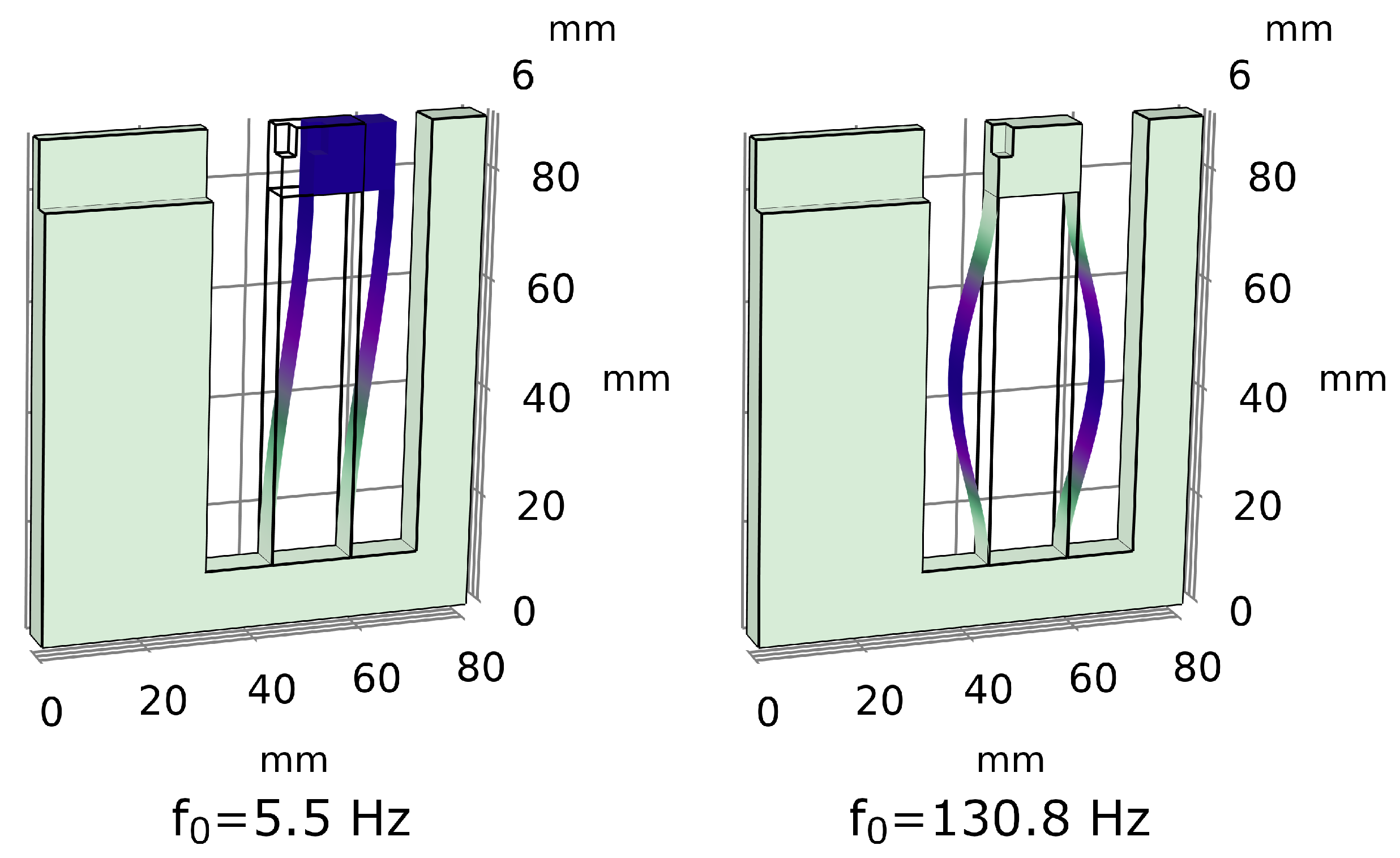
Furthermore, our simulations predicted that all higher-order modes had frequencies above 130 Hz, significantly higher than the lowest resonance by over an order of magnitude. This was desired for mitigating the cross talk between modes that appeared in our measurements, which in turn reduced the noise in our data. Figure 2 shows the first two modes of this resonator: the first being the translational mode of the test mass and the second being a violin mode of the flexures with a significantly higher frequency.
The acceleration experienced by the resonator was recovered by applying a transfer function, which was defined by the resonance and quality factor, to the test mass’s displacement data. This transfer function was given by [17]:
x ˜ ( ω ) a ˜ ( ω ) = 1 ω 0 2 ω 2 + i ω 0 ω / Q
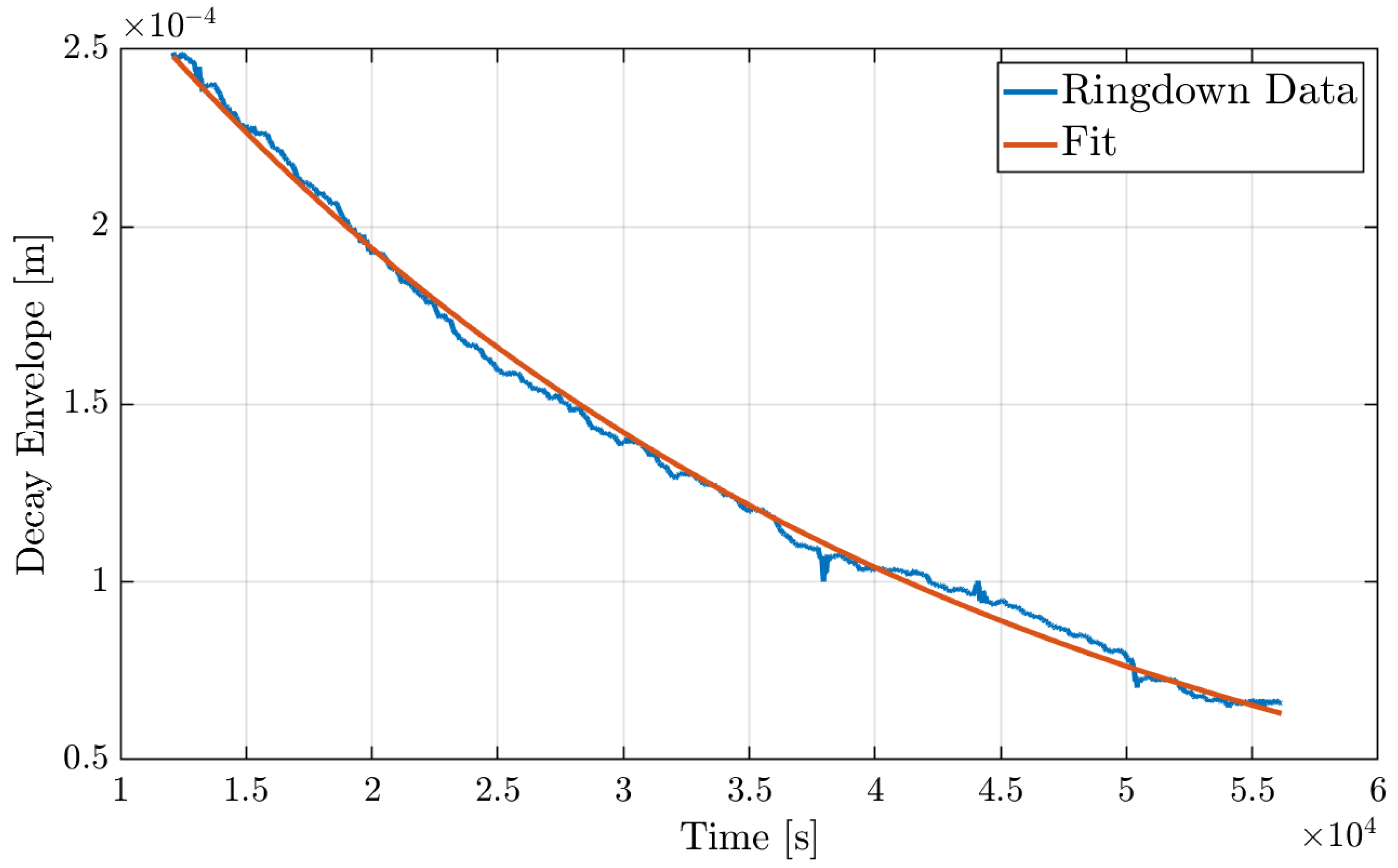
where x ˜ ( ω ) is the test mass motion, a ˜ ( ω ) is the acceleration coupling into the resonator, ω 0 is the resonant frequency, and Q is the mechanical quality factor. Note that when ω < < ω 0 , Equation (2) simplifies to Equation (1). To characterize the acceleration sensing capabilities of our resonator, we experimentally determined these parameters using a ringdown test where we deliberately excited the test mass motion and tracked its oscillations. In the absence of other perturbations, the oscillation amplitude exponentially decayed, allowing for an easy calculation of Q. Figure 3 depicts the decay envelope of our ringdown measurement, which was performed over 14 h at a vacuum pressure of 10 μTorr. From this measurement, we found a Q-factor of 4.76(3) × 105 and an m Q -product larger than 1250 k g . Furthermore, taking the fast Fourier transform (FFT) of the raw data yielded a resonant frequency of f 0 = 4.715 (1) Hz, in good agreement with our simulated value of 5.5 Hz. The transfer function in Equation (2) could then be evaluated using our experimentally determined parameters. We applied this transfer function to the displacement measurements in the frequency domain to convert the signal to acceleration noise.

2.1.2. Laser Interferometer—Design and Characterization

In order to measure the local acceleration noise, we must measure the displacement of the test mass from its equilibrium. For this, we constructed a heterodyne displacement interferometer with a differential phase readout. Cutouts on the test mass and the u-shaped frame of our resonator, shown in Figure 1, allowed for an easy implementation of mirrors that completed this laser interferometer. The optical methods and noise rejection schemes used for this readout are discussed in greater detail in [18], though an overview of this optical readout is provided in this section. Figure 4 contains a diagram of our laser interferometer. A fiber-coupled 1064.181   n m beam was split and frequency-shifted by two acoustic-optical modulators (AOMs) to create a 5 MHz heterodyne frequency. The frequency shifted beams were then injected into a series of prisms that created two distinct Mach–Zehnder type interferometers: one that tracked the test mass motion and one that acted as a reference.
The measurement interferometer sent one beam to a mirror on the test mass, M M , where the displacement information was imprinted on the phase of the reflected beam. Similarly, the reference interferometer reflected one beam off a stationary mirror, M R . The second beams for both interferometers reflected off the same common mirror, M. Common mode noise sources, such as temperature fluctuations in the prisms, coherently affect both interferometers. Therefore, a differential phase measurement rejected some environmental noise and allowed for high-sensitivity displacement sensing.
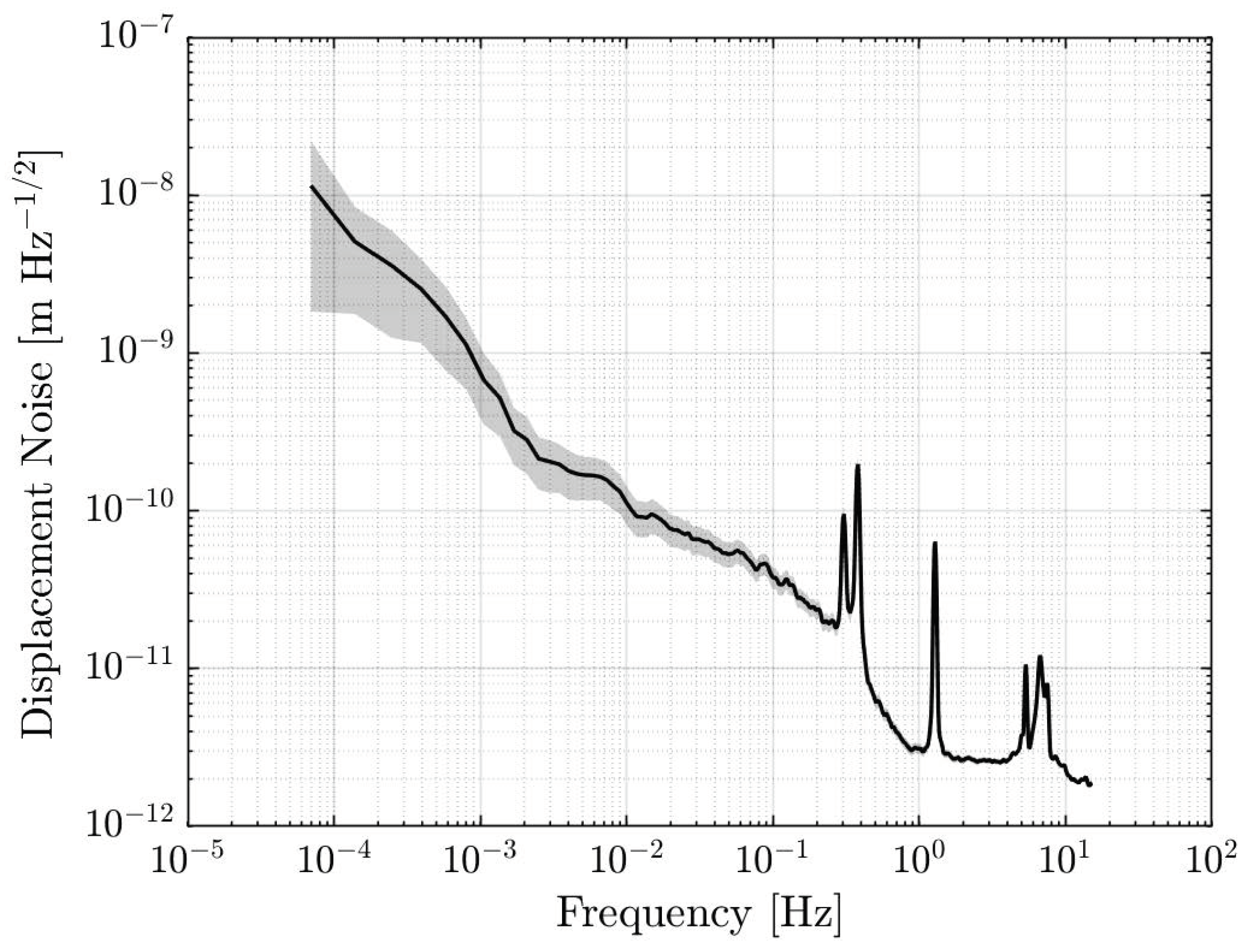
Furthermore, the laser added noise to our data in the form of laser frequency noise. To combat this, we also introduced a delay-line interferometer to the setup. This interferometer allowed us to make independent measurements of the frequency noise by interfering one beam from the laser with a delayed copy of itself. By creating a path-length difference of 2 m in the delay-line interferometer arms, laser frequency fluctuations became the dominant noise source in this fiber interferometer, although its signal-to-noise ratio (SNR) decreased toward lower frequencies due to fiber noise. With this measurement, we were able to remove the laser frequency noise from the resonator data in postprocessing. However, for example, in future space geodesy missions, a frequency-stabilized laser source would be available, offering a much better stability than what can be achieved through postcorrection and therefore eliminating the need for a delay-line interferometer. The readout displacement noise, taken with a stationary mirror in place of the test mass mirror, is shown in Figure 5. We find that this interferometer can measure displacement data with a sensitivity of 3 × 10⁻¹² m/ Hz at 1 Hz and 7 × 10⁻¹⁰/ Hz at 1 mHz. The peaks near 0.4 Hz and 1 Hz are caused by the mechanical resonances of a vibration isolation platform the interferometer was placed on while testing.

2.2. Accelerometer Noise Floor

The acceleration sensitivity of our optomechanical accelerometer was anticipated to be limited by both the thermal noise of the resonator and the displacement noise from the readout interferometer. In this section, we estimated both contributions in order to calculate the acceleration noise floor.
Thermal noise, which represents the ultimate acceleration sensitivity that can be achieved with our resonator, is caused by gas damping and internal loss mechanisms within the fused silica. These loss mechanisms include bulk losses, surface losses, and thermoelastic losses. The thermal acceleration noise can be derived from theory starting from the equation of motion for a resonator, given by [17,19]:
m a = m x ¨ + m Γ x ˙ + m ω 0 2 ( 1 + i ϕ ( ω ) ) x
where m is the test mass, Γ is the gas damping rate, and ϕ ( ω ) is the internal loss coefficient of our fused silica oscillator. Converting to the frequency-domain and applying the fluctuation–dissipation theorem [19], we find that the thermal acceleration noise is given by:
a ˜ th 2 ( ω ) = 4 k B T m ω ( ω Γ + ω 0 2 ϕ ( ω ) )
where T is the temperature of the test mass and k B is Boltzmann’s constant. In general, both gas damping and internal losses contribute to the thermal noise. However, because our testing environment could reach μTorr pressures, we operated under the assumption that gas damping was negligible in comparison to internal losses. Previous work on a similar resonator estimated that a vacuum pressure of 10 μTorr would be sufficient for making gas damping negligible compared to other mechanical losses, which is achieved both in laboratory environments, portable vacuum enclosures, and certainly space geodesy missions. Therefore, for the remainder of the paper, we let Γ = 0 .
We can calculate ϕ ( ω ) using known equations for the different loss mechanisms [20,21,22,23], but this is not ideal for our purposes. The mechanical losses of fused silica have been studied intensively by the gravitational wave community for use in low-thermal noise test mass suspensions. The models developed by these investigations are useful for optimizing a fused silica sensor’s topology, but the only information we can experimentally obtain for ϕ ( ω ) is the Q-factor. Therefore, we want an equation for the thermal noise in terms of Q rather than ϕ ( ω ) . For this, we assume that the internal losses are constant in the bandwidth of interest and are given by:
ϕ ( ω ) = 1 Q
Using these assumptions, we simplify Equation (4) to:
a ˜ th 2 ( ω ) = 4 k B T ω 0 2 m Q ω
This is the final equation we used to calculate the thermal acceleration noise. Note that larger Q-factors lead to lower thermal noise, highlighting the importance of fused silica as a material of choice. Fused silica is known to have very low internal losses at room temperature, with Q-factors well above 1 × 10⁶ for high-frequency resonators [24,25,26,27,28] and above 1 × 10⁵ for low-frequency devices [17]. Research into the material properties of fused silica at cryogenic temperatures has shown that the mechanical losses ϕ of this material increases substantially as temperature decreases [29]. At 30 K , these losses can increase by as much as four orders of magnitude, which would in turn increase the thermal acceleration noise of our optomechanical accelerometer by a factor of 100. Moreover, this work suggested a fused silica resonator could be operated at temperatures as low as 225 K with minimal quality factor degradation of at most a few percent. Hence, we adopted 225 K as the minimum operating temperature of our accelerometer, which was not anticipated to impede our device’s performance in the context of space geodesy, as such systems typically operate near room temperature.
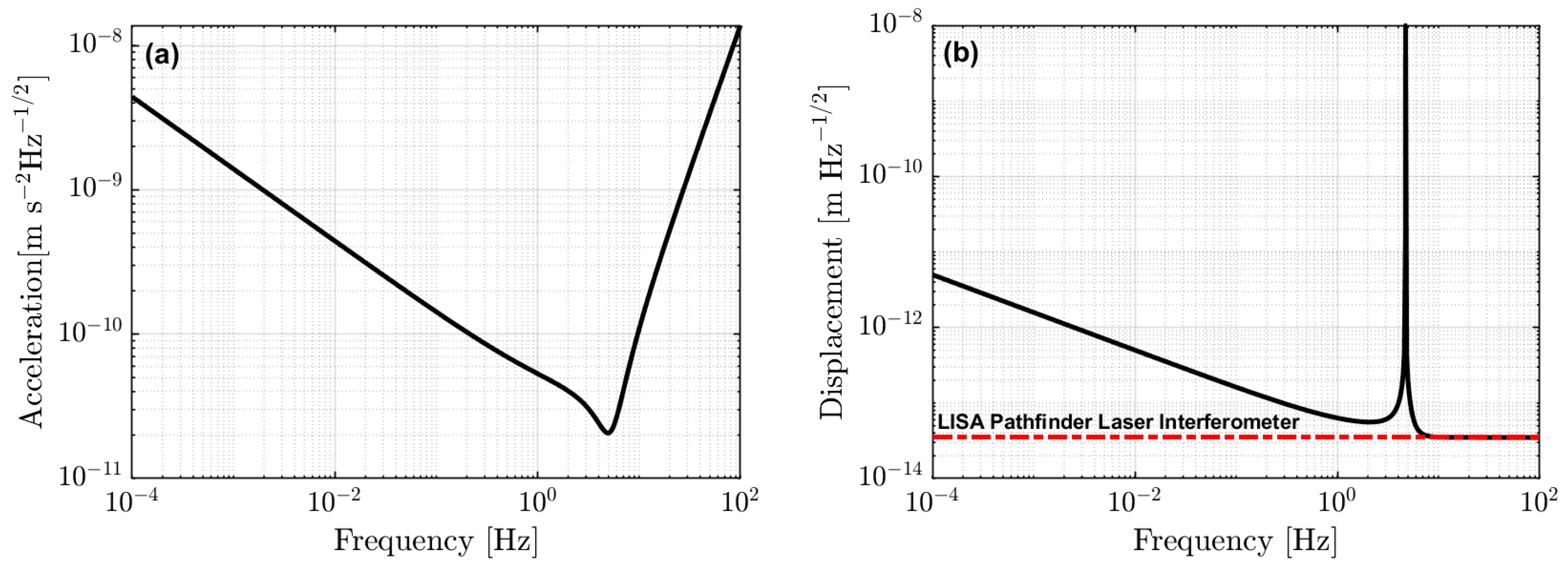
In addition to thermal motion, displacement readout noise from the laser interferometer contributed significantly to the acceleration noise floor of our optomechanical accelerometer. For this section, we note that the Laser Interferometer Space Antenna (LISA) Pathfinder mission has demonstrated an optical readout with a sensitivity reaching 35 f m / Hz [30], representing an excellent sensitivity level that can be used to model our own projected noise floor. To convert this displacement noise to acceleration, we simply applied the transfer function in Equation (2). This readout noise was assumed to be incoherent with the thermal motion of the resonator, so the two noises added in quadrature:
a ˜ floor 2 ( ω ) = a ˜ th 2 ( ω ) + | a ˜ ( ω ) x ˜ ( ω ) | 2 x ˜ int 2 ( ω )
Equation (7) is plotted in Figure 6a, where we observe the acceleration sensitivity is anticipated to be 5 × 10 11   ms 2 / Hz at 1 Hz and increases towards low frequencies as f 1 / 2 . Above resonance, the noise floor increases rapidly, dominated by readout noise, while below resonance the thermal motion is sufficiently low that the noise floor is 1 × 10 9   ms 2 / Hz at 1 mHz.

3. Results

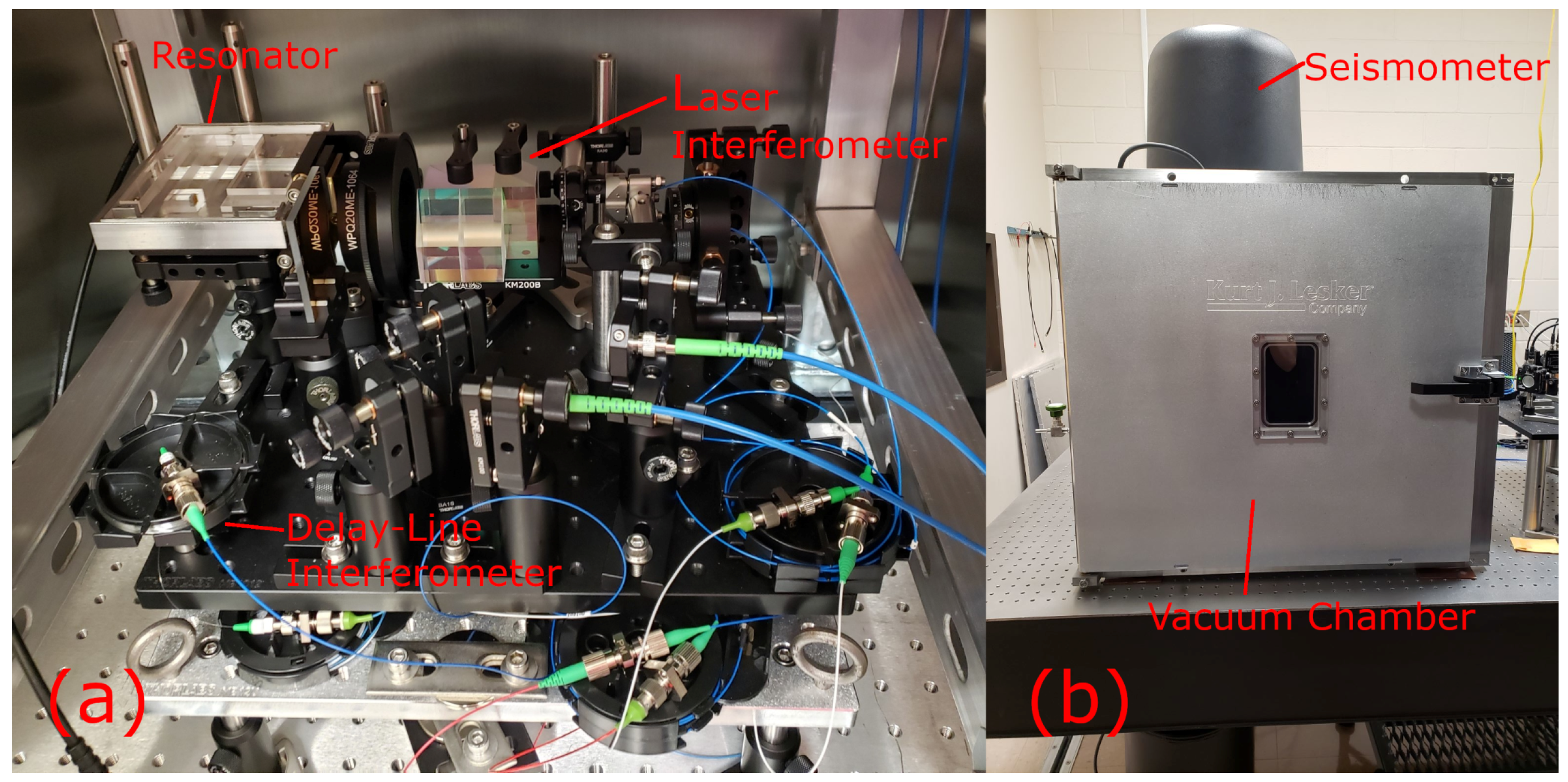
To demonstrate the acceleration sensing capabilities of our device, we took simultaneous measurements with the optomechanical accelerometer and a Nanometrics Trillium Horizon 120-2 (T120H) seismometer [31]. The T120H seismometer was placed on top of the vacuum chamber that housed the resonator to ensure seismic noise coupled into both accelerometers coherently. Moreover, the axis of motion for the resonator was set up to coincide with the x-axis of the seismometer, allowing for an easy comparison of the two sensors. Photos of this setup are shown in Figure 7. In this section, we present preliminary measurements taken with our optomechanical accelerometer and describe the correction methods we used to remove various noise sources.

3.1. Measuring Seismic Noise

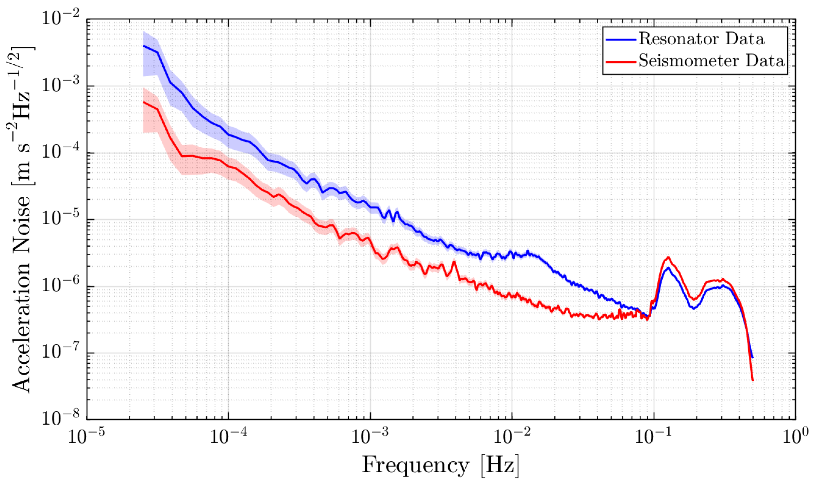
Data were taken for 60 h allowing us to observe frequencies as low as 4.6 μHz. The acceleration noise observed by both devices is shown in Figure 8, where we note the agreement in the microseismic band between 100 mHz and 500 mHz. The seismometer detected less noise at frequencies below this bandwidth, indicating that our optomechanical accelerometer was limited by environmental noise below 100 mHz. Even though our optomechanical accelerometer’s observed noise is significantly higher than the measured optical readout noise in Figure 5, the laser path length difference between the measurement and reference interferometers when the resonator is incorporated in the setup is greater than 1 cm. This in turn enlarges the laser frequency noise in comparison to what was observed in the interferometer stability test.

3.2. Data Post-Correction

The data taken with our optomechanical accelerometer presented in Section 3.1 were initially unable to observe the same acceleration noise as our T120H seismometer below 100 mHz due to a combination of signals originating from the environment and the optical readout. However, with careful environmental monitoring, some of this noise could be removed in postcorrection. In this section we discuss the different noise removal methods we utilized in our data to achieve a better acceleration sensitivity, and correspondingly a better agreement with the commercial seismometer.

3.2.1. Time-Domain Linear Regression

A portion of the environmental noise in our data could be removed by performing linear fittings to different sets of environmental data taken at the same time as the acceleration measurement. In addition to the previously discussed delay-line interferometer, this environmental data included the room temperature, vacuum chamber temperature, vacuum pressure, and the heterodyne signal amplitudes of the measurement, reference, and delay-line interferometers. Furthermore, we retrieved data on the ambient weather conditions from Texas A&M University’s Research Farm [32], as the changing barometric pressure can induce tilting in our optical bench which causes a projection of the local gravity into the resonator’s axis of motion.
For frequencies below 100 μHz, we found that the barometric pressure dominated the resonator’s acceleration noise, with a coupling coefficient of 29.24   m m   s 2   Bar 1 found by linear regression in the time domain. To isolate the frequency band where the pressure noise dominated, this linear regression was performed on bandpass-filtered data. While effective, the efficacy of this postcorrection was limited by the data acquisition of the weather station at Texas A&M’s Research Farm, which reported hourly averages. The ultralow Nyquist frequency of 139 μHz restricted our ability to correct our data for barometric pressure fluctuations above that frequency. As part of our ongoing efforts to develop this technology, we will include in-house measurements of the ambient laboratory air pressure taken with a commercial barometer sampled at a much higher rate to avoid this problem.
The acceleration noise caused by laser frequency noise was found in a similar way. Laser frequency fluctuations appeared in our resonator data as a bump around 12 mHz, which can be observed in Figure 8. By applying a bandpass filter with corner frequencies of 5 mHz and 40 mHz to the resonator and delay-line interferometer data, we found a coupling coefficient of 1.1421   μ m   s 2   rad 1 . This coupling coefficient informed us on how stable a laser would need to be in order for our resonator to be thermally limited. The phase of our delay-line interferometer, ϕ delay , was proportional to our laser source’s frequency noise, ν laser , by [18]:
ϕ delay = 2 π Δ L c ν laser
where c is the speed of light and Δ L is the path length difference in the delay-line interferometer, which was 2 m in our case. This suggested that the coupling factor between our resonator’s acceleration, a, and the laser frequency noise ν laser was 4.709 × 10 14   m s 2 Hz−1. Using our projected thermal acceleration noise shown in Figure 6, we anticipated a laser frequency stability of 1.06 kHz / f would be required for observing the thermal motion of our resonator. This stability is very achievable, and the frequency stability of the laser onboard GRACE-FO is much better than this requirement [33].

3.2.2. Transfer Function

The linear regression method of noise subtraction that we used for the barometric pressure and laser frequency corrections assumed that the phase and amplitude of their respective coupling coefficients were uniform over the bandwidths we were correcting. However, noise generally does not couple into a given system uniformly in frequency; both the amplitude and phase of the coupling factor can be frequency-dependent. The temperature inside our vacuum chamber for example was a significant source of noise in our experiment, but it did not couple uniformly in frequency. Because of this, we had to use a different approach to remove the temperature effects from our data. We corrected for the vacuum chamber temperature by calculating a transfer function, H T a ( ω ) , between the temperature and acceleration data [34]. This transfer function is typically estimated by taking the ratio of the cross-power spectral density (CPSD) of the acceleration and temperature data, S T a ( ω ) , and the power spectral density (PSD) of the acceleration, S a a ( ω ) [35]:
H T a ( ω ) = S T a ( ω ) S a a ( ω )
For this spectral analysis, we used a Nuttall window function and 1.98 × 10⁵ samples. The number of averages increased with frequency. The lowest frequency bin, 5 μHz, had only one average, which increased to over 1100 averages at 0.5 Hz. At 230 μHz, there were 10 averages, and so we adopted this frequency as the approximate cutoff below which the spectral analysis had too few averages to be reliable. This analysis was performed with LTPDA, an open-source MATLAB toolbox for data analysis and signal processing developed and distributed by the LISA Pathfinder community [36].
The amplitude of the transfer function between the vacuum chamber temperature and the resonator’s acceleration after removing laser frequency and barometric pressure noise is shown in Figure 9. We observe a frequency-dependent transfer function amplitude ranging from 2 × 10⁻³ ms−2K−1 to 1 × 10⁻² ms−2K−1. Similar to laser frequency noise, the transfer function presented in Figure 9 can be used to estimate the temperature stability required for the resonator to be limited by thermal motion. At 10 mHz, the amplitude of this transfer function is on the order of 10 mms−2K−1, while the thermal acceleration noise at this frequency is approximately 4 × 10 10   m / s 2 / Hz . This suggests that a thermally limited acceleration measurement would require an environmental temperature stability of 4 × 10 8   K / Hz . This requirement being very improbable to achieve, we instead investigated the precise mechanism through which temperature coupled into our setup and reduced it to relax the temperature stability we needed to reach.
The typical transfer function one might expect for temperature coupling is one that resembles a low-pass filter [34], which was not fully observed in our setup. This behavior could be due to the fact that temperature was a ubiquitous effect, present everywhere in the setup. The complicated transfer function could be composed of several thermal effects occurring simultaneously in different parts of the experiment. The exact mechanism causing temperature fluctuations to couple into our setup in this manner is currently under investigation.
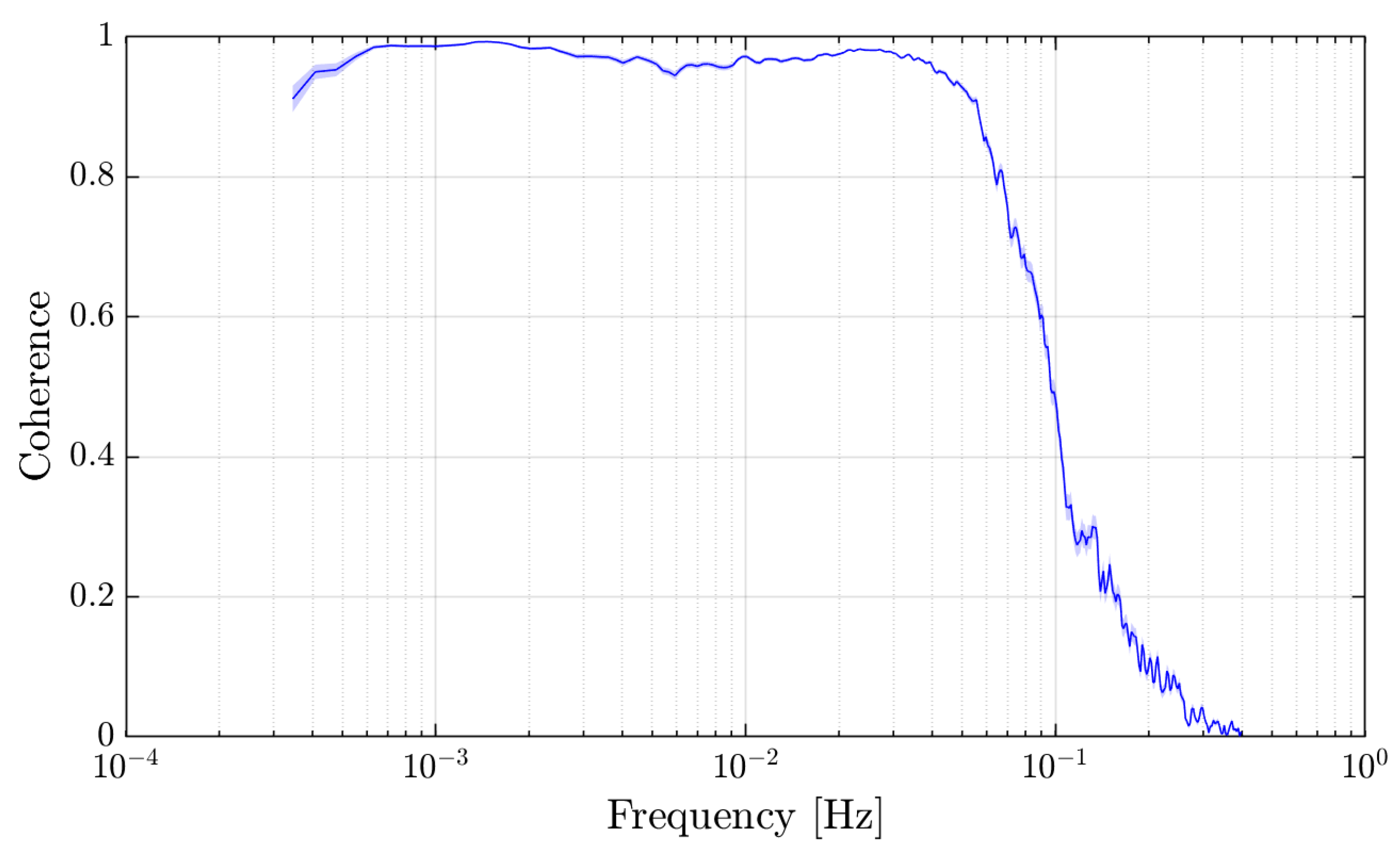
We also calculated the uncertainty in the transfer function, which depends on the transfer function amplitude, the coherence between vacuum temperature and acceleration C T a ( ω ) , and the number of averages in each frequency bin [35]. In bins where either the coherence between the two time series was poor or the number of averages was low, the variance in the transfer function was large. The coherence, shown in Figure 10, was estimated by taking the ratio of the magnitude of the cross-spectral density, | S T a ( ω ) | 2 , and the product of the power spectral densities S a a ( ω ) and S T T ( ω ) [35]:
C T a ( ω ) = | S T a ( ω ) | 2 S a a ( ω ) S T T ( ω )
The coherence between the vacuum chamber temperature and the acceleration data was larger than 0.8 between 300 μHz and 60 mHz, indicating that temperature fluctuations were a dominant noise source in this frequency band. Above 60 mHz there was a sharp decrease in the coherence, explaining the corresponding decrease in transfer function amplitude and the increase in the transfer function uncertainty.
The temperature-induced acceleration noise was calculated by taking the FFT of the temperature data, applying the transfer function, and then taking the inverse FFT to return to the time domain. The inverse transform step of this process, while not strictly necessary if one wants frequency-domain results [35], is useful for visualizing the data and identifying the next limiting noise source.
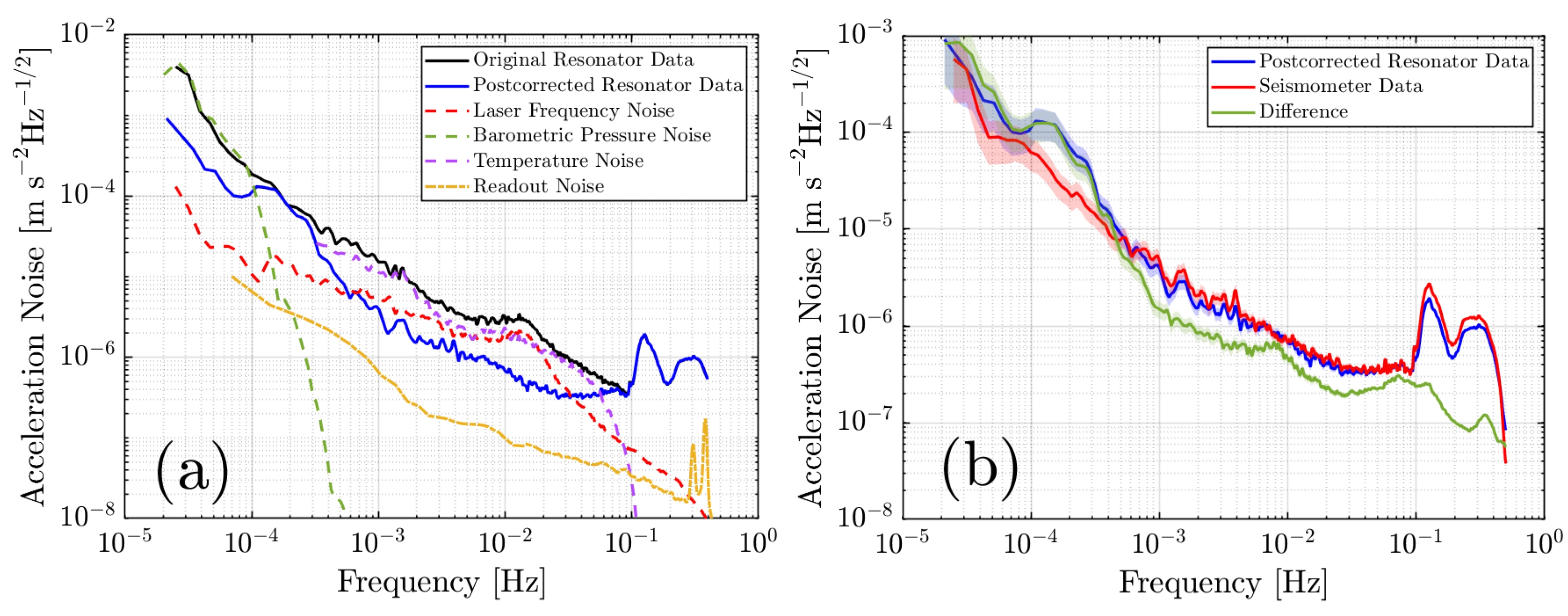
The noise breakdown for this measurement is shown in Figure 11a as well as the residual after removing the laser frequency, pressure, and temperature noise. This postcorrection is compared to the measured interferometric readout noise, from which we see that the resonator’s acceleration data are above the acceleration noise of the interferometer. This suggests that the noise we are observing is a real signal with seismic or environmental origins. Figure 11b also shows the difference between our optomechanical accelerometer data and the seismometer data. We observe that this difference is larger than the readout-induced acceleration noise, suggesting that the residual is limited by noise not originating from the optical readout. Our data do not show any more significant coherences between our acceleration and environmental monitoring. As such, we consider the possibility that the residual noise in our accelerometer data was, at least partially, introduced through postcorrection. For example, if the self-noise of our temperature sensors was on the order of 100 μK/ Hz at 10 mHz, that self-noise would be added to our acceleration measurements during postcorrection at a level of approximately 2 × 10⁻⁷ ms−2/ Hz , ultimately restricting our final sensitivity. This highlights the importance of investigating and characterizing these noise sources, as reducing their physical coupling into the experiment offers better results than decohering our data in postcorrections.
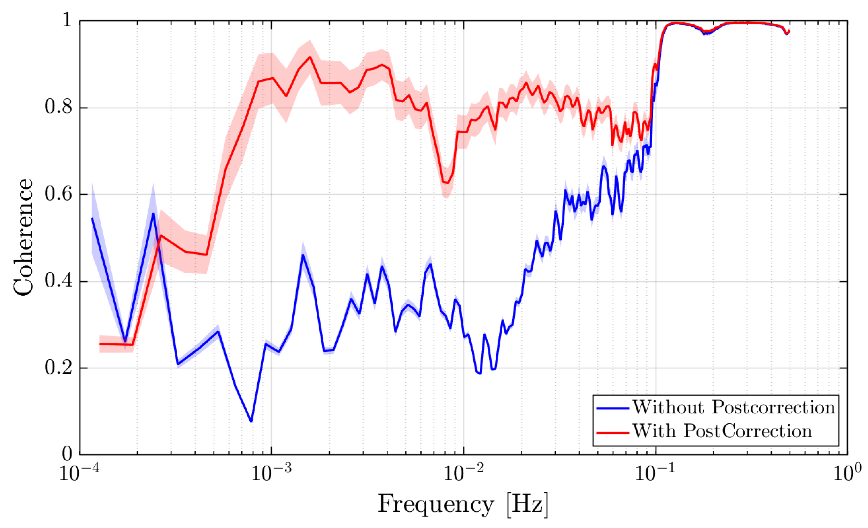
Furthermore, we find that after removing the temperature and barometric pressure fluctuations, the good agreement between our resonator and seismometer data extends down to 1 mHz, which can be visualized in frequency-space in Figure 11a and in the coherence between the two data sets in Figure 12. The bump in the postcorrected resonator data between 100 μHz and 400 μHz is likely residual barometric pressure noise that could not be removed due to the low Nyquist frequency of the pressure measurement. Moreover, we can visually compare the data from both accelerometers in the time domain to demonstrate the agreement between the sensors. In Figure 13, we plotted a 1000 s segment of both data streams and in doing so, we observed excellent agreement in both the magnitude and phase of the two devices. These comparisons validated our resonator’s ability to detect seismic noise above 1 mHz.

4. Discussion

4.1. Comparative Technology Assessment

In Section 2.2, we calculated the noise floor of our optomechanical accelerometer using estimates of the optical readout noise and the thermal motion associated with our experimentally measured Q-factor. This noise floor can be compared to existing technologies to assess the viability of our accelerometer for different applications. In Figure 14, we plotted our estimated noise floor against the GRACE [3] and GRACE-FO [4] accelerometers, as well as several ground-based seismometers including the Geotech S-13, the Nanometrics Trillium 360, and the Nanometrics Trillium 120, which is the one we utilized in our laboratory for the comparison measurements presented in Section 3.1 [37]. We observe that our accelerometer is anticipated to have a competitive, if not lower, acceleration noise than the ground-seismometers, suggesting that our device will be useful for seismometry and ground-based geodesy studies. Moreover, our accelerometer has a mass of 58.2   g , and we anticipate the realization of a highly compact and lightweight system compared to existing systems. Because of this, our optomechanical accelerometer is smaller, more portable, and better-suited for field work than these commercial technologies.
When compared to the GRACE and GRACE-FO accelerometers, our optomechanical accelerometer is competitive at higher-frequencies around 1 Hz but is expected to be noisier at lower-frequencies. However, current mass change measurements taken by satellite gravity recovery missions are limited primarily by temporal aliasing errors, not accelerometer noise [38]. Hence, despite this slightly higher noise floor at low frequencies, we expect our optomechanical accelerometers to be able to provide meaningful data for science observations. Rather, with the advantages exhibited by our optomechanical accelerometer, including a lower weight, more compact form, and the ability to be tested on-ground, our accelerometer is still valuable for satellite geodesy missions.

4.2. Planned Developments

In the measurements presented in this article, we encountered several noise sources, such as instabilities in the laser frequency and the optical readout, limiting our ability to detect low-frequency signals. Future measurements will be conducted with a frequency-stabilized laser and a compact quasi-monolithic interferometer to improve our sensor’s low-frequency sensitivity. This interferometer operates on the same principles as our current readout. It consists of prisms and beamsplitters bonded together and small enough that they can be integrated onto the wafer of our resonator, miniaturizing our current experimental setup while offering better mechanical stability. A photo of this interferometer is shown in Figure 15a.
Other improvements that can be made to reduce the measurement noise include thermally isolating the system to dampen temperature fluctuations as well as investigating noise due to tilt-to-length coupling and nonlinear optical path length differences.
Furthermore, we will experimentally measure the thermal noise floor of our accelerometer by performing a Huddle test. The test consists of placing two identical resonators close to each other. The seismic noise would couple into both devices coherently. After removing that correlated seismic noise, the remaining noise will be the uncorrelated noise originated from the resonators themselves.
These developments and a better understanding of low-frequency environmental noise sources will allow for other tests to characterize our acceleration sensing capabilities, e.g., to monitor the lunar and solar tidal acceleration changes.
Finally, there are several extensions of the work presented in this manuscript that would make this optomechanical accelerometer technology ready for use onboard a space geodesy satellite. Specifically, we are currently developing appropriate mounts and launch-lock mechanisms for the accelerometer that facilitate its deployment and protect the dynamic test mass during installation and launch. This cage should include a method of securing the test mass and flexures to avoid damage while not in use, such as during launch when significantly higher accelerations and shock are expected in contrast to science operation. To this end, the higher-order violin modes of the flexures in our accelerometer should be investigated in greater depth to ensure compatibility with the vibrational loads present during launch.
Moreover, a triaxial optomechanical accelerometer could be constructed from a series of resonators operating along different axes, which is required for observing all noninertial perturbations while in orbit. A concept design of such a sensor is depicted in Figure 15b, which has a volume of 110   m m × 110   m m × 22   m m and a mass of 0.282   k g , not including the masses of the optical readout, which should be low overall as each quasi-monolithic interferometer assembly weighs only 4.5   g . This design is a quasi-monolithic assembly of two layers of fused silica resonators that are separated by spacers. The top layer holds two orthogonal resonators identical to the one presented in Section 2.1.1 operating along the x and y axes. Because these resonators share the same topology as the one presented in this paper, they will have the same noise floors shown in Figure 6. Furthermore, on the top layer is a cutout that houses the optical readouts for all three axes. An interferometer reaches the test mass of the bottom layer through a hole in the top layer covered by a pentaprism.
The bottom layer contains a resonator that measures out-of-plane accelerations along the z-axis. However, due to limitations in fabrication, a different topology is required for measuring the out-of-plane motion. To this end, we have developed a preliminary design for the bottom layer resonator, which consists of a 12 g rectangular prism test mass supported by flexures on four sides. These flexures have cross sections of 8   m m × 0.1   m m and are oriented such that the test mass oscillates along the z-axis. Tuning the lengths of the flexures as well as the test mass allows for a natural frequency less than 10 Hz, which improves the resonator’s low-frequency sensing capabilities. Like the resonator presented in Section 2.1.1, we require all higher order modes to have resonances larger than the natural mode by an order of magnitude. In the topology we have chosen for the bottom layer resonator, however, tip-and-tilt modes can have a low enough frequency to allow cross talk between the modes of the resonator.
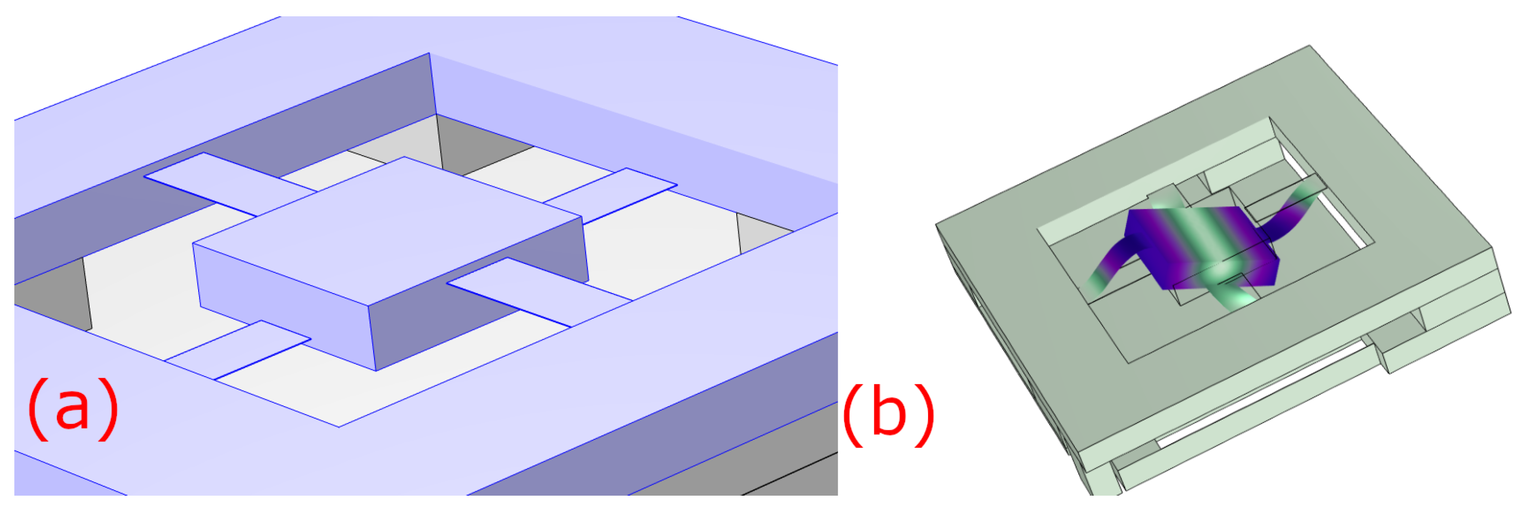
Figure 16a visualizes this tip-and-tilt mode. To combat this, we offset the flexure heights relative to the bottom of the wafer. Two flexures are 1 m m above the bottom of the wafer and the other two are 1 m m below the top of the wafer. Having the test mass and flexures connected at multiple points along the z-axis increases the frequency of this tip-tilt mode to above the 10× threshold. Figure 16b depicts a close-up of the test mass and flexures to show this offset.
With the aim of developing a triaxial accelerometer with equal noise floors along all three axes, an optimization of the bottom layer resonator must be performed to ensure it has comparable noise to the top layer resonators. This optimization includes adjusting the test mass and cross section to lower its resonance and reduce its thermal motion while keeping the stress in the flexures within a safe operating range.

5. Conclusions

In this paper, we demonstrated that a compact and lightweight optomechanical accelerometer etched from a monolithic wafer of fused silica with dimensions of 90   m m × 80   m m × 6.6   m m could detect seismic noise above 1 mHz in good agreement with commercial seismometer technologies. This device had a test mass that was suspended mechanically by thin flexures, allowing it to be tested on the ground where some electrostatic devices cannot. As such, we proposed the use of this technology onboard future space geodesy missions, as well as in ground-based planetary and geodesy applications, for measuring noninertial disturbances.
Although a direct measurement of the accelerometer’s noise floor was not possible due to our testing environment being flooded with signals, there is presently no evidence of noise sources that would prevent us from observing the self-noise of our accelerometer with a sufficiently quiet test bed. The anticipated thermal acceleration noise was approximately 5 × 10⁻¹¹ ms−2/ Hz at 1 Hz, making this technology competitive with the accelerometers that have flown on space geodesy missions such as GRACE and GRACE-FO. As such, our optomechanical accelerometer is expected to be suitable for satellite geodesy missions, among other applications.
The resonator’s displacement was measured optically with a heterodyne interferometer and a 1064 n m laser that was not frequency-stabilized. Below 100 mHz, the acceleration data obtained by our resonator were dominated by laser frequency noise as well as temperature and pressure fluctuations. These noise sources can be partially removed by careful environmental monitoring, significantly increasing the coherence between our resonator and a commercial seismometer. Future works will incorporate improvements to our optical readout, laser source, and environmental monitoring to further enhance our acceleration measurements.

Author Contributions

Conceptualization, A.H. and F.G.; Formal analysis, A.H. and J.S. (Jose Sanjuan); Funding acquisition, F.G.; Investigation, A.H., A.N., Y.Z. and G.V.; Methodology, A.H., A.N., Y.Z., G.V., J.S. (Jeremiah Stoddart) and F.G.; Software, J.S. (Jeremiah Stoddart); Supervision, G.V. and F.G.; Validation, A.H.; Visualization, A.H.; Writing—original draft, A.H.; Writing—review & editing, A.N., Y.Z., G.V., J.S. (Jose Sanjuan) and F.G. All authors have read and agreed to the published version of the manuscript.

Funding

This research was funded by: National Geospatial-Intelligence Agency (NGA) (grant HMA04762010016), National Science Foundation (NSF) (grant PHY-2045579), National Aeronautics and Space Administration (NASA) (grants 80NSSC20K1723 and 80NSSC22K0281), and Jet Propulsion Laboratory (JPL) (contract 1677619).

Data Availability Statement

Not Applicable.

Conflicts of Interest

The authors declare no conflict of interest. The funders had no role in the design of the study; in the collection, analyses, or interpretation of data; in the writing of the manuscript; or in the decision to publish the results.

References

  1. Tapley, B.D.; Bettadpur, S.; Watkins, M.; Reigber, C. The gravity recovery and climate experiment: Mission overview and early results. Geophys. Res. Lett. 2004, 31, 19920. [Google Scholar] [CrossRef]
  2. Kornfeld, R.P.; Arnold, B.W.; Gross, M.A.; Dahya, N.T.; Klipstein, W.M.; Gath, P.F.; Bettadpur, S. GRACE-FO: The gravity recovery and climate experiment follow-on mission. J. Spacecr. Rocket. 2019, 56, 931–951. [Google Scholar] [CrossRef]
  3. Flury, J.; Bettadpur, S.; Tapley, B.D. Precise accelerometry onboard the GRACE gravity field satellite mission. Adv. Space Res. 2008, 42, 1414–1423. [Google Scholar] [CrossRef]
  4. Bandikova, T.; McCullough, C.; Kruizinga, G.L.; Save, H.; Christophe, B. GRACE accelerometer data transplant. Adv. Space Res. 2019, 64, 623–644. [Google Scholar] [CrossRef]
  5. Weber, W.J.; Bortoluzzi, D.; Bosetti, P.; Consolini, G.; Dolesi, R.; Vitale, S. Application of LISA Gravitational Reference Sensor Hardware to Future Intersatellite Geodesy Missions. Remote Sens. 2022, 14, 3092. [Google Scholar] [CrossRef]
  6. Alvarez, A.D.; Bevilacqua, R.; Hollis, H.; Mueller, G.; Knudston, A.; Patel, U.; Sanjuan, J.; Wass, P.; Conklin, J.W. A simplified gravitational reference sensor for satellite geodesy. arXiv 2021, arXiv:2107.08545. [Google Scholar]
  7. Yu, N.; Kohel, J.; Kellogg, J.; Maleki, L. Development of an atom-interferometer gravity gradiometer for gravity measurement from space. Appl. Phys. B 2006, 84, 647–652. [Google Scholar] [CrossRef]
  8. Zhu, Z.; Liao, H.; Tu, H.; Duan, X.; Zhao, Y. Spaceborne Atom-Interferometry Gravity Gradiometry Design towards Future Satellite Gradiometric Missions. Aerospace 2022, 9, 253. [Google Scholar] [CrossRef]
  9. Trimeche, A.; Battelier, B.; Becker, D.; Bertoldi, A.; Bouyer, P.; Braxmaier, C.; Charron, E.; Corgier, R.; Cornelius, M.; Douch, K.; et al. Concept study and preliminary design of a cold atom interferometer for space gravity gradiometry. Class. Quantum Gravity 2019, 36, 215004. [Google Scholar] [CrossRef]
  10. Santoli, F.; Fiorenza, E.; Lefevre, C.; Lucchesi, D.M.; Lucente, M.; Magnafico, C.; Morbidini, A.; Peron, R.; Iafolla, V. ISA, a high sensitivity accelerometer in the interplanetary space. Space Sci. Rev. 2020, 216, 145. [Google Scholar] [CrossRef]
  11. Panning, M.P.; Pike, W.T.; Lognonné, P.; Banerdt, W.B.; Murdoch, N.; Banfield, D.; Charalambous, C.; Kedar, S.; Lorenz, R.D.; Marusiak, A.G.; et al. On-deck seismology: Lessons from InSight for future planetary seismology. J. Geophys. Res. Planets 2020, 125, e2019JE006353. [Google Scholar] [CrossRef] [Green Version]
  12. Fernández, J.; Pepe, A.; Poland, M.P.; Sigmundsson, F. Volcano Geodesy: Recent developments and future challenges. J. Volcanol. Geotherm. Res. 2017, 344, 1–12. [Google Scholar] [CrossRef]
  13. Melcher, J.; Stirling, J.; Cervantes, F.G.; Pratt, J.R.; Shaw, G.A. A self-calibrating optomechanical force sensor with femtonewton resolution. Appl. Phys. Lett. 2014, 105, 233109. [Google Scholar] [CrossRef]
  14. Colombano, M.F.; Arregui, G.; Bonell, F.; Capuj, N.E.; Chavez-Angel, E.; Pitanti, A.; Valenzuela, S.O.; Sotomayor-Torres, C.M.; Navarro-Urrios, D.; Costache, M.V. Ferromagnetic Resonance Assisted Optomechanical Magnetometer. Phys. Rev. Lett. 2020, 125, 147201. [Google Scholar] [CrossRef] [PubMed]
  15. Liu, T.; Pagliano, F.; van Veldhoven, R.; Pogoretskiy, V.; Jiao, Y.; Fiore, A. Integrated nano-optomechanical displacement sensor with ultrawide optical bandwidth. Nat. Commun. 2020, 11, 2407. [Google Scholar] [CrossRef] [PubMed]
  16. Guzmán Cervantes, F.; Kumanchik, L.; Pratt, J.; Taylor, J.M. High sensitivity optomechanical reference accelerometer over 10 kHz. Appl. Phys. Lett. 2014, 104, 221111. [Google Scholar] [CrossRef]
  17. Hines, A.; Richardson, L.; Wisniewski, H.; Guzman, F. Optomechanical inertial sensors. Appl. Opt. 2020, 59, G167–G174. [Google Scholar] [CrossRef]
  18. Zhang, Y.; Hines, A.S.; Valdes, G.; Guzman, F. Investigation and Mitigation of Noise Contributions in a Compact Heterodyne Interferometer. Sensors 2021, 21, 5788. [Google Scholar] [CrossRef]
  19. Saulson, P.R. Thermal noise in mechanical experiments. Phys. Rev. D 1990, 42, 2437–2445. [Google Scholar] [CrossRef]
  20. Cumming, A.; Heptonstall, A.; Kumar, R.; Cunningham, W.; Torrie, C.; Barton, M.; Strain, K.A.; Hough, J.; Rowan, S. Finite element modelling of the mechanical loss of silica suspension fibres for advanced gravitational wave detectors. Class. Quantum Gravity 2009, 26, 215012. [Google Scholar] [CrossRef]
  21. Cumming, A.V.; Bell, A.S.; Barsotti, L.; Barton, M.A.; Cagnoli, G.; Cook, D.; Cunningham, L.; Evans, M.; Hammond, G.D.; Harry, G.M.; et al. Design and development of the advanced LIGO monolithic fused silica suspension. Class. Quantum Gravity 2012, 29, 035003. [Google Scholar] [CrossRef]
  22. Penn, S.D.; Ageev, A.; Busby, D.; Harry, G.M.; Gretarsson, A.M.; Numata, K.; Willems, P. Frequency and surface dependence of the mechanical loss in fused silica. Phys. Lett. A 2006, 352, 3–6. [Google Scholar] [CrossRef]
  23. Gretarsson, A.M.; Harry, G.M.; Penn, S.D.; Saulson, P.R.; Startin, W.J.; Rowan, S.; Cagnoli, G.; Hough, J. Pendulum mode thermal noise in advanced interferometers: A comparison of fused silica fibers and ribbons in the presence of surface loss. Phys. Lett. A 2000, 270, 108–114. [Google Scholar] [CrossRef]
  24. Numata, K.; Otsuka, S.; Ando, M.; Tsubono, K. Intrinsic losses in various kinds of fused silica. Class. Quantum Gravity 2002, 19, 1697–1702. [Google Scholar] [CrossRef]
  25. Startin, W.J.; Beilby, M.A.; Saulson, P.R. Mechanical quality factors of fused silica resonators. Rev. Sci. Instrum. 1998, 69, 3681–3689. [Google Scholar] [CrossRef]
  26. Ahamed, M.J.; Senkal, D.; Shkel, A.M. Effect of annealing on mechanical quality factor of fused quartz hemispherical resonator. In Proceedings of the 2014 International Symposium on Inertial Sensors and Systems (ISISS), Laguna Beach, CA, USA, 25–26 February 2014; pp. 1–4. [Google Scholar] [CrossRef]
  27. Nagourney, T.; Cho, J.Y.; Shiari, B.; Darvishian, A.; Najafi, K. 259 Second ring-down time and 4.45 million quality factor in 5.5 kHz fused silica birdbath shell resonator. In Proceedings of the 2017 19th International Conference on Solid-State Sensors, Actuators and Microsystems (TRANSDUCERS), Kaohsiung, Taiwan, 18–22 June 2017; pp. 790–793. [Google Scholar] [CrossRef]
  28. Singh, S.; Nagourney, T.; Cho, J.Y.; Darvishian, A.; Najafi, K.; Shiari, B. Design and fabrication of high-Q birdbath resonator for MEMS gyroscopes. In Proceedings of the 2018 IEEE/ION Position, Location and Navigation Symposium (PLANS), Monterey, CA, USA, 23–26 April 2018; pp. 15–19. [Google Scholar] [CrossRef]
  29. Schroeter, A.; Nawrodt, R.; Schnabel, R.; Reid, S.; Martin, I.; Rowan, S.; Schwarz, C.; Koettig, T.; Neubert, R.; Thürk, M.; et al. On the mechanical quality factors of cryogenic test masses from fused silica and crystalline quartz. arXiv 2007, arXiv:0709.4359. [Google Scholar]
  30. Armano, M.; Audley, H.; Auger, G.; Baird, J.T.; Bassan, M.; Binetruy, P.; Born, M.; Bortoluzzi, D.; Brandt, N.; Caleno, M.; et al. Sub-Femto-g Free Fall for Space-Based Gravitational Wave Observatories: LISA Pathfinder Results. Phys. Rev. Lett. 2016, 116, 231101. [Google Scholar] [CrossRef]
  31. Nanometrics Inc. Trillium Horizon 120. Available online: https://www.nanometrics.ca/products/seismometers/trillium-horizon-120 (accessed on 1 July 2022).
  32. Texas A&M University Department of Atmospheric Sciences Mesonet Site. Available online: https://atmo.tamu.edu/facilities-resources/mesonet-site/index.html (accessed on 1 July 2022).
  33. Thompson, R.; Folkner, W.; De Vine, G.; Klipstein, W.; McKenzie, K.; Spero, R.; Yu, N.; Stephens, M.; Leitch, J.; Pierce, R.; et al. A flight-like optical reference cavity for GRACE follow-on laser frequency stabilization. In Proceedings of the 2011 Joint Conference of the IEEE International Frequency Control and the European Frequency and Time Forum (FCS) Proceedings, San Francisco, CA, USA, 2–5 May 2011; pp. 1–3. [Google Scholar]
  34. Nofrarias, M.; Gibert, F.; Karnesis, N.; Garcia, A.; Hewitson, M.; Heinzel, G.; Danzmann, K. Subtraction of temperature induced phase noise in the LISA frequency band. Phys. Rev. D 2013, 87, 102003. [Google Scholar] [CrossRef]
  35. Bendat, J.S. Statistical errors in measurement of coherence functions and input/output quantities. J. Sound Vib. 1978, 59, 405–421. [Google Scholar] [CrossRef]
  36. LTPDA: A MATLAB Toolbox for Accountable and Reproducible Data Analysis. Available online: https://www.elisascience.org/ltpda/ (accessed on 1 July 2022).
  37. Middlemiss, R.; LIGO Scientific Collaboration, Cambridge, MA, USA. Private communication, 2019.
  38. Wiese, D.N.; Nerem, R.S.; Han, S.C. Expected improvements in determining continental hydrology, ice mass variations, ocean bottom pressure signals, and earthquakes using two pairs of dedicated satellites for temporal gravity recovery. J. Geophys. Res. Solid Earth 2011, 116. [Google Scholar] [CrossRef]
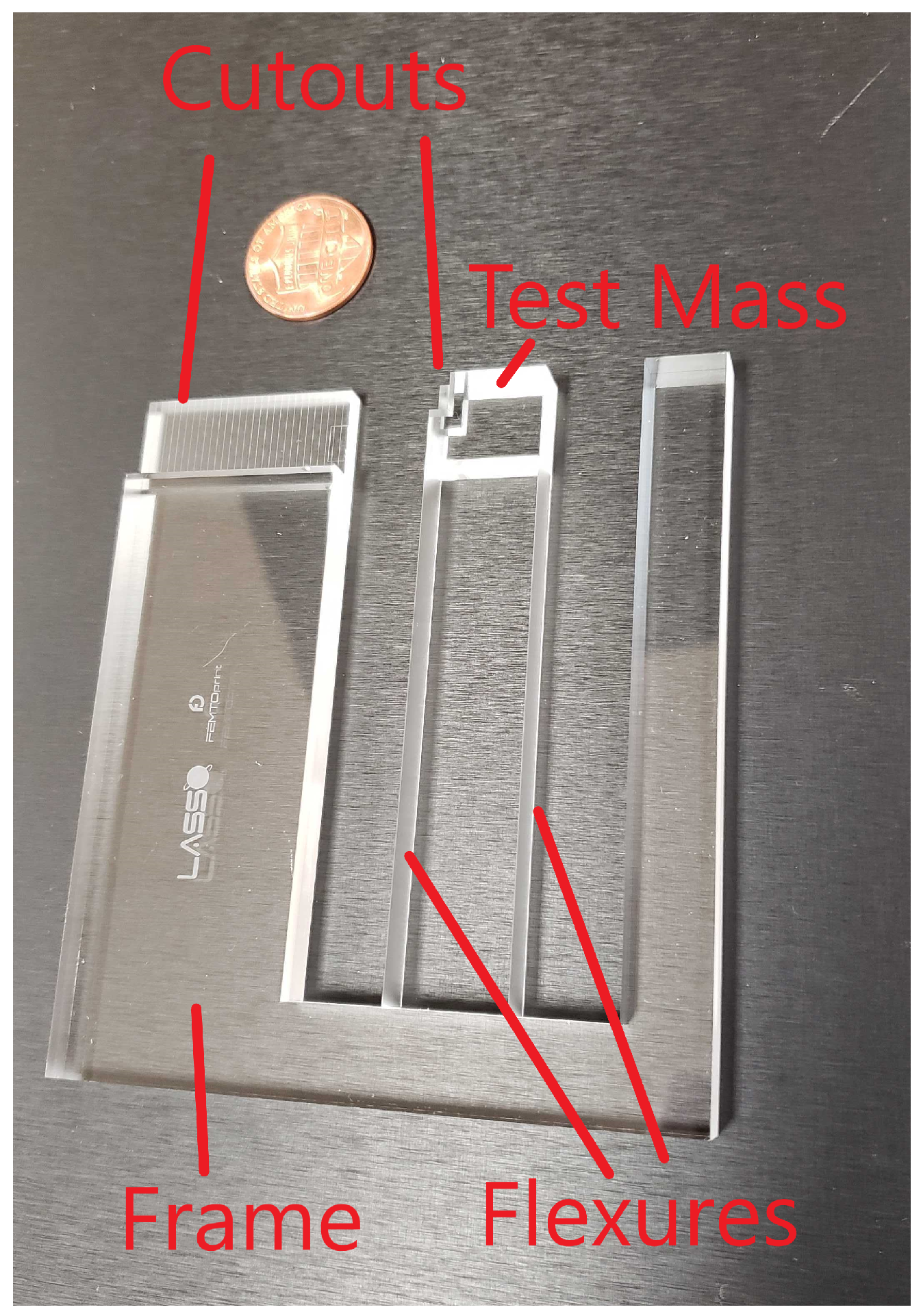
Figure 1. A diagram of our 5 Hz resonator. A penny is added for reference.
Remotesensing 14 04389 g001
Figure 2. The first two eigenmodes of our 5 Hz resonator modeled in COMSOL. Note that the second mode is larger than the first by a factor of more than 10. Having higher-order modes that are substantially higher than the first mode is desired for minimizing the cross talk between modes observed in measurements.
Remotesensing 14 04389 g002
Figure 3. Decay envelope of our ringdown measurement fitted to an exponential. The resonant frequency was removed with a low-pass filter, allowing us to calculate a Q-factor of 4.76(3) × 105.
Remotesensing 14 04389 g003
Figure 4. A diagram of the heterodyne readout used for our measurements. In this schematic, the mirrors M and M R are stationary while M M is the mirror on the test mass.
Remotesensing 14 04389 g004
Figure 5. A plot of the displacement noise in our heterodyne interferometer. As this measurement was taken without our resonator, seismic noise was not present in the data. The shaded area represents the estimated error bars of the spectrum.
Remotesensing 14 04389 g005
Figure 6. (a) The acceleration noise floor of our optomechanical accelerometer including thermal motion from the resonator and readout noise from the laser interferometer. (b) The corresponding displacement readout noise floor required to observe this acceleration noise level. Both plots assume a mechanical Q-factor of 4.76 × 10⁵ and a readout noise consistent with that achieved by LISA Pathfinder [30].
Remotesensing 14 04389 g006
Figure 7. (a) An image of our experimental setup, including our fused silica resonator, heterodyne laser interferometer, and delay-line interferometer. (b) An image of the commercial seismometer’s setup relative to our vacuum chamber, which houses the items shown in (a).
Remotesensing 14 04389 g007
Figure 8. The acceleration noises measured by our optomechanical accelerometer and Trillium Horizon 120 seismometer. We observe good agreement between 100 mHz and 500 mHz. The shaded areas represent the estimated error bars of the spectra.
Remotesensing 14 04389 g008
Figure 9. The transfer function between vacuum chamber temperature and acceleration. Note that between 300 μHz and 50 mHz, the amplitude varies by a factor of nearly 5, suggesting that a linear regression would not be suitable for this data set. The transfer function is not plotted below 300 μHz because the low number of averages causes large uncertainties. The shaded area represents the estimated error bars of the spectrum.
Remotesensing 14 04389 g009
Figure 10. The magnitude of the coherence between our vacuum chamber temperature and our resonator’s acceleration data. The coherence is greater than 0.8 between 0.3 mHz and 60 mHz, indicating that temperature is a significant noise source. The coherence function is not plotted below 300 μHz because the low number of averages causes large uncertainties. The shaded area represents the estimated error bars of the spectrum.
Remotesensing 14 04389 g010
Figure 11. (a) The amplitude spectral density of a seismic measurement taken with our optomechanical accelerometer alongside the noise contributions from laser frequency fluctuations, barometric pressure, and vacuum chamber temperature. Shown also is the residual after removing all three noise sources, demonstrating a significant reduction in noise from 0.2 mHz to 100 mHz and below 100 μHz. (b) A comparison of the postcorrected resonator data to the seismometer data. The good agreement between the two devices now extends down to 1 mHz. The shaded areas represent the estimated error bars of the spectra.
Remotesensing 14 04389 g011
Figure 12. The magnitude of the coherence between our postcorrected resonator data and seismometer data both before and after removing environmental noises. It can be seen that by removing temperature, pressure, and laser frequency fluctuations from the resonator data, the coherence above 1 mHz improves significantly. The shaded areas represent the estimated error bars of the spectra.
Remotesensing 14 04389 g012
Figure 13. A 1000-s-long subset of the acceleration time series obtained by our optomechanical accelerometer and seismometer, in which we see excellent agreement between the two time series. Both traces are high-pass filtered above 0.8 mHz for better comparison of the frequency band with high coherence.
Remotesensing 14 04389 g013
Figure 14. The projected noise floor of our optomechanical accelerometer compared to those of other technologies, including the GRACE [3] and GRACE-FO [4] accelerometers and the Geotech S-13, Trillium 120, and Trillium 360 seismometers [37]. Two traces are plotted for the noise floor of our accelerometer: our current best estimate using our experimental value of the Q-factor, and our resonator design using a value of Q calculated using models for the loss mechanisms of fused silica.
Remotesensing 14 04389 g014
Figure 15. (a) A visualization of our quasi-monolithic interferometer integrated onto the wafer of our resonator. A US nickel is included for scale. (b) A rendering of a triaxial accelerometer concept. This design consists of two layers: the top containing resonators oscillating in the x and y-axes and the bottom with a resonator operating along the z-axis.
Remotesensing 14 04389 g015
Figure 16. (a) A close-up of the z-axis test mass and its flexures. Note that the flexures are not at the midpoint of the wafer but have different offsets to increase the stiffnesses and frequencies of tip-tilt modes. (b) The tip-tilt mode of the z-axis resonator as seen from the underside of the three-axis resonator. The colors indicate the total displacement, with light green being the stationary and purple being the largest displacement.
Remotesensing 14 04389 g016
Publisher’s Note: MDPI stays neutral with regard to jurisdictional claims in published maps and institutional affiliations.