Technical Note

A Two-Step Block Adjustment Method for DSM Accuracy Improvement with Elevation Control of ICESat-2 Data

1
College of Surveying and Geo-Informatics, Tongji University, 1239 Siping Road, Shanghai 200092, China
2
Shanghai Aerospace Electronic Technology Institute, Shanghai 201109, China
3
College of Information Technology, Shanghai Ocean University, 999 Huchenghuan Road, Pudong New District, Shanghai 201306, China
*
Author to whom correspondence should be addressed.
Remote Sens. 2022, 14(18), 4455; https://doi.org/10.3390/rs14184455
Submission received: 2 August 2022 / Revised: 1 September 2022 / Accepted: 1 September 2022 / Published: 7 September 2022
(This article belongs to the Section Earth Observation Data)

Abstract

:
Digital surface models (DSMs) have been widely utilized in various applications as fundamental geographic information data. Block adjustment is normally performed on satellite images to enhance the geometric accuracy and DSMs are then generated by stereo mapping. However, new errors may be introduced during the stereo mapping processing and geometric discrepancies between DSMs may still exist. In particular, block adjustment is difficult for multisource satellite images. Therefore, this paper presents a two-step block adjustment approach directly performed on DSMs, with high-accuracy ICESat-2 laser altimetry data used as elevation control. In the method, DSM tie-point matching, elevation control/check point selection from ICESat-2 laser points, and planar and elevation block adjustments are performed in sequence. In the experiments, ZY-3 satellite stereo images and corresponding generated DSMs, as well as SRTM and ALOS DSMs, are used for verification. The experimental results show that the absolute elevation accuracy and the relative geometric consistency of the DSMs are both significantly improved after two-step DSM block adjustment and it can efficiently improve the accuracy, not only for DSMs acquired by the same sensor type, but also for DSMs acquired by different sensor types, which demonstrates the feasibility and advantage of the proposed method.

Graphical Abstract

1. Introduction

Digital surface models (DSMs) have wide applications in the fields of surveying and civil engineering and are extremely important data for geographic information systems and remote sensing technology [1]. Stereo mapping using remote sensing images is a common way to generate DSMs [2]. However, the process of acquiring remotely sensed images is affected by the observation mode, atmospheric transmission, topographical fluctuations, various sensor factors, etc., all directly impacting the quality of the generated DSM [3,4]. The common approach used to improve an image’s geometric accuracy for DSM generation is to perform block adjustment based on a rational function model (RFM) [5,6,7]. For instance, the block adjustment for the ZY-3 images is performed using laser altimetry data for the elevation constraint [8,9]. Auxiliary topographic data such as elevations extracted from the Shuttle Radar Topography Mission (SRTM) DEM can be taken as the initial value of the object elevation of the image tie points, achieving an overall improvement of the elevation positioning accuracy in large-scale image block adjustment [10,11]. Image-based block adjustment is generally suitable for homologous images. However, there are likely to be systematic deviations between DSMs generated by multisource images. Additionally, errors can be propagated throughout the workflows of image stereo mapping processing for DSM generation. Therefore, many studies have been conducted to improve the accuracy of DSMs.
ASTER GDEM data are corrected by using ICESat (Ice, Cloud, and land Elevation Satellite) laser altimetry data [12], where the DEM artefacts and anomalies are removed using a segment-based outlier detection algorithm in order to correct the mosaiced DEM. For the fusion of multisource DEMs, the geometric consistency of DEMs is improved by using the elevation-error-based weights to determine the influence of each DEM in the fusion process [13,14], for which a priori accuracy information is needed. A rapid mosaicking method for InSAR-generated DSMs was proposed [15] that adopted the elevation correction model, which was determined based on error characteristics during interferometric processing [16]. For the TanDEM-X mission, block adjustment was performed using ICESat laser altimetry data as the constraint [17] and, based on analysis of the DSM elevation error generated in the interferometric processing workflow, the error correction model for block adjustment was set to refine the DSMs. However, if the DSMs have large initial location error, block adjustment using only elevation adjustments is insufficient due to the misalignment of the laser points and the DSM.
Compared with the full-waveform lidar system carried by ICESat, the Advanced Topographic Laser Altimeter System (ATLAS) carried by ICESat-2, which was launched in 2018, has higher accuracy and a smaller laser footprint [18,19]. High-accuracy elevation control points were extracted from ICESat-2 ATL08 data, which can be utilized as high-precision elevation reference data [20,21,22]. This paper addresses the fusion and accuracy improvement of multisensory DSMs and presents a two-step block adjustment method with ICESat-2 laser altimetry data as the elevation control to improve accuracy in both planar and elevation measurements.

2. Methodology

The flowchart of the proposed method is shown in Figure 1. For input DSMs, tie-point matching is conducted first. It is worth noting that the original positioning error of the DSM will result in misalignment between DSM pixels and ICESat-2 data. Therefore, planar block adjustment must be conducted first, followed by elevation control data extraction and elevation block adjustment. The elevation control and check points for the block adjustment are selected from ICESat-2 data according to multiple criteria.

2.1. DSM Tie-Point Extraction

The acquired DSMs contain elevation and position errors. The extraction of tie-points needs to consider the influence of these two errors. The elevation contained in the DSM raster represents the terrain information, which can be utilized for tie-point extraction. A moving window is applied to extract the initial tie-points in the overlapping region of DSMs. Then, the elevation’s standard deviation, as a relatively robust and efficient descriptor, is adopted to achieve extraction of tie-points [15]. Moreover, bilinear interpolation is used to obtain subpixel-level tie-points. Ultimately, the random sampling consistency (RANSAC) algorithm is performed to eliminate the mismatched tie-points.

2.2. Elevation Control/Check Points Selection from ICESat-2 Laser Altimetry Data

The ATL08 data are the Level-3A product of the ICESat-2 altimetry data and contain the land and canopy elevations with elevation accuracies better than 1 m after selection [18]. In the literature [21,22], the impact of various evaluation labels (atmospheric attenuation, surface reflectance, terrain slope, etc.) on the accuracy of ATL08 terrain elevation was analysed, providing reference regarding which label should be considered for elevation control points selection. In our method, the ICESat-2 ATL08 data are first filtered to match the region of the target DSM and then filtered further according to the comprehensive elevation attributes that reflect the elevation precision. The ICESat-2 ATL08 data filtering method in [20] is adopted for first-step selection. It is worth mentioning that the selection criterion in our method is more stringent so as to ensure the high quality of the selected laser points, as shown in Table 1. The points with values for the Cloud_flag_atm attribute less than 1 are preserved, and the height difference between the median terrain elevation and DSM is limited to less than 30 meters. Then, the surface slope, fitted by the photon elevations in the ATL08 segments, is set to less than 2° so that the retained data should locate at flat terrain. For block adjustment, excessively dense points do not significantly improve the block adjustment results [9]. Therefore, a grid is set to evenly distribute the ATL08 data, and only one ATL08 laser point is ultimately retained in each grid cell. The grid size setting has a large tolerance, and in our method the grid size is set to 1/20 of the smaller of the width or height for input DSMs (For example, we set the grid size 2.85 km for the ZY-3 DSM with a size of 61.8 km × 57 km). Moreover, considering the uncertainty in DSM horizontal accuracy, for the DSM pixel containing the control point location, we count the elevation standard deviation between the target pixel and the surrounding pixels within a window size defined according to the initial horizontal error. The threshold of the standard elevation deviation is set as 0.7 (equal to tan (2°) × 20 m) for a DSM with 20 m resolution so that the DSM pixel is in a relatively flat region, as illustrated in the dashed box of Figure 1.

2.3. Two-Step DSM Block Adjustment

We propose a two-step DSM block adjustment approach to enhance the position accuracy of DSMs. First, planar block adjustment is performed by utilising the constraints of the consistency of the geographic coordinates of the tie-points. For DSMs, the geographic coordinates of each grid cell are determined by the geodetic coordinates of the corner point and the resolution in the lateral and longitudinal directions. The six-parameter affine transformation model is adopted to optimize the positioning parameters of each DSM, as shown in Equation (1).
[ X Y ] = ( a 11 a 12 a 21 a 22 ) [ x y ] + [ d x d y ]
where X and Y correspond to the geographic coordinates of a certain grid cell of the DSM; x and y are the corresponding row and column numbers; d x and d y are the latitude and longitude of the corner points of the DSM. That is, the planar block adjustment will optimize the location of the DSM, including the corner point coordinates and the A matrix (representing the rotation parameter and the scale parameter).
Second, DSM elevation block adjustment is conducted after planar block adjustment to correct the relative elevation inaccuracy between adjacent DSMs. The parameters of the elevation error model for each DSM are optimized by the constraint of the elevation control points. Simultaneously, tie-points of the overlapping region are utilized to establish the consistency restrictions of DSM pixels. For satellite images, there are biases in the RFM coefficients owing to observation or sensor orientation errors [2]. The discrepancies between the measured and nominal line and sample coordinates are generally characterized as polynomial models of the image line and sample coordinates [5]. For input DSMs, the initial elevation error is first evaluated by the ATL08 check points. Then, the order of the polynomial model is determined by the elevation error distribution calculated by the extracted ATL08 data, as shown in Equation (2).
g ( x i , y i ) = a 0 + a 1 x i + a 2 x i 2 + a 3 x i 3 + a n x i n + b 1 y i + b 2 y i 2 + b 3 y i 3 b n y i n
where g ( x i , y i ) represents the elevation correction value and a i and b i are the model parameters corresponding to the DSM row and column numbers. For a certain tie-point pair ( x J , y J ) and ( x K , y K ) on DSM J and K, respectively, the block adjustment constraint is that their final elevations are equivalent after corresponding elevation correction, as shown in Equation (3).
h D E M _ J ( x J , y J ) g J ( x J , y J ) = h D E M _ K ( x K , y K ) g K ( x K , y K )
where g J ( x J , y J ) is the elevation correction value of DSM J, g K ( x K , y K ) is the corresponding value of DSM K. h D E M _ J ( x J , y J ) is the initial elevation of DSM J at location ( x J , y J ) , and h D E M _ K ( x K , y K ) is the elevation of DSM K at location ( x K , y K ) . Combined with the constraint on the control points, the observation equation can be written as Equation (4).
V = A X H e r r o r
where X = [ a J 0 a J 1 a J a J n b J 1   b J b J n a K 0 a K 1 a K a K 3 b K 1   b K   b K n ] T   is the coefficient vector of the elevation correction model.
A = [ H G C P _ J 0 0 H G C P _ k H T P _ J H T P _ K ]
The first two lines ( H G C P _ J and H G C P _ K ) of matrix A indicate that ICESat-2 control data are utilized to improve DSM J and K, respectively. The third line ( H T P _ J and H T P _ K ) indicates the elevation constraints between the tie-points of adjacent DSMs. These matrices have the same form consisting of different orders of row and column numbers as follows:
H G C P _ J = [ 1 x G C P 1 _ J x G C P 1 _ J 2 . 1 x G C P 2 _ J x G C P 2 _ J 2 . . . . . . . . . 1 x G C P m _ J x G C P m _ J 2 . x G C P 1 _ J n x G C P 2 _ J n . . x G C P m _ J n y G C P 1 _ J y G C P 1 _ J 2 . y G C P 1 _ J n y G C P 2 _ J y G C P 2 _ J 2 . y G C P 2 _ J n . . . . . . . . y G C P m _ J y G C P m _ J 2 . y G C P m _ J n ]
Then, the coefficients of the error correction model can be obtained by using the least square principle to eliminate the elevation system error of each DSM.

2.4. Accuracy Assessment

First, to intuitively compare the results between the block adjustment performed on the image space and the method directly conducted on DSMs proposed in this paper, corresponding DSMs are generated from the refined images by stereo mapping after the RFM-based image block adjustment [8,9,23,24]. The elevation check points are utilized to evaluate the elevation accuracy of DSMs generated by the two methods.
Then, the accuracy evaluation of the experimental results was carried out for two aspects for the ICESat-2 data-aided DSM block adjustment. On the one hand, plane block adjustment optimizes the coordinates of the corner points and the rotation parameters of DSMs. Therefore, the difference between the geographic latitude and longitude coordinates of the tie-points will be estimated before and after the block adjustment, corresponding to the relative planar error, and the height difference of the tie points correspond to the relative elevation error. On the other hand, the overall elevation accuracy of the DSM is enhanced through the constraint of the elevation consistency of the tie-points (improve the relative elevation accuracy) and the constraint of the ATL08 control points. Therefore, to assess the height accuracy evaluation of the DSMs before and after the block adjustment, the RMSE of the elevation difference between the check points (randomly chosen from the retained ICESat-2 data) and the corresponding DSM grid is calculated.

3. Study Area and Experimental Data

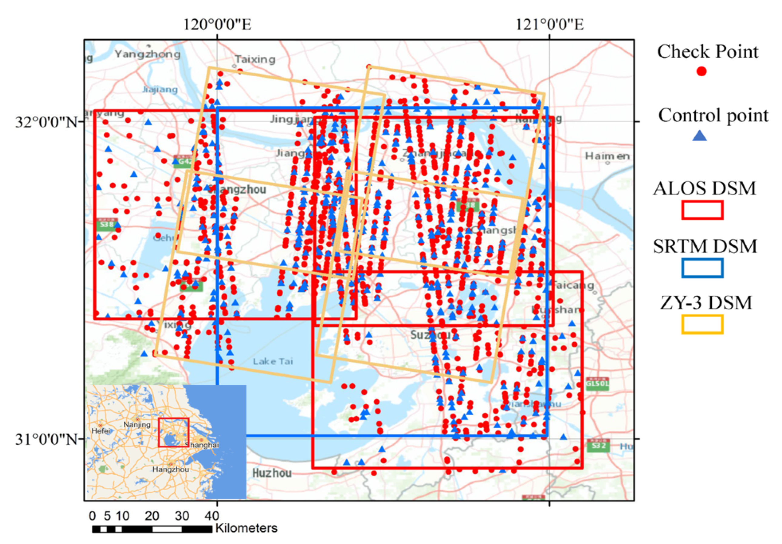
Based on the collected ZY-3 images acquired in April 2016 over the Taihu Lake Basin, which includes urban and suburban areas and where the terrain is mainly plain with some hilly areas, the corresponding DSMs with a resolution of 10 m are generated using the ZY-3 backward and forward images and the coverage is illustrated in Figure 2. To demonstrate the effectiveness of the proposed block adjustment method for multisensory DSM data, elevation data are 1extracted from SRTM data, with a 30 m resolution, and ALOS PALSAR DSM data, with a resolution of 12.5 m, both of which have absolute elevation accuracy within 10 m [25,26]. The coordinate system of all the experimental DSMs is based on the WGS84 datum. Moreover, the ICESat-2 ATL08 data that overlaps with the area of the DSMs acquired in a period from October 2018 are acquired and filtered to serve as elevation control and check points, which is the available earliest data since its launch, so that the altimetry data time is as close as possible to the DSM acquisition time to avoid, as much as possible, terrain change due to human activities. The height accuracy of the ATL08 data is 0.2 m in the plain area [20,27].

4. Experimental Results

4.1. Elevation Control and Check Point Selection and Elevation Correction Model Detection

The ATL08 data are first filtered to generate elevation control and check points. Considering the preliminary positioning error of the collected DSMs, we set a window with a size of 7 × 7 pixels to restrict the topographic relief around the target DSM grid cell that corresponds to the control point (this parameter has a large tolerance because we no longer need many elevation control points). The distribution of the ATL08 control and check points after the selection are illustrated in Figure 2. A total of 55,119 points are preliminarily acquired in the DSM region. After setting the threshold and a 280 × 280 grid for evenly distributed control points, 1314 ATL08 control points are reserved, one-third of which are randomly selected as the check points. The first-order and second-order polynomial models are adopted to rectify the elevation error for the near-linear and systematic elevation error distribution, which is in contrast with the ICESat-2 data. The accuracy of these two models has been compared in the block adjustment experiments for DSMs with control points, affirming in advance that the experimental results prove that the accuracy of the second-order polynomial is relatively higher. Therefore, if there is no explanation, we uniformly adopt the second-order polynomial model to suit the elevation error of DSMs.

4.2. Comparison of GCP-Free Block Adjustment Conducted on Image and Object Space

To verify the effectiveness of the proposed two-step block adjustment approach carried out on the object space, GCP-free DSM block adjustment is performed for equal comparison with the RFM-based image block adjustment method [7,24]. Through the uncontrolled block adjustment of the ZY-3 original images, corresponding DSMs are generated by performing stereo mapping for subsequent accuracy comparison. Simultaneously, uncontrolled block adjustments are performed by the proposed approach on DSMs generated by the original ZY-3 images. The accuracy of the DSMs generated before and after the block adjustment by these two strategies are in contrast, as illustrated in Figure 3. The histograms of the DSM elevation errors from the check data are acquired before and after the GCP-free block adjustments with the two methods, as shown in Figure 4a–c. Evaluated through the checkpoints, the accuracies of these two strategies conducted in image or object space are equivalent, as shown in Table 2, with RMSEs of 7.00 m and 5.85 m. Therefore, it is difficult to confirm that uncontrolled block adjustment clearly improves absolute elevation accuracy. Both block adjustment results indicate the capability to correct the elevation disagreements in the overlapping DSMs, because their relative elevation error was reduced from 8.89 m to less than 2 m after block adjustment. For the original DSMs and corresponding results after block adjustment, the locations of tie-points are calculated, with the RMSE of the planar location error decreasing from 13.45 m initially to 3.26 m (DSMs after uncontrolled image block adjustment) and 3.11 m (after uncontrolled block adjustment directly in object space). For each DSM, since the ZY-3 images are obtained by stitching the data acquired by the block CCD, there will be elevation inconsistencies inside the DSMs, and this internal error is temporarily ignored. In addition, since it is difficult to precisely match the ICESat-2 data and the optical images, and the focus of this paper is to prove the effectiveness of the block adjustment in object space, the block adjustment experiment with control points conducted on images is not performed for comparison with the adjustment in object space.

4.3. Block Adjustment Results Conducted on DSMs with Elevation Control

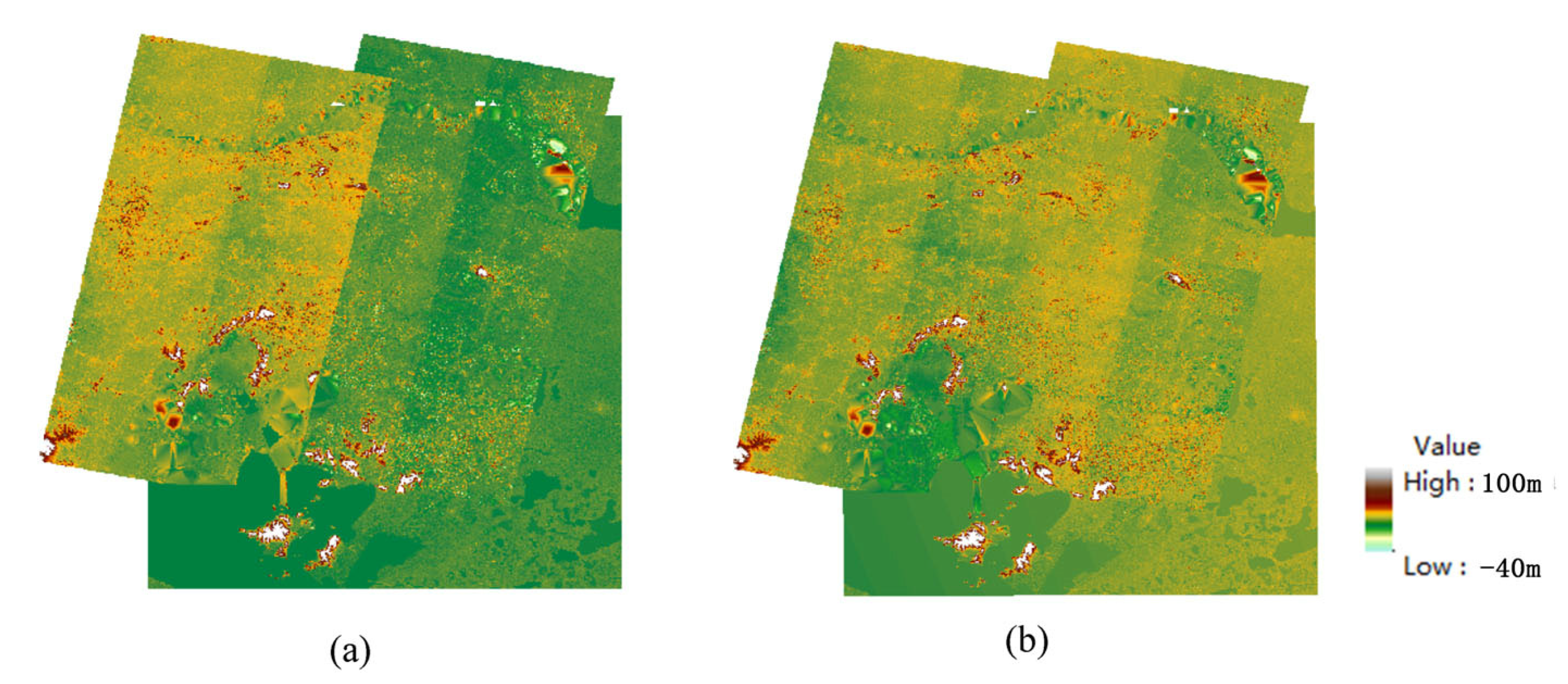
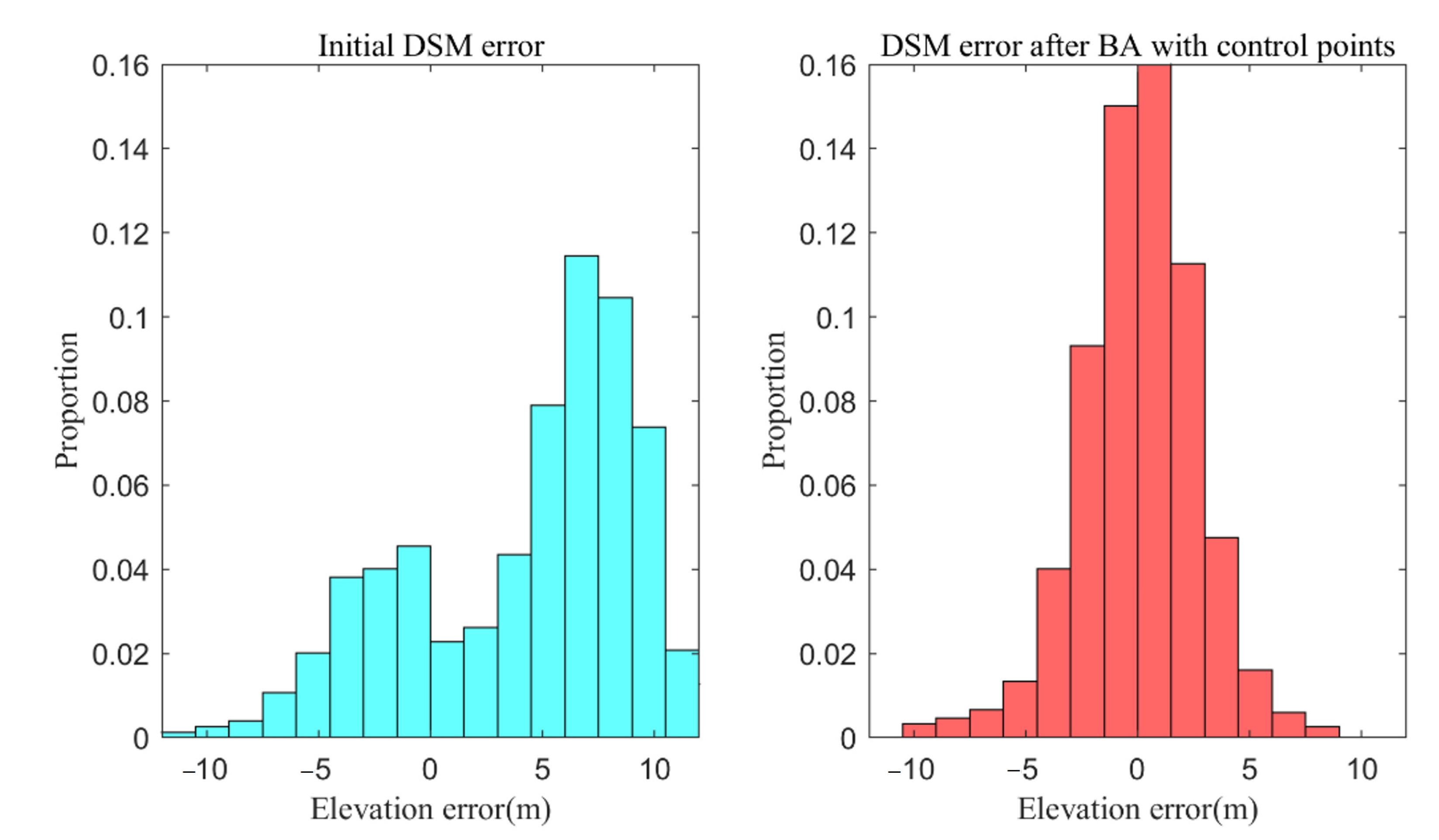
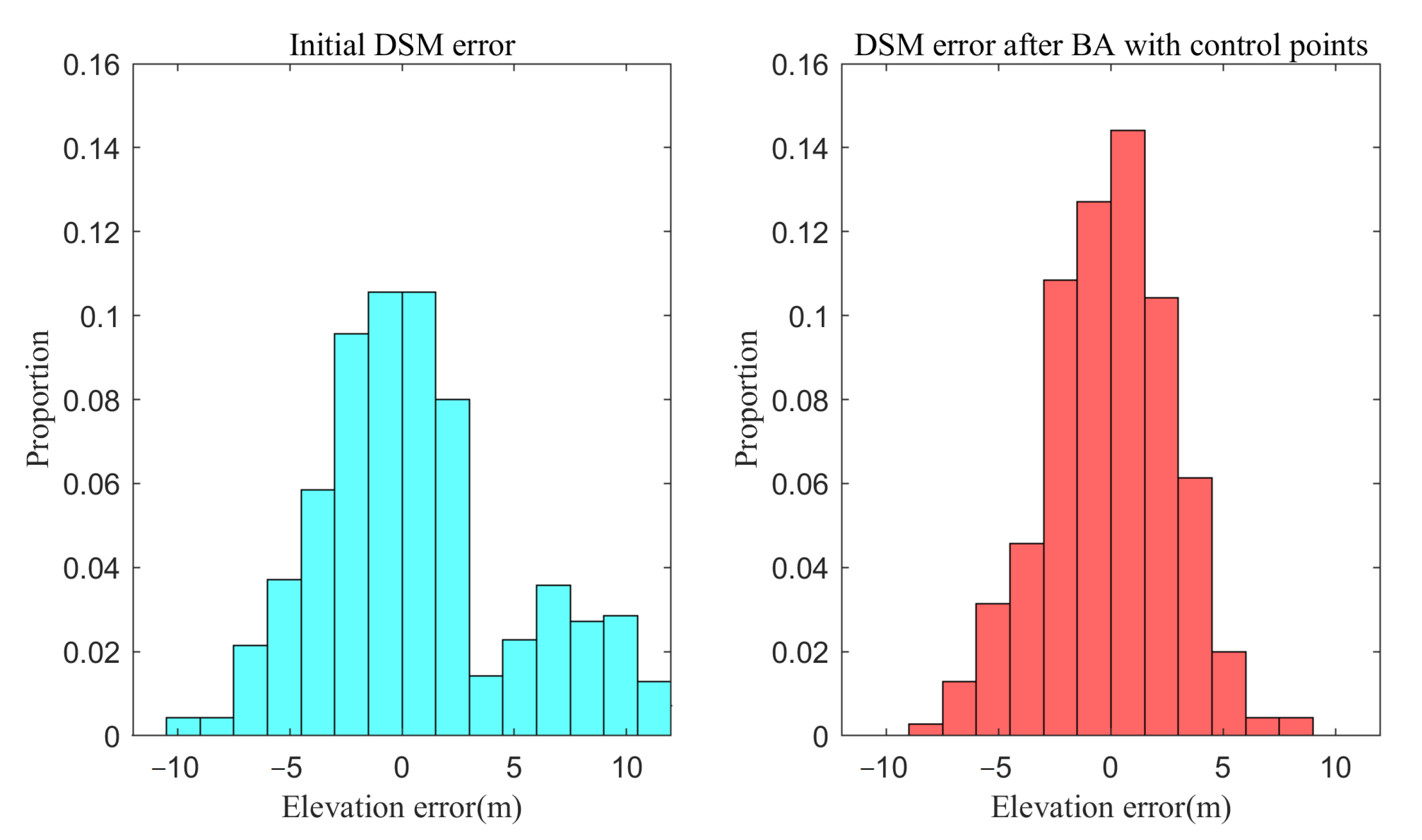
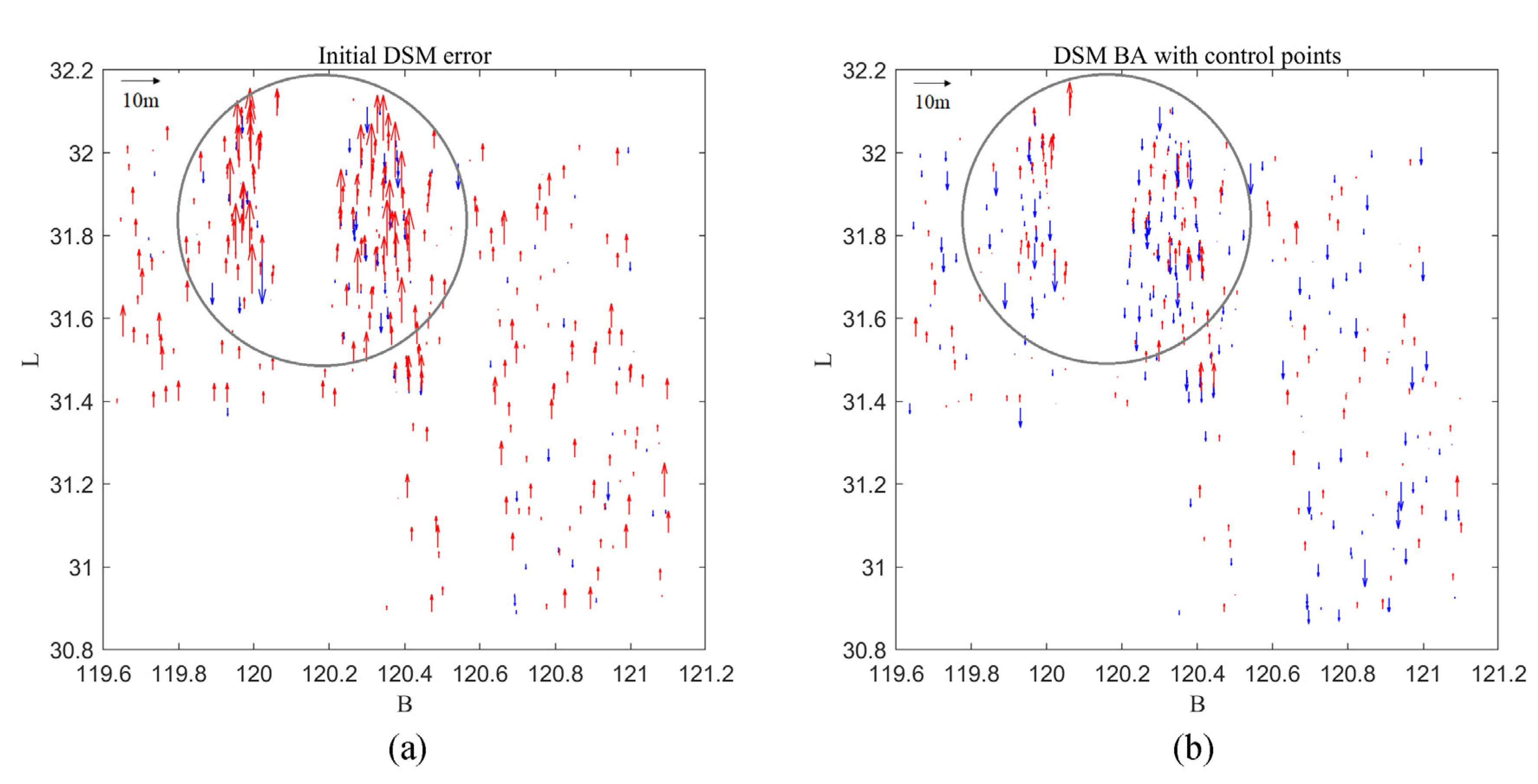
We have demonstrated through uncontrolled block adjustment that the proposed two-step block adjustment conducted on object space can also enhance the elevation uniformity of DSMs. To further make use of the ICESat-2 laser altimetry data, block adjustments with elevation control points are subsequently carried out. We first compared the results of block adjustment with control points by adopting the first-order and second-order polynomial elevation error models. As shown in Table 2, the block adjustment results obtained from the second-order polynomial are significantly better. Therefore, a second-order polynomial is adopted as the regression model to fit the systemically distributed elevation errors of DSMs. Because the usage of control points will bring extra influence on the parameters of elevation correction model, the deviation of elevation between tie-points after uncontrolled DSM block adjustment is smaller than that with control points. Figure 3a,d contrasts the ZY-3 DSMs before and after block adjustment and the introduction of the elevation control points. The distribution histogram of DSM elevation errors derived from check points is obtained before and after the block adjustments (with and without control points), as shown in Figure 4b,d. After block adjustment with elevation control points using the second-order elevation error model, the mean elevation error of the check points decreased from 3.18 m to 0.55 m, and the RMSE of the elevation error decreased from 7.62 m to 2.60 m. Figure 5a–d illustrates the error distribution of check points in the DSMs corresponding to the results in Figure 3. It can be seen that systematic errors remained after block adjustment from the image and object space without control points, whilst Figure 5d indicates that the overall elevation accuracy is considerably improved after the additional elevation constraint.

4.4. Block Adjustment Results are Conducted on Multisource DSM with Elevation Control

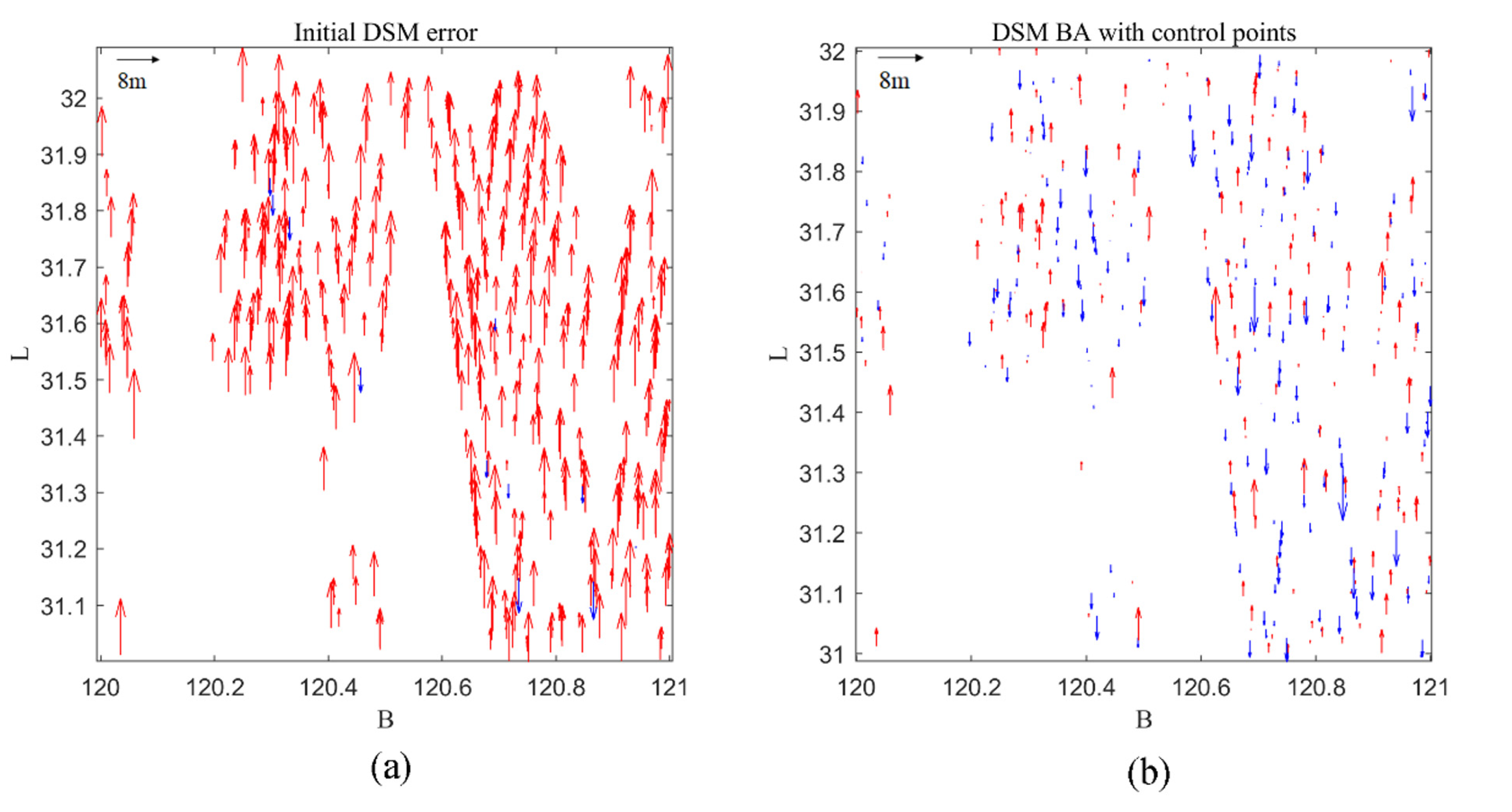
To further confirm the suitability of our proposed method for multisensory DSMs, block adjustment experiments among SRTM, ALOS and ZY-3 DSMs are conducted. For the multisensory DSM block adjustment processing, we resampled SRTM DSMs and ALOS DSMs to make the resolution consistent with ZY-3 DSMs. Figure 6 and Figure 7 illustrate the block adjustment results for the SRTM DSM from the aspect of the overall elevation consistency of the DSMs and the elevation error histogram of the check points, respectively. Figure 8 illustrates the error distribution of check points in the DSMs corresponding to the results in Figure 6. To avoid confusion with the check points of ZY-3, only the check points on the SRTM are exhibited. A systematic elevation deviation of more than 5 meters is shown, which is well corrected after block adjustment.
Figure 9 and Figure 10 illustrate the block adjustment results for ALOS DSMs. The elevation error distribution with a mean close to 0 revealed in the histograms demonstrated the effectiveness of the block adjustment. According to the elevation accuracy evaluation results of the checkpoints in Table 3, the ALOS DSMs with higher resolution have a higher initial elevation accuracy of 2.06 m, and the overall improvement of 41% is less noticeable than that of SRTM, 61%. Both the relative elevation errors calculated by the tie-points are reduced to less than 1.5 m after block adjustment. The accuracy of planar location also has a significant improvement after block adjustment, which is within a pixel. The error of check points for ALOS is presented in Figure 11, which also proves the improvement of elevation accuracy after block adjustment, and it can be seen that the initial elevation accuracy of ALOS is relatively higher than SRTM. However, due to the difference in sensors, the elevation of the DSM overlapping region is not as consistent as that of the homologous-source DSMs. Additionally, due to the lack of texture and various imaging mechanisms, the elevation consistency in the lake area between the original ZY-3 and SAR DSMs is relatively obvious, as illustrated in the lower left corners of Figure 6 and Figure 9.

5. Discussion

The method in this paper clearly improves the consistency and position accuracy of multisource DSMs by two-step block adjustment from the object space. Through the experimental results of block adjustment without the constraint of control points, it has been demonstrated that the proposed approach considerably improves the results as compared with the traditional correction method based on block adjustment conducted in image space. In the absence of control points, the two methods do not significantly improve the absolute accuracy of the DSM elevation, but the geometric consistency of the overlapping areas is significantly improved. However, block adjustment from the object space has the following advantages. On the one hand, block adjustment from the object space can directly register the multisource DSMs with the terrain information, avoiding complex matching processing between multisource images. On the other hand, for the ICESat-2 control data, it is easier to effectively match the 3D terrain contained in the DSM data, while the traditional block adjustment in image space requires the referenced footprint images of control data for registration. Moreover, it can be seen from the experiment that our method can improve the absolute accuracy of the multisource DSMs by more than 40% using the ICESat-2 control data as a constraint, and the consistency of the overlapping area is also improved significantly.

6. Conclusions

This paper proposes a two-step DSM block adjustment method using ICESat-2 ATL08 data as the elevation control. By calculating the elevation difference between the elevation check points and DSMs and the location deviation of the tie points, it has been demonstrated that the elevation accuracy and geometric consistency of the input DSMs have been greatly improved after block adjustment. The SRTM and ALOS DSMs generated from SAR have been utiliz2ed for experiments as multisource DSMs, and the experimental results have verified the feasibility and advantage of the proposed block adjustment method for improving the geometric consistency and quality of multisource DSMs.

Author Contributions

Conceptualization, X.Z., S.L. and X.T.; methodology, X.Z., S.L., B.X., H.X., Z.H. and R.D.; software, X.Z.; writing—original draft preparation, X.Z. and S.L.; writing—review and editing, X.Z., B.X., S.L., X.T., R.D., H.X. and Z.H.; supervision, X.T. and S.L.; funding acquisition, S.L. and X.T. All authors have read and agreed to the published version of the manuscript.

Funding

This research was jointly supported by Ministry of Science and Technology of the People’s Republic of China (Project No. 2017YFA0603100), the National Natural Science Foundation of China (Project Nos. 42171432 and 41771483), Shanghai Science and Technology Project (Project No. 21511103800), Shanghai Municipal Science and Technology Major Project (Project No. 2021SHZDZX0100), and Fundamental Research Funds for the Central Universities.

Data Availability Statement

Data underlying the results presented in this paper are not publicly available at this time but may be obtained from the authors upon reasonable request.

Acknowledgments

The authors would like to express gratitude to the anonymous reviewers for their valuable comments and suggestions, which helped improve the quality of this paper.

Conflicts of Interest

The authors declare no conflict of interest.

References

  1. Okolie, C.J.; Smit, J.L. A systematic review and meta-analysis of Digital elevation model (DEM) fusion: Pre-processing, methods and applications. ISPRS J. Photogramm. Remote Sens. 2022, 188, 1–29. [Google Scholar] [CrossRef]
  2. Luethje, F.; Tiede, D.; Eisank, C. Terrain Extraction in Built-Up Areas from Satellite Stereo-Imagery-Derived Surface Models: A Stratified Object-Based Approach. ISPRS Int. J. Geo Inf. 2017, 6, 9. [Google Scholar] [CrossRef]
  3. Fisher, P.F.; Tate, N.J. Causes and consequences of error in digital elevation models. Prog. Phys. Geogr. Earth Environ. 2016, 30, 467–489. [Google Scholar] [CrossRef]
  4. Jinaya Gong, Z.L.; Qing, Z.; Haigang, S.; Yi, Z. Effects of Various Factors on the Accuracy of DEMs: An Intensive Experimental Investigation. Photogramm. Eng. Remote Sens. 2000, 66, 1113–1117. [Google Scholar]
  5. Grodecki, J.; Dial, G. Block Adjustment of High-Resolution Satellite Images Described by Rational Polynomials. Photogramm. Eng. Remote Sens. 2003, 69, 59–68. [Google Scholar] [CrossRef]
  6. Fraser, C.S.; Hanley, H.B. Bias Compensation in Rational Functions for Ikonos Satellite Imagery. Photogramm. Eng. Remote Sens. 2003, 69, 53–57. [Google Scholar] [CrossRef]
  7. Tong, X.; Liu, S.; Weng, Q. Bias-corrected rational polynomial coefficients for high accuracy geo-positioning of QuickBird stereo imagery. ISPRS J. Photogramm. Remote Sens. 2010, 65, 218–226. [Google Scholar] [CrossRef]
  8. Tang, X.; Zhang, G.; Zhu, X.; Pan, H.; Jiang, Y.; Zhou, P.; Wang, X. Triple linear-array image geometry model of ZiYuan-3 surveying satellite and its validation. Int. J. Image Data Fusion 2013, 4, 33–51. [Google Scholar] [CrossRef]
  9. Li, G.; Tang, X.; Gao, X.; Wang, H.; Wang, Y. ZY-3 Block adjustment supported by glas laser altimetry data. Photogramm. Rec. 2016, 31, 88–107. [Google Scholar] [CrossRef]
  10. Zhang, Y.; Wan, Y.; Huang, X.; Ling, X. DEM-Assisted RFM Block Adjustment of Pushbroom Nadir Viewing HRS Imagery. IEEE Trans. Geosci. Remote Sens. 2016, 54, 1025–1034. [Google Scholar] [CrossRef]
  11. Zhou, P.; Tang, X.; Wang, Z.; Cao, N.; Wang, X. SRTM-assisted block adjustment for stereo pushbroom imagery. Photogramm. Rec. 2018, 33, 49–65. [Google Scholar] [CrossRef]
  12. Arefi, H.; Reinartz, P. Accuracy Enhancement of ASTER Global Digital Elevation Models Using ICESat Data. Remote Sens. 2011, 3, 1323–1343. [Google Scholar] [CrossRef]
  13. Jiang, H.; Zhang, L.; Wang, Y.; Liao, M. Fusion of high-resolution DEMs derived from COSMO-SkyMed and TerraSAR-X InSAR datasets. J. Geod. 2014, 88, 587–599. [Google Scholar] [CrossRef]
  14. Yue, L.; Shen, H.; Zhang, L.; Zheng, X.; Zhang, F.; Yuan, Q. High-quality seamless DEM generation blending SRTM-1, ASTER GDEM v2 and ICESat/GLAS observations. ISPRS J. Photogramm. Remote Sens. 2017, 123, 20–34. [Google Scholar] [CrossRef]
  15. Hong, Z.; Sun, P.; Zhou, R.; Tong, X.; Feng, Y.; Liu, S. Fast mosaicking method of InSAR-generated multi stripe digital elevation model. J. Infrared Millineter. 2022, 41, 493–500. [Google Scholar]
  16. Gruber, A.; Wessel, B.; Huber, M.; Roth, A. Operational TanDEM-X DEM calibration and first validation results. ISPRS J. Photogramm. Remote Sens. 2012, 73, 39–49. [Google Scholar] [CrossRef]
  17. Birgit Wessela, A.G.; Gonzálezb, J.H.; Bachmannb, M.; Wendleder, A. Tandem-x block adjustment of interferometric height models. In Proceedings of the IGARSS’08, Wessling, Germany, 2008; pp. 111–114. [Google Scholar]
  18. Markus, T.; Neumann, T.; Martino, A.; Abdalati, W.; Brunt, K.; Csatho, B.; Farrell, S.; Fricker, H.; Gardner, A.; Harding, D.; et al. The Ice, Cloud, and land Elevation Satellite-2 (ICESat-2): Science requirements, concept, and implementation. Remote Sens. Environ. 2017, 190, 260–273. [Google Scholar] [CrossRef]
  19. Neuenschwander, A.L.; Magruder, L.A. Canopy and Terrain Height Retrievals with ICESat-2: A First Look. Remote Sens. 2019, 11, 1721. [Google Scholar] [CrossRef]
  20. Li, B.; Xie, H.; Liu, S.; Tong, X.; Tang, H.; Wang, X. A Method of Extracting High-Accuracy Elevation Control Points from ICESat-2 Altimetry Data. Photogramm. Eng. Remote Sens. 2021, 87, 821–830. [Google Scholar] [CrossRef]
  21. Carabajal, C.C.; Boy, J.P. Icesat-2 Altimetry as Geodetic Control. Int. Arch. Photogramm. Remote Sens. Spat. Inf. Sci. 2020, XLIII-B3-2020, 1299–1306. [Google Scholar] [CrossRef]
  22. Moudrý, V.; Gdulová, K.; Gábor, L.; Šárovcová, E.; Barták, V.; Leroy, F.; Špatenková, O.; Rocchini, D.; Prošek, J. Effects of environmental conditions on ICESat-2 terrain and canopy heights retrievals in Central European mountains. Remote Sens. Environ. 2022, 279, 113112. [Google Scholar] [CrossRef]
  23. Cao, N.; Zhou, P.; Wang, X.; Tang, X.; Li, G. Refined processing of laser altimeter data-aided satellite geometry model. J. Remote Sens. 2018, 22, 599–610. [Google Scholar] [CrossRef]
  24. Zhang, G.; Jiang, B.; Wang, T.; Ye, Y.; Li, X. Combined Block Adjustment for Optical Satellite Stereo Imagery Assisted by Spaceborne SAR and Laser Altimetry Data. Remote Sens. 2021, 13, 3062. [Google Scholar] [CrossRef]
  25. Mouratidis, A.; Ampatzidis, D. European Digital Elevation Model Validation against Extensive Global Navigation Satellite Systems Data and Comparison with SRTM DEM and ASTER GDEM in Central Macedonia (Greece). ISPRS Int. J. Geo Inf. 2019, 8, 108. [Google Scholar] [CrossRef]
  26. Shimada, M.; Tadono, T.; Matsuoka, M. Calibration and validation plans for ALOS/PRISM. In Proceedings of the IEEE International Geoscience and Remote Sensing Symposium, Toronto, ON, Canada, 24–28 June 2002; pp. 384–386. [Google Scholar]
  27. Tian, X.; Shan, J. Comprehensive Evaluation of the ICESat-2 ATL08 Terrain Product. IEEE Trans. Geosci. Remote Sens. 2021, 59, 8195–8209. [Google Scholar] [CrossRef]
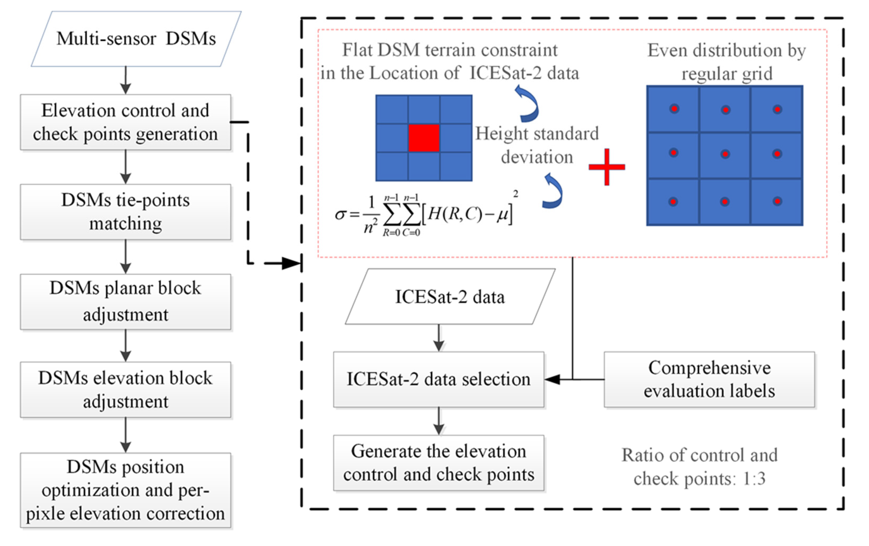
Figure 1. Flowchart of the proposed method.
Remotesensing 14 04455 g001
Figure 2. The distribution of the ZY-3, ALOS and SRTM DSMs (with the location of the elevation control and check points).
Remotesensing 14 04455 g002
Figure 3. Comparison of ZY-3 DSMs before and after block adjustment in object and image space. (a) Original DSMs, (b) uncontrolled DSM block adjustment, (c) uncontrolled image block adjustment, and (d) controlled DSM block adjustment.
Remotesensing 14 04455 g003
Figure 4. Histograms of check point elevation error for the ZY-3 DSMs. (a) before block adjustment, (b) uncontrolled DSM block adjustment, (c) uncontrolled images block adjustment, and (d) controlled DSM block adjustment.
Remotesensing 14 04455 g004
Figure 5. Elevation error distribution on check points for the ZY-3 DSMs (positive errors are indicated by the up-pointing red arrows and negative errors by down-pointing blue arrows). (a) before block adjustment, (b) uncontrolled DSM block adjustment, (c) uncontrolled images block adjustment. (d) controlled block adjustment.
Remotesensing 14 04455 g005
Figure 6. DSM comparison before and after the block adjustment for SRTM and ZY-3 DSM. (a) Before block adjustment, and (b) after block adjustment.
Remotesensing 14 04455 g006
Figure 7. Elevation accuracy of the check points before and after block adjustment for the SRTM and ZY-3 DSMs.
Remotesensing 14 04455 g007
Figure 8. Elevation error distribution on the check points for the SRTM DSMs (positive errors are indicated by the up-pointing red arrows and negative errors by down-pointing blue arrows). (a) before block adjustment, and (b) after block adjustment.
Remotesensing 14 04455 g008
Figure 9. DSM comparison before and after the block adjustment for the ALOS and ZY-3 DSMs with the ellipses indicating the areas of significant difference. (a) Before block adjustment, and (b) after block adjustment.
Remotesensing 14 04455 g009
Figure 10. Elevation accuracy of the check points before and after block adjustment for the ALOS and ZY-3 DSMs.
Remotesensing 14 04455 g010
Figure 11. Elevation error distribution on the check points for the ALOS DSMs (positive errors are indicated by the up-pointing red arrows and negative errors by down-pointing blue arrows), the ellipse indicates the area of significant difference. (a) before block adjustment, and (b) after block adjustment.
Remotesensing 14 04455 g011
Table 1. Description of the evaluation labels.
Attribute LabelDescriptionThreshold Value
h_te_stdThe standard deviation of the photon heights above the WGS84 Ellipsoid, classified as terrain within the segment.h_te_std < 2 m
terrain_slopeThe along-track slope of terrain, within each segment; computed by a linear fit of terrain classified photons.terrain_slope × 100 < 2
h_dif_refDifference between h_te_median and ref_DEMh_dif_ref ≤ 30 m
cloud_flag_atmCloud confidence flag from ATL09 that indicates the number of cloud or aerosol layers identified in each 25 Hz atmospheric profile. If the flag is greater than 0, aerosols or clouds could be present. Valid range is 0–10.cloud_flag_atm ≤ 1
h_te_skewThe skewness of the photon heightsh_te_skew ≤ 1
n_te_photonsThe number of the photons classified as terrain within the segment.(n_te_photons/n_seg_ph) × 100% > 70%
n_seg_phNumber of photons within each land segment.
Table 2. Accuracy of the ZY-3 DSMs before and after block adjustment (BA) (unit: metre).
Mean
Elevation Error
Elevation RMSERelative
Elevation Error
Relative
Planar Error
Before BA3.187.628.8913.45
Uncontrolled image BA7.647.001.963.26
Uncontrolled DSM BA3.715.851.023.11
Elevation-controlled DSM BAFirst-order1.023.541.243.11
Second-order0.552.601.093.11
Table 3. Accuracy of the multisensory DSMs before and after block adjustment (unit: meters).
Input DSMs for BAMean
Elevation Error
Elevation
RMSE
Relative
Elevation Error
Relative
Planar Error
ZY-3 and SRTMBefore BA4.436.809.2737.64
After BA0.872.611.485.65
ZY-3 and ALOSBefore BA2.064.8110.5828.56
After BA0.762.811.254.26
Publisher’s Note: MDPI stays neutral with regard to jurisdictional claims in published maps and institutional affiliations.