1. Introduction
Portland cement concrete is the most widely used construction material in the world. It has excellent compressive strength but is weak under tensile stress. So, it is mostly used as reinforced concrete (RC) in combination with steel reinforced bars, which are strong in tensile stress. However, deterioration of concrete caused by alkali–silica reaction, salt damage, and freeze-thaw has been an issue worldwide, resulting in structural cracking. Generally, the simplest diagnosis of concrete involves visual inspection of surface cracks, but when surface cracks appear due to corrosion of the rebar, the rebar is often quite damaged. So, quality control of concrete is important to improve the strength of concrete and its resistance to intrusion by material. In addition, the combined effects of carbonation, chloride ion penetration, and the thin cover thickness of concrete result in rebar corrosion. Corrosion of rebar is said to be the main cause of deterioration of RC structures [
1] because it magnifies cracks, which further accelerates the rebar corrosion. Thus, prediction and early inspection of corrosion are also important issues.
Destructive core tests are often used to predict corrosion from actual structural investigations because a trigger of rebar corrosion is damage to the protective coating of rebars by a decrease in pH due to carbonation and by the intrusion of chloride ions. On the other hand, since corrosion reactions do not proceed without oxygen and moisture, it is difficult to predict corrosion simply by examining the depth of carbonation and chloride ion intrusion from cores. Thus, other inspection techniques [
2,
3,
4] are required.
In the diagnosis of steel corrosion, electromagnetic nondestructive methods based on eddy current [
5] or resistivity [
6] are often used for directly accessible conditions. Since rebar in concrete cannot be easily accessed, there are many specialized inspection methods for accuracy, rapidity, destructiveness, contactness, resolution, or quantitativeness. The most accurate and quantitative method is the destructive method, in which a concrete core is extracted and directly inspected, but its rapidity and versatility are limited. There are also many semi- or non-destructive inspection techniques, which are well-summarized in [
7]. Semi-destructive techniques, such as surface potential measurement [
8,
9,
10,
11] and the polarization resistance method [
12,
13,
14], have been practically applied to the evaluation of the potential for corrosion and the corrosion rate, respectively. Moreover, the electrical impedance method [
15,
16,
17] is effective and reproducible. However, most semi-destructive methods lack the rapidity, spatial resolution, and quantitativeness.
Elastic wave methods, such as the impact echo method [
18] and the ultrasonic method [
2,
19], are well-known as promising nondestructive methods to evaluate the deterioration of RC structures such as concrete strength and internal defects by using the arrival time, waveform energy, and frequency spectrum of received elastic waves. However, they require elastic wave sensors in contact with the concrete surface, which are strongly affected by the contact condition of the sensors. In addition, since an elastic wave is sensitive to micro cracks in the propagation path, the cracks interrupt or wraparound the elastic wave.
Electromagnetic methods are more effective, nondestructive, and noncontact techniques due to direct assessment of rebars in RC structures as well-reviewed in [
20,
21]. They are classified according to the excitation frequency of the DC to X-ray band. The magnetic flux leakage, eddy current testing [
22,
23], and active thermography [
24,
25,
26] have been practically used for nondestructive inspection of position, cover, diameter, and corrosion of rebars. However, the quantitativeness and spatial resolution should be improved for the evaluation of rebar corrosion in practical situations. Ground Penetrating Radar (GPR) [
27] is another promising technique for detecting rebars due to its simplicity, non-contact, nondestructiveness, high spatial resolution, and practicality. It has also been applied to evaluate rebar corrosion by taking advantage of the fact that the reflection coefficient from rebar decreases with corrosion [
28,
29,
30]. However, since the amplitude information of the radar reflection is strongly affected by the inhomogeneous distribution of water content and chloride ions in concrete [
31,
32], rebar corrosion cannot be accurately evaluated in practical situations without compensating for the electromagnetic attenuation in the propagation path. By using waveform information, including not only amplitude but also phase, more accurate internal information can be expected to be obtained beyond the radar resolution.
The model fitting method [
33] with a discrete medium model compares a received radar waveform to a waveform simulated by ray-tracing [
34,
35] or FDTD [
36] based on forward problem analysis. Although we believe that a sensitivity of about 1/100 of a wavelength would be applicable to corrosion evaluation, it is still difficult in practical use to completely model the unknown inhomogeneity of the concrete interior. Thus, the applications are limited due to deviations of the assumed model from the actual situation. Phase information itself has higher accuracy and can easily achieve a sensitivity of less than 1/100 of the wavelength. Of course, the inhomogeneity in a propagation path also affects not only the amplitude but also the phase. However, if we discuss the “difference” in the phase due to the motion of a target, we can ignore the effect of inhomogeneity between antennas and the target. The characteristics have already been applied to Doppler radar or interferometric radar and never to GPR because objects measured in GPR rarely move underground.
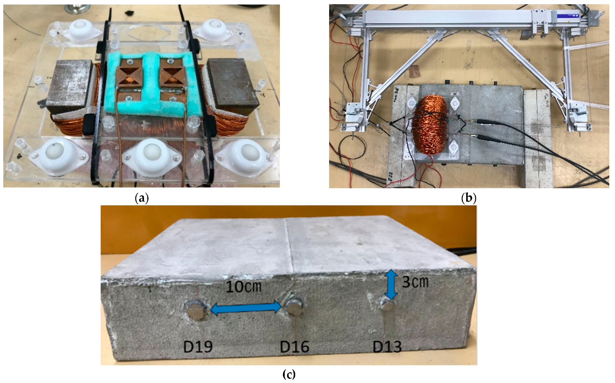
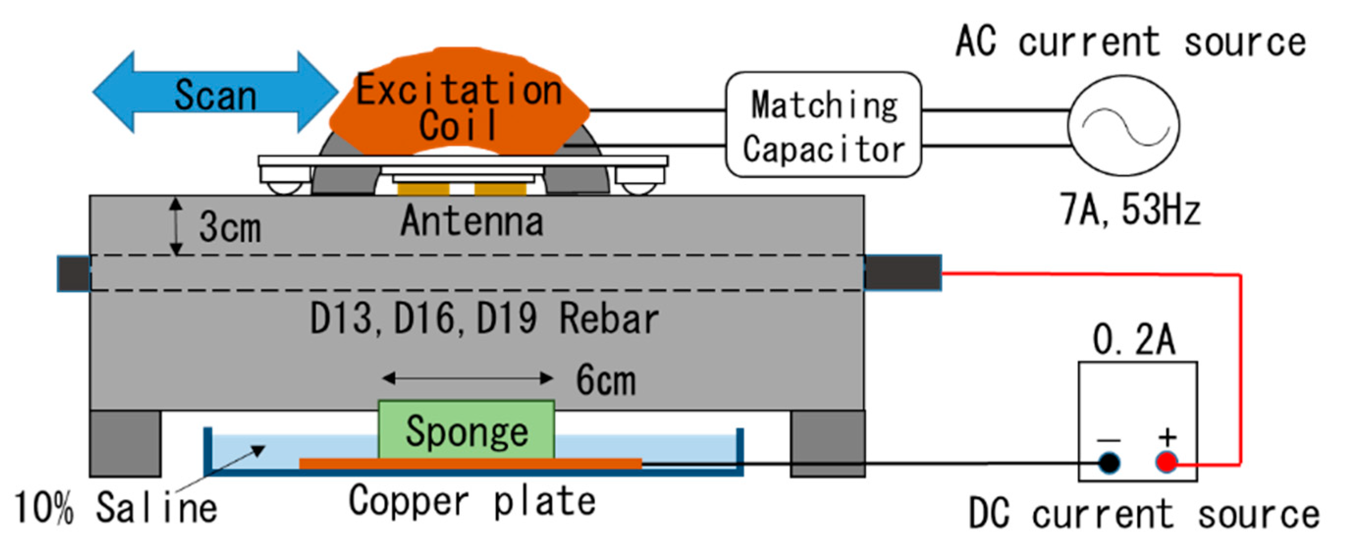
Hence, we first introduced an idea to GPR, which discusses the phase difference of a wave reflected from a rebar in concrete by selectively vibrating only the rebar with an excitation coil, where a vibro-Doppler radar (VDR) method [
37] has been proposed to measure the vibration displacement of rebar in concrete using the Doppler radar method. The rebar is sinusoidally vibrated by the excitation coil at about 50 Hz. Some nondestructive methods have been proposed to monitor the vibration response on the concrete surface by magnetic excitation to rebar with low single frequency [
7] and impulsive wave [
38]. However, our method has the advantage of obtaining the pure vibration information of the rebar in concrete because the vibrations obtained on the surface often suffer from inhomogeneity for elastic wave propagation. In addition, this method can acquire not only the conventional radar waveform (unmodulated component) but also a radar waveform sensitive only to vibrating objects (Doppler modulated component), and can quantitatively determine the vibration displacement of a single rebar from the amplitude ratio of reflected waves of both components. Monitoring of vibrational displacement of rebars during electrolytic corrosion testing on RC specimens showed that vibrational displacement increased even before surface cracks became apparent, and eventually vibration displacement reached approximately four times that of the healthy condition, suggesting that the VDR method may be sensitive to the vibration ability of adhered rebar in concrete.
A VDR system appears to be the only modality to quantitatively evaluate the vibration ability of rebar in concrete. However, the developed VDR system in the frequency domain using a network analyzer requires as much as 120 s to measure a single point. Even a scan measurement of 30 cm width at 5 mm intervals takes about two hours, which is a major practical problem. In addition, corrosion of rebar is expected to occur locally in the areas where penetration resistance of corrosion factor is low. Therefore, fixed or coarse spacing measurements with a conventional system can often fail to detect an increase in vibration displacement.
If a high-speed VDR system can be developed, a parallel scan of a rebar with VDR gives vibration displacement spatially distributed on the rebar in practical time. Electrolytic corrosion tests are often used to accelerate the corrosion of rebar in RC specimens. After the test, the RC specimen is destroyed and the rebar is removed, often showing spatially localized corrosion. If the relationship between local vibration displacement obtained by VDR and localized rebar corrosion in concrete can be clarified, early detection and repair of corrosion can be more effectively carried out. The distribution of vibration displacement of rebar as well as the spatial variation due to the progress of corrosion are very interesting and essential.
Thus, in this paper, a pulse radar-based VDR system is developed and scanning measurements of RC concrete specimens are performed to evaluate the performance of image-based vibration displacement of rebar. Furthermore, the feasibility of non-destructive evaluation of localized rebar corrosion is verified by monitoring vibration displacements spatially distributed on a rebar undergoing corrosion using an electrolytic corrosion test.
2. Principle of Waveform-Based Vibration Displacement Measurement
The detection of moving objects by Doppler radar is a fundamental technique that takes advantage of the fact that the frequency of the wave reflected from a moving object is shifted as proportional to the velocity of the object. Many recent applications, such as vital sign measurements [
39,
40] and through-wall radar [
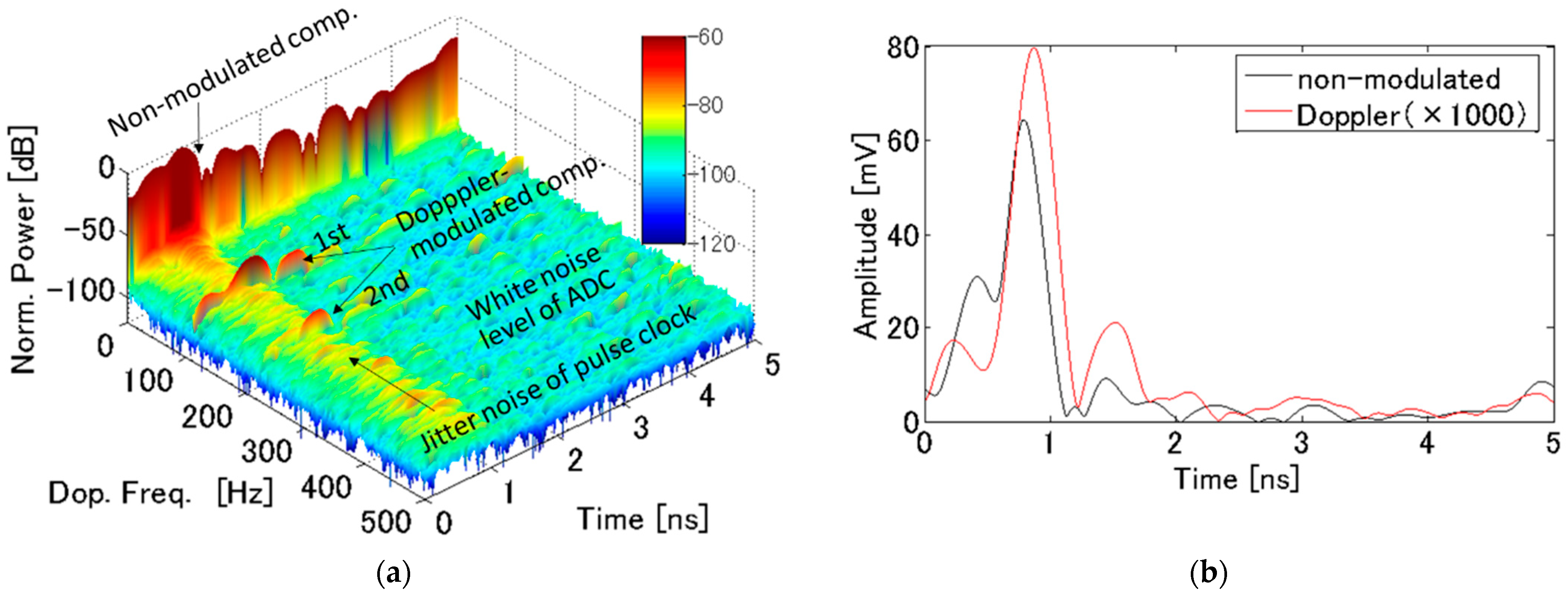
41], focus on how the target moves; FMCW systems are widely used in the millimeter wave band with wavelengths below the vibration displacement of the target. On the other hand, if the target is sinusoidally vibrating, the frequency spectrum of the reflected wave is separated by phase modulation into multiple line spectra (called as the
th Doppler modulation component) of the vibration frequency interval. If the magnitude of the vibration is much smaller than the wavelength, the amplitude of the nth Doppler component is known to be proportional to the factorial of
. Here, the magnitude of the vibration of the rebar in the VDR measurement is about 1/1000 of the wavelength in concrete. Therefore, the measurement system in VDR requires quite a higher dynamic range than that used in other applications.
Figure 1 shows a conceptual diagram of displacement measurement using VDR based on a pulse radar. As a pulse waveform, consider a complex modulated pulse wave
, in which an arbitrary unimodal solitary wave
with peak value 1 at
is modulated by a complex sine wave with center frequency
as:
Now, the pulse wave is emitted toward a reflector at a distance
from an antenna, and the reflected wave from the reflector is received with the same antenna. The received complex radar waveform
is expressed as in Equation (2), where the reflection coefficient is
and the propagation velocity of the electromagnetic wave is
.
In this case, the real part of
corresponds to the conventional radar waveform and the imaginary part to the Hilbert transform of the real part. Furthermore, when the reflector is vibrated in the direction of propagation of the electromagnetic wave with a frequency
and vibration amplitude
, the propagation distance of the reflected wave changes due to the vibration, and the time variation is expressed as
as:
As the time variation of the radar waveform is on the order of GHz, while
is several tens Hz, which is equivalent to
being stationary with respect to the radar waveform variation. Since the repetition period of acquisition time
of the radar waveform is on the order of kHz, the delay time
of the radar waveform and its acquisition time
can be regarded as independent. The 2D complex radar signal
, which is the radar waveforms sorted by repetition, can be expressed as:
Let
and
be the Fourier transformation of
and
with respect to the delay time
t, respectively, the Fourier transformation of
with respect to
is expressed as in Equation (5).
Furthermore, the wavelength of the electromagnetic wave
is on the order of cm, while the vibrational displacement
is extremely small, on the order of μm. Therefore,
, a first order approximation of Equation (5) yields Equation (6).
Here,
is separated into a term with and without variation in the acquisition time
. If we take a Fourier component of
with respect to
at the vibration frequency of
, the Doppler component
by forced vibration is expressed as positive Doppler component in Equation (7).
Here, the unmodulated component corresponds to the Doppler component at 0 Hz, which is equivalent to the conventional radar signal with no vibration.
Furthermore, by inverse Fourier transforming
and
with respect to the frequency
, complex radar waveforms
and
of unmodulated and Doppler modulated components are obtained as follows, respectively.
Therefore, the vibration displacement
of the vibrating reflector at distance
can be expressed as in Equation (10) using the time derivative waveform of the unmodulated component and the Doppler component waveform.
Figure 2 shows the flow of the vibration displacement measurement. The measured radar signal
is transformed into a complex radar signal
by adding the Hilbert transform of
into the imaginary part as an analytical function. Then, the Doppler spectrum
is obtained by Fourier transforming
with respect to
. By letting
= 0 and
in
, an unmodulated waveform
and a Doppler modulated waveform
can be extracted, respectively. The vibration displacement of the reflector can be obtained by taking the amplitude ratio at the corresponding delay time to the distance
in the Doppler waveform and in the time derivative of the unmodulated waveform, as in Equation (10).
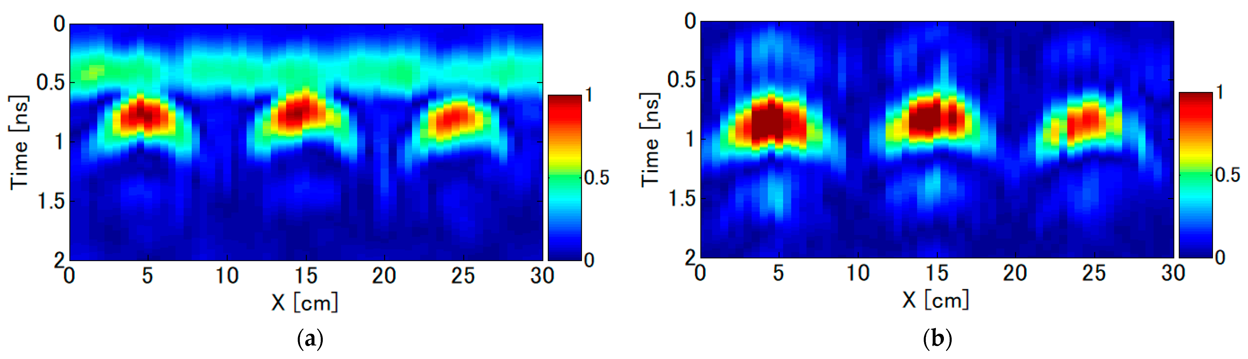
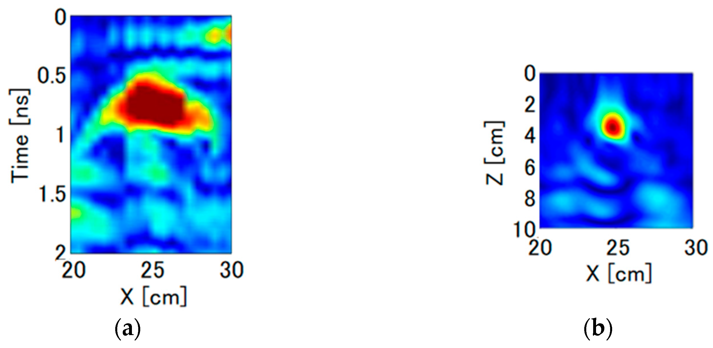
3. Principle of Imaging-Based Vibration Displacement Measurement
In general, when a radar scans directly above an isolated object and acquires radar profiles at certain intervals, the arrival time of the reflected waves in the radar profile is known to be parabolic. This results in poor spatial resolution in the scan direction. In such cases, the synthetic aperture method is widely used to improve the horizontal resolution. In this paper, we use the Kirchhoff transfer method, in which the radar waveform obtained in the time domain is time-shifted and superimposed on the image domain. The distance
between the
th antenna position
and a virtual reflection point
is expressed as in Equation (11).
If the speed of light is
and the relative permittivity of the medium is
, the propagation velocity is
. If the received waveform obtained at the antenna position
is
, the amplitude of the wave arriving at each antenna position from the virtual reflection point can be expressed as
. Therefore, the evaluation function at the virtual reflection point is calculated by adding
at all antenna positions. The spatial distribution of the evaluation function has its maximum value at the true reflection point. On the other hand, the value of the evaluation function decreases at other points because the phases of
is added randomly. Therefore, the evaluation functions
and
corresponding to the unmodulated and Doppler modulated components are expressed as Equations (12) and (13), respectively.
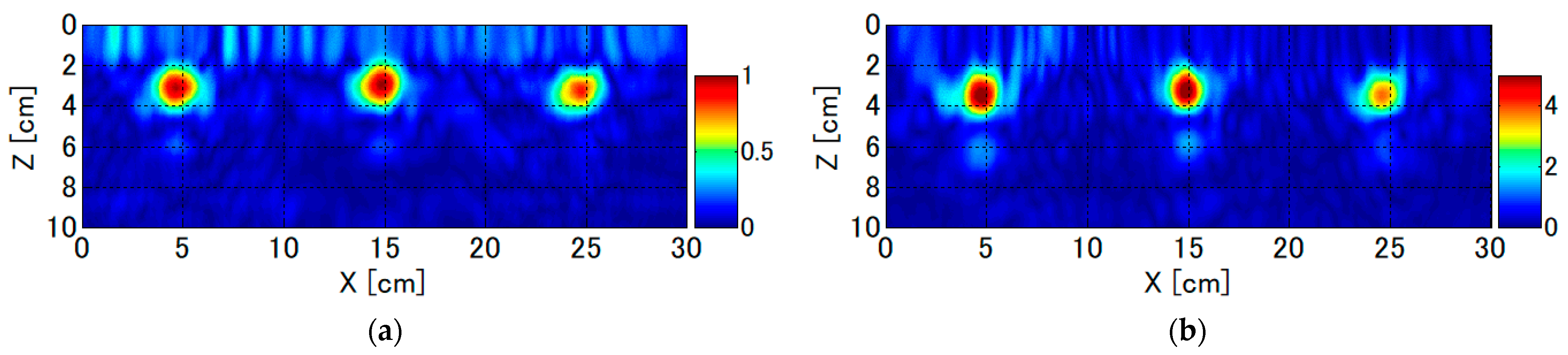
In general, the position
of the isolated object such as a rebar in concrete can be easily estimated by searching for a peak position of
or
. From Equation (10), the vibration displacement
of the rebar at the position
can be obtained using Equation (14).
This is an imaging based-algorithm for estimating the distribution of vibrational displacement of a rebar.
6. Discussion
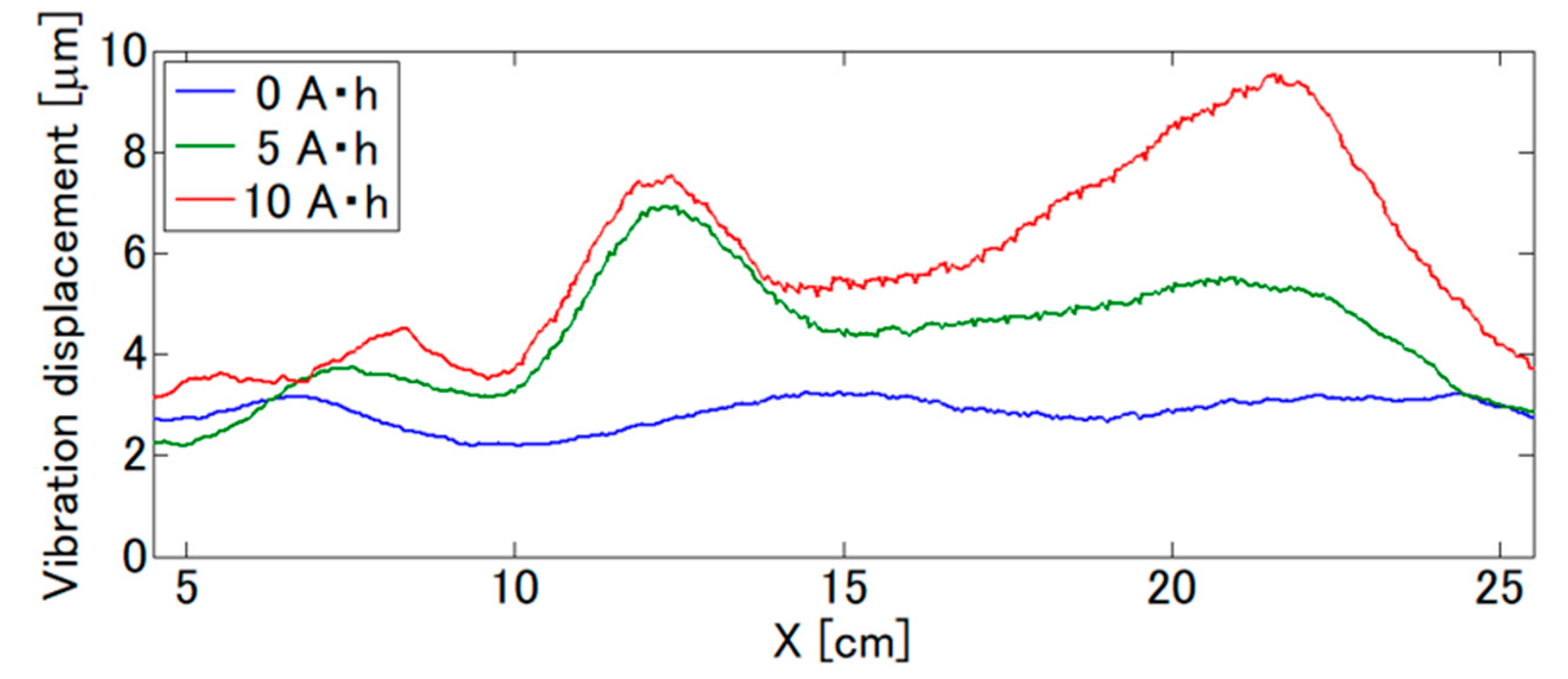
The saline solution was introduced from 12 to 18 cm, and the vibration displacement generally increased near this region, but not to a maximum at the central area = 15 cm. This may be due to the fact that oxygen is necessary for rebar corrosion in addition to chloride ions and water. Therefore, it is considered that the displacement increased outside of the central area where the oxygen penetration and the chloride ion concentration are high.
Moreover, a local increase in vibration displacement was observed in all specimens, and their locations coincided well with those of the rebar with localized corrosion loss. This indicates that the increase in local vibration displacement in the VDR system may be able to evaluate localized corrosion of the rebar. Its spatial resolution depends on the spatial resolution of the radar image, and
Figure 8 also shows that it is about 1 cm. The spatial resolution of the surface potential measurement [
9], which is practically used in existing corrosion evaluation methods, is several tens of centimeters or more, and the proposed VDR system is considered possible to evaluate local rebar corrosion with a high spatial resolution.
In addition, it has been clarified that there is a certain degree of correlation between the vibration displacement and the amount of corrosion. However, quantitative discussion is difficult because the mechanisms of the increase in vibration displacement due to corrosion are not clarified. Here, related to the mechanisms, this experiment revealed that the width where the vibration displacement locally increased was on the order of a few centimeters. From
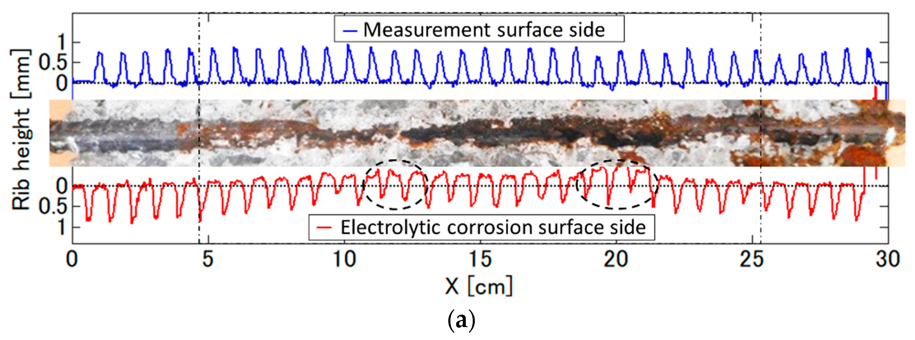
Figure 12, the maximum loss in the rib height under this corrosion condition is about 0.5 mm, which corresponds to a 2.6 to 3.8% reduction of the rebar diameter. So, the local increase in rebar vibration displacement obtained in the VDR method may reflect the local change in not mechanical but electromagnetic properties of a rebar due to corrosion.
In
Figure 12, a large amount of black rust deposition due to electrolytic corrosion was observed in the center of the rebar. The magnitude of the Doppler component is determined by the product of the amplitude of the unmodulated component (reflection coefficient) and the magnitude of the vibration displacement. In general, black rust in rust juice is considered to be more sensitive to the magnetic field than solid rebar. Since a VDR image does not clearly resolve rebar and black rust, both are measured as a single reflected wave. Thus, the Doppler component of the rebar with localized black rust may increase locally. The exact distribution of black rust around the rebar is not known in this measurement, and further investigation of the relationship between black rust distribution and locally increased vibration displacement of the rebar may allow for a more quantitative evaluation of rebar corrosion.
7. Conclusions
In this paper, a vibro-Doppler radar (VDR) system using an impulse radar has been developed to overcome the time-consuming problem of conventional VDR systems using network analyzers. The developed VDR achieved a dynamic range of 90 dB with a measurement time of 1 s, which is 120 times faster than conventional systems. We also proposed a method for estimating vibration displacement by image processing: VDR images have a spatial resolution of 1 cm, which provides vibration displacement of a spatially distributed target. The VDR system was scanned parallel to the rebar, and the distribution of vibration displacement of the rebar was successfully evaluated.
Through an electrolytic corrosion test, changes in the vibration displacement distribution due to corrosion were monitored simultaneously. After the electrolytic corrosion test, the rib heights obtained from the laser displacement meter were investigated, and the results showed that the rebar tended to decrease in height by a maximum of 0.5 mm under the corrosion conditions, but the location of the strongest decrease appeared to be localized off center, although the nodal height in the middle of the rebar tended to decrease.
The distribution of vibration displacement during the electrolytic corrosion test showed that vibration displacement tended to increase with corrosion for all specimens, and the vibration displacement was locally increased several times. The width where the vibration displacement locally increases was found to be as narrow as a few centimeters. The localized position of vibration displacement and the localized position of rebar corrosion loss were generally in agreement with each other.
Therefore, it is demonstrated that the proposed VDR system can detect corrosion localized in a width of several centimeters on a rebar by the spatial distribution of the vibration displacement. Because of the localization of corrosion, VDR measurement should be performed while scanning, rather than being fixed.
In the future, we plan to develop a system that can evaluate the spatial distribution of deterioration of large specimens, which has been difficult in the past, from vibration displacement imaging by scanning type measurement, which has many measurement points, by taking advantage of the merits of shorter measurement time and higher accuracy.


