Technical Note

A Method of Whole-Network Adjustment for Clock Offset Based on Satellite-Ground and Inter-Satellite Link Observations

1
Aerospace Information Research Institute, Chinese Academy of Sciences, Beijing 100094, China
2
Beijing Satellite Navigation Center, Beijing 100094, China
3
Shanghai Astronomical Observatory, Chinese Academy of Sciences, Shanghai 200030, China
*
Author to whom correspondence should be addressed.
Remote Sens. 2022, 14(20), 5073; https://doi.org/10.3390/rs14205073
Submission received: 11 August 2022 / Revised: 1 October 2022 / Accepted: 6 October 2022 / Published: 11 October 2022
(This article belongs to the Special Issue Space-Geodetic Techniques)

Abstract

:
The inter-satellite link is an important technology to improve the accuracy of clock offset measurement and prediction for BeiDou Navigation Satellite System (BDS). At present, BDS measures clock offsets of invisible satellite mainly through the “one-hop” reduction mode based on the satellite-ground clock offset of the node visible satellite and the inter-satellite clock offset between the two satellites. However, there exists a systematic deviation caused by the node satellite reduction, and there is still a large room for improvement in clock offset measurement and prediction. Therefore, this paper firstly proposes a method of whole-network adjustment for clock offset based on the satellite-ground and inter-satellite two-way data. The least square method is used to realize the whole-network adjustment of clock offset based on the observations of two sources, and to obtain optimal estimates of different clock offset reduction. Secondly, the evaluation method combining internal and external symbols are proposed by the fitting residual, prediction error and clock offset closure error. Finally, experimental verification is completed based on BDS measured data. In comparison with the “one-hop” reduction method, the fitting residual and prediction error of the whole-network adjustment method reduces about 45.06% and 52.15%, respectively. In addition, inter-satellite station closure error and three-satellite closure error are reduced from 0.69 ns and 0.23 ns to about 0 ns. It can be seen that the accuracy of BDS time synchronization is significantly improved.

1. Introduction

The inter-satellite link (ISL) is not only an important feature and technological innovation of BDS, but also an important means to optimize the distribution of regional station, improve the accuracy of spatial signals and increase the frequency of message injection [1,2,3]. BDS-3 has provided the global services officially on 31 July 2020, and all of the satellites are equipped with ISL [4]. Based on the Time Division Multiple Access (TDMA) technique and the Ka-band technology of BDS ISL strategy, any visible satellites can achieve real-time inter-satellite measurement and communication by the multipoint-to-multipoint time-division two-way links [5,6].
In contrast with GPS and GALILEO systems that update ephemeris and clock offset parameters mainly through the global uniform distribution of stations [7,8], BDS adopts the combined time synchronization strategy which determines satellite clock offset parameters by the satellite-ground link (SGL) for visible satellite and inter-satellite link (ISL) for invisible satellite [9,10]. This strategy was first published in 2018, and usually called as the “one-hop” reduction method [11]. According to this method, when the satellite is visible by the Master Control Center (MCC), the clock offset is measured through the SGL L-band satellite-ground two-way time synchronization; when the satellite is invisible by MCC, the clock offset is calculated by one node satellite (which is visible to both MCC and the invisible node satellite) of the SGL L-band two-way time synchronization and these two satellites of the ISL Ka-band two-way time synchronization, thus clock offsets of invisible satellite can be calculated through the “one-hop” reduction mode by one node visible satellite [11,12]. Compared with only SGL, the tracking coverage is extended by 40% by using ISL [11], the prediction error can be reduced from 3 ns to 1 ns [13], and the orbit result is also greatly improved [14,15,16].
Some achievements have been published to estimate the affections of the systematic error. Yan [17] and Wang [18] estimate the satellite antenna phase center offsets (PCOs), phase variations (PVs) and the differential code bias (DCB) of BeiDou-3 satellites, and has the results that PCOs and PVs is different with satellites, and DCB value is related to the receiver type. Moreover, Liu [19] proposes a network adjustment model by the correction of inter-satellite clock offsets to detect and analyze the closed residuals, and has the results that the random noise of the inter-satellite clock corrections is reduced by 30% to 50%. These achievements have evaluated the performance of current system and given the application conclusions that the signal in space accuracy has reached up to 0.5 m [2]. However, systematic errors of the measured SGL clock offsets and the calculated ISL clock offsets using different node satellite exist, which affect the accuracy of the time synchronization [12,20].
This paper further studies the whole-network adjustment method by multi-source clock offset of the satellite-ground and inter-satellite observation. Taking SGL and ISL data of all orbiting satellites as a whole, this new method is used to realize the satellite-ground and inter-satellite time synchronization in the entire constellation. The propose is to optimize the time synchronization strategy of BDS, minimize the impact of different devices, and improve the accuracy of BDS broadcast clock offset.

2. Materials and Methods

2.1. Time Synchronization Principle

2.1.1. L-Band Satellite-Ground Two-Way Time Synchronization

BDS achieves satellite-ground time synchronization using L-band two-way time comparison. The satellite and ground station, respectively, generate and broadcast pseudocode ranging signals based on the control of local clocks. Specifically, the ground station obtains the downlink pseudorange at the time corresponding to the ground 1 pulse per second (pps), and the satellite obtains the uplink pseudorange at the time corresponding to the satellite 1 pps. Meanwhile, the satellite sends the observed value of uplink pseudorange to the ground station, and then the ground station calculates the difference between the locally measured downlink pseudorange and the received uplink pseudorange to obtain the clock offset of satellite relative to the ground station. It lays a foundation for completing the satellite-ground two-way time comparison. The principle of L-band satellite-ground two-way time comparison is shown in Figure 1.
The satellite-ground two-way time comparison method is used to obtain the observed satellite-ground clock offset, which can be expressed by a second-order polynomial:
Δ T s Δ T g = 1 2 c ( ρ u ρ d ) 1 2 c ( R u R d ) τ r e l + ε
where Δ T s , Δ T g , respectively, denote the satellite clock offset and the ground station clock offset; ρ u , ρ d represent the uplink and downlink pseudorange, respectively; R u , R d indicate the theoretical values of uplink and downlink geometric distances, respectively; τ r e l represents the relativistic effect delay in the signal propagation path; ε indicates the synthetic measurement noise of the satellite-ground two-way link; and c represents the velocity of light.
The satellite-ground two-way time comparison method is used to obtain the observed value of satellite-ground clock offset. The satellite-ground clock offset of satellite i can be expressed by a second-order polynomial [21]:
Δ T i ( t ) = a 0 i + a 1 i ( t t 0 ) + a 2 i ( t t 0 ) 2
where Δ T i ( t ) represents the discrete point of satellite-ground clock offset of satellite i; t denotes the observation time of satellite-ground clock offset; t 0 refers to the reference time of clock offset parameter; a 0 i , a 1 i , a 2 i represent the clock offset, clock rate, and clock drift, respectively.

2.1.2. Ka-Band Inter-Satellite Two-Way Time Synchronization

It is similar to the satellite-ground two-way time comparison method. If satellite i and satellite j send time signals to each other at the clock T i and T j , the signal sent by satellite i is received by satellite j after the delay from satellite i to satellite j. On this basis, the pseudorange from satellite i to satellite j can be measured. Similarly, the signal sent by satellite j is received by satellite i after the delay from satellite j to satellite i, so that the pseudorange from satellite j to satellite i can be measured. Next, satellite i and satellite j exchange their respective observation results, and finally calculate the relative clock offset between them. The detailed principle of Ka-band inter-satellite two-way time comparison is shown in Figure 2.
Similar with the satellite-ground two-way time synchronization, the inter-satellite time synchronization of navigation satellites is based on pseudorange measurement of Ka-band two-way time synchronization, and the inter-satellite clock offset can be obtained as:
Δ T j Δ T i = 1 2 c ( ρ i j ρ j i ) 1 2 c ( R i j R j i ) + δ
where Δ T i , Δ T j represent the clock offsets of satellite i and satellite j, respectively; ρ i j refers to the pseudorange of satellite j receiving from satellite i; ρ j i refers to the pseudorange of satellite i receiving from satellite j; R i j , R j i respectively, represent the theoretical values of two-way geometric distances; δ indicates the synthetic measurement noise of the inter-satellite two-way link; and c represents the velocity of light.
The inter-satellite two-way time comparison method is used to obtain the observed inter-satellite clock offset, which can be expressed by a second-order polynomial [21]:
Δ T i j ( t ) + v i j = a 0 j + a 1 j ( t t 0 ) + a 2 i ( t t 0 ) 2 ( a 0 i + a 1 i ( t t 0 ) + a 2 i ( t t 0 ) 2 )
where Δ T i j ( t ) represents the discrete point of inter-satellite clock offset of satellite j relative to satellite i; t denotes the observation time of inter-satellite clock offset; t 0 refers to the reference time of clock offset parameter; v i j indicates the Ka-band inter-satellite link delay calibrated based on the L-band satellite-ground link; a 0 i , a 1 i , a 2 i represent the clock offset, clock rate and clock drift, respectively.

2.2. Whole-Network Adjustment Method

The Whole-network adjustment method uses multi-source clock offset data to obtain the clock offset parameters of satellite-ground and inter-satellite of all satellites. Assuming there is m satellites and n inter-satellite links, the m satellite-ground clock offsets and n inter-satellite clock offsets can be performed by whole-network adjustment method, and the equation can be abbreviated as:
L = C x v
where L = ( Δ T i ( t ) Δ T i j ( t ) ) ( m + n ) 1 represents the discrete point of m satellite-ground and n inter-satellite clock offset; C = [ C i C i j ] ( m + n ) * 3 m refers to the coefficient matrix of observation time; x = ( x 1 x i x m ) 3 m 1 indicates the column vector of clock offset parameters; x i = ( a 0 i a 1 i a 2 i ) denotes the clock offset parameter of each satellite; v = ( 0 v i j ) ( m + n ) 1 refers to the link delay error [22]. The coefficient matrix is expressed as follows:
C i = [ 1 t t 0 ( t t 0 ) 2 0 0 0 0 0 0 0 0 0 1 t t 0 ( t t 0 ) 2 0 0 0 0 0 0 0 0 0 1 t t 0 ( t t 0 ) 2 ] m × 3 m C i j = [ 0 1 ( t t 0 ) ( t t 0 ) 2 0 1 ( t t 0 ) ( t t 0 ) 2 0 0 1 ( t t 0 ) ( t t 0 ) 2 0 1 ( t t 0 ) ( t t 0 ) 2 0 0 1 ( t t 0 ) ( t t 0 ) 2 0 1 ( t t 0 ) ( t t 0 ) 2 0 ] n × 3 m
The principle of least squares is used to obtain the normal equation corresponding to the above equation:
C T P ( L + v ) = C T P C x
where P refers to the weight matrix of the observed column vector, and it can be assigned as the identity matrix when all satellites and atomic clocks are stable according to the classical least square method [23]. The normal equation is solved to obtain the clock offset parameter x of satellite-ground and inter-satellite multi-source data of all satellites.

2.3. Accuracy Evaluation Method

The accuracy evaluation of satellite clock offset is effective to verify the reliability of satellite clock offset data processing results. The optimal clock offset accuracy evaluation uses the theoretical real clock offset to evaluate the calculated clock offset accuracy. However, it is very difficult to obtain the theoretically real clock offset. The clock offset accuracy can be evaluated through different methods such as the inner coincidence accuracy comparison method and the outer coincidence accuracy comparison method. As for the internal coincidence accuracy comparison method, the accuracy is judged based on internal errors that generally refer to the fitting residual or prediction error of clock offset. According to the external coincidence accuracy comparison method, the accuracy is judged based on external information or other link information, which generally refers to the closure error of clock offset, mainly including the inter-satellite station closure error and three-satellite closure error.

2.3.1. Fitting Residual

The discrete points of clock offset are fitted to obtain the fitted clock offset, and the interval between discrete points is 1 s. The differences between the fitted clock offset and the actual clock offset is calculated to obtain the fitting residual of clock offset. The root mean square (RMS) is usually used to represent the fitting residual of clock offset, which can be obtained as follows:
σ = i = 1 n ( Δ T i C Δ T i O ) 2 n 1
where n represents the number of observation data, Δ T i C represents the calculated value of the ith fitted clock offset, and Δ T i O denotes the observed value of the ith actual clock offset. Generally speaking, the smaller RMS of the fitting residual indicates the better stability of clock offset, and the higher accuracy of time synchronization. it is noted that the actual clock offset is the post precision satellite clock offset [24].

2.3.2. Prediction Error

The time scale is set to improve the accuracy of satellite broadcast clock offset parameters, so as to ultimately serve users well. The clock offset parameter is calculated by the whole-network adjustment method and used for clock offset prediction. The difference between prediction result and actual clock offset is calculated to obtain the prediction error of clock offset.
Δ T e r r o r ( t ) = Δ T p r e d ( t ) Δ T a c t u a l ( t ) = a 0 + a 1 ( t t 0 ) + a 2 ( t t 0 ) 2 Δ T a c t u a l ( t )
where Δ T a c t u a l ( t ) refers to the actual clock offset, Δ T p r e d ( t ) denotes the predicted clock offset, and a 0 , a 1 , a 2 indicate the time difference, frequency difference and frequency drift, respectively, which are the clock offset parameters calculated through the whole-network adjustment.
The satellite clock offset prediction is divided into short-term prediction and long-term prediction. Specifically, first-order polynomial fitting is performed by 2-h clock offset data to predict 1-h result, and statistics the RMSs of 1-h prediction error. In contrast, second-order polynomial fitting is performed by 48-h clock offset data to predict 24-h result, and statistics the RMSs of 24-h prediction error. This paper adopts the short-term prediction method for evaluation.

2.3.3. Closure Error

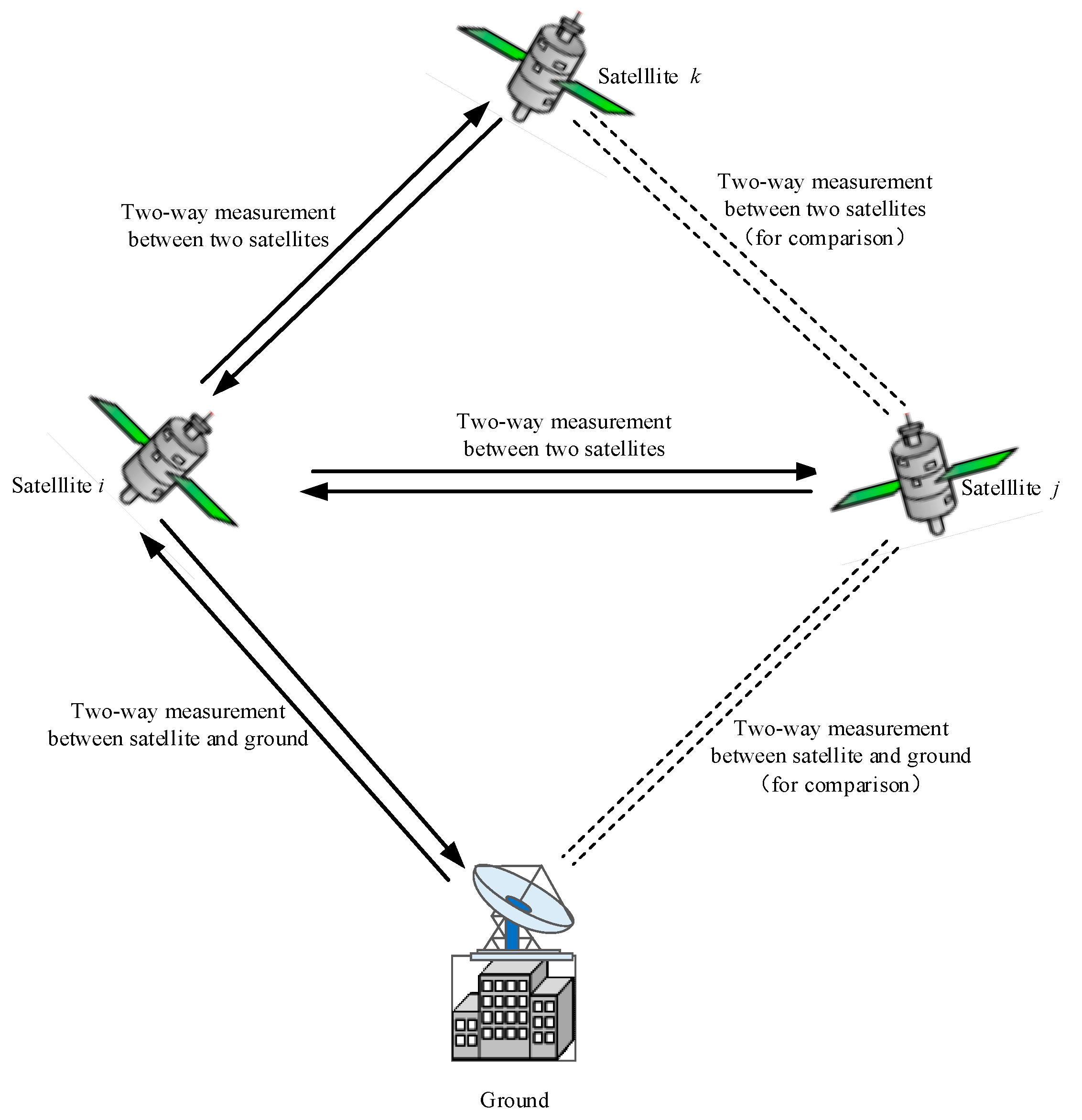
In order to further verify the effectiveness of the whole-network adjustment method, time synchronization performance is tested according to the closure errors of clock offset. The commonly used closure errors of clock offset include the inter-satellite station closure error and three-satellite closure error. The inter-satellite station closure error is shown in Figure 3.
Supposing the satellite i is the node satellite, the clock offset of satellite j can be observed indirectly. If there exist the two-way clock offset Δ T i between satellite i and ground station, and Δ T i j between satellite i and satellite j in the same time period, the clock offset of satellite j can be obtained as:
Δ T j = Δ T i j + Δ T i
The difference between Δ T j and satellite-ground two-way time synchronization observed value Δ T j of satellite j is calculated to obtain the residual of the indirect clock offset. Since it is difficult to find the observed values of Δ T i , Δ T i j and Δ T j in the same time period, one day of data are acquired. Δ T i and Δ T i j are fitted to obtain the indirect fitting parameter of Δ T j and then calculate the fitting residual of Δ T j within the direct observation period.

3. Results

3.1. Data Situation

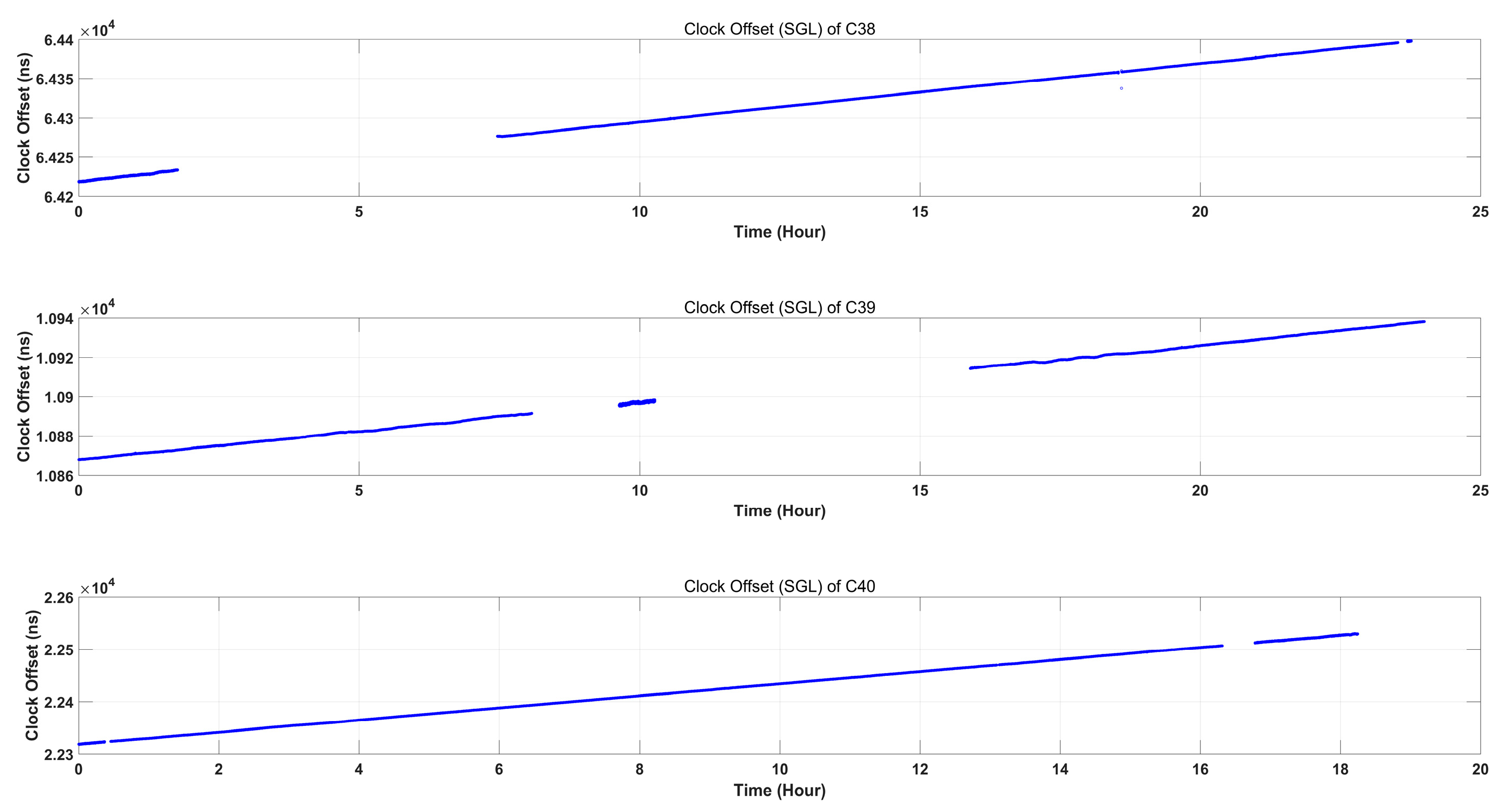
In order to obtain comprehensive and sufficient calculation results, this paper calculates the whole-network adjustment results of multi-source data according to the L-band satellite-ground two-way time synchronization and Ka-band inter-satellite two-way time synchronization of BDS on 1 March 2022. In addition, this paper makes a comparative analysis of “one-hop” reduction results for the same period. It is worth noting that GEO satellites mainly deliver SBAS, RDSS and other services, so they are without involvement in inter-satellite calculations. Therefore, this paper selects the data of 24 MEO satellites and 3 IGSO satellites for calculation. The data of all the 27 satellites are used for the inter-satellite calculation. The satellite-ground clock offset curve is shown in Figure 4, and ISL establishment during this period is shown in Figure 5.
As shown in Figure 4, the satellite-ground clock offset curve changes steadily, and we can see from Figure 5 that satellite C38 and other 26 satellites all have established links. Based on such data, we verify the validity of the whole-network adjustment method.

3.2. Fitting Residual

The fitting residuals are calculated based on the clock offset time series. Taking satellites C35, C36 and C37 as example, the fitting residuals using “one-hop” reduction method and the whole-network adjustment method are shown in Figure 6.
As shown in Figure 6, the fitting residuals of “one-hop” reduction method are fluctuating between ±3.5 ns, and the RMSs of fitting residuals of satellites C35, C36 and C37 are 0.25 ns, 0.37 ns, and 0.38 ns, respectively. The fitting residuals of the whole-network adjustment method are fluctuating between ±1 ns, and the RMSs of fitting residuals of satellites C35, C36 and C37 are 0.10 ns, 0.14 ns, and 0.13 ns, respectively.
The RMSs of fitting residuals of all satellites are further calculated, which reflect the internal coincidence accuracy of fitting results. The RMS statistical results of clock offset fitting residuals of 27 satellites are detailed in Table 1.
As shown in Table 1, the RMSs of clock offset fitting residuals of all satellites subject to “one-hop” reduction method between 0.19 ns and 0.42 ns, with a mean of 0.32 ns. The RMSs of clock offset fitting residuals of all satellites subject to whole-network adjustment range between 0.10 ns and 0.19 ns, with a mean of 0.13 ns. Compared with the “one-hop” reduction, whole-network adjustment improves the clock offset fitting residual accuracy by nearly 45.06%.
It is noted that the improvement rate differs widely, the reason is that the value of all satellites subject to “one-hop” reduction method differs widely, and the value subject to the whole-network adjustment method is relatively small and close. This result further proves that the whole network adjustment method eliminates the equipment errors of different satellites.

3.3. Prediction Error

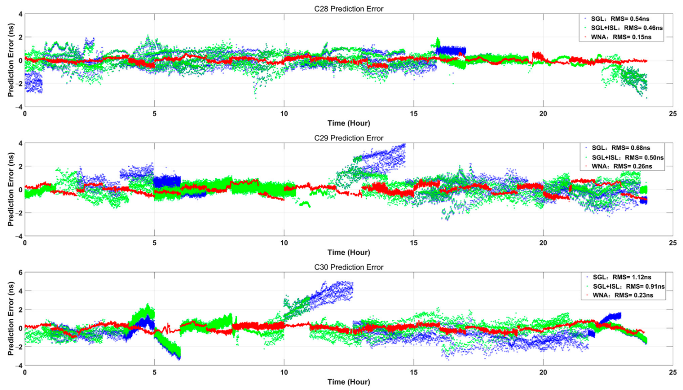
In order to further analyze the effectiveness of whole-network adjustment, the 2-h clock offset data are used for slip prediction in the next one hour. The slip prediction result is compared with the actual observation value to obtain the prediction error. In order to better analyze the effectiveness of different methods, we also use only the satellite-ground data for comparison. Taking satellites C28, C29 and C30 as example, the clock offset prediction errors of only satellite-ground method, “one-hop” reduction method and the whole-network adjustment method are shown in Figure 7.
As shown in Figure 7, the prediction error of only satellite-ground is fluctuating between ±6 ns, and the RMSs of clock offset prediction errors of satellites C28, C29 and C30 are 0.54 ns, 0.68 ns and 1.12 ns, respectively. The clock offset prediction error of “one-hop” reduction method are fluctuating between ±4 ns, and the RMSs of clock offset prediction errors of satellites C28, C29 and C30 are 0.46 ns, 0.50 ns, and 0.91 ns, respectively. The clock offset prediction error of the whole-network adjustment method are fluctuating between ±1 ns, and the RMSs of clock offset prediction errors of satellites C28, C29 and C30 are 0.15 ns, 0.26 ns, 0.23 ns, respectively. The RMSs of clock offset prediction errors of all satellites are further calculated and the statistical results are shown in Table 2.
As shown in Table 2, the RMSs of predicted only satellite-ground method range between 0.33 ns and 1.66 ns, with a mean of 0.72 ns. The RMSs of predicted clock offset of “one-hop” reduction method range between 0.32 ns and 0.98 ns, with a mean of 0.54 ns. The RMSs of predicted clock offset of the whole-network adjustment method range between 0.15 ns and 0.43 ns, with a mean of 0.25 ns. Compared with the only satellite-ground method and “one-hop” reduction method, the prediction accuracy of the whole-network adjustment method improves about 62.13% and 52.15%, respectively.

3.4. Closure Error

Analyzing the data on 1 March 2022, it can be seen that there are 226 inter-satellite station closure errors and 1710 three-satellite closure errors concerning 27 satellites. Some inter-satellite station closure errors and three-satellite closure errors are detailed in Table 3, and statistical results of all closure errors are itemized in Table 4.
It can be seen from Table 3 and Table 4, among 226 inter-satellite station closure errors and 1710 three-satellite closure errors, the closure error of inter-satellite station and three-satellite of “one-hop” reduction method are 0.69 ns and 0.23 ns, respectively. In addition, the closure error of the whole-network adjustment method is 1.34 × 10⁻¹⁰ and 5.54 × 10⁻¹¹, respectively, which both approximate 0. The results show that the closure error of inter-satellite station is subject to SGL reduction, while the closure error of three-satellite is subject to ISL measurement only. Therefore, three-satellite closure error is superior to the inter-satellite closure error, indirectly indicating that the SGL measurement error is a limiting factor that improves in the system time synchronization accuracy.

4. Conclusions

Based on the L-band satellite-ground clock offset data and the Ka-band inter-satellite clock offset data, this paper provides a method of whole-network adjustment for clock offset. In addition, the fitting residual, prediction error and closure error are used to evaluate and verify the effectiveness of this new method. This new method makes the RMS of the clock offset fitting residual reach up to 0.13 ns, which is lower than that of “one-hop” reduction by about 45.06%. As well, the RMS of clock offset prediction error hits about 0.25 ns, which is lower than those of only satellite-ground and “one-hop” reduction by about 62.13% and 52.15%, respectively. In addition, the closure error of inter-satellite station and three-satellite are approximate 0, which is much lower than 0.69 ns and 0.23 ns for “one-hop” reduction. This paper enriches the satellite navigation time synchronization system, and can be applied to clock offset measurement, systematic difference calculation and so forth. Furthermore, it provides a theoretical basis for effectively resolving systematic deviations in satellite-ground links and inter-satellite links. Most importantly, it will ultimately contribute to an improvement in the overall performance of BDS in navigation, positioning and timing.

Author Contributions

Conceptualization, D.W. and J.P.; methodology, L.L.; software, R.G. and X.L.; validation, D.W. and R.G.; formal analysis, R.G. and H.Y.; resources, D.W. and C.T.; data curation, D.W. and R.G.; writing—original draft preparation, R.G. and D.W.; writing—review and editing, D.W.; funding acquisition, R.G. All authors have read and agreed to the published version of the manuscript.

Funding

This research was funded by the National Natural Science Foundation of China, grant number 41874043.

Data Availability Statement

The data sources are supported by Beijing Satellite Navigation Center.

Acknowledgments

Thanks for the data sources support of Beijing Satellite Navigation Center, and thanks for the fund support of the National Natural Science Foundation of China (No. 41874043).

Conflicts of Interest

The authors declare no conflict of interest.

References

  1. Tan, S.S. Innovative development and forecast of BeiDou system. Acta Geod. Cartogr. Sin. 2017, 46, 1284–1289. [Google Scholar]
  2. China Satellite Navigation Office. BeiDou Navigation Satellite System Open Service Performance Standard (Version 3.0). 2021. Available online: http://www.beidou.gov.cn/xt/gfxz/202105/P020210526216231136238.pdf (accessed on 10 August 2022).
  3. Yang, Y.X.; Gao, W.G.; Guo, S.R.; Mao, Y.; Yang, Y.F. Introduction to BeiDou-3 navigation satellite system. Navigation 2019, 66, 7–18. [Google Scholar] [CrossRef] [Green Version]
  4. Yang, Y.X.; Mao, Y.; Sun, B.J. Basic performance and future developments of BeiDou global navigation satellite system. Satell. Navig. 2020, 1, 1–8. [Google Scholar] [CrossRef] [Green Version]
  5. Ruan, R.G.; Jia, X.L.; Feng, L.P.; Zhu, J.; Hu, Y.Z.; Li, J.; Wei, Z. Orbit Determination and Time Synchronization for BDS-3 Satellites with Raw Inter-Satellite Link Ranging Observations. Satell. Navig. 2020, 1, 8. [Google Scholar] [CrossRef] [Green Version]
  6. Wang, D.X.; Xin, J.; Xue, F.; Guo, R.; Chen, J.P. Prospect and development of GNSS autonomous navigation based on inter-satellite link. J. Astronaut. 2016, 37, 1279–1288. [Google Scholar]
  7. Ananda, M.P.; Bernstein, H.; Cunningham, K.E.; Feess, W.A.; Stroud, E.G. Global positioning system (GPS) autonomous navigation. In Proceedings of the Position Location and Navigation Symposium, the 1990’s-A Decade of Excellence in the Navigation Sciences, Las Vegas, NV, USA, 20 March 1990; pp. 497–508. [Google Scholar]
  8. Avila-Rodriguez, J.A.; Wallner, S.; Hein, G.W.; Eissfeller, B. A vision on new frequencies, signals and concepts for future GNSS systems concepts for future GNSS systems. In Proceedings of the 20th International Technical Meeting of the Satellite Division of the Institute of Navigation, Fort Worth, TX, USA, 25–28 September 2007. [Google Scholar]
  9. Tang, G.F.; Yang, W.F.; Su, R.R.; Xia, A.M. Time Synchronization Method base on Combined Satellite-Ground and Inter-satellite Observation. Geomat. Inf. Sci. Wuhan Univ. 2018, 43, 183–187. [Google Scholar]
  10. Sun, L.Y.; Wang, Y.K.; Huang, W.D.; Yang, J.; Zhou, Y.F.; Yang, D.N. Inter-satellite Communication and Ranging Link Assignment for Navigation Satellite Systems. GPS Solut. 2018, 22, 38. [Google Scholar] [CrossRef]
  11. Pan, J.Y.; Hu, X.G.; Zhou, S.S.; Tang, C.P.; Guo, R.; Zhu, L.F.; Tang, G.F.; Hu, G.M. Time synchronization of new-generation BDS satellites using inter-satellite link measurements. Adv. Space Res. 2018, 61, 145–153. [Google Scholar] [CrossRef]
  12. Yang, Y.F.; Yang, Y.X.; Hu, X.G.; Tang, C.P.; Guo, R.; Zhou, S.S.; Xu, J.Y.; Pan, J.Y.; Su, M.D. BeiDou-3 broadcast clock estimation by integration of observations of regional tracking stations and inter-satellite links. GPS Solut. 2021, 25, 57. [Google Scholar] [CrossRef]
  13. Chen, J.P.; Hu, X.G.; Tang, C.P.; Zhou, S.S.; Guo, R.; Pan, J.Y.; Ran, L.; Zhu, L.F. Orbit determination and time synchronization for new-generation beidou satellites: Preliminary results. Sci. Sin. Phys. Mech. Astron. 2016, 46, 119502. [Google Scholar]
  14. Yang, Y.X.; Xu, Y.Y.; Li, J.L.; Yang, C. Progress and performance evaluation of BeiDou global navigation satellite system: Data analysis based on BDS-3 demonstration system. Sci. China Earth Sci. 2018, 61, 614–624. [Google Scholar] [CrossRef]
  15. Cai, H.L.; Meng, Y.N.; Geng, T.; Xie, X. Initial Results of Precise Orbit Determination Using Satellite-Ground and Inter-Satellite Link Observations for BDS-3 Satellites. Geomat. Inf. Sci. Wuhan Univ. 2020, 45, 1493–1500. [Google Scholar]
  16. Yang, Y.F.; Yang, Y.X.; Hu, X.G.; Chen, J.P.; Guo, R.; Tang, C.P.; Zhou, S.S.; Zhao, L.Q.; Xu, J.Y. Inter-Satellite Link Enhanced Orbit Determination for BeiDou-3. J. Navig. 2020, 73, 115–130. [Google Scholar] [CrossRef]
  17. Yan, X.Y.; Huang, G.W.; Zhang, Q.; Wang, L.; Qin, Z.; Xie, S. Estimation of the Antenna Phase Center Correction Model for the BeiDou-3 MEO Satellites. Remote Sens. 2019, 11, 2850. [Google Scholar] [CrossRef] [Green Version]
  18. Wang, Q.S.; Jin, S.G.; Yuan, L.L.; Hu, Y.J. Estimation and Analysis of BDS-3 Differential Code Biases from MGEX Observations. Remote Sens. 2019, 12, 68. [Google Scholar] [CrossRef]
  19. Liu, C.; Gao, W.G.; Pan, J.Y.; Tang, C.P.; Hu, X.G.; Wang, W.; Chen, Y.; Lu, J.; Su, C.C. Inter-satellite clock offsets adjustment based on closed-loop residual detection of BDS inter-satellite link. Acta Geod. Cartogr. Sin. 2020, 49, 1149–1157. [Google Scholar]
  20. Guo, Y.; Gao, S.; Bai, Y.; Pan, Z.; Liu, Y.; Lu, X.; Zhang, S. A New Space-to-Ground Microwave-Based Two-Way Time Synchronization Method for Next-Generation Space Atomic Clocks. Remote Sens. 2022, 14, 528. [Google Scholar] [CrossRef]
  21. Huang, G.; Zhang, Q.; Xu, G. Real-time clock offset prediction with an improved model. GPS Solut. 2014, 18, 95–104. [Google Scholar] [CrossRef]
  22. Pan, J.Y.; Hu, X.G.; Tang, C.P. System error calibration for time division multiple access inter-satellite payload of new-generation Beidou satellites. Chin. Sci. Bull. 2017, 62, 2671–2679. [Google Scholar] [CrossRef] [Green Version]
  23. Bates, J.M.; Granger, C.W. The Combination of forecasts. Oper. Res. Soc. 1969, 20, 451–468. [Google Scholar] [CrossRef]
  24. Liu, L.; Zhu, L.F.; Han, C.H.; Liu, X.P.; Li, C. The model of radio two-way time comparison between satellite and station and experimental analysis. Chin. Astron. Astrophys. 2009, 33, 431–439. [Google Scholar] [CrossRef]
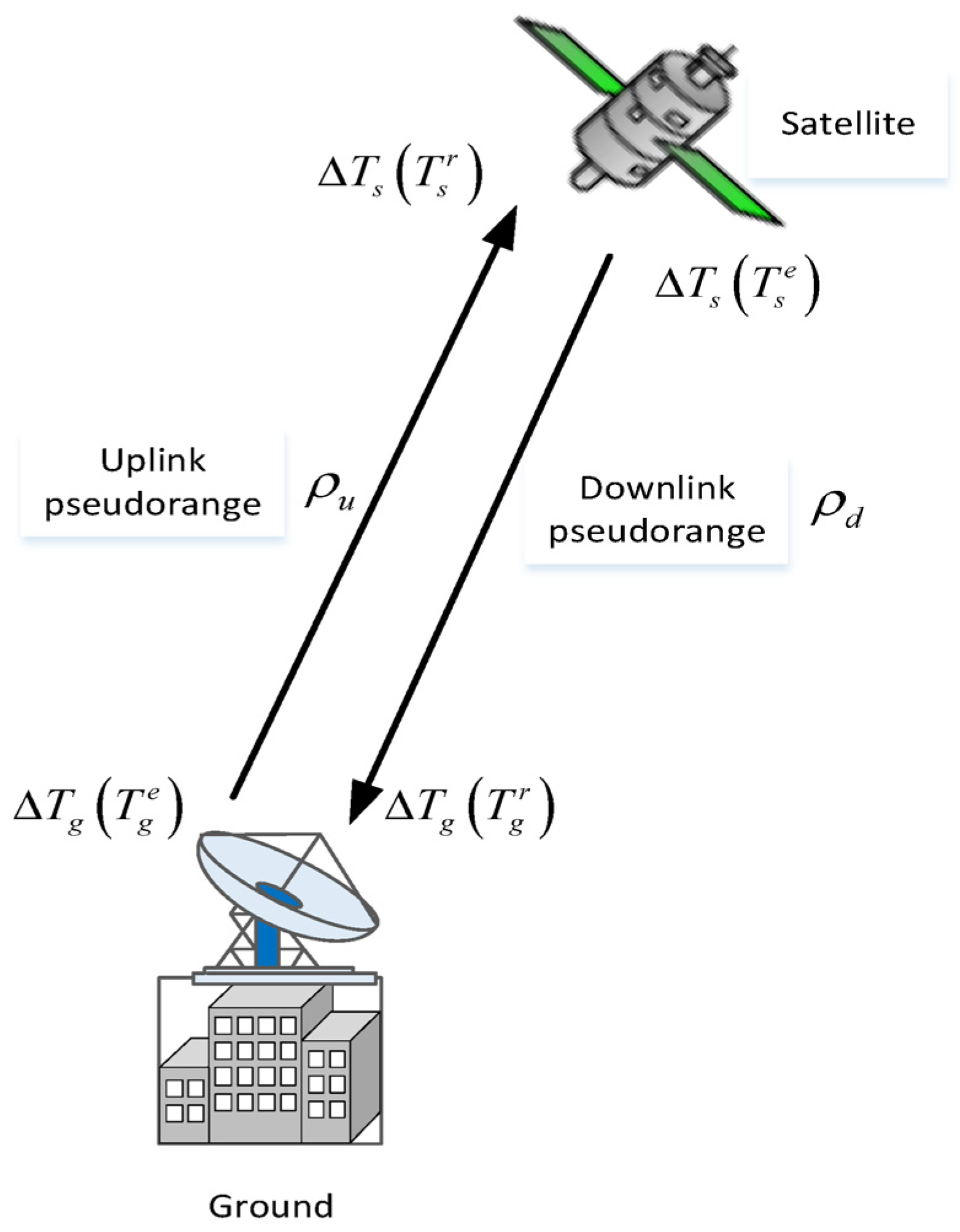
Figure 1. Schematic diagram of satellite-ground time synchronization.
Remotesensing 14 05073 g001
Figure 2. Schematic diagram of inter-satellite time synchronization.
Remotesensing 14 05073 g002
Figure 3. Schematic diagram of inter-satellite station closure error.
Remotesensing 14 05073 g003
Figure 4. Curve of SGL clock offset.
Remotesensing 14 05073 g004
Figure 5. ISL between C38 and other satellites.
Remotesensing 14 05073 g005
Figure 6. Clock residuals.
Remotesensing 14 05073 g006
Figure 7. Prediction error.
Remotesensing 14 05073 g007
Table 1. RMS statistical results of fitting residuals (unit: ns).
SatelliteSGL+ISL MethodWNA MethodImprovement Rate
C380.210.1319.05%
C390.200.1219.05%
C400.190.1216.67%
C250.340.1350.00%
C260.260.1330.95%
C270.340.1350.00%
C280.340.1252.38%
C290.350.1352.38%
C300.380.1554.76%
C190.320.1247.62%
C200.410.1171.43%
C210.280.1042.86%
C220.310.1440.48%
C230.390.1557.14%
C240.280.1238.10%
C320.360.1354.76%
C330.420.1954.76%
C340.310.1245.24%
C350.250.1035.71%
C360.370.1454.76%
C370.380.1261.90%
C410.320.1052.38%
C420.220.1028.57%
C430.320.1345.24%
C440.410.1757.14%
C450.290.1338.10%
C460.290.1045.24%
Mean 0.320.1345.06%
Table 2. RMS statistical results of prediction error (unit: ns).
SatelliteOnly SGL MethodSGL+ISL MethodWNA MethodImprovement Rate 1
(WNA Relative to Only SGL)
Improvement Rate 2
(WNA Relative to SGL+ISL)
C380.600.490.2951.67%40.82%
C390.400.400.2830.00%30.00%
C400.480.430.1960.42%55.92%
C250.670.510.2759.70%47.06%
C260.480.370.2743.75%27.03%
C270.770.570.2468.83%57.89%
C280.540.460.1572.22%67.39%
C290.680.500.2661.76%48%
C301.120.910.2379.46%74.73%
C190.800.680.2371.25%66.18%
C200.600.480.2263.33%54.17%
C210.590.510.2655.93%49.02%
C220.680.480.2957.35%39.58%
C230.870.630.3362.07%47.62%
C240.500.490.2354.00%53.10%
C320.760.650.2863.16%56.86%
C330.840.960.3459.52%64.64%
C341.250.490.2084.00%59.18%
C350.330.320.1942.42%40.63%
C360.660.730.2660.61%64.38%
C370.910.510.2275.82%56.86%
C410.490.420.2059.18%52.38%
C420.450.330.2153.33%36.36%
C430.570.590.2163.16%64.41%
C441.660.980.4374.10%56.12%
C450.690.450.2268.12%51.11%
C460.970.320.1782.47%46.88%
Mean 0.720.540.2562.13%52.15%
Table 3. RMS statistical results of some inter-satellite station and three-satellite closure errors (unit: ns).
Some Inter-Satellite Station Closure Errors
Station codeSatellite 1Satellite 2Closure error of SGL+ISL methodClosure error of WNA methodStation codeSatellite 1Satellite 2Closure error of SGL+ISL methodClosure error of WNA method
1C38C390.892.55 × 10−121C38C221.564.85 × 10−11
1C38C401.032.78 × 10−121C38C230.366.25 × 10−11
1C38C251.075.81 × 10−111C38C241.086.79 × 10−11
1C38C261.626.33 × 10−111C38C320.659.94 × 10−11
1C38C270.907.28 × 10−121C38C332.065.06 × 10−11
1C38C291.026.98 × 10−121C38C350.823.21 × 10−11
1C38C300.442.64 × 10−111C38C370.814.99 × 10−11
1C38C190.722.42 × 10−111C38C410.265.21 × 10−12
1C38C200.804.41 × 10−111C38C420.288.31 × 10−12
Some Three-Satellite Closure Errors
Satellite 1Satellite 2Satellite 3Closure error of SGL+ISL methodClosure error of WNA methodSatellite 1Satellite 2Satellite 3Closure error of SGL+ISL methodClosure error of WNA method
C38C39C250.214.91 × 10−11C38C40C280.071.64 × 10−11
C38C39C210.101.40 × 10−11C38C40C300.231.16 × 10−11
C38C39C320.224.69 × 10−11C38C40C190.092.37 × 10−11
C38C39C360.484.75 × 10−11C38C40C240.053.80 × 10−11
C38C39C410.095.37 × 10−12C38C40C340.105.52 × 10−11
C38C39C420.091.24 × 10−11C38C40C410.074.70 × 10−12
C38C39C440.141.00 × 10−11C38C40C430.111.22 × 10−11
C38C39C460.104.81 × 10−11C38C40C460.104.40 × 10−11
C38C40C250.264.94 × 10−11----------
Table 4. RMS statistical results of closure errors (unit: ns).
Statistical ResultsClosure Error of SGL+ISL MethodClosure Error of WNA Method
Inter-satellite station0.691.34 × 10−10
Three-satellite0.235.54 × 10−11
Publisher’s Note: MDPI stays neutral with regard to jurisdictional claims in published maps and institutional affiliations.