Article

Two-Dimensional InSAR Monitoring of the Co- and Post-Seismic Ground Deformation of the 2021 Mw 5.9 Arkalochori (Greece) Earthquake and Its Impact on the Deformations of the Heraklion City Wall Relic

1
International Research Center of Big Data for Sustainable Development Goals, Beijing 100094, China
2
Key Laboratory of Digital Earth Science, Aerospace Information Research Institute, Chinese Academy of Sciences, Beijing 100094, China
3
International Centre on Space Technologies for Natural and Cultural Heritage under the Auspices of UNESCO, Beijing 100094, China
4
Key Laboratory of Poyang Lake Wetland and Watershed Research, Ministry of Education & School of Geography and Environment, Jiangxi Normal University, Nanchang 330022, China
5
Department of Geography, School of Environment, Geography and Applied Economics, Harokopio University, 17671 Athens, Greece
*
Author to whom correspondence should be addressed.
Remote Sens. 2022, 14(20), 5212; https://doi.org/10.3390/rs14205212
Submission received: 31 August 2022 / Revised: 14 October 2022 / Accepted: 17 October 2022 / Published: 18 October 2022
(This article belongs to the Special Issue Remote Sensing in Geomatics)

Abstract

:
Contributing to the United Nations 2030 Sustainable Development Goals (SDGs) within Target 11.4 “Strengthen efforts to protect and safeguard the world’s cultural and natural heritage”, it is critical to monitor the spatial and temporal stabilities of cultural heritages. The study of the interactive relationship between earthquakes and the protection of cultural heritages needs to be strengthened. On 27 September 2021, the destructive Mw 5.9 Arkalochori earthquake occurred ~25 km away from the city of Heraklion (Greece) where the Heraklion City Wall (HCW), a representative cultural heritage of Greece and Europe, was located. This offered a proper case to investigate the shortcomings aforementioned. Here, we intend to set up and answer the following three questions (Whether, Where and What, 3Ws): Whether there were impacts on the HCW caused by the Arkalochori earthquake? Where did the maximum deformation occur? What was the relationship between seismic deformation between the epicenter and the HCW over time? We performed two-dimensional (2D) InSAR measurements for both co-seismic and post-seismic deformations using the ascending and descending Sentinel-1A SAR images. The spatial-temporal characteristics of Up–Down (UD) and East–West (EW) were revealed. The 2D co-seismic deformation field showed that the near-filed deformations were dominating compared with the deformations at the HCW, the UD deformation was mainly featured with subsidence with a maximum value of ~21 cm, the EW deformation was ~9 cm westward and ~10 cm eastward. The time-series measurements showed that: (1) temporally, the HCW responded quickly to the Arkalochori earthquake, and the accumulative deformations at the seven different bastions of the HCW showed the same trend as the near-field area over time. (2) Spatially, the closer to the Mw 5.9 epicenter, the larger the deformations that occurred. (3) The EW and UD deformation trends of the HCW that were consistent with the Mw 5.9 epicenter were interrupted at the middle time spot (22 January 2022), indicating the influence of another earthquake sequence consisting of eight earthquakes with magnitudes larger than 3.5 that happened on 16–18 January 2022. Respectively, to summarize and address the aforementioned 3Ws based on the post-seismic analysis accomplished by the MSBAS method, the Arkalochori earthquake did affect the HCW; besides, the influences of the ~13 km earthquake sequence were also detected; the nearest part to the epicenter suffered the most; the deformation trends of the HCW were approximately the same with the epicenter area of the Arkalochori earthquake both in the UD and EW directions.

Graphical Abstract

1. Introduction

Cultural heritages are irreplaceable legacies that witness and record the origin together with the development of human civilization [1]. Threatened by natural disasters, particularly earthquakes, heritage protection is facing severe challenges [2,3]. Due to the degradations through the years and the distortions introduced by earthquakes, cultural heritages are prone to lose tremendous historical wealth, cultural reputation, and artistic significance [4]. Accordingly, it is urgent to strengthen the research on the relationship between the deformations of heritage sites and earthquakes [5,6].
On 27 September 2021, the Mw 5.9 Arkalochori earthquake struck Crete Island causing injuries and facility destruction. According to the relocated reports of [7], the epicenter was located at 35.1413°N 25.2729°E, which was ~25 km away from the city of Heraklion (Figure 1). In the downtown area of the city of Heraklion, there was an immortal cultural heritage named the Heraklion City Wall (HCW), which was built from 1462 to the 16th century and was considered to be one of the best-preserved Venetian fortifications in Europe. The main purpose of this study was to investigate the interactions and potential relationships between the earthquake deformations and the induced deformations of cultural heritages, and the Mw 5.9 Arkalochori earthquake and the HCW case offered a proper insight into this problem.
InSAR technology has been successfully implemented in heritage health monitoring [4,8,9,10,11,12,13] and infrastructure health monitoring [14]. Specifically, for detecting the displacements of heritage sites related to earthquake events, refs. [15,16,17] have illustrated the capability of InSAR with the support of Sentinel-1 SAR images in monitoring archaeological sites and monuments after earthquakes. For the Arkalochori earthquake, in [7,18,19,20], 2D co-seismic deformations of the near-field caused by the Mw 5.9 Arkalochori earthquake were observed using D-InSAR method, but none of them took the atmospheric phase screen (APS) in the interferograms into consideration. The study by [7] also detected a post-seismic deformation that occurred 2–5 days after the Mw 5.9 event, denoting that the longer the time after the earthquake, the more obvious the post-seismic ground motion was. However, the study by [21] showed that the post-seismic deformation of the following 30 days after the Mw 5.9 event was hard to detect using D-InSAR interferometric pairs. However, studies of the earthquake-induced deformations on the HCW were still lacking. Moreover, the longtime ground deformation extraction of the Arkalochori earthquake by the InSAR time-series analysis had not been reported.
Compared to the D-InSAR technique, the time-series InSAR method is more capable to detect deformations with a small magnitude over a long period [22]. In the meantime, the APS in the interferograms could weaken or strengthen the signal of ground motion, making it even harder to obtain the exact ground behaviors. In addition, the importance of longer-term evolution analysis comes from the recordings of deformation history over time, which is essential for many analyses, e.g., studying the kinematics of a given phenomenon (quiescence, activation, acceleration, etc.), correlation with driving factors, etc. [22]. The existing post-seismic InSAR studies were mainly focused on several days after the Mw 5.9 mainshock, we extend the period after the mainshock to ~8 months, not only to monitor the spatial–temporal evolution of the post-seismic deformation but also to investigate if there were potential reactions between the time-series accumulative deformation of the near-field and the HCW which was ~25 km away from the epicenter.
Here, we used D-InSAR and multidimensional InSAR time-series methods to measure not only the ground deformation caused by the 2021 Mw 5.9 Arkalochori earthquake but also the deformation of the HCW, aiming to investigate if there were interactive relationships between them. To start with, we decided to find out whether there were effects that earthquakes could introduce to the nearby heritage sites. Then, for large heritage sites like the HCW, where or which part suffered most from the earthquake? Eventually, we intended to reveal how the Arkalochori earthquake influenced the 2D deformations of the HCW and what were the relationships between them.
This study first performed D-InSAR processing with the Generic Atmospheric Correction Online Service for InSAR (GACOS) corrections [23,24,25], implemented to mitigate the tropospheric phase delay in both descending and ascending interferometric pairs. Then, a decomposition of Line-of-Sight (LOS) measurement from both tracks was calculated to obtain the UD and EW deformation in the near-field region. In addition, the Multidimensional Small Baseline Subset (MSBAS) method [26,27,28,29,30,31,32,33,34] was utilized to get the 8 months 2D time-series measurements using 40 Sentinel-1A SAR images from 30 September 2021 to 22 May 2022.

2. Study Area

Crete Island, the largest island with the most population in Greece, is generally mountainous (Figure 1). It is located at a tectonic active zone where the African Plate subducts beneath the Aegean Sea [21]. Earthquakes occur frequently in this region due to the subduction process along the Hellenic subduction zone [18]. Crete has formed a unique symbol of the cultural heritage in Greece.
After the Mw 5.9 Arkalochori earthquake, an earthquake sequence larger than M 3.5 occurred on 16–18 January 2022, which was ~13 km away from the HCW. The sequence consisted of 8 earthquakes with a medium-low magnitude, thus, it was hard to detect in conventional D-InSAR interferograms. The burial depth ranged from 21.2 km to 25.5 km as reported by the local official catalog from the Institute of Geodynamics of the National Observatory of Athens (NOA-IG). The effect of the earthquake sequence was observed in the time-series InSAR observations.
The HCW was also known as the Fortifications of Heraklion. It consists of seven triangle-shaping bastions (Figure 2). The length of the HCW is about 4.5 km. In the following parts of the study, we mainly focused on the 2D deformation rates and the time-series evolutions over time at the seven bastions.

3. Materials and Methods

According to the different features of ground deformation, the applicable methods are different. The D-InSAR technique is currently mainly used in co-seismic deformation monitoring, which can extract the deformation field information in a quick, efficient, and economical way. While the InSAR time-series analysis is capable of high-precision measurements of long-term deformation with a relatively small magnitude by analyzing a large number of time-series SAR images to separate different phase components according to the temporal and spatial variation characteristics. In this study, the GACOS-corrected D-InSAR and multi-dimensional InSAR time-series methods were jointly used for 2D deformation measurements of the Mw 5.9 Arkalochori earthquake and their relations with the stabilities of the HCW.

3.1. SAR Datasets

The C-band Sentinel-1A SAR images in Terrain Observation with Progressive Scans (TOPS) mode were used in this study, belonging to 3 different tracks. Two tracks were the ascending tracks (Track 102 and Track 029) and another was the descending track (Track 109) (Figure 1). The ascending track was flying in a roughly south-to-north direction while the descending track was flying in a roughly north-to-south direction. Note that the final 2D co-seismic and time-series results were limited to the common spatial coverage of the SAR images used for the decomposition.
Because almost all SAR data are acquired using a right-looking geometry [35], to extract the 2D deformations, at least 2 tracks from one ascending and one descending orbit were needed. For D-InSAR processing, the ascending Track 102 and descending Track 109 were processed. The detailed parameters of these SAR images were shown in Table 1. The 2 frames of the ascending Track 102 were stitched together to get better coverage of the area of interest in this study.
The revisit time interval of the Sentinel-1A is 12 days. All the SAR images used in our study were right-looking as marked in Figure 1.
For MSBAS time-series processing, 20 SAR images from the ascending Track 029 and 20 SAR images from the descending Track 109 were processed. The related detail parameters of these images were shown in Table 2.

3.2. D-InSAR Processing

The D-InSAR processing was accomplished utilizing the open-source InSAR Scientific Computing Environment version 2 (ISCE2) software [36]. The topographic phase was removed using the 1 arcsecond (~30 m) Shuttle Radar Topography Mission (SRTM). The multi-look factor in range and azimuth was set to be 8:2, respectively. The interferometric phase was filtered using Goldstein filtering [37]. Then, the filtered phase was unwrapped by the integrated correlation and unwrapping (ICU) method, which was an enhanced version of the traditional residue-based unwrapper established in [38]. The ICU unwrapper was a built-in method in the ISCE2 package. By integrating the analysis of phase gradients, amplitude, and coherence information, the ICU unwrapper was guided to determine multiple starting seed pixels [39,40]. We use external GACOS [25] data to conduct the APS correction to the unwrapped phase. Finally, the APS-corrected phase was converted to deformation (unit in cm) and geocoded to the WGS-84 coordinates.

3.3. MSBAS Processing

The MSBAS method was developed by [31]. Jointly making use of the InSAR observations from multiple SAR sensors, looking angles, and flight directions, the MSBAS method offers the opportunity to reveal the UD and EW deformation of the ground with enhanced time sampling. Here, we briefly present the key equations of the MSBAS algorithm in (1), (2), and (3). More detailed theories of the MSBAS algorithm could be referred to in [31,33,34].
The matrix form of the MSBAS algorithm can be written as [31]:
A ^ λ L   V E W V U D = ^ 0 ,
where ^ consists of InSAR-observed LOS deformations from multiple sources, L is the Tikhonov regularization matrix [41], λ is the regulation parameter [31,33,34], VEW and VUD are the unknown EW deformation and UD deformation that need to be determined through the equation. Matrix A ^ is defined based on matrix A, a matrix constructed from the time intervals between consecutive dates of SAR acquisition [31,34]. Matrix A ^ can be written as:
A ^ = μ E W A , μ U D A ,
where μ E W , μ U D is formed according to the decomposition using the looking geometries of the LOS measurements for different SAR orbits. Equation (2) can be further written as:
μ E W A , μ U D A = cos θ sin α A , cos α A ,
where θ is the incidence angle, α is the heading angle of the SAR satellite.
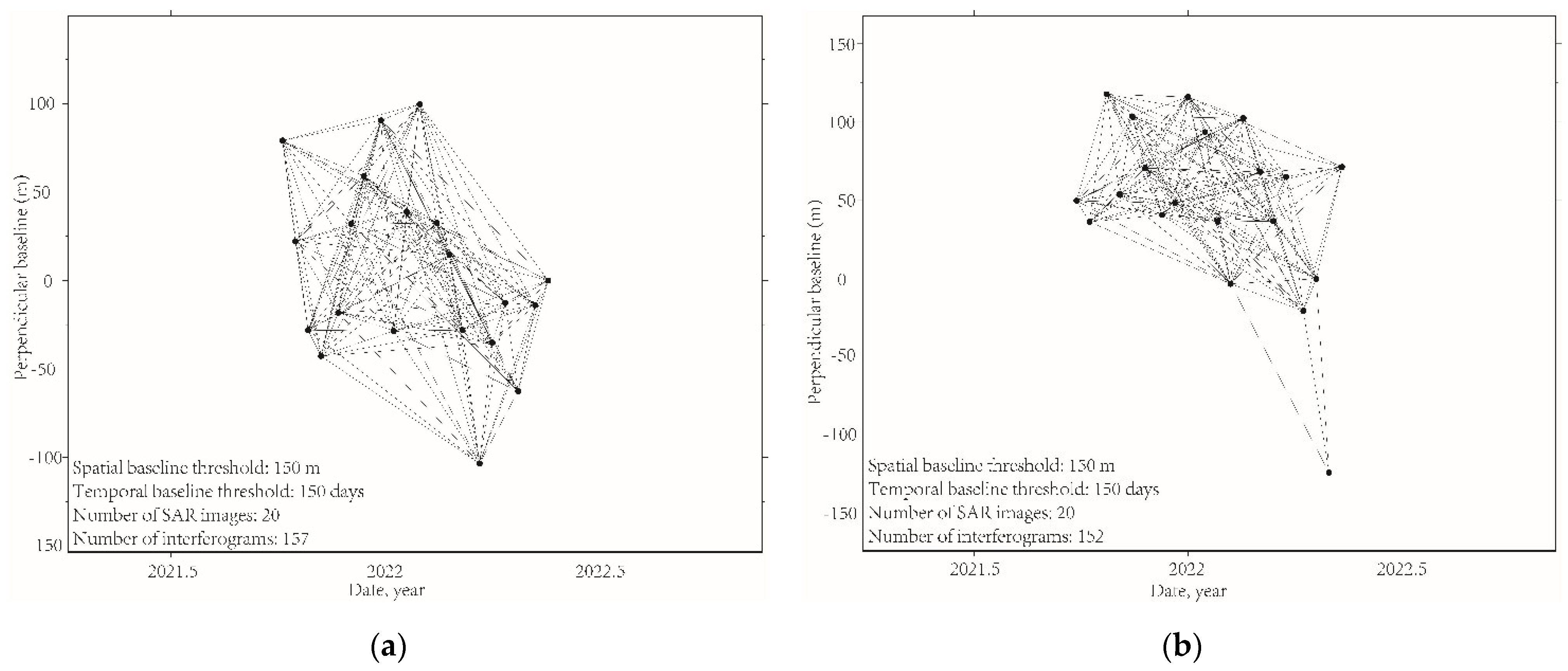
In this study, 157 interferograms derived from 20 scenes of ascending SAR images together with 152 interferograms derived from 20 scenes of descending SAR images were firstly unwrapped using the Statistical-cost, Network-flow Algorithm for Phase Unwrapping (SNAPHU) method [42]. Then, the unwrapped phases were corrected using GAGOS. Furthermore, they were resampled to the same grid and cut to the common area in the WGS-84 geosystem. In the following MSBAS processing, we applied the Tikhonov regularization [41] to solve the ill-posed problem caused by rank deficiency. The regularization was similar to a temporal filter that removed the high-frequency noises [31]; thus, no additional temporal filtering was applied. Then, a 2D low-pass filtering in the spatial domain was implemented to mitigate the residue noise. A trade-off value of 0.25 for the regularization parameter [31,34] was used in this study. The outputs of the MSBAS processing were the 2D deformation rate maps and the accumulative time-series behaviors of certain points. All interferograms were produced by the batch processor of the open-source GMTSAR software [43] based on the standard SBAS network of the interferometric combinations.

3.4. Reference Point Selecting

InSAR measurements, including D-InSAR and time-series methods, are relative to a reference point that is stable during the SAR acquisitions [44]. To maintain the homogeneity of the multiple InSAR measurements, in this study, we selected the same reference point to calibrate all the interferograms of D-InSAR and stack calculated from ascending and descending tracks, respectively. Coherence is a common indicator for reference point selection [44]. The coherence threshold of the reference point was commonly suggested to be above 0.85 [45]. The distance between the reference point and the area of interest should not be too large because of potential APS propagations [46].
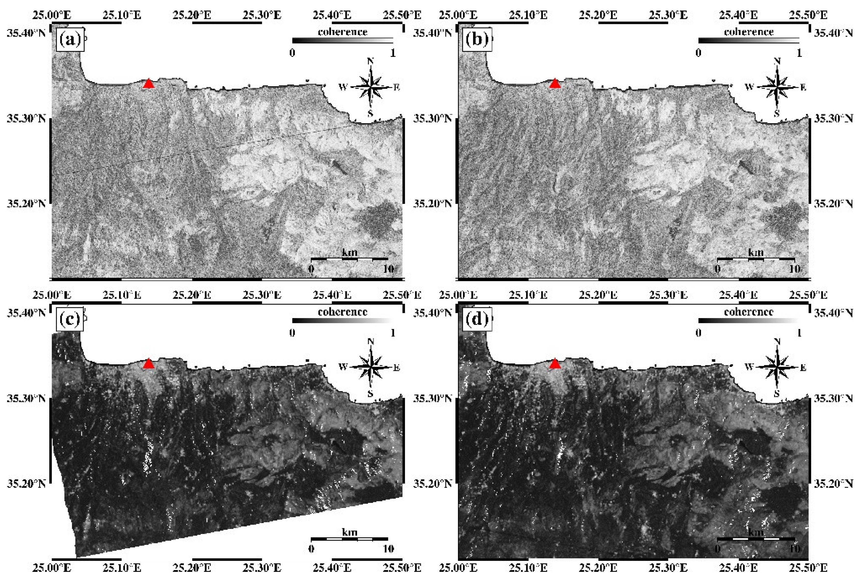
We obtained 4 coherence maps in total (Figure 3), two of them were from ascending and descending D-InSAR processing. The other two coherence maps are calculated by averaging the 157 ascending interferograms and 152 descending interferograms. Finally, the point that was close to the HCW was selected which was maintained to be highly coherent in all of the 4 coherence maps. The coherence of this reference point was 0.927, 0.939, 0.928, and 0.940, respectively, in ascending D-InSAR (Figure 3a), descending D-InSAR (Figure 3b), and ascending stack (Figure 3c), descending stack (Figure 3d). The distance between the reference point and the epicenter was ~25 km.
The selected reference point was next to the HCW. The SAR coherence had indicated high values in 4 independent processing routines. We also check the location of the reference point in an optical Google Map image. The reference point was located at a low building area as shown in Figure 4.

4. Results

4.1. The 2D Co-Seismic Deformations

4.1.1. GACOS Corrections

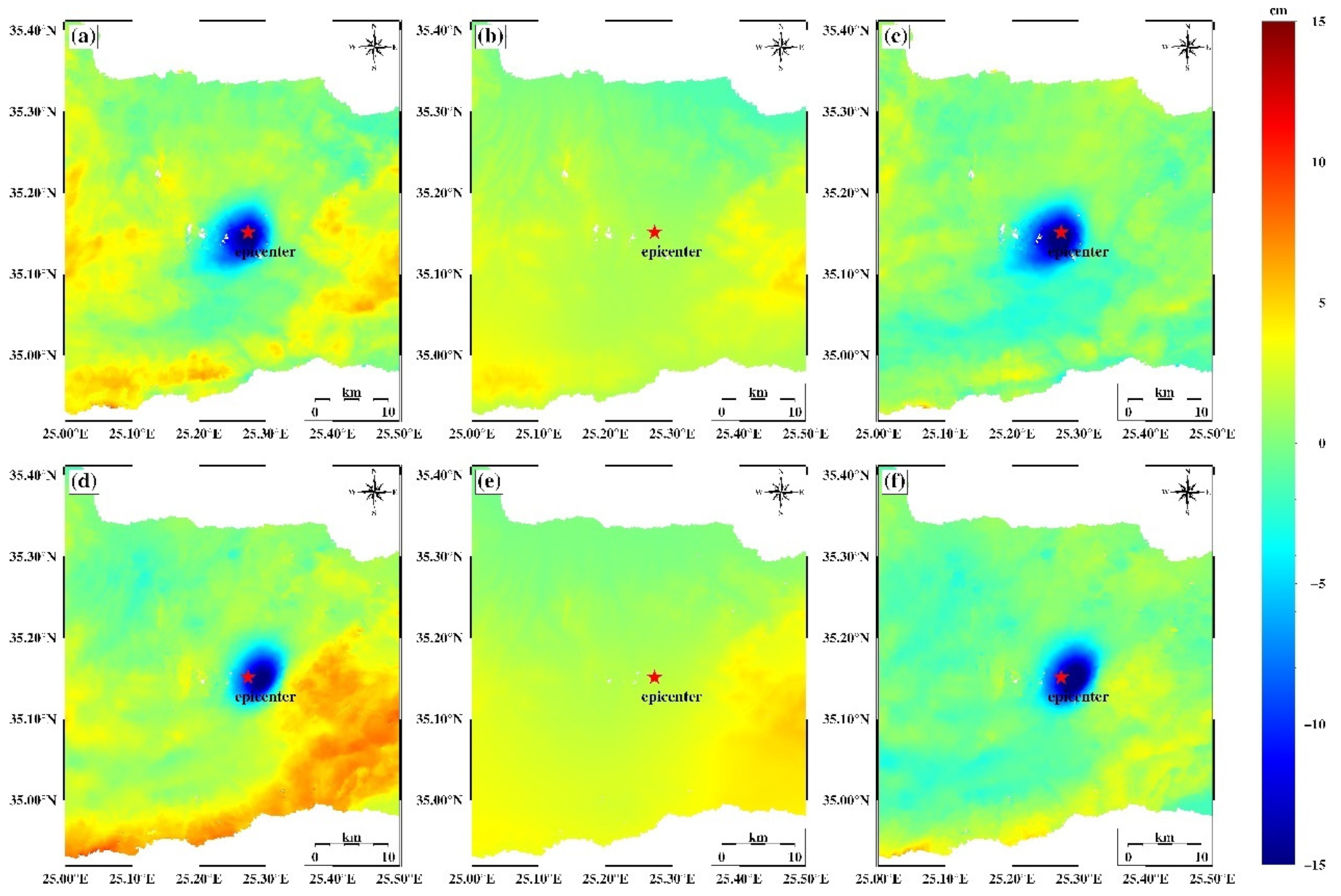
We applied GACOS corrections to mitigate the APS in D-InSAR interferograms. As shown in Figure 5, the qualities of the interferograms were improved. There were obvious tropospheric phase delays simulated by GACOS (Figure 5b,e). The deformations contributed by the APS reached ~6 cm to ~8 cm, which was approximately the same magnitude as the co-seismic deformation, which was not ignorable. The simulated APSs from GACOS had the same pattern as the phases in the uncorrected interferograms. After the GACOS corrections, the corresponding phase patterns were mitigated (Figure 5c,f). Note that we also conducted a phase detrending to remove the long wavelength phase delays according to the GACOS manual (www.gacos.net/ (accessed on 16 October 2022)).

4.1.2. The UD and EW Deformations of the Arkalochori Earthquake

One-dimensional LOS deformation was insufficient to reveal the real ground motions [47,48]. We used the GACOS-corrected interferograms for the decomposition calculation to obtain the UD and EW deformations. The deformation of the North–South direction was ignored because current SAR satellites operated in near-polar orbits, the LOS observations measured from both ascending- and descending-looking geometries were strongly sensitive to the deformation along the UD direction, modestly sensitive along the EW direction, and weakly sensitive along the North–South direction [47].
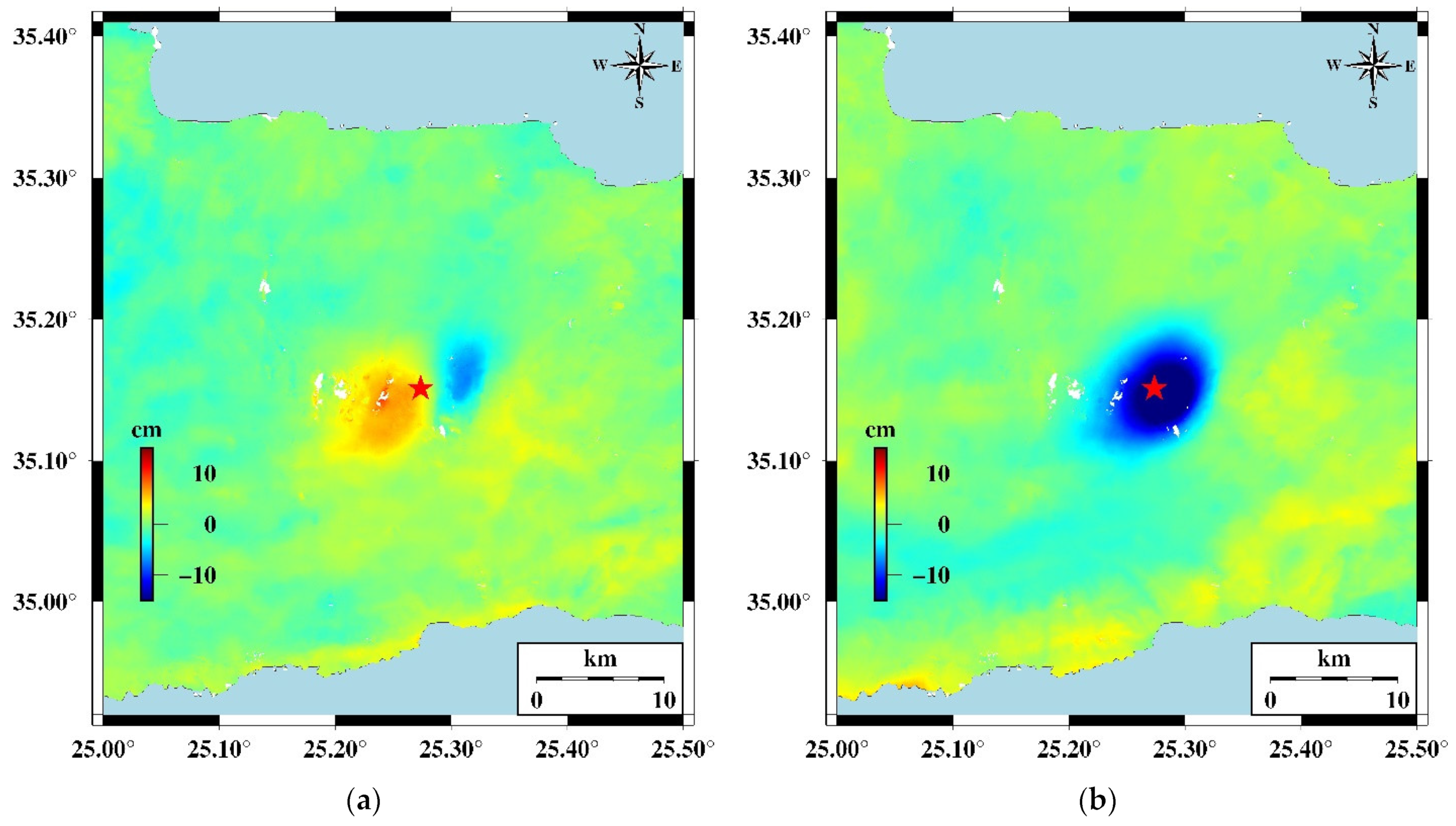
The co-seismic deformation shown in Figure 6 suggested the feature of the ground motions caused by the earthquake was mainly downward (or subsidence). The maximum downward deformation reached ~21 cm. The eastward deformation was about 10 cm and the westward deformation was ~9 cm. Compared with the near-field deformations, the deformations of the ~25 km where the HCW was located were much smaller (Table 3).

4.2. InSAR Time-Series Measurements

4.2.1. Interferogram Stacks

The MSBAS processing is an advanced SBAS-based time-series algorithm that required stacks of interferograms from at least two different view geometries. Based on the conventional small baseline pair selection principle in the SBAS method [49], we constructed two stacks of interferograms from the ascending and descending track, respectively. For the ascending stack, the image acquired on 22 May 2022 was selected as the super reference image, as for the descending stack, the image acquired on 22 April 2022 was selected as the super reference. The super reference images were selected since they were located in the middle of the clouds of baselines (Figure 7). All other images were co-registered with the selected super reference images, respectively, for the two stacks. The threshold of the spatial and temporal baseline is 150 days and 150 m. The interferometric combinations were shown in Figure 7. We get 157 and 152 pairs of interferograms, respectively from the ascending and descending tracks.
The GACOS plus the spatial–temporal filtering strategy was more capable to get better time-series results [50]. Accordingly, we also applied the GACOS corrections to all the total 309 interferograms to mitigate the APS.

4.2.2. MSBAS Results

The outputs of the MSBAS processing are 2D deformation rate maps and accumulative deformation evolution of a certain point over time. As introduced in detail in [33,51], the MSBAS algorithm made a boundary correction along the timeline of SAR acquisition dates, that was, at both ends of the period, the first and the last interferogram were compensated, making the first and last SAR acquisition date to be assumed the same with the adjacent one. Particularly in our case, there were 40 SAR images in total, while the final outputs of the MSBAS processing consisted of 38 independent time spots throughout the entire period.
Starting with the GACOS corrected interferograms, the MSBAS processing was conducted. By joint decompaction, the UD and EW deformation velocity maps were shown in Figure 8. Note that, the MSBAS method could only extract the common footprint of all the data sets that were used in the processing (Figure 3c,d) [31]. For the epicenter area, the EW deformation rate was less than 1 cm/year slightly toward the west, while the UD deformation rate was ~2 cm/year downward, indicating the effect of the mainshock continued with a long-lasting post-seismic ground motion in the following 8 months mainly in the vertical direction. For the HCW, the ground was relatively stable compared with the epicenter area. Both the EW and UD deformation rates were less than 1 cm/year. The database of the faults plotted in Figure 8 was referred to in [7].
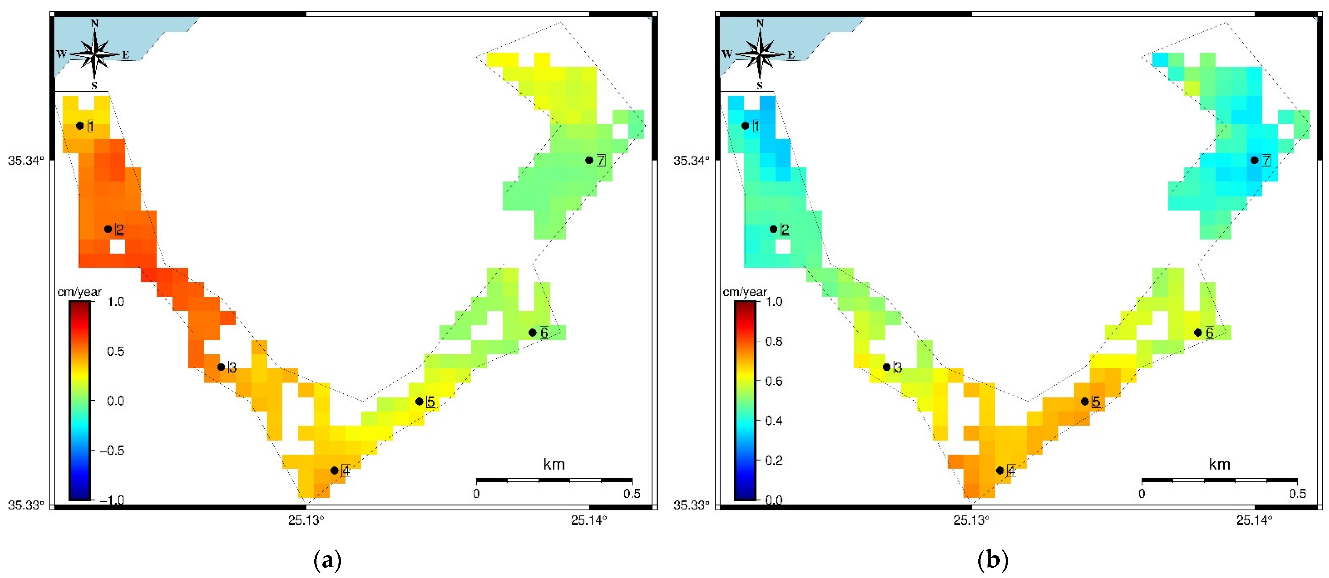
Then, we focused on the deformation velocity of the HCW relic. The zoom-in 2D velocity maps were shown in Figure 9. In the EW direction, the westward deformation velocity was smaller than the eastward one. The western part moves faster than the eastern part. The EW deformation velocity of bastions NO. 1, 2, 3, and 4 ranges from ~0.25 cm/year to ~1 cm/year toward the east, respectively. In the vertical UD direction, the HCW generally showed motion uplift, the southern parts moved faster with a velocity of ~0.8 cm/year, while the northern parts moved slower with a velocity of ~0.2 cm/year to ~0.4 cm/year. The deformation velocity of the Martinengo Bastion (NO. 4) was the fastest compared with the other six bastions, this was because the Martinengo Bastion was mostly close to the Mw 5.9 epicenter.
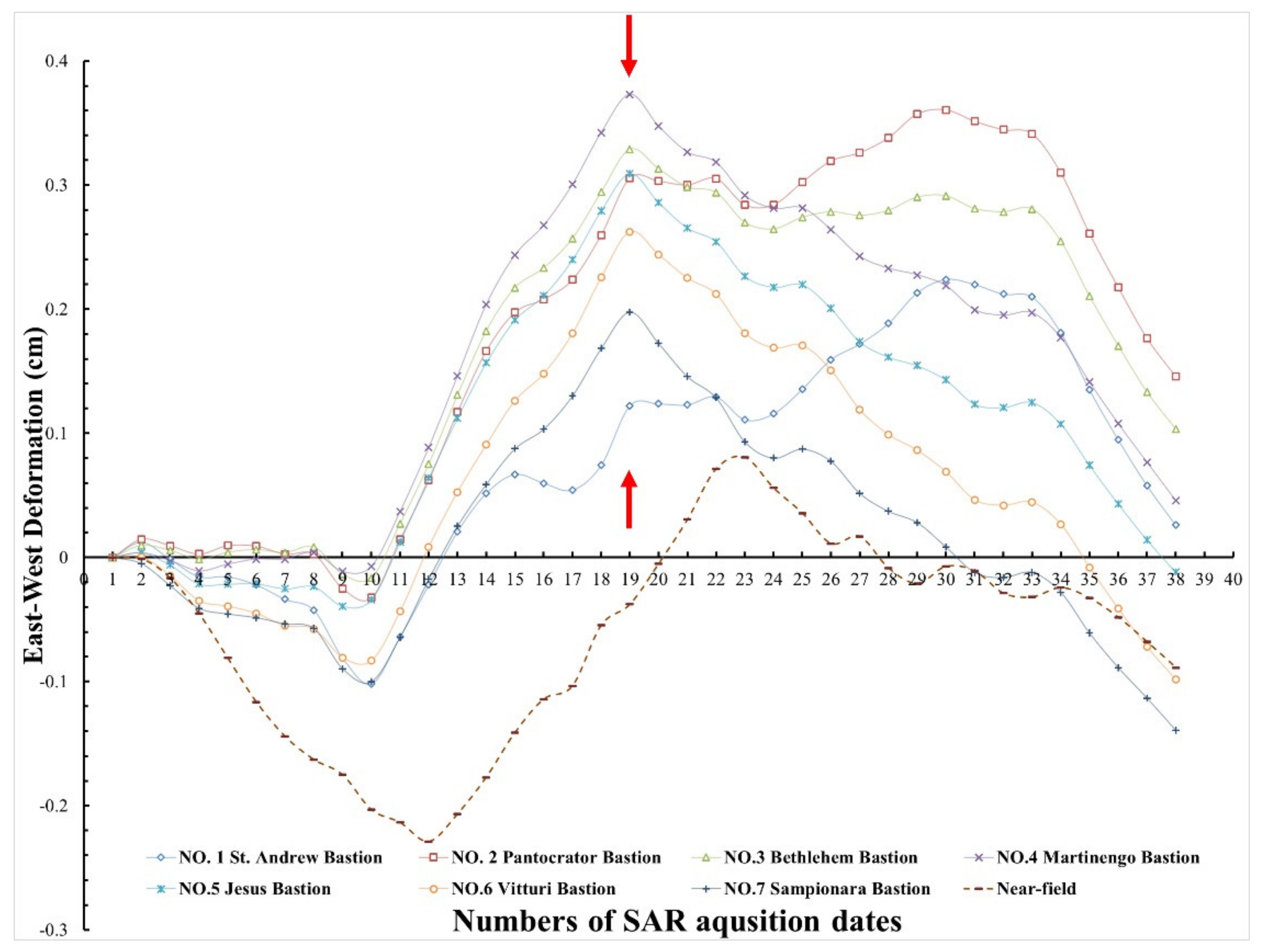
Furthermore, the 2D accumulative defamations were investigated. Note that the near-field time-series deformations were extracted at a point close to the Mw 5.9 epicenter (shown in Figure 8), because at the exact location of the epicenter, the values were not existed due to decorrelations along the more than 300 interferograms. Figure 10 showed the accumulative EW deformations of the seven bastions of the HCW together with the epicenter. It was observed that before the marked time spot, the deformation trend of the HCW was the same as the epicenter, showing a deformation behavior slightly toward the west and then moving toward the east till the marked time spot. The consistent deformation trends between the epicenter and the HCW were interrupted at time spot NO. 19. It was also shown in Figure 8 that there was an earthquake sequence consisting of eight earthquakes with magnitudes larger than 3.5, according to the Institute of Geodynamics of the National Observatory of Athens (NOA-IG), that happened on 16–18 January 2022. The locations of the eight events were ~13 km to the east of the HCW according to the records by NOA-IG. Starting from time spot 19, the EW deformation trend of HCW was different from the Mw 5.9 epicenter. Specifically, the EW deformation of the Mw 5.9 epicenter was eastward, with a relatively fast rate (slope of the deformation curve), but for the HCW, five bastions showed obvious westward motions and the other two bastions showed ~24 days of stabilities. It was observed in Figure 10 that the bastions NO. 3, 4, 5, 6, and 7 were moving toward the west during the NO. 19 and 23 intervals (24 days) with a rate of ~1.56 cm/year while the epicenter was moving toward the east during the same period with a rate of ~1.78 cm/year. The location of the earthquake sequence which happened 4-6 days before the time spot numbered 19 was ~13 km to the east of the HCW, as a result, the bastions NO. 3, 4, 5, 6, and 7 were influenced more because they were nearer to the epicenters of the earthquake sequence. The previous same trends as the Mw 5.9 earthquake were interrupted at the 19th time spot.
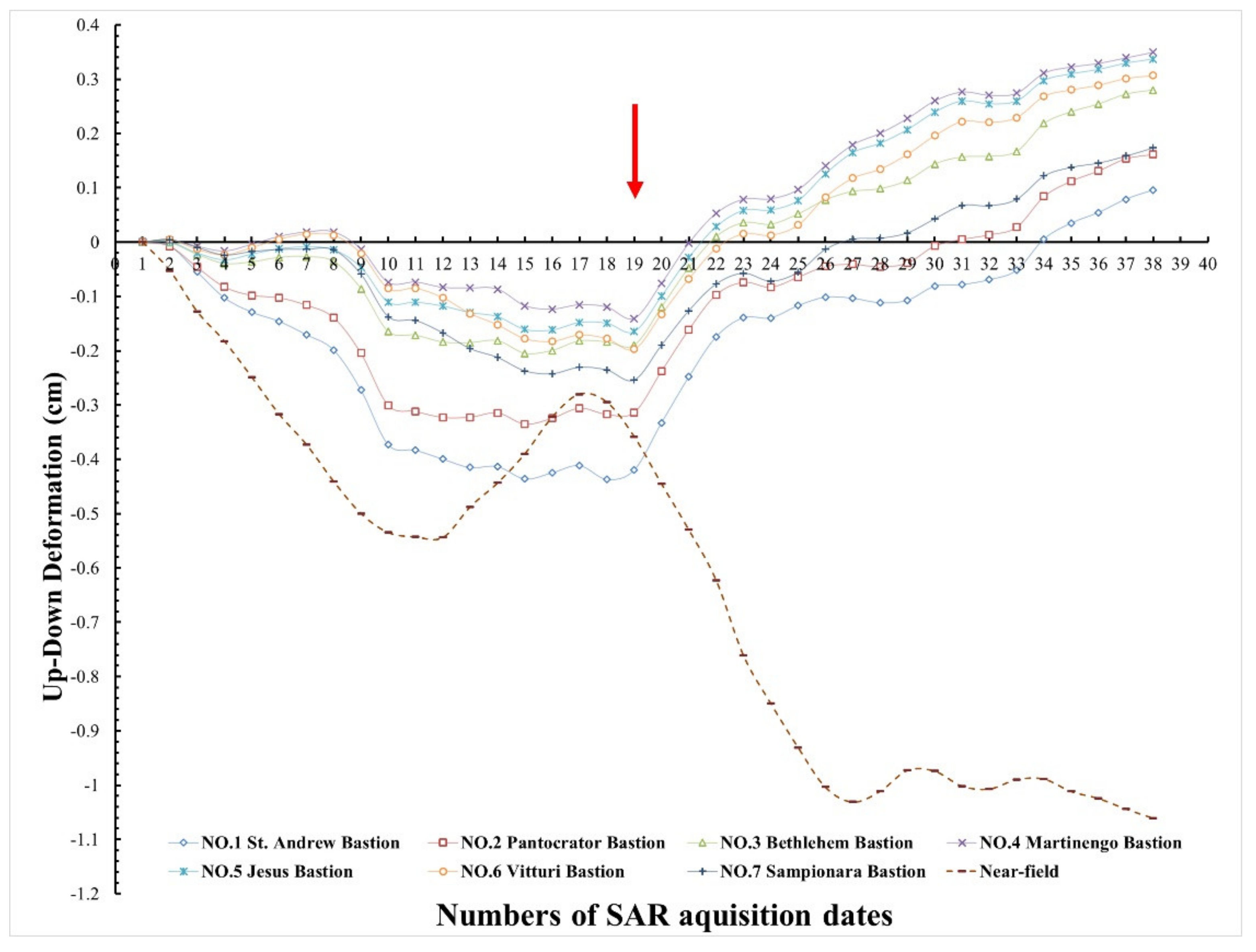
Figure 11 showed the UD accumulative deformations of the seven bastions of the HCW together with the epicenter. Before the marked time spot, the UD motions of the HCW also showed the same trend as the epicenter. This consistent trend was interrupted after the marked time spot, too. After the NO. 19 time spot, the deformation of the Mw 5.9 epicenter area continued to show subsidence, while all of the seven bastions of the HCW were moving uplift during the same time, indicating that the behaviors of the HCW deformations were no more correlated with the Mw 5.9 event. During the whole 8 months observation period after the Mw 5.9 earthquake, the maximum subsidence of the Mw 5.9 epicenter area was ~1.06 cm. Maximum uplift of the HCW was detected at the NO.4 Martinengo Bastion, reaching ~0.35 cm.

5. Discussion

Previous research results [52,53,54,55,56,57,58,59,60] have proven that InSAR technology is mature and provides reliable information on co-seismic and post-seismic deformation monitoring. Although we didn’t have the Global Navigation Satellite System (GNSS) data for direct comparison and validation, as discussed in [21], InSAR had shown an accuracy comparable to the GNSS measurements for the Mw 5.9 Arkalochori earthquake.
The relationship between the Mw 5.9 earthquake and its induced deformation for the HCW was clarified by the InSAR time-series analysis. Meanwhile, we noticed a sudden change in the time-series deformations (Figure 10 and Figure 11, Spot No.19). What caused that sudden change? Was the correlated same trend interrupted by some other disturbances, or there were no relations? The acquisition dates and number identifications of the 40 SAR images together with the earthquake events were shown in Figure 12.
We checked the earthquake catalog released by NOA-IG (https://bbnet.gein.noa.gr/HL/databases/database (accessed on 16 October 2022)) and found there was an earthquake sequence that happened ~13 km away from the HCW on 16–18 January 2022. This earthquake sequence consisted of eight earthquakes, each of which was larger than M 3.5. As shown in Figure 12a, the eight earthquakes happened between the 18th and the 19th time spot along the timeline. The trend interruptions in both EW and UD accumulative deformation curves were observed in the 19th to 20th interval. Since the earthquake sequence marked in Figure 8 happened 1–3 days after the 18th spot (Figure 12a), and the corresponding deformation trend inflections were not detected before the 19th spot. It could be assumed that there was at least a 4–6 day delay for the HCW to show reactions due to the seismic influence of the earthquake sequence, and these reactions were captured by InSAR within a single interval (6 days) in our observation. According to [61], earthquakes could cause potential deformation to a dam; hence, it was assumed that the ~13 km earthquake sequence (Figure 12b) might be the reason that the previous consistent trend between the HCW and the Mw 5.9 earthquake was interrupted. The magnitude of the eight earthquakes in the earthquake sequence was 3.5–3.8 (Figure 12c), and the depth of the epicenter was reported to be 21.2–25.5 km, making it difficult to be detected through D-InSAR measurements. However, it was detectable in the InSAR time-series monitoring thanks to the advantage of the capability and sensitivity in long-lasting micro deformation measuring.
The changing signs of the curve trends in both EW and UD components between spots 10 and 13 were assumed to be related to the aftershocks and afterslips. The dominant driven force of the deformations was interpreted to be the earthquake. Once the main shock occurred, the strain and stress were changed, and the elastic crust started to adjust to the new situation. The afterslips and aftershocks continued to influence this progress. From Figure 1 and Figure 8, we could see that in the period between spots 10 and 13, there were continuous aftershocks in the near-field area but there were no aftershocks larger than M 3.5 near the HCW (Figure 12) until the 18th time spot. After the Mw 5.9 mainshock, the dominant driven force started to take over, and the deformations of HCW acted corresponding to it. The trend sign of EW deformation of HCW at the 10th spot, but the near-field area of the Mw 5.9 epicenter started this sign change ~2 weeks later, this would be related to the continuous aftershocks around the Mw 5.9 epicenter area, but these aftershocks were relatively weak far away (20 km or more) from the HCW; thus, they had less effects on the deformation of HCW. For the UD deformations, the deformations of HCW did not show clear signs of changes but the trends tended to be smoother. The UD sign change of the “Near-field” area was also assumed to be related to the continuous aftershocks in the 10–13 observation intervals because according to the NOA-IG catalog, there were two aftershocks larger than M 3.5. One happened on 3 December 2021 with a magnitude of 3.7 and was buried at 8.3 km in depth, and the other happened on 7 December 2021 with a magnitude of 3.7 and was buried at 9.4 km in depth. The time of these two aftershocks located between the 12th and the 13th spot in the timeline (Figure 12) and the signs of changes of the “Near-field” curves in both EW (Figure 10) and UD (Figure 11) directions also occurred in the same period.
There were small irregular disturbances in both the UD and EW deformation evolutions over time at the HCW relic. These could be the effects related to human activities because the HCW was located in the downtown area of Heraklion city, some parts of the HCW were even reconstructed into modern buildings, playgrounds, or gardens viewed from Google Maps (Figure 4). The spatial–temporal evolutions of deformations were the combinations and reflectors to multiple driven forces [61,62], including earthquakes nearby and far away, the levels of surface water or groundwater, human activities, temperature changes, tectonic movements, local long-term subsidence due to the vicinity to the coastline, and so on. In this case, earthquakes played dominating roles that controlled the general trends of the HCW deformations.
Moreover, there were still residue phase noises in the GACOS corrected and the spatial–temporal filtered interferograms. Fully eliminating the multiple sources of noise remains to be a complex and challenging task [63,64]. Current methodologies could reduce or mitigate the effects of APS and improve the quality of the interferometric measurements among which the GACOS method has been proven to be successful and effective [63,65]. Moreover, the GACOS corrected residue phase components were more suitable to meet the conventional assumption of the APS behaviors in time and space domains [50], making the spatial–temporal filtering option more reliable. These all demonstrated that we had done our best to deal with the APS in this case study under the current condition of the state-of-the-art technology level.
The driven forces that cause the deformations of the HCW could be complicated, among which, we assume that the shake related to the earthquakes played an important role. It can be inferred from Figure 10 and Figure 11 that, the maximum accumulative deformations were no more than 0.2 cm and 0.35 cm in the EW direction and UD direction, respectively. The potential risk of collapse or crack induced by these deformations should be taken into serious consideration in heritage conservation. By investigating and obtaining the amount and direction of the earthquake-induced deformation, the corresponding protection actions should be undertaken. Although the Mw 5.9 and the earthquake sequence of M 3.7, which was close to the HCW, did not cause significant damage to it, the earthquakes did introduce deformations to the wall. The potential risk should be taken care of before there would be further destruction. We also expect further multiple methods such as GNSS, field surveys, modeling, etc., to jointly work on the monitoring and protection of the HCW.

6. Conclusions

Aiming at promoting the heritage impact assessment, the purpose of this study was to investigate the relationships between the Mw 5.9 earthquake and the HCW that was ~25 km away from the epicenter. The results showed that the co-seismic deformation is much larger than the post-seismic deformation. The InSAR time-series method revealed longer-term evolution since it recorded the deformation history over the observed period, which showed the correlation of deformation with the seismic-driven factors. The near-field co-seismic defamation feature was mainly subsidence, the horizontal EW co-seismic deformation was half of the magnitude as the vertical deformation. The APS in the uncorrected interferogram was effectively mitigated by the GACOS correction. The MSBAS time-series analysis showed approximately the same deformation trends between the HCW and the epicenter area of the Mw 5.9 Arkalochori earthquake, indicating the Arkalochori earthquake did influence the deformations of the HCW. The sudden trend interruptions of both the UD and EW deformations, that occurred on 22 January 2022, indicated the existence of an earthquake sequence that happened even nearer on 16–18 January 2022, showing the deformations of the HCW were potentially influenced by another earthquake. The conclusions were made based on the post-seismic analysis using the MSBAS method. To directly answer the aforementioned 3 questions (3Ws): (1) Whether there were any influences between the Arkalochori earthquake and the HCW? Yes, not only the Arkalochori earthquake but also another earthquake sequence nearby contributed to the deformations of the HCW. (2) Where of the HCW suffered most? The closer to the epicenter, the larger the deformation occurred. (3) What kind of relationship there was? The HCW showed approximately the same deformation trends in both UD and EW directions as the epicenter area of the Arkalochori earthquake.
Space technologies link earthquake research and heritage protection together. The study provides new insight for investigating the interactive relations between earthquakes and cultural heritages and could be extended to more case studies such as ancient buildings, tombs, and inscriptions on precipices made from different materials.

Author Contributions

Conceptualization, F.C., H.L., I.P. and M.Z.; methodology, M.Z.; software, M.Z.; formal analysis, F.C., W.Z., H.L. and J.L.; resources, F.C., H.L. and I.P.; writing—original draft preparation, M.Z.; writing—review and editing, F.C., W.Z., H.L. and J.L.; visualization, M.Z.; funding acquisition, F.C., H.L. and I.P. All authors have read and agreed to the published version of the manuscript.

Funding

This research was jointly funded by the National Key Research and Development Program of China [Grant No. 2017YFE0134400], the Innovative Research Program of the International Research Center of Big Data for Sustainable Development Goals [Grant No. CBAS2022IRP06], and the Jiangxi Provincial Technology Innovation Guidance Program (National Science and Technology Award Reserve Project Cultivation Program) [Grant No. 20212AEI91006].

Data Availability Statement

Sentinel-1 SAR images can be quarried and downloaded from European Space Agency (ESA) and the Alaska Satellite Facility (ASF) free of charge. The Precise Orbit Ephemerides of the data are freely available at (https://scihub.copernicus.eu/gnss/#/home (accessed on 16 October 2022)). The GACOS data are provided from (http://www.gacos.net/ (accessed on 16 October 2022)) freely.

Acknowledgments

We thank the GMTSAR and ISCE2 develop teams for providing the open-source InSAR toolboxes. We thank Sergey Samsonov from Canada Centre for Mapping and Earth Observation, Natural Resources Canada, for distributing the SBAS and MSBAS codes. We thank the GACOS team for providing the online atmospheric service. We thank the anonymous reviewers for their constructive comments that improve the quality of the paper.

Conflicts of Interest

The authors declare no conflict of interest.

References

  1. Chen, F.L.; Guo, H.D.; Tapete, D.; Masini, N.; Cigna, F.; Lasaponara, R.; Piro, S.; Lin, H.; Ma, P.F. Interdisciplinary approaches based on imaging radar enable cutting-edge cultural heritage applications. Natl. Sci. Rev. 2021, 8, 2. [Google Scholar] [CrossRef]
  2. Tapete, D.; Cigna, F. InSAR data for geohazard assessment in UNESCO World Heritage sites: Stateof-the-art and perspectives in the Copernicus era. Int. J. Appl. Earth Obs. Geoinf. 2017, 63, 24–32. [Google Scholar] [CrossRef]
  3. Themistocleous, K.; Danezis, C.; Gikas, V. Monitoring ground deformation of cultural heritage sites using SAR and geodetic techniques: The case study of Choirokoitia, Cyprus. Appl. Geomat. 2021, 13, 37–49. [Google Scholar] [CrossRef]
  4. Reale, D.; Noviello, C.; Verde, S.; Cascini, L.; Terracciano, G.; Arena, L. A multi-disciplinary approach for the damage analysis of cultural heritage: The case study of the St. Gerlando Cathedral in Agrigento. Remote Sens. Environ. 2019, 235, 12. [Google Scholar] [CrossRef]
  5. Pastonchi, L.; Barra, A.; Monserrat, O.; Luzi, G.; Solari, L.; Tofani, V. Satellite Data to Improve the Knowledge of Geohazards in World Heritage Sites. Remote Sens. 2018, 10, 992. [Google Scholar] [CrossRef] [Green Version]
  6. Pavlova, I.; Makarigakis, A.; Depret, T.; Jomelli, V. Global overview of the geological hazard exposure and disaster risk awareness at world heritage sites. J. Cult. Herit. 2017, 28, 151–157. [Google Scholar] [CrossRef]
  7. Vassilakis, E.; Kaviris, G.; Kapetanidis, V.; Papageorgiou, E.; Foumelis, M.; Konsolaki, A.; Petrakis, S.; Evangelidis, C.P.; Alexopoulos, J.; Karastathis, V.; et al. The 27 September 2021 Earthquake in Central Crete (Greece)-Detailed Analysis of the Earthquake Sequence and Indications for Contemporary Arc-Parallel Extension to the Hellenic Arc. Appl. Sci. 2022, 12, 2815. [Google Scholar] [CrossRef]
  8. Chen, F.L.; Guo, H.D.; Ishwaran, N.; Liu, J.; Wang, X.Y.; Zhou, W.; Tang, P.P. Understanding the relationship between the water crisis and sustainability of the Angkor World Heritage site. Remote Sens. Environ. 2019, 232, 12. [Google Scholar] [CrossRef]
  9. Chen, F.L.; Guo, H.D.; Ma, P.F.; Lin, H.; Wang, C.; Ishwaran, N.; Hang, P. Radar interferometry offers new insights into threats to the Angkor site. Sci. Adv. 2017, 3, 8. [Google Scholar] [CrossRef] [Green Version]
  10. Cigna, F.; Lasaponara, R.; Masini, N.; Milillo, P.; Tapete, D. Persistent Scatterer Interferometry Processing of COSMO-SkyMed StripMap HIMAGE Time Series to Depict Deformation of the Historic Centre of Rome, Italy. Remote Sens. 2014, 6, 12593–12618. [Google Scholar] [CrossRef]
  11. Cigna, F.; Tapete, D. Tracking Human-Induced Landscape Disturbance at the Nasca Lines UNESCO World Heritage Site in Peru with COSMO-SkyMed InSAR. Remote Sens. 2018, 10, 572. [Google Scholar] [CrossRef] [Green Version]
  12. Drougkas, A.; Verstrynge, E.; Van Balen, K.; Shimoni, M.; Croonenborghs, T.; Hayen, R.; Declercq, P.-Y. Country-scale InSAR monitoring for settlement and uplift damage calculation in architectural heritage structures. Struct. Health Monit. 2020, 2020, 1475921720942120. [Google Scholar] [CrossRef]
  13. Nappo, N.; Peduto, D.; Polcari, M.; Livio, F.; Ferrario, M.F.; Comerci, V.; Stramondo, S.; Michetti, A.M. Subsidence in Como historic centre (northern Italy): Assessment of building vulnerability combining hydrogeological and stratigraphic features, Cosmo-SkyMed InSAR and damage data. Int. J. Disaster Risk Reduct. 2021, 56, 16. [Google Scholar] [CrossRef]
  14. Ma, P.F.; Lin, H.; Wang, W.X.; Yu, H.W.; Chen, F.L.; Jiang, L.M.; Zhou, L.F.; Zhang, Z.J.; Shi, G.Q.; Wang, J.L. Toward Fine Surveillance: A Review of Multitemporal Interferometric Synthetic Aperture Radar for Infrastructure Health Monitoring. IEEE Geosci. Remote Sens. Mag. 2022, 10, 207–230. [Google Scholar] [CrossRef]
  15. Tzouvaras, M.; Kouhartsiouk, D.; Agapiou, A.; Danezis, C.; Hadjimitsis, D.G. The Use of Sentinel-1 Synthetic Aperture Radar (SAR) Images and Open-Source Software for Cultural Heritage: An Example from Paphos Area in Cyprus for Mapping Landscape Changes after a 5.6 Magnitude Earthquake. Remote Sens. 2019, 11, 1766. [Google Scholar] [CrossRef] [Green Version]
  16. Agapiou, A.; Lysandrou, V. Detecting Displacements Within Archaeological Sites in Cyprus After a 5.6 Magnitude Scale Earthquake Event Through the Hybrid Pluggable Processing Pipeline (HyP3) Cloud-Based System and Sentinel-1 Interferometric Synthetic Aperture Radar (InSAR) Analysis. IEEE J. Sel. Top. Appl. Earth Observ. Remote Sens. 2020, 13, 6115–6123. [Google Scholar] [CrossRef]
  17. Agapiou, A. UNESCO World Heritage properties in changing and dynamic environments: Change detection methods using optical and radar satellite data. Herit. Sci. 2021, 9, 14. [Google Scholar] [CrossRef]
  18. Triantafyllou, I.; Karavias, A.; Koukouvelas, I.; Papadopoulos, G.A.; Parcharidis, I. The Crete Isl. (Greece) Mw6.0 Earthquake of 27 September 2021: Expecting the Unexpected. GeoHazards 2022, 3, 106–124. [Google Scholar] [CrossRef]
  19. Vallianatos, F.; Karakonstantis, A.; Michas, G.; Pavlou, K.; Kouli, M.; Sakkas, V. On the Patterns and Scaling Properties of the 2021–2022 Arkalochori Earthquake Sequence (Central Crete, Greece) Based on Seismological, Geophysical and Satellite Observations. Appl. Sci. 2022, 12, 7716. [Google Scholar] [CrossRef]
  20. Peleli, S.; Kouli, M.; Vallianatos, F. Satellite-Observed Thermal Anomalies and Deformation Patterns Associated to the 2021, Central Crete Seismic Sequence. Remote Sens. 2022, 14, 3413. [Google Scholar] [CrossRef]
  21. Ganas, A.; Hamiel, Y.; Serpetsidaki, A.; Briole, P.; Valkaniotis, S.; Fassoulas, C.; Piatibratova, O.; Kranis, H.; Tsironi, V.; Karamitros, I.; et al. The Arkalochori Mw = 5.9 Earthquake of 27 September 2021 Inside the Heraklion Basin: A Shallow, Blind Rupture Event Highlighting the Orthogonal Extension of Central Crete. Geosciences 2022, 12, 220. [Google Scholar] [CrossRef]
  22. Crosetto, M.; Monserrat, O.; Cuevas-Gonzalez, M.; Devanthery, N.; Crippa, B. Persistent Scatterer Interferometry: A review. ISPRS-J. Photogramm. Remote Sens. 2016, 115, 78–89. [Google Scholar] [CrossRef] [Green Version]
  23. Yu, C.; Li, Z.H.; Penna, N.T. Interferometric synthetic aperture radar atmospheric correction using a GPS-based iterative tropospheric decomposition model. Remote Sens. Environ. 2018, 204, 109–121. [Google Scholar] [CrossRef]
  24. Yu, C.; Li, Z.H.; Penna, N.T.; Crippa, P. Generic Atmospheric Correction Model for Interferometric Synthetic Aperture Radar Observations. J. Geophys. Res.-Solid Earth 2018, 123, 9202–9222. [Google Scholar] [CrossRef]
  25. Yu, C.; Penna, N.T.; Li, Z.H. Generation of real-time mode high-resolution water vapor fields from GPS observations. J. Geophys. Res.-Atmos. 2017, 122, 2008–2025. [Google Scholar] [CrossRef]
  26. Alinia, H.S.; Tiampo, K.F.; Samsonov, S.V.; Gonzalez, P.J. Modelling the elevation-dependent seasonal amplitude of tropospheric delays in GPS time-series using DInSAR and meteorological data. Geophys. J. Int. 2019, 216, 676–691. [Google Scholar] [CrossRef]
  27. Liu, X.J.; Zhao, C.Y.; Zhang, Q.; Yin, Y.P.; Lu, Z.; Samsonov, S.; Yang, C.S.; Wang, M.; Tomas, R. Three-dimensional and long-term landslide displacement estimation by fusing C- and L-band SAR observations: A case study in Gongjue County, Tibet, China. Remote Sens. Environ. 2021, 267, 20. [Google Scholar] [CrossRef]
  28. Samsonov, S. Three-dimensional deformation time series of glacier motion from multiple-aperture DInSAR observation. J. Geod. 2019, 93, 2651–2660. [Google Scholar] [CrossRef] [Green Version]
  29. Samsonov, S.; Baryakh, A. Estimation of Deformation Intensity above a Flooded Potash Mine Near Berezniki (Perm Krai, Russia) with SAR Interferometry. Remote Sens. 2020, 12, 3215. [Google Scholar] [CrossRef]
  30. Samsonov, S.; Dille, A.; Dewitte, O.; Kervyn, F.; d’Oreye, N. Satellite interferometry for mapping surface deformation time series in one, two and three dimensions: A new method illustrated on a slow-moving landslide. Eng. Geol. 2020, 266, 13. [Google Scholar] [CrossRef]
  31. Samsonov, S.; d’Oreye, N. Multidimensional time-series analysis of ground deformation from multiple InSAR data sets applied to Virunga Volcanic Province. Geophys. J. Int. 2012, 191, 1095–1108. [Google Scholar] [CrossRef] [Green Version]
  32. Samsonov, S.; d’Oreye, N.; Smets, B. Ground deformation associated with post-mining activity at the French-German border revealed by novel InSAR time series method. Int. J. Appl. Earth Obs. Geoinf. 2013, 23, 142–154. [Google Scholar] [CrossRef]
  33. Samsonov, S.V.; d’Oreye, N. Multidimensional Small Baseline Subset (MSBAS) for Two-Dimensional Deformation Analysis: Case Study Mexico City. Can. J. Remote Sens. 2017, 43, 318–329. [Google Scholar] [CrossRef]
  34. Samsonov, S.V.; d’Oreye, N.; Gonzalez, P.J.; Tiampo, K.F.; Ertolahti, L.; Clague, J.J. Rapidly accelerating subsidence in the Greater Vancouver region from two decades of ERS-ENVISAT-RADARSAT-2 DInSAR measurements. Remote Sens. Environ. 2014, 143, 180–191. [Google Scholar] [CrossRef] [Green Version]
  35. Morishita, Y.; Kobayashi, T.; Yarai, H. Three-dimensional deformation mapping of a dike intrusion event in Sakurajima in 2015 by exploiting the right- and left-looking ALOS-2 InSAR. Geophys. Res. Lett. 2016, 43, 4197–4204. [Google Scholar] [CrossRef] [Green Version]
  36. Agram, P.S.; Gurrola, E.M.; Lavalle, M.; Sacco, G.F.; Rosen, P.A. The InSAR Scientific Computing Environment (ISCE): An Earth Science SAR Processing Framework, Toolbox, and Foundry. In Proceedings of the Agu Fall Meeting, San Francisco, CA, USA, 16 December 2016. [Google Scholar]
  37. Goldstein, R.M.; Werner, C.L. Radar interferogram filtering for geophysical applications. Geophys. Res. Lett. 1998, 25, 4035–4038. [Google Scholar] [CrossRef] [Green Version]
  38. Goldstein, R.M.; Zebker, H.A.; Werner, C.L. Satellite radar interferometry: Two-dimensional phase unwrapping. Radio Sci. 1988, 23, 713–720. [Google Scholar] [CrossRef] [Green Version]
  39. Delbridge, B.G.; Burgmann, R.; Fielding, E.; Hensley, S.; Schulz, W.H. Three-dimensional surface deformation derived from airborne interferometric UAVSAR: Application to the Slumgullion Landslide. J. Geophys. Res.-Solid Earth 2016, 121, 3951–3977. [Google Scholar] [CrossRef] [Green Version]
  40. Zhang, Z.Y.; Lou, Y.D.; Zhang, W.X.; Wang, H.; Zhou, Y.Z.; Bai, J.N. On the Assessment GPS-Based WRFDA for InSAR Atmospheric Correction: A Case Study in Pearl River Delta Region of China. Remote Sens. 2021, 13, 3280. [Google Scholar] [CrossRef]
  41. Tikhonov, A.N.; Arsenin, V.Y. Solution of Ill-Posed Problem; V.H. Winston and Sons: New York, NY, USA, 1977. [Google Scholar]
  42. Chen, C.W.; Zebker, H.A. Phase unwrapping for large SAR interferograms: Statistical segmentation and generalized network models. IEEE Trans. Geosci. Remote Sens. 2002, 40, 1709–1719. [Google Scholar] [CrossRef]
  43. Sandwell, D.; Mellors, R.; Tong, X.; Wei, M.; Wessel, P. Open radar interferometry software for mapping surface Deformation. Eos Trans. AGU 2011, 92, 234. [Google Scholar] [CrossRef] [Green Version]
  44. Zebker, H. Accuracy of a Model-Free Algorithm for Temporal InSAR Tropospheric Correction. Remote Sens. 2021, 13, 409. [Google Scholar] [CrossRef]
  45. Liao, T.H.; Simard, M.; Denbina, M.; Lamb, M.P. Monitoring Water Level Change and Seasonal Vegetation Change in the Coastal Wetlands of Louisiana Using L-Band Time-Series. Remote Sens. 2020, 12, 2351. [Google Scholar] [CrossRef]
  46. Zhu, M.; Zeng, Q.M.; Jiao, J. Quantitative assessment to the impact of InSAR ionospheric and tropospheric corrections on source parameter modelling: Application to the 4th nuclear test, North Korea. Geophys. J. Int. 2021, 224, 86–99. [Google Scholar] [CrossRef]
  47. Fialko, Y. Probing the mechanical properties of seismically active crust with space geodesy: Study of the coseismic deformation due to the 1992 M(w)7.3 Landers (southern California) earthquake. J. Geophys. Res.-Solid Earth 2004, 109, 19. [Google Scholar] [CrossRef]
  48. Hu, J.; Liu, J.H.; Li, Z.W.; Zhu, J.J.; Wu, L.X.; Sun, Q.; Wu, W.Q. Estimating three-dimensional coseismic deformations with the SM-VCE method based on heterogeneous SAR observations: Selection of homogeneous points and analysis of observation combinations. Remote Sens. Environ. 2021, 255, 16. [Google Scholar] [CrossRef]
  49. Berardino, P.; Fornaro, G.; Lanari, R.; Sansosti, E. A new algorithm for surface deformation monitoring based on small baseline differential SAR interferograms. IEEE Trans. Geosci. Remote Sens. 2002, 40, 2375–2383. [Google Scholar] [CrossRef] [Green Version]
  50. Yu, C.; Li, Z.H.; Penna, N.T. Triggered afterslip on the southern Hikurangi subduction interface following the 2016 Kaikura earthquake from InSAR time series with atmospheric corrections. Remote Sens. Environ. 2020, 251, 17. [Google Scholar] [CrossRef]
  51. Samsonov, S.; Tiampo, K.; Cassotto, R. Measuring the state and temporal evolution of glaciers in Alaska and Yukon using synthetic-aperture-radar-derived (SAR-derived) 3D time series of glacier surface flow. Cryosphere 2021, 15, 4221–4239. [Google Scholar] [CrossRef]
  52. Atzori, S.; Manunta, M.; Fornaro, G.; Ganas, A.; Salvi, S. Postseismic displacement of the 1999 Athens earthquake retrieved by the Differential Interferometry by Synthetic Aperture Radar time series. J. Geophys. Res.-Solid Earth 2008, 113, 14. [Google Scholar] [CrossRef]
  53. Briole, P.; Elias, P.; Parcharidis, I.; Bignami, C.; Benekos, G.; Samsonov, S.; Kyriakopoulos, C.; Stramondo, S.; Chamot-Rooke, N.; Drakatou, M.L.; et al. The seismic sequence of January-February 2014 at Cephalonia Island (Greece): Constraints from SAR interferometry and GPS. Geophys. J. Int. 2015, 203, 1528–1540. [Google Scholar] [CrossRef] [Green Version]
  54. De Novellis, V.; Convertito, V.; Valkaniotis, S.; Casu, F.; Lanari, R.; Tobar, M.F.M.; Pino, N.A. Coincident locations of rupture nucleation during the 2019 Le Teil earthquake, France and maximum stress change from local cement quarrying. Commun. Earth Environ. 2020, 1, 10. [Google Scholar] [CrossRef]
  55. Ganas, A.; Kourkouli, P.; Briole, P.; Moshou, A.; Elias, P.; Parcharidis, I. Coseismic Displacements from Moderate-Size Earthquakes Mapped by Sentinel-1 Differential Interferometry: The Case of February 2017 Gulpinar Earthquake Sequence (Biga Peninsula, Turkey). Remote Sens. 2018, 10, 1089. [Google Scholar] [CrossRef] [Green Version]
  56. Hamiel, Y.; Baer, G.; Kalindekafe, L.; Dombola, K.; Chindandali, P. Seismic and aseismic slip evolution and deformation associated with the 2009-2010 northern Malawi earthquake swarm, East African Rift. Geophys. J. Int. 2012, 191, 898–908. [Google Scholar] [CrossRef] [Green Version]
  57. Hamiel, Y.; Fialko, Y. Structure and mechanical properties of faults in the North Anatolian Fault system from InSAR observations of coseismic deformation due to the 1999 Izmit (Turkey) earthquake. J. Geophys. Res.-Solid Earth 2007, 112, 12. [Google Scholar] [CrossRef] [Green Version]
  58. Ilieva, M.; Briole, P.; Ganas, A.; Dimitrov, D.; Elias, P.; Mouratidis, A.; Charara, R. Fault plane modelling of the 2003 August 14 Lefkada Island (Greece) earthquake based on the analysis of ENVISAT SAR interferograms. Tectonophysics 2016, 693, 47–65. [Google Scholar] [CrossRef]
  59. Melgar, D.; Ganas, A.; Taymaz, T.; Valkaniotis, S.; Crowell, B.W.; Kapetanidis, V.; Tsironi, V.; Yolsal-Cevikbilen, S.; Ocalan, T. Rupture kinematics of 2020 January 24 M-w 6.7 Doganyol-Sivrice, Turkey earthquake on the East Anatolian Fault Zone imaged by space geodesy. Geophys. J. Int. 2020, 223, 862–874. [Google Scholar] [CrossRef]
  60. Taymaz, T.; Ganas, A.; Yolsal-Cevikbilen, S.; Vera, F.; Eken, T.; Erman, C.; Keles, D.; Kapetanidis, V.; Valkaniotis, S.; Karasante, I.; et al. Source Mechanism and Rupture Process of the 24 January 2020 Mw 6.7 Doganyol-Sivrice Earthquake obtained from Seismological Waveform Analysis and Space Geodetic Observations on the East Anatolian Fault Zone (Turkey). Tectonophysics 2021, 804, 29. [Google Scholar] [CrossRef]
  61. Neokosmidis, S.; Elias, P.; Parcharidis, I.; Briole, P. Deformation estimation of an earth dam and its relation with local earthquakes, by exploiting multitemporal synthetic aperture radar interferometry: Mornos dam case (Central Greece). J. Appl. Remote Sens. 2016, 10, 16. [Google Scholar] [CrossRef]
  62. Zhou, W.; Chen, F.L.; Guo, H.D. Differential Radar Interferometry for Structural and Ground Deformation Monitoring: A New Tool for the Conservation and Sustainability of Cultural Heritage Sites. Sustainability 2015, 7, 1712–1729. [Google Scholar] [CrossRef]
  63. Kirui, P.K.; Reinosch, E.; Isya, N.; Riedel, B.; Gerke, M. Mitigation of Atmospheric Artefacts in Multi Temporal InSAR: A Review. PFG-J. Photogramm. Remote Sens. Geoinf. Sci. 2021, 89, 251–272. [Google Scholar] [CrossRef]
  64. Li, Z.W.; Cao, Y.M.; Wei, J.C.; Duan, M.; Wu, L.X.; Hou, J.X.; Zhu, J.J. Time-series InSAR ground deformation monitoring: Atmospheric delay modeling and estimating. Earth-Sci. Rev. 2019, 192, 258–284. [Google Scholar] [CrossRef]
  65. Murray, K.D.; Bekaert, D.P.S.; Lohman, R.B. Tropospheric corrections for InSAR: Statistical assessments and applications to the Central United States and Mexico. Remote Sens. Environ. 2019, 232, 12. [Google Scholar] [CrossRef]
Figure 1. Study area. Red star represents the epicenter of the 2021 Mw 5.9 Arkalochori earthquake; red triangle marks the location of the reference point; yellow rectangular means the area of the city of Heraklion. Brown dots represents the shocks with a magnitude larger than 3.5 after the Mw 5.9 mainshock.
Remotesensing 14 05212 g001
Figure 2. The Heraklion City Wall and its seven bastions. Red triangle represents the location of the reference point.
Remotesensing 14 05212 g002
Figure 3. The selection of the reference point (Marked with red triangle). (a) Ascending D-InSAR coherence map; (b) descending D-InSAR coherence map; (c) ascending mean coherence calculated from a stack of 157 coherence maps; (d) descending mean coherence calculated from a stack of 152 coherence maps.
Remotesensing 14 05212 g003
Figure 4. The location of the reference point marked by the yellow pin during D-InSAR and MSBAS processing of both ascending and descending SAR images. The background is Google Map. The red line represented the outline of the Sampionara Bastion.
Remotesensing 14 05212 g004
Figure 5. The GACOS corrections in D-InSAR processing. Positive value means uplift along the LOS direction. (a) Ascending uncorrected interferogram; (b) Tropospheric phase delay of the ascending interferogram calculated from GACOS; (c) GACOS corrected ascending interferogram; (d) Descending uncorrected interferogram; (e) Tropospheric phase delay of the descending interferogram calculated from GACOS; (f) GACOS corrected descending interferogram.
Remotesensing 14 05212 g005
Figure 6. Two-dimensional co-seismic deformation field. The red star means the location of the epicenter. (a) EW deformation, positive to the east; (b) UD deformation, positive uplift.
Remotesensing 14 05212 g006
Figure 7. The networks of interferometric combinations for SBAS processing. Note that the 2021.5 and 2022.5 mean the half of a year, not the month of May. (a) Ascending track; (b) descending Track.
Remotesensing 14 05212 g007
Figure 8. Two-dimensional deformation rate maps. The brown line represents the outline of the HCW. Black dash line marked the location of the 16-18 January, 2022, earthquake sequence larger than M 3.5 recorded by NOA-IG. Brown dots represent the earthquake events larger than M 3.5 during the entire observing period. Black solid lines represent the known faults referred to [7]. (a) EW deformation rates, positive to the east; (b) UD deformation rates, positive uplift.
Remotesensing 14 05212 g008
Figure 9. Two-dimensional deformation rates at the HCW site, the 7 black dots represent the 7 bastions as in Figure 2. (a) EW deformation rates, positive to the east; (b) UD deformation rates, positive uplift.
Remotesensing 14 05212 g009
Figure 10. The EW accumulative deformation at the 7 bastions of the HCW and the epicenter. Positive value represents deformation eastward.
Remotesensing 14 05212 g010
Figure 11. The UD accumulative deformation of the 7 bastions of the HCW and the epicenter. Positive value means uplift.
Remotesensing 14 05212 g011
Figure 12. The timeline and each SAR acquisition date with number identifications and the earthquake sequence on 16–18 January 2022. As described in Section 4.2.2, the first date 30 September 2021 and the last date 22 May 2022 were assumed the same as the adjacent one. (a) Timeline and each SAR acquisition date with number identifications, red stars represent earthquakes that happened on 16 January 2022 (1 event), 17 January 2022 (6 events on the same date) and 18 January 2022 (1 event); (b) locations of the 8 earthquakes with magnitudes larger than 3.5, red rectangular shows the HCW location, yellow rectangular shows where the earthquake sequence located; (c) detailed information of the 8 earthquakes.
Remotesensing 14 05212 g012
Table 1. SAR parameters used for D-InSAR processing.
Platform (Mode)Track/FrameReference/Repeat Date (YYYYMMDD)Incidence Angle (°)Heading 1 (°)Perpendicular Baseline (m)
Sentinel-1A (TOPS)
Ascending
102/11317 September 2021/
29 September 2021
44.002−12.95769.879
102/108
Sentinel-1A (TOPS)
Descending
109/47618 September 2021/
30 September 2021
33.927−166.997−22.354
1 Positive clockwise from the North.
Table 2. SAR parameters used for time-series InSAR processing.
Interferogram StackIncidence Angle (°)Heading 1 (°)Temporal CoverageNumber of SAR ImagesNumber of Interferograms
Sentinel-1A (TOPS)
Ascending Track 029
34.040−13.0786 October 2021–22 May 202220157
Sentinel-1A (TOPS)
Descending Track 109
33.927−166.99730 September 2021–16 May 202220152
Total//6 October 2021–16 May 202240 2307
1 Positive clockwise from the North. 2 Described in Section 4.2.2, due to boundary correction along the timeline, the obtained time series included 38 SAR images. The first ascending and last descending SAR acquisitions were assumed the same as the adjacent one.
Table 3. The co-seismic 2D deformations of the 7 bastions of the HCW and the near-field area of the Mw 5.9 epicenter.
PointEW Deformation 1 (cm)UD Deformation 2 (cm)
1 St. Andrew Bastion−0.080−0.241
2 Pantocrator Bastion−0.186−0.244
3 Bethlehem Bastion−0.372−0.114
4 Martinengo Bastion−0.029−0.239
5 Jesus Bastion−0.044−0.346
6 Vitturi Bation0.088−0.181
7 Sampionara Bastion0.236−0.066
The near-field area6.223−16.489
1 Positive east. 2 Positive up.
Publisher’s Note: MDPI stays neutral with regard to jurisdictional claims in published maps and institutional affiliations.