Abstract
The primary means for electronic position fixing in use in contemporary maritime transport are shipborne GPS (Global Positioning System) receivers or DGPS (Differential GPS) receivers. More advanced GNSS (Global Navigation Satellite System) or RNSS (Regional Navigation Satellite Systems) receivers are able to process combined signals from American GPS, Russian GLONASS, Chinese Beidou (BDS), European Galileo, Indian IRNSS, and Japan QZSS. Satellite-based augmentation systems (SBAS) are still not commonly used in the maritime domain, especially onboard vessels certified under international SOLAS convention. The issues and weaknesses of existing International Maritime Organization recommendations, guidelines, requirements, performance standards, and policies on GNSS shipborne sensors are discussed and presented in the paper. Many problems that have already been dealt with in other means of transportation are still to be solved in the maritime domain. The integrity monitoring is addressed as the main issue, and recommendations based on solutions implemented in aviation and the latest research are proposed. Finally, the strengths, weaknesses, opportunities, and threats awaiting maritime GNSS standardization process are outlined.
1. Introduction
Remote sensing is the main possibility to properly ensure the safety and security of maritime activities, especially in the scope of marine traffic surveillance essential for vessel traffic services (VTS) and control, monitoring of illegal activities, as well as general security and emergency management. The quality of shipborne GNSS (Global Navigation Satellite System) or RNSS (Regional Navigation Satellite System) data forming the backbone of AIS (Automatic Identification System) and other global and regional remote monitoring and traffic service systems remains an open issue. In the paper, the evolution and ongoing research on maritime GNSS performance guidelines and standards are presented as these instruments set the expected boundary performance parameters of shipborne-derived GNSS data. The acronyms and abbreviations used in the regulatory process of the standardization and this paper are listed in the Appendix A.
A regulatory framework to improve the safety and security of international shipping and to prevent pollution from ships is set worldwide by the International Maritime Organization (IMO). This specialized agency of the United Nations (UN) is responsible for the facilitation of maritime traffic in international waters and adopts policies, guidelines, and performance standards for positioning, measuring, detecting, and other navigation, deck, or machinery equipment onboard vessels certified under its Safety of Life at Sea (SOLAS) convention. The IMO’s bodies also represent maritime domain among other intergovernmental and non-governmental organizations worldwide. The IMO started work on the GNSS as part of worldwide radionavigation system (WWRNS) in the 1980s together with the UN International Civil Aviation Organization (ICAO). This was the time of American GPS and Russian (at that time, the Soviet Union) GLONASS development, whose signals could be used worldwide for position-fixing and calculation of a vessel’s speed and course over ground. In 1989, by the IMO resolution A.666(16) [1], the maritime community recognized for the first time the need for a world-wide radionavigation system to provide ships with navigational position-fixing globally. This resolution included the Report on the Study of a World-Wide Radionavigation System as the policy for the recognition and acceptance of suitable radionavigation systems intended for international maritime transport and other activities at sea. The study forming the basis of IMO policy had been conducted since 1983. It determined In the maritime domain: (1) the operational requirements of satellite navigation systems, which should be reliable, of low user cost, and meeting the needs for general navigation, (2) the organizational structure and arrangements which would be needed for such a system to be recognized or accepted by IMO as being suitable for use by ships, and (3) the arrangements by which a national or multinational satellite navigation system might be accepted mutually by other member states for use by their ships. The recognition by IMO of a radionavigation system means that the organization recognizes that the system is capable of providing adequate position information within its coverage area and that the carriage of receiving equipment for use with the system satisfies the relevant requirements of the 1974 SOLAS Convention, as amended. This process is still ongoing and has led to the development of:
- –
- currently binding performance standards for shipborne GNSS receivers set by the resolutions MSC.112(73) on GPS [2], MSC.113(73) on GLONASS [3], MSC.114(73) on DGPS and DGLONASS [4], MSC.115(73) on Combined GPS and GLONASS [5], MSC.233(82) on Galileo [6], MSC.379(93) on Beidou [7], MSC.401(95) on Multi System Shipborne Radionavigation Receivers [8] with MSC.432(98) amendments [9], MSC.449(99) on IRNSS [10], MSC.480(102) on QZSS [11], and the revised resolution A.1046(27) on World Wide Radionavigation System (WWRNS) [12],
- –
- policies and guidelines that are only recommendations as declared in Resolution A.915(22) on Revised maritime policy and requirements for a future GNSS [13], and in Circular MSC.1/Circ.1575 on Guidelines for shipborne position, navigation and timing (PNT) data processing [14].
2. IMO GNSS Policy
Resolutions A.860(20) on maritime policy for a future GNSS and A.915(22) on revised maritime policy and requirements for a future GNSS were adopted by IMO in 1997 [15] and 2001 [13], respectively. This was the time of ground-based and satellite-based augmentation systems (GBAS and SBAS) development whose signals could be used worldwide as an external source of GNSS corrections and integrity data. These resolutions proposed for the first time, but only as a policy to be achieved in a future, internal (user-level) and external (provided by external stations) GNSS data integrity monitoring for shipborne receivers. Integrity monitoring was defined as the process of determining whether the system performance (or individual observations conducted by the system) allows its use for navigation purposes. Overall GNSS system integrity was described by three parameters: the threshold value or alert limit (AL), the time to alarm (TTA), and the integrity risk (IR). Definitions of the following terms were introduced to maritime users:
- Accuracy: The degree of conformance between the estimated or measured parameter of a craft at a given time and its true parameter at that time (parameters in this context may be position coordinates, velocity, time, angle, etc.). Absolute accuracy (geodetic or geographic accuracy) is the accuracy of a position estimate with respect to the geographic or geodetic coordinates of the Earth in WGS84.
- Integrity: The ability to provide users with warnings within a specified time when the system should not be used for navigation.
- Craft autonomous integrity monitoring (CAIM): This is a technique whereby various navigation sensor information available on the craft is autonomously processed to monitor the integrity of the navigation signals.
- Receiver autonomous integrity monitoring (RAIM): A technique whereby the redundant information available at a GNSS receiver is autonomously processed to monitor the integrity of the navigation signals.
- Continuity: The probability that, assuming a fault-free receiver, a user will be able to determine position with specified accuracy and is able to monitor the integrity of the determined position over the (short) time interval applicable for a particular operation within a limited part of the coverage area.
- Availability: The percentage of time that an aid, or system of aids, is performing a required function under stated conditions where system availability is the availability of a system to a user, including signal availability and the performance of the user’s receiver.
- Alert limit (AL): The maximum allowable error (or threshold value) in the measured position, during integrity monitoring, before an alarm is triggered.
- Time to alarm (TTA): The time elapsed between the occurrence of a failure in the system and its presentation on the ship’s bridge.
- Integrity risk (IR): The probability that a user will experience a position error larger than AL without an alarm being raised within the specified TTA at any instant of time at any location in the coverage area.
- Coverage: The coverage provided by a radionavigation system is that surface area or space volume in which the signals are adequate to permit the user to determine position to a specified level of performance.
- Latency: The time lag between the navigation observations and the presented navigation solution.
- Chart error (CE): Position errors in the chart caused by inaccuracies in surveying and chart generation, and by errors in the reference geodetic system.
- Navigation system error (NSE): The combined error of the CE and GNSS position estimate (PE) usually referenced to a common consistent reference point (CCRP) and formulated by (1):
- Vessel Technical Error (VTE): This is the difference between the indicated craft position and the indicated command or desired position. It is a measure of the accuracy the craft is controlled with. Components are cross track error (XTE) and along track error (ATE).
- Total System Error (TSE): The overall navigation performance can be described by the TSE. Assuming the contributions to TSE from NSE and VTE are random, the TSE can be described as (2) (Figure 1):
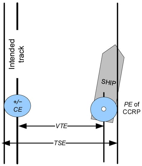
Figure 1.
Contribution of GNSS position error (PE), chart error (CE), and vessel technical error (VTE) to total system error (TSE) according to [13] (own visualization).
Figure 1.
Contribution of GNSS position error (PE), chart error (CE), and vessel technical error (VTE) to total system error (TSE) according to [13] (own visualization).
- Gross errors: Or “outliers”, are errors other than random errors or systematic errors. They are often large and, by definition, unpredictable. They are typically caused by sudden changes in the prevailing physical circumstances, by system faults or operator errors.
- Marginally detectable bias (MDB): The minimum size of gross error in an observation that may be detected with given probabilities of type 1 and type 2 errors. A type 1 error occurs when an observation without a gross error is wrongly rejected, and a type 2 error occurs when an observation with a gross error is wrongly accepted.
- Marginally detectable error (MDE): The maximum position-offset caused by a MDB in one of the observations.
- Reliability of a position fix: A measure of the propagation of a non-detected gross error (outlier) in an observation to the position fix. This “external” reliability is usually expressed in terms of MDE.
Res. A.915(22) also set more detailed performance specifications to GNSS onboard equipment (service level parameters) recommended for the future GNSS (see Table 1):
- 10 m accuracy (95%) and 25 m AL for most applications.
- 10 s TTA.
- 10−5 IR per 3 h.
- 99.97% continuity over 3 h.
- 99.8% overall availability (considered per 30 days).

Table 1.
Minimum maritime user requirements recommended for general navigation derived from IMO Res. A.915(22) [13].
Table 1.
Minimum maritime user requirements recommended for general navigation derived from IMO Res. A.915(22) [13].
| Area | Minimum Maritime User Requirements for General Navigation | |||||||
|---|---|---|---|---|---|---|---|---|
| System Level Parameters | Service Level Parameters | |||||||
| Absolute Accuracy | Integrity | Availability (%) (per 30 Days) | Continuity (%) (over 3 h) | Coverage | Fix Interval (s) | |||
| Horizontal 95% (m) | AL (m) | TTA (s) | IR (per 3 h) | |||||
| Ocean | 10 | 25 | 10 | 1.00 × 10⁻⁵ | 99.8 | - | Global | 1 |
| Coastal | 10 | 25 | 10 | 1.00 × 10⁻⁵ | 99.8 | - | Global | 1 |
| Port approach and restricted waters | 10 | 25 | 10 | 1.00 × 10⁻⁵ | 99.8 | 99.97 | Regional | 1 |
| Port | 1 | 2.5 | 10 | 1.00 × 10⁻⁵ | 99.8 | 99.97 | Local | 1 |
| Inland waterways | 10 | 25 | 10 | 1.00 × 10⁻⁵ | 99.8 | 99.97 | Regional | 1 |
However, some of the terms and service parameters were defined ambiguously or without specifying algorithm for their evaluation. For example, there have been no additional explanations given to the Formulas (1) and (2) in resolution A.915(22), so one can assume that (1) either should be treated conservatively as a sum of absolute values for estimation purposes, or it should be transformed to the Euclidean distance form of (2) assuming random contributions from CE and PE.
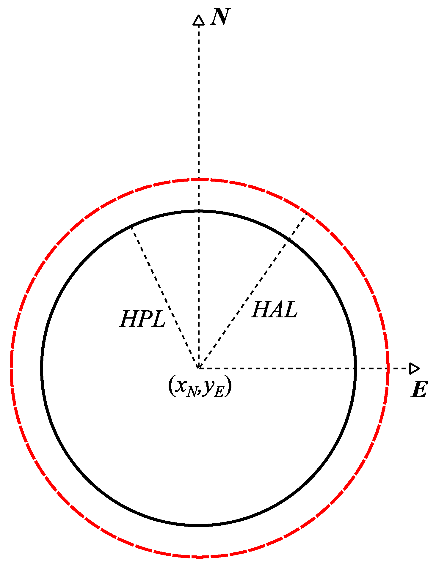
Furthermore, the resolution A.915(22) has not addressed the issue of an algorithm for an upper confidence bound on the position error for IR monitoring. The contemporary shipborne GNSS receivers use mostly RAIM that takes into account either data derived from autonomous GNSS signals without any augmentation or augmented only by Radio Technical Commission for Maritime Services (RTCM)/International Association of Marine Aids to Navigation and Lighthouse Authorities (IALA) differential signals [4,16]. This RAIM is based on the health indicator of GNSS signals and simple consistency tests to exclude faulty or disturbed data but does not use more comprehensive performance indicators provided for individual data to control its influence on potential PNT data output. However, a wide variety of RAIM implementations has been developed in the last decades [17,18]. They are realized not only as snapshot schemes testing only the consistency of current measurement but also as averaging and filtering schemes taking into account previous measurements to compensate effects induced by the vessel’s movement. They differ also in applied search strategies for fault detection and isolation, and, if supported, in methods and parameters used for the determination of PNT data uncertainty level. Ultimately, the diversity of RAIM implementations makes it impossible to achieve a general assignment of RAIM approaches to a single integrity level, whereas the achievement of high-level integrity evaluation as proposed in A.915(22) implicates the necessity to determine the absolute magnitude of significant errors and resulting consequences for the accuracy limits of single PNT output data via GBAS or SBAS in a similar way as it was developed for aviation domain [19,20,21]. In aviation, such a magnitude of significant errors calculated as an upper confidence bound has been named “protection level” (PL—see Figure 2).
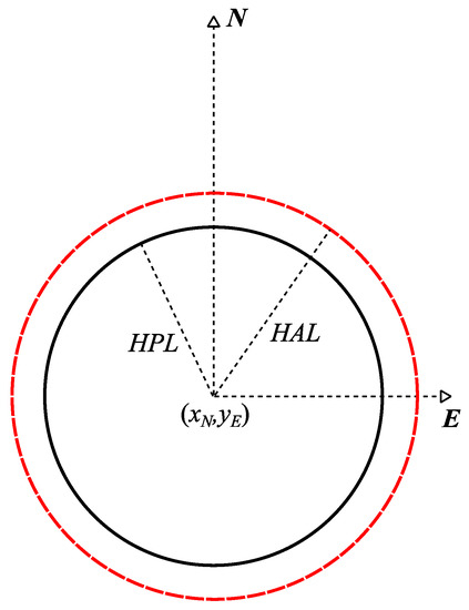
Figure 2.
Horizontal protection level (HPL) and alert limit (HAL) (based on [19]).
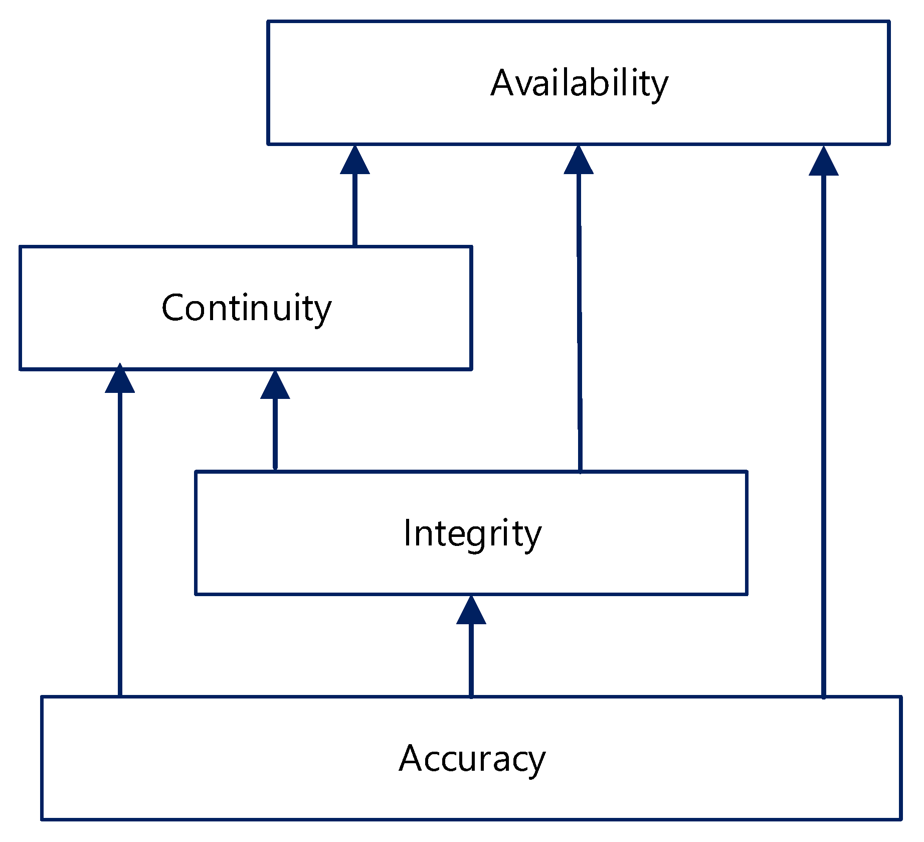
Concluding, the resolution A.915(22) has given grounds for the application of GNSS integrity concept in the maritime domain. Its definition of reliability of position fix is equivalent to the definition of circular PL that was concurrently developed by ICAO and Radio Technical Commission for Aeronautics (RTCA) in the aviation domain [19,22] at the beginning of the 21st century as an upper confidence bound on the error in the position. The high integrity level should be assigned to RAIM implementations supporting the determination of realistic PL as expected bound of position inaccuracies, and the navigation service performance as presented in A.915(22) assumes a hierarchical structure (Figure 3) with positioning accuracy as the basic performance parameter and integrity as the parameter affecting both continuity and availability of GNSS data.
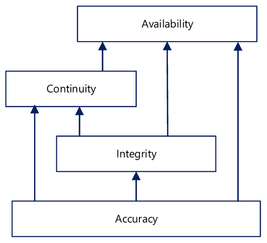
Figure 3.
Dependency and hierarchy of GNSS service performance parameters (based on [13]).
3. IMO GNSS Performance Standards
IMO resolutions on the worldwide radionavigation system and on individual GNSS subsystems performance standards provide manufacturers with currently binding (obligatory) parameters of shipborne receivers to attain their certification by IEC and classification societies [23].
The most important of these resolutions is A.1046(27) on the worldwide radionavigation system [12]. All IMO-recognized radionavigation systems including GNSS must meet the provisions of this resolution or the previous one A.953(23) [24] if recognized before 2011. A.1046(27) contains system-level specifications. It does not address any integrity algorithms and does not refer to A.915(22) explicitly. Nonetheless, it implicitly sets 15 min continuity time-range and indefinite value of availability time-range which was previously set to 30 days. For seafarers, the most important is division of operational requirements into two zones:
- Ocean waters where a radionavigation system is used to assist in the navigation of ships and provides positional information with an error not greater than 100 m with a probability of 95%, and an integrity warning of system malfunction, non-availability or discontinuity is provided to users as soon as practicable by Maritime Safety Information (MSI) systems;
- harbor entrances, harbor approaches, and coastal waters where a radionavigation system provides positional information with an error not greater than 10 m with a probability of 95%, and when the system is available, the service continuity should be ≥99.97% over a period of 15 min and an integrity warning of system malfunction, non-availability or discontinuity should be provided to users within 10 s.
In both zones, signal availability should exceed 99.8% and the system shall be considered available when it provides the required integrity for the given accuracy level. The problematic question is how to evaluate signal availability if no reference time is given—usually the previous 30 days is assumed, but it remains only as declarative non-verifiable statement of GNSS subsystem stakeholder.
The first performance standards for shipborne satellite navigation receivers meeting WWRNS specification were adopted by IMO in resolutions MSC.112(73) on GPS [2], MSC.113(73) on GLONASS [3], MSC.114(73) on DGPS and DGLONASS [4], and MSC.115(73) on Combined GPS and GLONASS [5] in 2000. They specified the following accuracy requirements for equipment installed after July 2003:
- GPS: static accuracy such that the position of the antenna is determined to within 100 m (95%) with horizontal dilution of precision HDOP = 4 (or position dilution of precision PDOP = 6), dynamic accuracy such that the position of the ship is determined to within 100 m (95%) with HDOP = 4 (or PDOP = 6) under the conditions of sea states and ship’s motion likely to be experienced in ships;
- GLONASS: static accuracy such that the position of the antenna is determined to within 45 m (95%) with HDOP = 4 (PDOP = 6), dynamic accuracy such that the position of the antenna is determined to within 45 m (95%) with HDOP = 4 (PDOP = 6) under the conditions of sea states and ship’s motion likely to be experienced in ships;
- DGPS and DGLONASS: static and dynamic accuracies should be 10 m (95%);
- Combined GPS and GLONASS: static accuracy such that the position of the antenna is determined to within 35 m (95%) in non-differential mode and 10 m (95%) in differential mode with HDOP < 4 or PDOP < 6, dynamic accuracy such that the position of the ship is determined to within 35 m (95%) in non-differential mode and 10 m (95%) in differential mode with HDOP < 4 or PDOP < 6 under the conditions of sea states and ship’s motion likely to be experienced in ships;
- all systems receivers: integrity status and alarm for differential IALA modes.
In 2006, the resolution MSC.233(82) [6] on performance standards for shipborne Galileo receiver equipment was adopted. According to this resolution the Galileo shipborne receiver equipment should indicate whether the performance of Galileo is outside the bounds of requirements for general navigation in the ocean, coastal, port approach, and restricted waters, and inland waterway phases of the voyage as specified in either resolution A.953(23) (replaced by A.1046(27)) or Appendix 2 to the resolution A.915(22) and any subsequent amendments as appropriate. Thus, the receiver equipment should as a minimum:
- Have static and dynamic accuracy such that the position of the antenna is determined to within: (i) 15 m horizontal (95%) and 35 m vertical (95%) for single frequency operations on the L1 frequency; (ii) 10 m horizontal (95%) and 10 m vertical (95%) for dual frequency operations on L1 and E5a or L1 and E5b frequencies.
- Provide a warning within 5 s of loss of position or if a new position based on the information provided by the Galileo constellation has not been calculated for more than 1 s for conventional craft and 0.5 s for high-speed craft. Under such conditions, the last known position and the time of last valid fix, with the explicit indication of the state so that no ambiguity can exist, should be output until normal operation is resumed.
- Use RAIM to provide integrity performance appropriate to the operation being undertaken.
- Provide a self-test function.
- For receivers having the capability to process the Galileo Safety of Life Service, integrity monitoring and alerting algorithms should be based on a suitable combination of the Galileo integrity message and RAIM. The receiver should provide an alarm within 10 s TTA of the start of an event if an AL of 25 m Horizontal Alert Limit (HAL) is exceeded for a period of at least 3 s. The probability of detection of the event should be better that 99.999% over a 3 h period (IR ≤ 10−5 through 3 h).
This resolution set the first standards of GNSS subsystem based on A.915(22), and it went a step ahead of GPS and GLONASS performance standards in force at that time and the foreseeable future. Though it set strict requirements of IR that cannot be met even today, it left the problem of exemplary algorithms for integrity monitoring and alerting unresolved.
In 2014, the resolution MSC.379(93) [7] on performance standards for shipborne Beidou receiver equipment was adopted. It followed the provisions of MSC.233(82) for European Galileo with the exception of safety of life service, which is not provided by Beidou and accuracy:
- have static and dynamic accuracy such that the position of the antenna is determined to be within 25 m horizontally (95%) and 30 m vertically (95%).
In 2015, the resolution MSC.401(95) [8] on performance standards for multisystem shipborne radionavigation receivers was adopted. Its aim was to ensure that ships could be provided with resilient position-fixing equipment suitable for use not only with single radionavigation system but with various radionavigation systems available throughout their voyage. This resolution generalized integrity monitoring again by stipulating that the radionavigation equipment should be designed to provide means of integrity monitoring for each position, velocity, and timing (PVT) source employed (e.g., as RAIM or CAIM); and multi-source autonomous integrity monitoring (envisioned to be a cross-check between independent PVT sources). Later, in 2017, this resolution was amended by MSC.432(98) [9]. The amendment was short but meaningful—referring performance standards to the resolutions on stand-alone ship-borne radionavigation receivers: “Type-specific performance standards for stand-alone shipborne radionavigation receivers should be taken into account when conducting type approval for multi-system receivers in accordance with resolution MSC.401(95).” Nevertheless, MSC.401(95) enabled the full use of relevant data originating from current and future radionavigation services, thus it recognized SBAS augmentation data processing [25,26,27] in shipborne radionavigation receivers as well, though not directly.
MSC.449(99) on IRNSS (of operational name NavIC—Navigation with Indian Constellation) adopted in 2018 [10] followed exactly the standards for Beidou with the exception of coverage—a regional system for the Indian Ocean.
MSC.480(102) on QZSS adopted in 2020 [11] followed the one on IRNSS but had different coverage (regional system covering partly Indian and Pacific Ocean from Japan Sea, Korea, Japan, east coast of China, Thailand, Malaysia, Indonesia, Papua New Guinea, Australia to 60° S) and specified accuracy as:
- static accuracy such that, for the service area, where a horizontal dilution of precision (HDOP) is equal to or less than 6.7, the position of the antenna should be determined to within 50.4 m horizontal (95%), dynamic accuracy under the conditions of sea states and ships’ motion likely to be experienced in ships, such that for the service area where a HDOP is equal to or less than 6.7, the position of the antenna should be determined to within 50.4 m horizontal (95%).
It is worth noting that the two systems, IRNSS and QZSS, belong to the RNSS not GNSS, but within their coverage areas, they were recognized as part of WWRNS by IMO in 2020 and 2021, respectively.
Concluding, all obligatory GNSS and RNSS standards are quite conservative for accuracy values, but could be quite demanding if applying integrity values according to A.915(22).
4. Research and Future Development of Maritime GNSS Standards
The research on maritime GNSS IR standard is ongoing as it is currently still not possible to meet the requirements for any of the applications specified in the IMO resolution A. 915(22) without SBAS support or new safety-dedicated services such as Galileo Safety of Life (SoL) or dual frequency services [28]. The first problem to solve is standardization of horizontal PL (HPL) calculation.
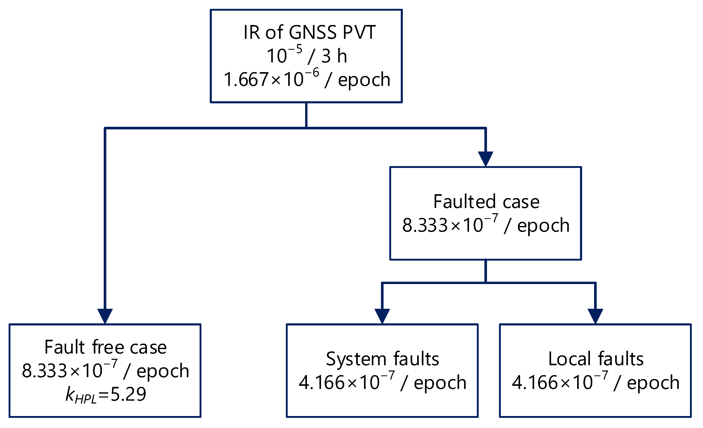
In order to determine horizontal PL value (HPL), the 1σ circular bound on the position error should be derived from augmentation data (precisely semimajor axis of elliptical uncertainty based on standard deviations of coordinates assuming multivariate normal distribution) and multiplier of this bound corresponding to IR (further called a coverage or scale k-factor: kHPL) should be derived from the probability of fault-tree. The maritime world does not have an equivalent to aviation IMO certified top-down fault-tree analysis (FTA) of navigation risks stemming from an allowed Target Level of Safety (TLS) [22] so researchers such as Klepsvik [29] or Hargreaves developed their own [30]. An example of integrity FTA is presented in the Figure 4.
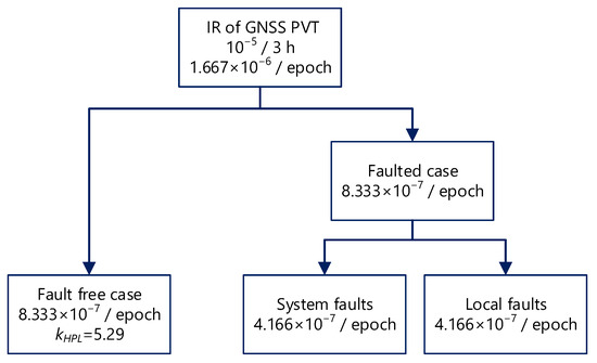
Figure 4.
Integrity fault-tree branch allocating maritime integrity risk (based on [30]).
For a fault free case, if GNSS error-correlation time of 150 s is assumed and treated as integrity epoch correspondingly to aviation standards [22], then a 3 h operation interval recommended by IMO in the resolution A.915(22) will contain 3 × 3600 s/150 s = 72 statistically independent epochs. This gives per-epoch integrity risk probability of:
If IR is relaxed for 15-min operation interval, as proposed by some of maritime experts [30] and fixed in the resolution A.1046(27), then:
The values resulting from (4) and the following (5) have been used for construction of the integrity fault-tree presented in the Figure 4. If IR is further divided evenly into fault free and faulted case, then IR = 8.333 × 10⁻⁷ in either state (5):
Assuming that two-dimensional (2D) positioning data are sampled from a multivariate Gaussian with zero covariance, the sum of squared Gaussian data points is known to be distributed according to a Chi-square distribution. In such a case, to get the fault-free HPL (the faulted cases are identified via health flags or PNT data processing) of confidence corresponding to the probability of 99.99992%, a coverage factor of kHPL ≈ 5.29 should be used as suggested in Figure 4 and explained in Appendix B. In [31], one can also find the detailed algorithm of HPL calculation, using SBAS integrity data, leading to the solution of the Equations (6) and (7).
where:
- σE2 is the estimated variance of the antenna receiver Easting measurement in the local reference frame centered on the GPS antenna (East, North, Up, ENU) (m2);
- σN2 is the estimated variance of antenna receiver Northing measurement in the local reference frame (ENU) (m2);
and the mixed term σEN is the co-variance of respective measurements (m2).
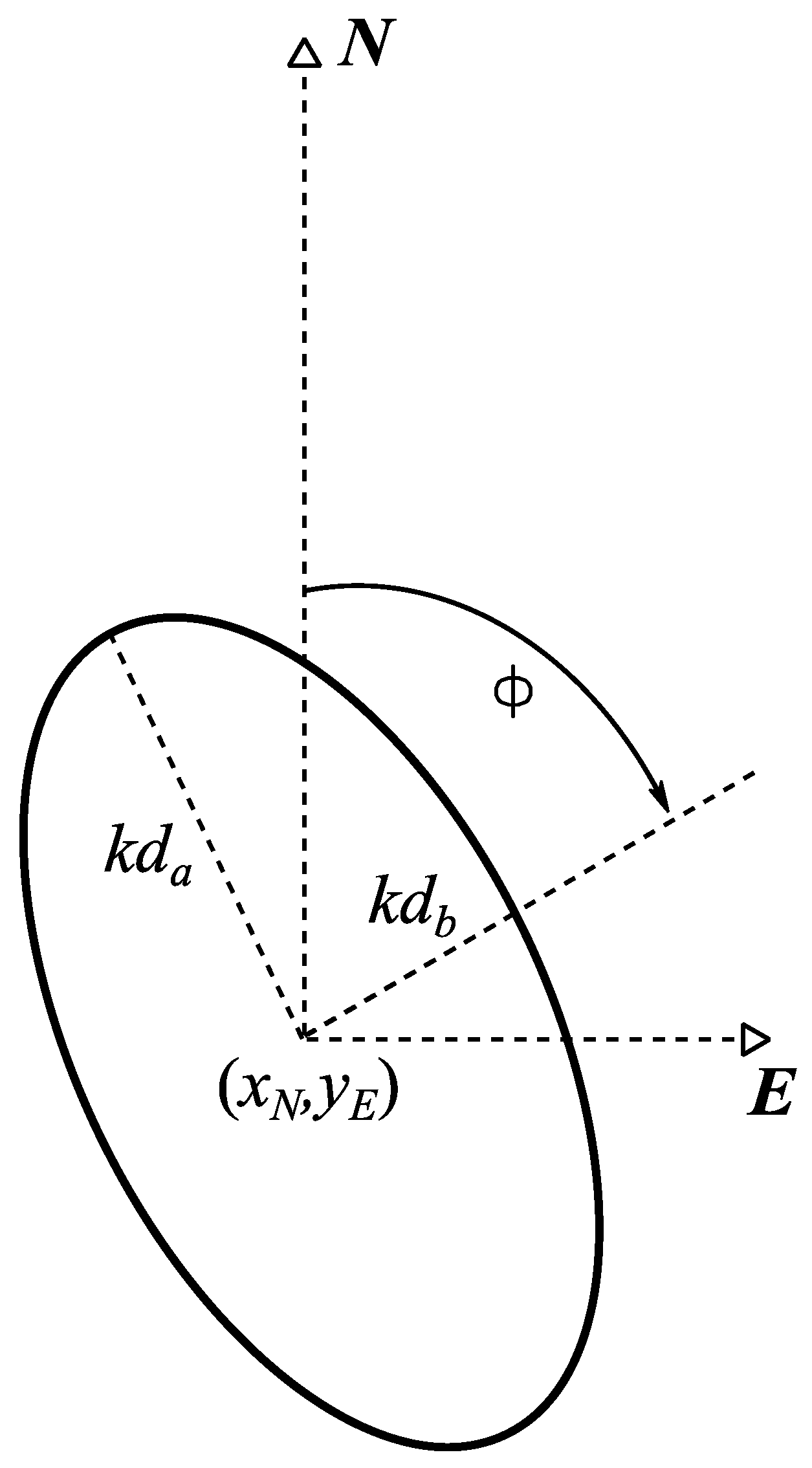
The “elliptical” presentation of a protection level could provide navigators with an extra benefit coming from knowledge of N-E variances and their covariance resulting in changes of the ellipse’s orientation and shape. The algorithm of the GNSS positioning integrity assessment in maritime domain in such a case can be based on the calculation of a protection ellipse (PE) specified by 4 parameters, i.e.: (1) semi-major axis of the estimated 1σ position error ellipse da (m), (2) semi-minor axis of the 1σ error ellipse db (m), (3) orientation of the error ellipse Φ, and (4) coverage factor k (see Figure 5 and (7)).
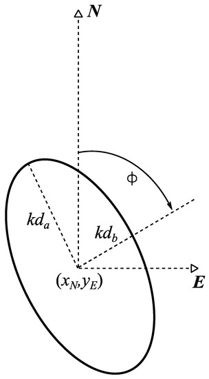
Figure 5.
Elliptical representation of an SBAS based protection area (based on [31]).
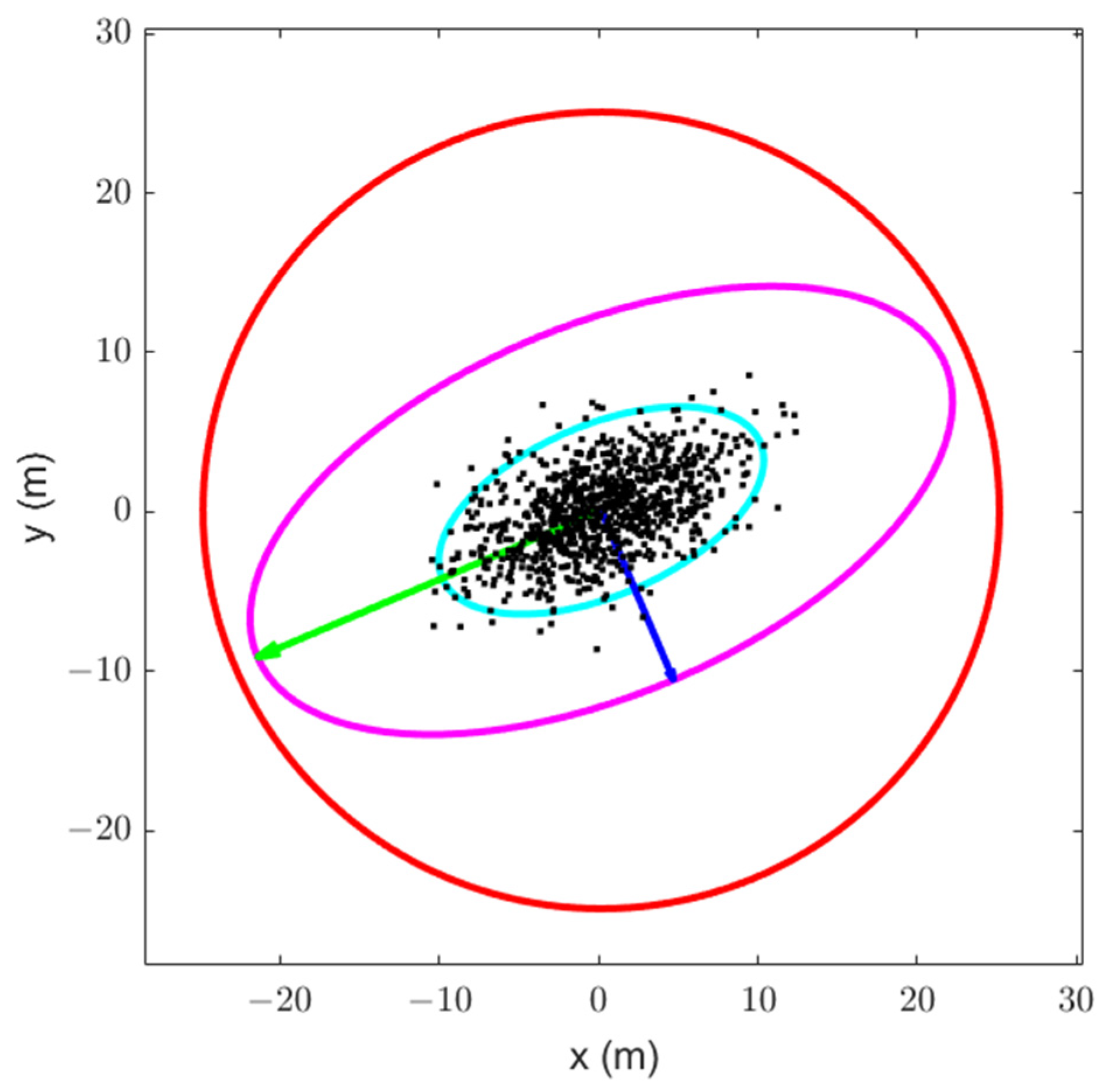
Figure 6 shows an example of 2D horizontal confidence ellipses (PE) for positioning data recorded by a shipborne multi-constellation GNSS receiver in the Baltic Sea. The data consisted of 900 consecutive positions updated every 1 s during 15 min. observation standardized by current IMO regulations. The positions are marked by black dots. The 95% ellipse is marked in cyan color, the 99.99992% or PL ellipse, corresponding to IR in (5), is marked in magenta color, and the 25 m AL circle, corresponding to [13] is marked in red color. The positions coordinates measured in UTM WGS-84 have been shifted relative to their high precision GNSS PPP counterparts fixed at (0,0) coordinates of the adopted ship body-fixed cartesian reference frame of measurements.
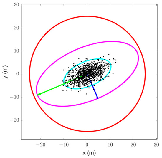
Figure 6.
Example of 2D 95% and 99.99992% confidence ellipses, and AL circle for GNSS recorded data (own study).
It can be noticed in Table 2 that neither GPS nor other GNSS systems such as GLONASS, Galileo, Beidou, and their combined constellation meet the IMO future requirements for satellite navigation without any problems [13]. The sample measurements taken in the Baltic Sea prove that HPL calculated according to (5) or (3) can easily exceed the AL of 25 m. Utilizing more innovative solution of PE, one can expect that protection area dimensions will be several meters lower than HPL but close to AL as well.

Table 2.
Parameters of sample GNSS position data in the Figure 6.
The values of parameters presented in Table 2 are consistent with the GPS SPS position accuracy standards [32] presented in Table 3 and other satellite navigation systems’ single frequency open service standards and IR modeling [33].

Table 3.
SPS position accuracy standards according to [32].
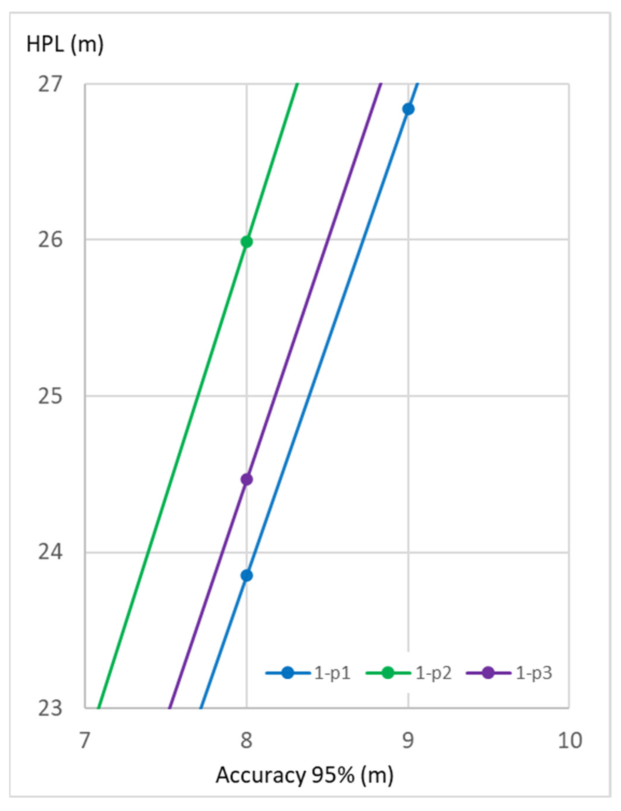
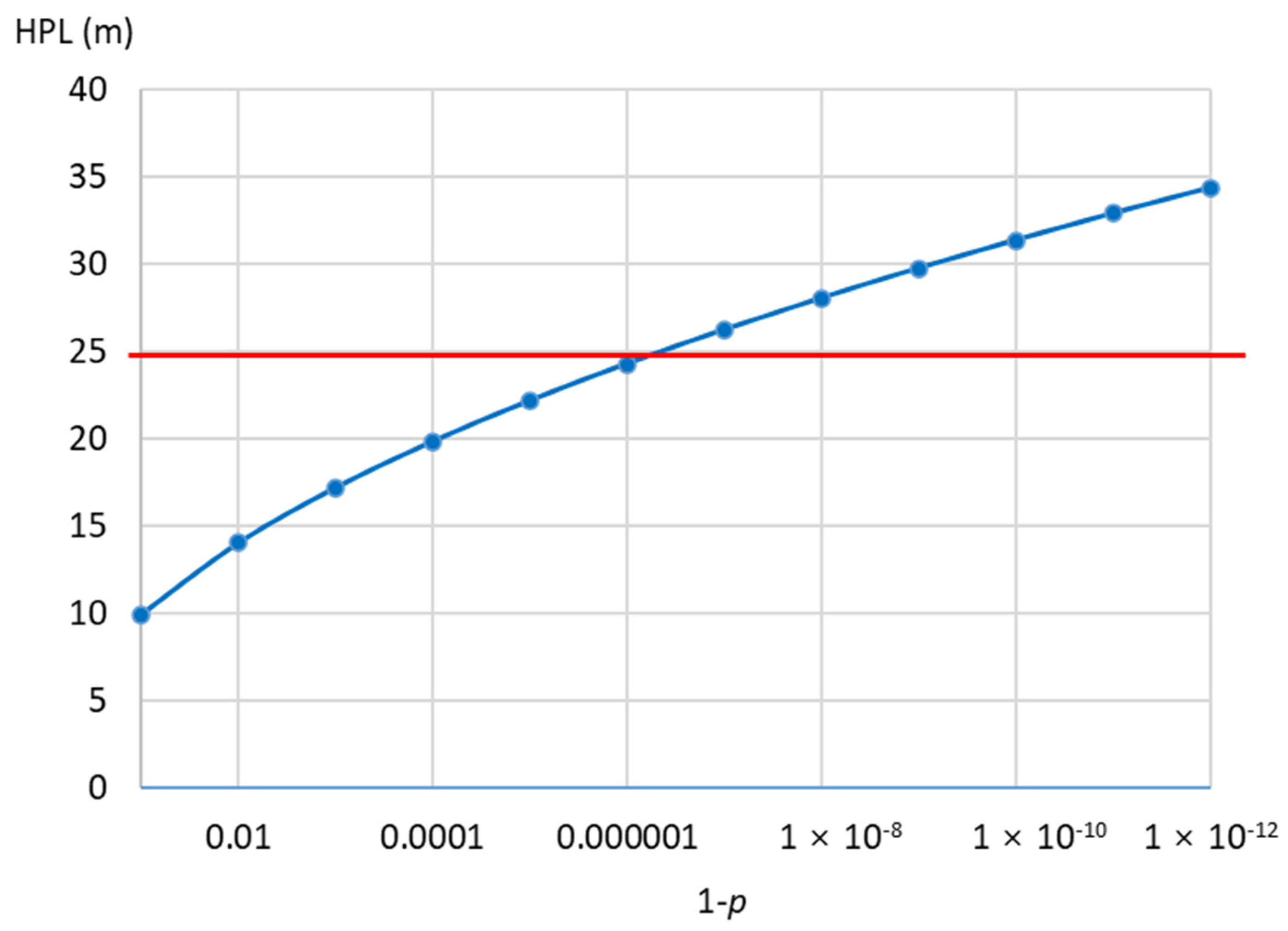
A 95% horizontal error is equivalent to 1.73DRMS (R95), which for 8.55 m can be converted to HPL of 26.16 m. For R95 = 8 m (global average horizontal position accuracy of GPS) [32], HPL = 24.47 m; for R95 = 15 m (the best IMO approved horizontal position accuracy of single frequency GNSS—Galileo [6]), HPL = 45.88 m. Table 4 and Table 5 and corresponding figures show dependence of HPL on 95% accuracy (Figure 7) and dependence of HPL on its probability level p (Figure 8).

Table 4.
Dependence of HPL specified for p on 95% accuracy.

Table 5.
Dependence of HPL specified for 8 m 95% accuracy on its probability level p.
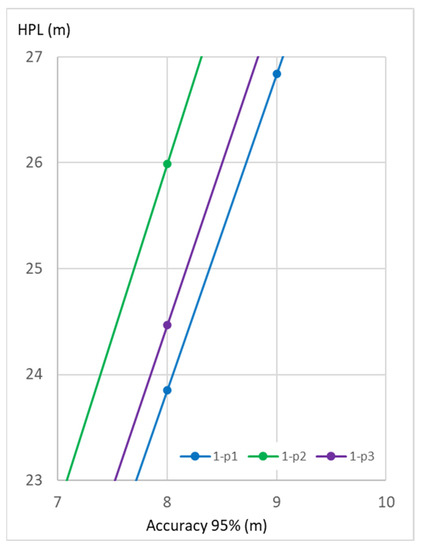
Figure 7.
Dependence of HPL specified for p in Table 4 on 95% accuracy.
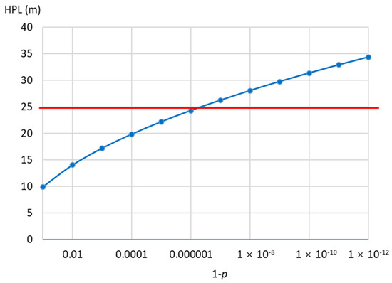
Figure 8.
Dependence of HPL specified for 8 m 95% accuracy on its probability level p (logarithmic scale).
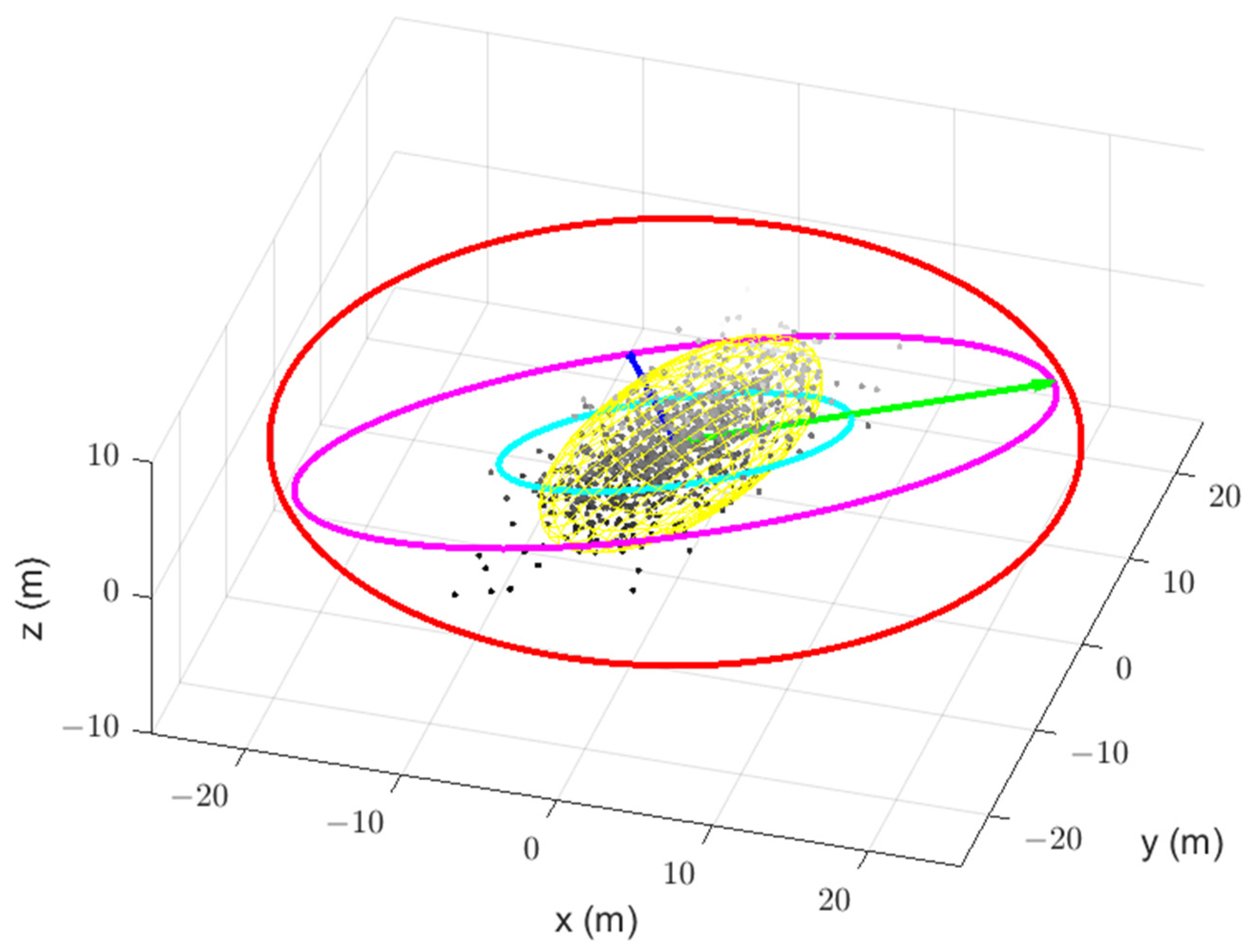
Figure 9 supplements Figure 6 with 3D 95% confidence ellipsoid for positioning data (marked in yellow color). Because nowadays, in many ports, there is a need to estimate a ship’s under keel clearance (UKC) with the accuracy of centimeters, it can be expected that 3D PL usage will soon be applied in maritime domain. Applications of an error ellipsoid in other industrial measurement fields such as 3D laser radar measurement system (LRMS) or ground-based and space-based surveillance were described in [34,35]. Parameters of the data plotted in Figure 9 are presented in Table 6. The positioning data covered another 900 points recorded during 15 min observation.
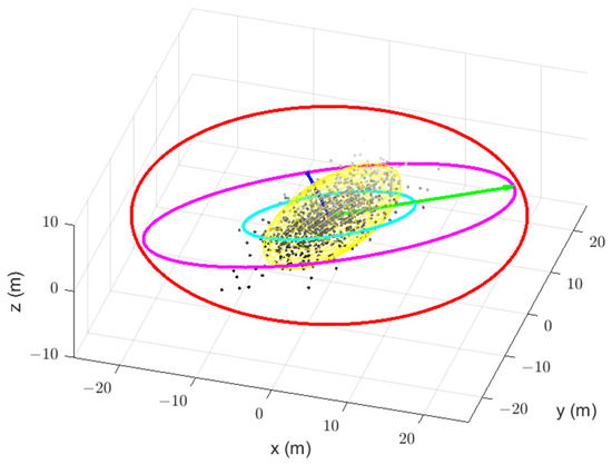
Figure 9.
Example of horizontal 95%, 99.99992% confidence ellipses, AL circle, and 3D 95% confidence ellipsoid for GNSS recorded data (own study).

Table 6.
Parameters of sample GNSS position data in the Figure 9.
It is evident from Table 4, Figure 7, and Table 2 and Table 6 that AL violation for 0.00008% IR can occur if 95% GNSS horizontal error slightly exceeds 8 m, precisely 8.18 m.
Similar to IR, the definitions of continuity and availability in the resolution A.915(22) also give room for questioning as they are time-dependent and availability takes into account the performance of the receiver whose reliability and technical parameters (especially its internal error’s contribution) in such a case should be certified in a similar way as it is done in aviation. The continuity level of 99.97% per 3 h corresponds to a mean time between failures (MTBF) of 10,000 h (8) or almost 417 days while availability level of 99.8% per 30 days corresponds to a downtime (DT) reaching 1.44 h per month or per 720 h (9) that includes failures and integrity alerts:
In [36], a method is presented for determining the navigation system positioning accuracy based on a reliability model where the system’s operation and failure statistics are referred to as life and failure times. It allows for the calculation of the estimated system’s position error with a specific probability more accurately than using the classical approach of DRMS.
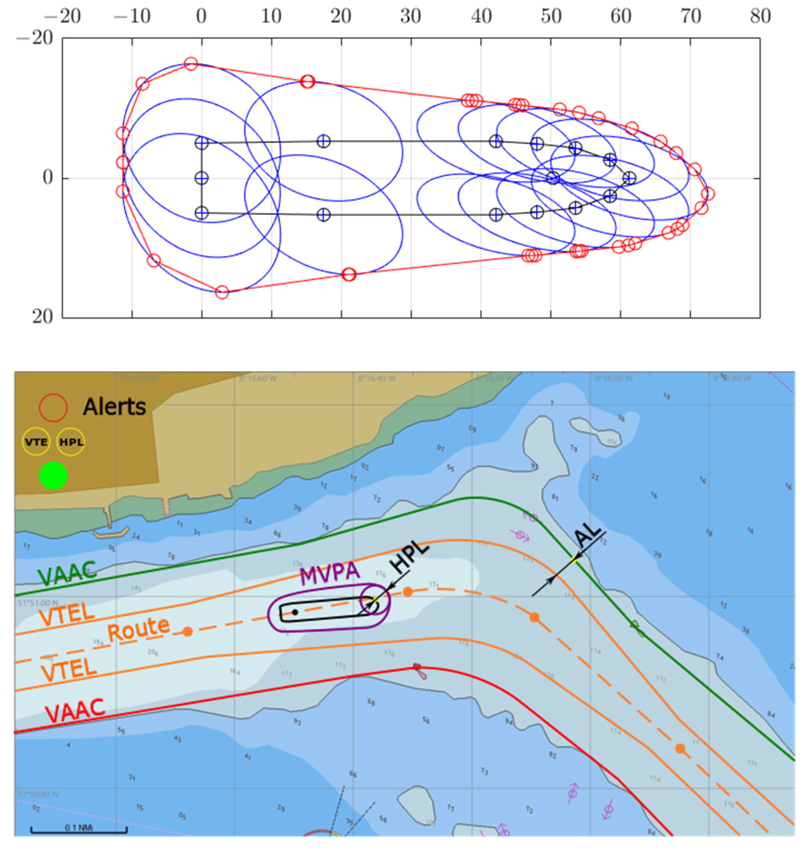
In 2017, a Maritime Vessel Protection Area (MVPA) concept was introduced by the info note to IMO Navigation, Communication, Search, and Rescue Subcommittee [37] and the algorithm of the GNSS positioning integrity assessment based on the calculation of protection ellipses from EGNOS integrity data was presented and subsequently tested in the electronic chart display and information system (ECDIS) designed for maritime autonomous ships’ operators (Figure 10) [31].
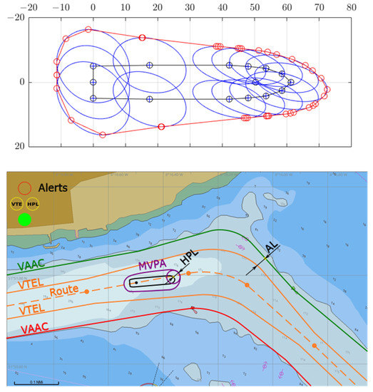
Figure 10.
MVPA construction (top) and its application in ECDIS system (bottom) (based on [31]).
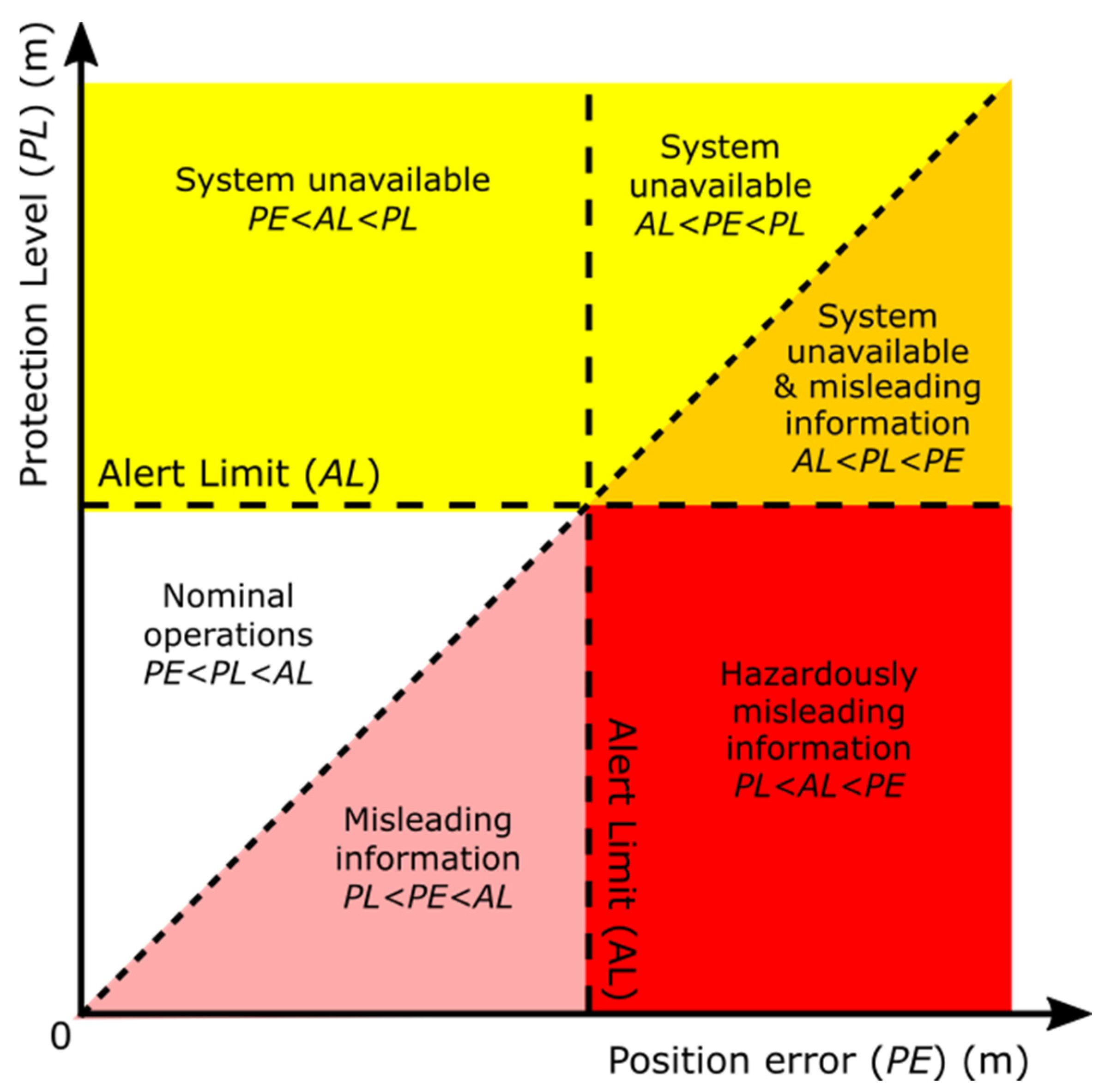
The relations among PL, AL, and true, unknown, position error (PE) could be interpreted by the Stanford-ESA diagram [38] (see Figure 11).
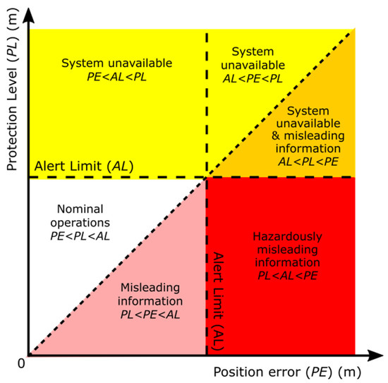
Figure 11.
Interpretation of Stanford diagram based on 4 relations of system availability (based on [38]).
In 2017, the attempt to guide maritime stakeholders through some of PNT integrity issues that emerged in resolution A.915(22) was finalized by adopting the Circular MSC.1/Circ.1575 [14] on Guidelines for Shipborne Position, Navigation and Timing Data Processing (PNT DP). This circular recommends in a generic way how PNT integrity should be monitored in the maritime PNT equipment but without providing any specific algorithms as required by ICAO and RTCA for aviation [22].
According to MSC.1/Circ.1575, firstly, methods and thresholds used by the PNT DP for integrity monitoring should be qualified to evaluate if the supported accuracy level of PNT output data has been achieved or not. Therefore, the accuracy level was proposed as intra-system AL or threshold value that differentiates between fulfilled and failed requirements on PNT data output. Secondly, the TTA should be the tolerated time span for accuracy evaluation by the PNT DP. Thirdly, it is recommended to manufacturers to predetermine the IR of the applied integrity monitoring methods, taking into account application-relevant time periods under nominal conditions, if practicable. If the PNT-DP supports a redundant provision of PNT and integrity data in relation to the same accuracy level, the IR should be pre-evaluated for application-relevant time periods and provided as configuration parameter to ensure that the most reliable PNT data are selected for output. MSC.1/Circ.1575 also proposed some concepts of:
- (1)
- Consistency tests using two sensors or model of ship’s movement.
- (2)
- Determination of PL by RAIM using such tests.
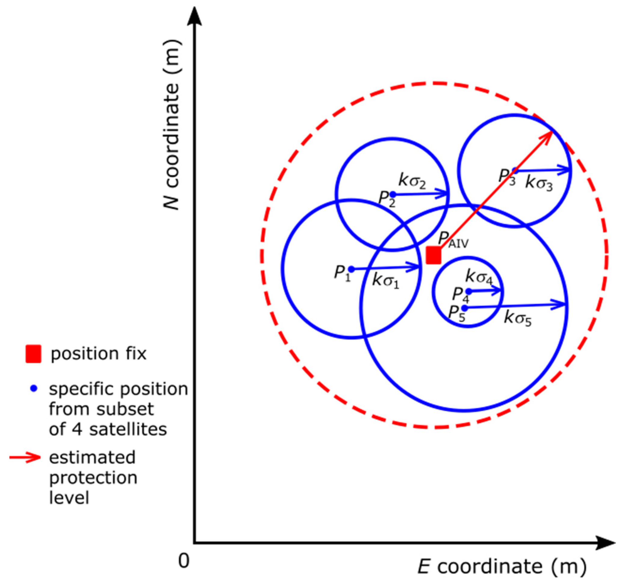
For example, if from 6 satellites in view only 5 measured pseudo-ranges had passed the consistency tests, then 6 position solutions could be determined with the 5 consistent pseudo-ranges: the all-in-view solution (PAIV) of 5 pseudo-ranges and the five solutions achieved with any subset of 4 pseudo-ranges. The position error per solution would depend on the expected standard deviation of position error (DOP based projection of expected standard deviation of ranging errors in the position domain) and a coverage factor k. The largest distance of an estimated position error (for example, kσ3 of the 3rd position solution P3) to the PAIV would be determined as an HPL (10) (see Figure 12).
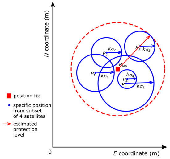
Figure 12.
Determination of HPL by high level RAIM (based on [14]).
The use of SBAS corrections in maritime receivers is currently not regulated. Two possible strategies for a development of a dedicated standard based on the operational requirements specified by IMO for a component of WWRNS and for future GNSS, respectively, were discussed in [39]. Further research is necessary on GNSS multipath modeling, jamming, spoofing [40], and the impact of solar activity in marine environment. Promising results are achieved via multi-GNSS multipath error mitigation [41] or quantification of solar activity effect (expressed by sunspots) using fuzzy logic [42].
Another route to the future maritime GNSS performance standards leads through the experience gained in domain of offshore and dynamic positioning (DP) [43] and multi sensor fusion as researched in autonomous cars [44].
The DP control system may receive position fixes from several position reference systems. The relevant position information is extracted from each input by means of a dedicated input card or program block for each particular position reference. To account for the different antenna positions, etc., fixed offsets are applied to each position fix in order to reference them to a common point (the vessel’s control point). After extracting the position information, each fix is treated in a similar manner. Various checks are performed on each position fix. As a minimum, these checks test for excessive changes of position (typically greater than 5 m) and ‘frozen’ position (typically changes of less than 0.1 m). If any position reference repeatedly fails any of these tests for a period of time (e.g., 10 s), then it is automatically be rejected by the DP control system. Having failed, it will not become available for selection again until it has satisfied the various test conditions for a similar period of time. All position fixes accepted by the DP control system are combined into a best position fix. The method weights each position reference system according to recent performance similarly to IMO proposals of consistency tests described in Section 2 (Figure 12) [14]. Alternatively, all position fixes may be weighted equally or they may be voted so the median is used. Since the DP control system performs its own filtering of position fixes and performs position/velocity estimates on these filtered signals, all position reference systems should provide raw data. With improved sensors and time-tagging, there are developments of fused GNSS/INS (inertial navigation system).
With three or more position references, it is possible for the DP control system to compare positioning systems independent of the estimated position. If one of the references is subject to drift or instability, it can be seen to be changing relative to the other two ‘correct’ references. If there is disagreement in positions when using two position references, it is difficult to identify which one is at fault. With only one reference, it is difficult to determine the performance of the system unless there is a quality indicator. Table 7 presents quality indicators recommended by IMCA (International Marine Contractors Association) [43]:

Table 7.
GNSS quality indicators as proposed by IMCA (based on [43]).
A DP vessel which becomes a predecessor of a future maritime autonomous surface ship (MASS) rarely uses only one position reference: two, three, and even four are often used simultaneously. Thus, there is generally system redundancy and the design intent within the DP control system is that the failure of any one position reference should have little effect on the station-keeping performance. The redundancy of GNSS reception equipment and other positioning systems is obligatory in DP class 2 or 3 vessels. This is achieved firstly by the provision of other position references and, secondly, by the DP control system’s predicted mathematical model derived from recent performance. The model is a last resort if all position references are unavailable. Where there are two DGNSS systems onboard a DP vessel, they should both be available on-line in order to provide continuous cross-checking for integrity monitoring. Steps should be taken where possible to give independence between the solutions, such as use of different reference stations, correction links, hardware, and software. Cross-checking is particularly important as true calibrations can only be done when there is a more accurate reference against which to calibrate. Therefore, comparisons are done with other systems, usually by plotting excursions with DGNSS in and out of the DP control system. In a hypothetical situation where DGNSS and position references from other GNSS independent sources such as acoustics, laser, radar, and taut wire deteriorate simultaneously and are all marginal for DP acceptance, the GNSS should be suspected first. This is rationalized by its technical complexity and greater number of potential failures than in simpler systems.
The room for negotiations, verification, and update of IMO GNSS performance standards emerged in 2020 when IMO commenced work on functional approach and modular structure for performance standards for shipborne satellite navigation system receiver equipment providing position, navigation, and time data and associated information [45]. The applicability of the proposed approach is to be proven by the exemplary implementation of a performance standard for shipborne Quasi-Zenith Satellite System (QZSS), BeiDou Navigation Satellite System (BDS), and Galileo receiver equipment. During its 7th session, the IMO Sub-Committee on Navigation, Communications, And Search And Rescue (NCSR) agreed that the work on the development of generic performance standards for shipborne satellite navigation system receiver equipment should continue in the context of “satellite” navigation receiver equipment only and, in this respect, invited interested parties to progress the work inter-sessionally and submit relevant proposals to NCSR 8 for finalization. At the 8th session of NCSR, a proposal was submitted by China, Germany, and Poland (NCSR 8/4/1). At the same session, Australia and New Zealand submitted a paper to include SBAS in that work item. NCSR 8 then agreed to establish an official correspondence group (CG), chaired by Germany, to “finalize a draft MSC resolution on generic performance standards for shipborne satellite navigation system receiver equipment, addressing, in particular, the relationship with existing performance standards already adopted by the Organization”. The inclusion of SBAS was not accepted as part of the Terms of Reference for the CG. The CG submitted a finalized document to NCSR 9, but due to time constrains given the set-up as online meeting with reduced working hours, the paper was not discussed but put forward to next session of NCSR (NCSR 10) in 2022.
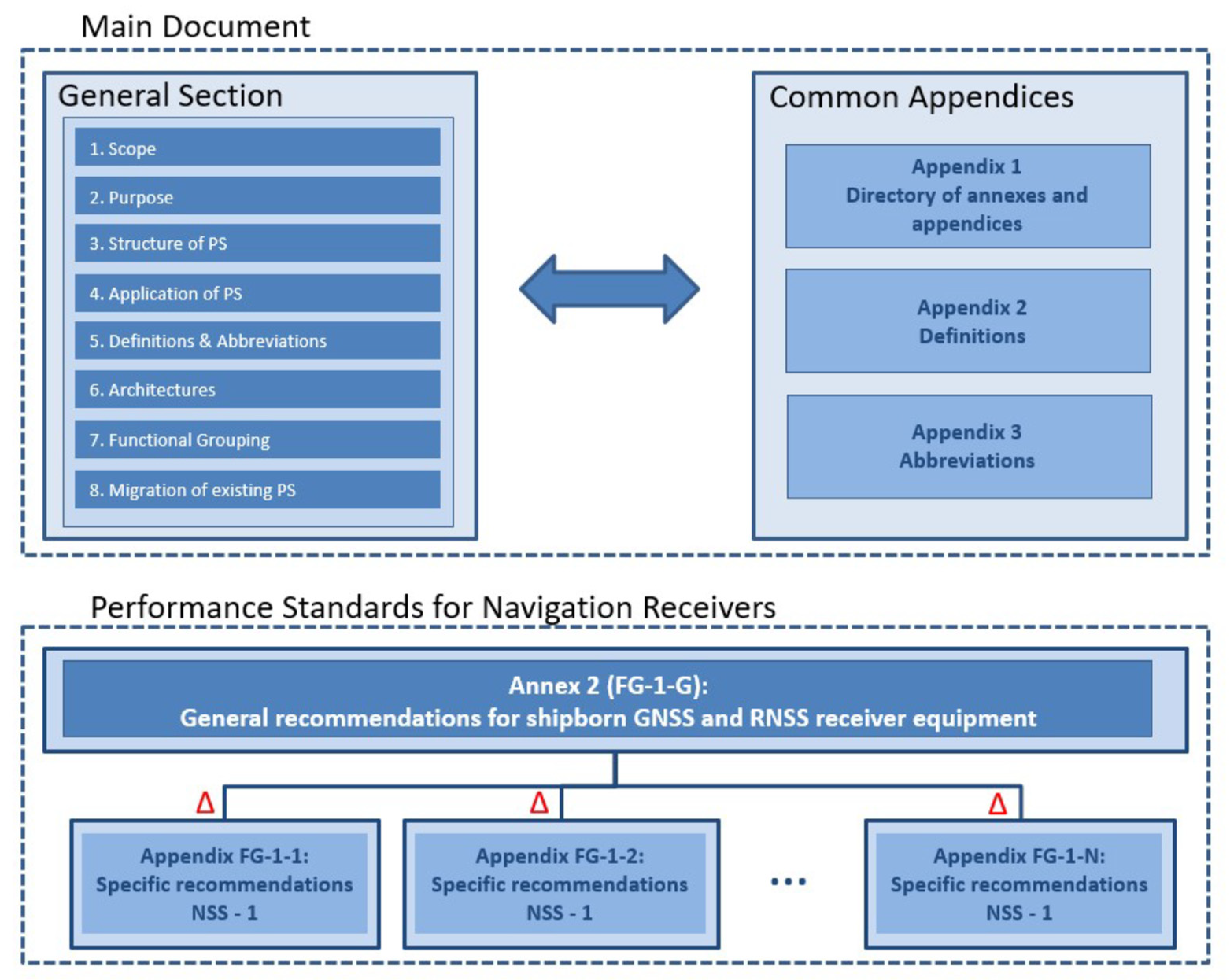
The Report of the CG [45] includes a new draft MSC Resolution “Recommendation on consolidated performance standards for future adoption of new and amendment of existing shipborne satellite navigation system receiver equipment”. This document suggests one standard for all GNSS and RNSS shipborne receivers. It is structured into the “Main Document”, including all general information, such as scope, purpose, structure, and application of the Performance Standards, and other sections, followed by the Annex 2, which includes the performance standard as such (as shown in the Figure 13). Annex 2 starts with section “FG-2-G” with all recommendations applicable for all GNSS and RNSS receivers. For each specific system, an additional appendix (Appendix FG-1-1 to FG-1-X) is added, including the system specific recommendations. For illustration purposes, the document includes appendices FG-1-1 (QZSS), FG-1-2 (Galileo) and FG-1-3 (BEIDOU).
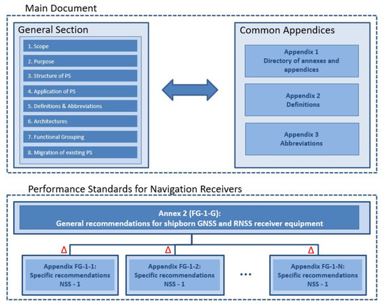
Figure 13.
Structure of the IMO generic GNSS performance standards (based on [45]).
It is suggested that the existing single standards will stay in force until the respective system is included in the generic standard by adopting a new specific recommendation (FG-1-X) to the generic standard. In this way, over time, the single standards will be removed and the systems will be covered by the generic performance standard.
The CG has also worked on SBAS and prepared a suggestion on how to include SBAS systems (e.g., WAAS, EGNOS) as additional annexes to this generic performance standard. It is expected that there will be an input paper for MSC 107 in spring 2023 to get IMO approval for official work on this topic.
5. Discussion
The two IMO resolutions, A.1046(27) and A.915(22), form the background of IMO’s present and future requirements for Maritime GNSS. Res. A.1046(27) gives the formal requirements and procedures for accepting new systems as components of the World-Wide Radionavigation System (WWRNS), while Res. A.915(22) is a document suggesting IMO requirements for future developments of GNSS to be considered within the framework of A.1046(27), as amended. There are numerous challenges to achieve electronic position fixing integrity, continuity, and availability level as envisioned by IMO in A.915(22). Regionally in the European Union, the European Radionavigation Plan was developed in 2018 [33] to deal with these challenges and threats from jamming or spoofing of GNSS signals.
The first challenge is the necessary improvement of GNSS system parameters or IMO recognition of SBAS and LEO PNT to meet specific requirements of Res. A.915(22). The most important issue is the consent of maritime stakeholders to the integrity assessment time. Dimensions of PL are related to this time, so the suggested 3 h or 15 min is a very demanding requirement after conversion to an independent position measurement performed every 1 s. The problem of coverage factor for PL determination and utilization of a protection ellipse or MVPA needs further research and users’ consultation as well. The other issue is the predictive and reactive nature of GNSS integrity augmentation addressed in aviation concepts [20]. Maritime systems should also have:
- (a)
- a predictive annunciation that the GNSS data delivered to the shipborne system is going to exceed the required navigation performance thresholds specified for the current and planned operational tasks (GNSS alert status),
- (b)
- a reactive annunciation that the GNSS data delivered to the shipborne system has exceeded the required navigation performance thresholds specified for the current operational task (GNSS fault status),
- (c)
- in case of predictive annunciation, a fixed minimum time allowed for the caution flag to be provided to the user before the onset of a GNSS fault resulting in an unsafe condition,
- (d)
- in case of reactive annunciation, the maximum time allowed from the moment a GNSS fault resulting in an unsafe condition is detected to the moment that the shipborne system provides a warning flag to the user.
Up until now, the issue of predictive alerts has not been dealt with by the maritime community. Research presented in [25] shows clearly that predictive alert announced even 6 min before an unsafe GNSS condition could be very advantageous.
The second challenge is the provision of resilient PNT where terrestrial radio signals as well as shipborne components are necessary in addition to GNSS. Some consider eLoran the ideal back up to GNSS and promote it at the IMO. However, the choice is challenged by the lack of international agreement and by high costs for reactivation and maintenance of infrastructures. R-Mode is also a promising technological approach to be tested out further in near future [46,47].
Another challenge is DGNSS infrastructure improvement. Maintaining and improving the IALA DGNSS service reliability by increasing the number of reference stations to enlarge the area where the user can receive differential corrections implies significant investment and maintenance cost. Potential SBAS based solutions applied over Aids to Navigation (DGNSS and AIS signals) as described in the Guideline G1129 [48] could provide some room for the rationalization of the infrastructure and address the current limitations of legacy DGNSS systems paving the way to the uptake EGNOS services. The main problem is the limited uptake of SBAS-enabled shipborne receivers. There is no maritime standard or guidelines for the implementation of SBAS in shipborne receivers and the majority of these implementations do not take into account the information related to the system integrity messages that the SBAS system broadcasts. Work is ongoing to develop receiver implementation guidelines for EGNOS maritime receivers in Radio Technical Commission for Maritime Services (RTCM), and receivers that fulfil these guidelines [30]. The background is to have EGNOS implemented in a similar way in all receivers to have optimal benefit from the system. The challenge is to ensure an appropriate integration of SBAS in shipborne receivers that would contribute to improve the accuracy and the reliability of the positioning information, which at the end, is one of the main factors to guarantee the safety of life at sea. Work is also ongoing to define a potential maritime SoL service implementation in the upcoming EGNOS v3 system [28]. This new service might also include a more mature integrity implementation than we have in EGNOS or other SBAS today and finally reach users widely.
Similar challenges await inland waterway navigation. Navigation in inland waterways requires position accuracy, including the vertical domain, used to calculate clearance of bridges, locks, etc., and to monitor traffic situation. To increase the performance of GNSS, IALA DGPS stations have been established to some extent also to cover the inland waterways. In addition to this, distribution of DGPS data is also done in some areas with the help of inland AIS base stations, available to vessels that are equipped with an inland AIS transponder (which is compatible with the maritime AIS transponder). In comparison with maritime navigation, inland navigation faces more difficulties related to shadowing and blocking of satellites due to land shadowing, mountains or obstructions from man-made objects. Typical examples are multipath or high DOP. The inland navigators would therefore benefit from multi-constellation navigation, because more satellites are visible and available. There are also reasons to believe that these users could benefit from the High Accuracy Service from Galileo and future dedicated EGNOS services for maritime use.
Compatibility, concerning in particular interfaces and communication links, may enhance the uptake of innovative surveying techniques and expand them to new segments of application. The need for interoperability among devices provided by different manufacturers is also of key importance. Now, many different DGNSS/RTK data formats are available (e.g., RTCM, CMR, etc. [49]), making the use of data coming from various sources and devices quite challenging. Typically, different brands have different levels of interoperability when it comes to receiving augmentation corrections from systems considered as competitors.
Potential solutions to the presented challenges are:
- (1)
- building awareness of maritime community on operation specific GNSS availability, continuity and integrity,
- (2)
- recognition of SBAS by IMO and preparation of standards in a similar way as minimum operational performance standards in aviation [19,22],
- (3)
- approving recommended algorithms of maritime 2D and 3D protection levels,
- (4)
- further standardization of maritime GNSS receivers in scope of supported data formats and interoperability,
- (5)
- utilization of VHF Data Exchange System (VDES) evolving on AIS for augmentation,
- (6)
- utilization of GNSS services going beyond open ones, for instance Galileo Safety of Life or High Accuracy services,
- (7)
- fusion of GNSS data with INS positioning and attitude sensors,
- (8)
- fusion of GNSS data with ship accurate hydrodynamic model.
The last solution is becoming common in relatively rare maritime systems evolving from DP systems (for example, control systems of cruise ships and ferries). Such an approach is very promising in case of necessary TSE reduction, prediction of ship’s motion, or emergency situations where no GNSS data is available.
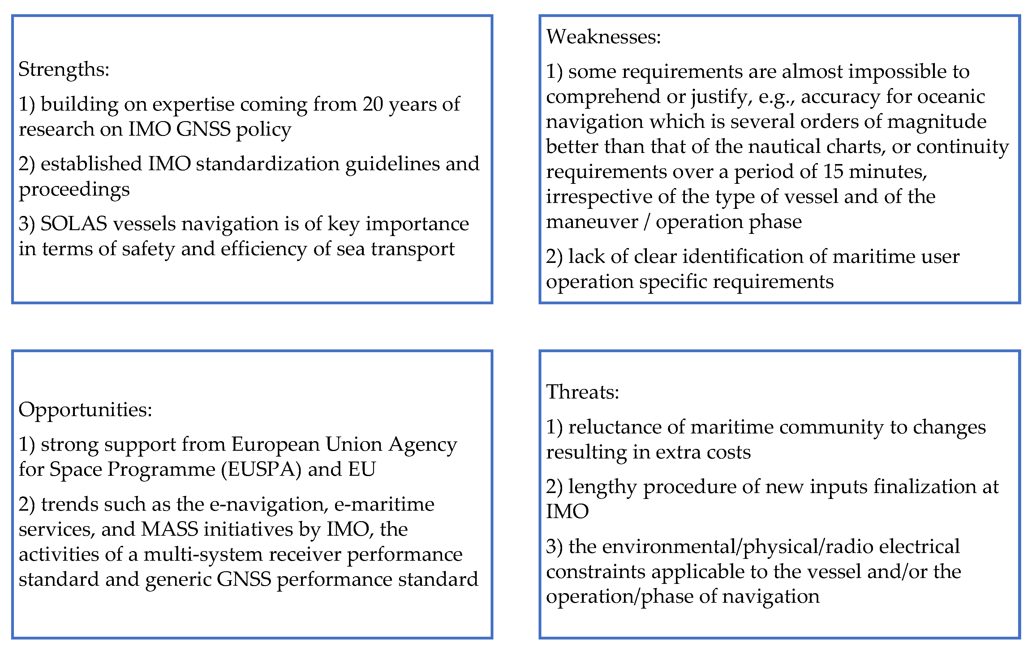
To outline some of the strengths, weaknesses, opportunities, and threats awaiting maritime GNSS standardization process, a SWOT analysis is presented in Figure 14.
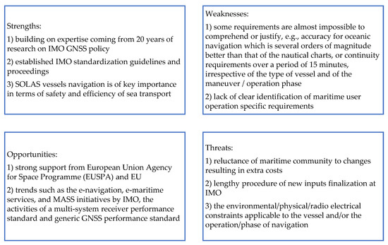
Figure 14.
SWOT analysis of maritime GNSS standardization process.
6. Conclusions
Considering the use of GNSS for maritime navigation, recreational and leisure navigation is overall the largest application. The SOLAS vessels navigation is smaller in terms of market size, but of key importance in terms of safety and efficiency of maritime transport. IMO regulations have a strong role in defining user requirements and represents a key driver for the adoption of new solutions for navigation and positioning, including satellite-based systems and services. The evolution of IMO GNSS and RNSS standards shows that many problems that have already been dealt in other means of transportation, such as aviation, are still to be solved in maritime domain. Therefore, the parameters of GNSS data received by remote sensing from shipborne receivers can be worse than expected for safety and security of maritime activities. Moreover, standards for availability, continuity and integrity of maritime GNSS data are confusing as the two major IMO resolutions on the subject are not fully consistent. The way to reconcile them is to consider that one applies for current requirements (A.1046) [12] while the other deals with possible future requirements (A.915) [13]. The research on detailed solutions is ongoing and some substantial examples have been discussed in this paper followed by SWOT analysis of maritime GNSS standardization process.
Author Contributions
Conceptualization, P.Z.; methodology, P.Z. and M.B.; software, P.Z. and A.B.; validation, A.B. and M.B.; formal analysis, M.B. and P.Z.; investigation, P.Z. and M.B.; resources, A.B., M.B. and P.Z.; data curation, A.B.; writing—original draft preparation, P.Z.; writing—review and editing, A.B. and M.B.; visualization, P.Z.; supervision, M.B.; funding acquisition, P.Z. and A.B. All authors have read and agreed to the published version of the manuscript.
Funding
This study received no external funding.
Acknowledgments
The Authors wish to thank Polish and German IMO NCSR CG Members who participated in the development of IMO GNSS Generic Performance Standards.
Conflicts of Interest
The authors declare no conflict of interest.
Appendix A

Table A1.
Table of abbreviations and acronyms used in the paper.
Table A1.
Table of abbreviations and acronyms used in the paper.
| Abbreviation or Acronym | Definition |
|---|---|
| AIS | Automatic Identification System |
| AIV | All in View |
| AL | Alert Limit |
| ATE | Along Track Error |
| BDS | Chinese GNSS Beidou |
| CAIM | Craft Autonomous Integrity Monitoring |
| CCRP | Common Consistent Reference Point |
| CE | Chart Error |
| CG | Correspondence Group |
| DGLONASS | Differential GLONASS |
| DGPS | Differential GPS |
| DoF | Degrees of Freedom |
| DOP | Dilution of Precision |
| DP | Dynamic Positioning |
| DRMS | Distance Root Mean Squared |
| ECDIS | Electronic Chart Display & Information System |
| EGNOS | European Geostationary Navigation Overlay System |
| ENU | East, North, Up Reference |
| EU | European Union |
| Galileo | European GNSS |
| GBAS | Ground Based Augmentation System |
| GLONASS | Russian GNSS |
| GNSS | Global Navigation Satellite System |
| GPS | US Global Positioning System |
| HAL | Horizontal Alert Limit |
| HDOP | Horizontal Dilution of Precision |
| HPL | Horizontal Protection Level |
| IALA | International Association of Marine Aids to Navigation and Lighthouse Authorities |
| ICAO | UN International Civil Aviation Organization |
| IMO | UN International Maritime Organization |
| IR | Integrity Risk |
| LEO | Low Earth Orbit |
| LPME | Line of Position Mean Error |
| MDB | Marginally Detectable Bias |
| MDE | Marginally Detectable Error |
| MSC | IMO Maritime Safety Committee |
| MSI | Maritime Safety Information |
| MVPA | Maritime Vessel Protection Area |
| NCSR | IMO Navigation, Communication, and Search & Rescue Subcommittee |
| NSE | Navigation System Error |
| PDOP | Position Dilution of Precision |
| PE | Position Estimate / Error or Protection Ellipse |
| PL | Protection Level |
| PNT | Position, Navigation, Timing |
| PNT DP | PNT Data Processing |
| PPP | Precise Point Positioning |
| QZSS | Japanese Quasi Zenith Satellite System |
| RAIM | Receiver Autonomous Integrity Monitoring |
| RF | Radio Frequency |
| RNSS | Regional Navigation Satellite System |
| RTCA | Radio Technical Commission for Aeronautics |
| RTCM | Radio Technical Commission for Maritime Services |
| RTK | Real Time Kinematics |
| SBAS | Satellite Based Augmentation System |
| SOLAS | IMO Convention on Safety of Life at Sea |
| SV | Satellite Vehicle |
| SWOT | Analysis of Strengths, Weaknesses, Opportunities, Threats |
| TSE | Total System Error |
| TTA | Time to Alarm |
| UN | United Nations |
| VDES | VHF Data Exchange System |
| VHF | Very High Frequency |
| VTE | Vessel Technical Error |
| VTS | Vessel Traffic Services |
| WAAS | US Wide Area Augmentation System |
| WWRNS | Worldwide Radionavigation System |
| XTE | Cross Track Error |
Appendix B
Current models of coverage factor for PL and PE determination are based on the equation of an error ellipse aligned with the coordinate axes x, y:
where s defines the scale of the ellipse and could be any arbitrary number representing a chosen confidence level and the lengths of the ellipse’s axes are defined by the standard deviations σx and σy of the data.
Assuming that 2D positioning data are sampled from a multivariate Gaussian with zero covariance means that both the x-values and the y-values are normally distributed. Therefore, the lefthand side of Equation (A1) actually represents the sum of squares of normally distributed independent data samples. The sum of squared Gaussian data points is known to be distributed according to a Chi-square distribution defined in terms of “degrees of freedom” (DoF), which represent the number of unknowns. In a bi-dimensional case, there are two unknowns and 2-DoF. Therefore, the probability of the sum (A1) is less than or equal to a specific value obtained from the cumulative Chi-square 2-DoF (n = 2) distribution or in other words cumulative Rayleigh distribution. In the 2-DoF Chi-square case, a 95% confidence interval corresponds to s ≈ 5.991. The axis-aligned error ellipse can therefore be drawn as an ellipse with semi-axes lengths a, b equal to:
In real cases where the 2D data are not uncorrelated, a covariance different from 0 exists and the resulting error ellipse will not be axis-aligned. Therefore, the variances parallel to the directions in which the data vary the most need to be calculated. The lengths of major and minor axis of the confidence ellipse will depend on these variances. In the case of correlated data, the eigenvalues represent these variances and the data eigenvectors represent the direction of the largest spread of the data. The 95% confidence ellipse can be defined in such a case similarly to the axis-aligned case, with the major axis of length given by (A3):
where:
- λa and λb represent the eigenvalues of the covariance matrix.
To obtain the orientation of the ellipse Φ, the angle of the largest eigenvector towards the x-axis should be calculated according to (A4):
where:
- vλ
- represents the eigenvector of the covariance matrix that corresponds to the largest eigenvalue of x and y coordinate respectively.
Assuming that 3D positioning data are sampled from a multivariate Gaussian, the k-factor can be obtained from the cumulative Chi-square 3-DoF (n = 3) distribution or the cumulative Maxwell distribution. Other parameters of the ellipsoid’s semi-axes lengths a, b, c and orientation in x-z or y-z plane can be obtained according to formulae analogous to (A3) and (A4).
References
- IMO. A.666(16), World Wide Radionavigation System; International Maritime Organization: London, UK, 1989. [Google Scholar]
- IMO. MSC.112(73), Adoption of the Revised Performance Standards for Shipborne Global Positioning System (GPS) Receiver Equipment; International Maritime Organization: London, UK, 2000. [Google Scholar]
- IMO. MSC.113(73), Adoption of the Revised Performance Standards for Shipborne GLONASS Receiver Equipment; International Maritime Organization: London, UK, 2000. [Google Scholar]
- IMO. MSC.114(73), Adoption of the Revised Performance Standards for Shipborne DGPS and DGLONASS Maritime Radio Beacon Receiver Equipment; International Maritime Organization: London, UK, 2000. [Google Scholar]
- IMO. MSC.115(73), Adoption of the Revised Performance Standards for Shipborne Combined GPS/GLONASS Receiver Equipment; International Maritime Organization: London, UK, 2000. [Google Scholar]
- IMO. MSC.233(82), Adoption of the Performance Standards for Shipborne Galileo Receiver Equipment; International Maritime Organization: London, UK, 2006. [Google Scholar]
- IMO. MSC.379(93), Performance Standards for Shipborne Beidou Satellite Navigation System (BDS) Receiver Equipment; International Maritime Organization: London, UK, 2014. [Google Scholar]
- IMO. MSC.401(95), Performance Standards for Multi-System Shipborne Radionavigation Receivers; International Maritime Organization: London, UK, 2015. [Google Scholar]
- IMO. MSC.432(98), Amendments to Performance Standards for Multi-System Shipborne Radionavigation Receivers (RESOLUTION MSC.401(95)); International Maritime Organization: London, UK, 2017. [Google Scholar]
- IMO. MSC.449(99), Performance Standards for Shipborne Indian Regional Navigation Satellite System (IRNSS) Receiver Equipment; International Maritime Organization: London, UK, 2018. [Google Scholar]
- IMO. MSC.480(102), Performance Standards for Shipborne Japanese Quasi-Zenith Satellite System (QZSS) Receiver Equipment; International Maritime Organization: London, UK, 2020. [Google Scholar]
- IMO. A.1046(27), World Wide Radionavigation System; International Maritime Organization: London, UK, 2011. [Google Scholar]
- IMO. A.915(22), Revised Maritime Policy and Requirements for A Future GNSS; International Maritime Organization: London, UK, 2001. [Google Scholar]
- IMO. MSC.1/Circ.1575, Guidelines for Shipborne Position, Navigation and Timing (PNT) Data Processing; International Maritime Organization: London, UK, 2017. [Google Scholar]
- IMO. A.860(20), Maritime Policy for A Future Global Navigation Satellite System (GNSS); International Maritime Organization: London, UK, 1997. [Google Scholar]
- RTCM. RTCM 10403.3, Differential GNSS (Global Navigation Satellite Systems) Services-Version 3 + Amendment 3; Radio Technical Commission for Maritime Services: Washington, DC, USA, 2021; Available online: https://rtcm.myshopify.com/products/rtcm-10403-3-differential-gnss-global-navigation-satellite-systems-services-version-3-amendment-2-may-20-2021?_pos=2&_sid=4b86b96f6&_ss=r (accessed on 19 October 2022).
- Walter, T.; Blanch, J.; Choi, M.J.; Reid, T.; Enge, P. Incorporating GLONASS into Aviation RAIM Receivers. In Proceedings of the 2013 International Technical Meeting of The Institute of Navigation, San Diego, CA, USA, 27–29 January 2013; pp. 239–249. [Google Scholar]
- Teunissen, P.J.G.; Imparato, D.; Tiberius, C.C.J.M. Does RAIM with Correct Exclusion Produce Unbiased Positions? Sensors 2017, 17, 1508. [Google Scholar] [CrossRef] [PubMed]
- ICAO. Standards and Recommended Practices (SARPs), Volume 1–Annex 10, Amendments 1-81; International Civil Aviation Organization: Montreal, Canada, 2006. [Google Scholar]
- Sabatini, R.; Moore, T. A New Avionics-Based GNSS Integrity Augmentation System: Part 1–Fundamentals. J. Navig. 2013, 66, 363–384. [Google Scholar] [CrossRef]
- Sabatini RMoore, T.; Hill, C. A New Avionics-Based GNSS Integrity Augmentation System: Part 2–Integrity Flags. J. Navig. 2013, 66, 501–522. [Google Scholar] [CrossRef]
- RTCA. Minimum Operational Performance Standards for Global Positioning System/Satellite-Based Augmentation System Airborne Equipment. DO-229E, SC-159; Radio Technical Commission for Aeronautics: Washington, DC, USA, 2016; Available online: https://my.rtca.org/productdetails?id=a1B3600000211rIEAQ (accessed on 19 October 2022).
- IEC. Maritime Navigation and Radio-communication Equipment and Systems–Global Navigation Satellite Systems (GNSS)–Part 4: Ship-borne DGPS and DGLONASS Maritime Radio Beacon Receiver Equipment–Performance Requirements, Methods of Testing and Required Test Results, International Electrotechnical Commission, Reference number IEC 61108-4:2004(E), 1st ed.; International Electrotechnical Commission: Geneva, Switzerland, 2004; Available online: https://webstore.iec.ch/publication/4518 (accessed on 20 August 2022).
- IMO. A.953(23), World Wide Radionavigation System; International Maritime Organization: London, UK, 2003. [Google Scholar]
- Lopez-Martinez, M.; Alvarez, J.-M.; Lorenzo, J.-M.; Daroca, C.G. SBAS/EGNOS for Maritime. J. Mar. Sci. Eng. 2020, 8, 764. [Google Scholar] [CrossRef]
- Schlüter, S.; Hoque, M.M. An SBAS Integrity Model to Overbound Residuals of Higher-Order Ionospheric Effects in the Ionosphere-Free Linear Combination. Remote Sens. 2020, 12, 2467. [Google Scholar] [CrossRef]
- Innac, A.; Angrisano, A.; Del Pizzo, S.; Cappello, G.; Gaglione, S. The EGNOS Augmentation in Maritime Navigation. Sensors 2022, 22, 775. [Google Scholar] [CrossRef] [PubMed]
- EC. European Radio Navigation Plan, ERNP ver. 1.1. 2018. Available online: https://ec.europa.eu/docsroom/documents/33024 (accessed on 20 August 2022).
- Klepsvik, J.; Ober, P.; Baldauf, M. A Critical Look at the IMO Requirements for GNSS. In Proceedings of the 20th International Technical Meeting of the Satellite Division of The Institute of Navigation (ION GNSS 2007), Fort Worth, TX, USA, September 2007; pp. 1931–1942. [Google Scholar]
- Hargreaves, C.; Williams, P. Maritime Integrity Concept. In Proceedings of the European Navigation Conference ENC 2018, Abstracts and Technical Papers, Chalmers, Gothenburg, Sweden, 14–17 May 2018; pp. 117–124. Available online: https://research.chalmers.se/en/publication/503272 (accessed on 20 August 2022).
- Zalewski, P. Integrity Concept for Maritime Autonomous Surface Ships’ Position Sensors. Sensors 2020, 20, 2075. [Google Scholar] [CrossRef] [PubMed]
- Office of the US. Department of Defense, GPS SPS Performance Standard, 5th Ed. 2020. Available online: https://www.gps.gov/technical/ps/ (accessed on 31 August 2022).
- Chen, L.; Gao, W.; Hu, Z.; Cao, Y.; Pei, L.; Liu, C.; Zhou, W.; Liu, X.; Chen, L.; Yang, R. BDS-3 Integrity Risk Modeling and Probability Evaluation. Remote Sens. 2022, 14, 944. [Google Scholar] [CrossRef]
- Du, Z.; Wu, Z.; Yang, J. Error Ellipsoid Analysis for the Diameter Measurement of Cylindroid Components Using a Laser Radar Measurement System. Sensors 2016, 16, 714. [Google Scholar] [CrossRef] [PubMed]
- Hilton, S.; Cairola, F.; Gardi, A.; Sabatini, R.; Pongsakornsathien, N.; Ezer, N. Uncertainty Quantification for Space Situational Awareness and Traffic Management. Sensors 2019, 19, 4361. [Google Scholar] [CrossRef] [PubMed]
- Specht, M. Determination of Navigation System Positioning Accuracy Using the Reliability Method Based on Real Measurements. Remote Sens. 2021, 13, 4424. [Google Scholar] [CrossRef]
- IMO. NCSR 4/INF.16/Rev.2.2017, Report on EGNOS Application as Effective Augmentation System for Marine Positioning in Inland and Pilot Navigation; International Maritime Organization: London, UK, 2017. [Google Scholar]
- Tossaint, M.; Samson, J.; Toran, F.; Ventura-Traveset, J.; Hernández-Pajares, M.; Juan, J.M.; Sanz, J.; Ramos-Bosch, P. The Stanford-ESA Integrity Diagram: A new tool for the user domain SBAS integrity assessment. Navig. J. Inst. Navig. 2007, 54, 153–162. [Google Scholar] [CrossRef]
- Porretta, M.; Jimenez-Banos, D.; Crisci, M.; Solari, G.; Fiumara, A.; Hein, G. GNSS Evolutions for Maritime An Incremental Approach, working paper, InsideGNSS, May/June. 2016. Available online: https://insidegnss-com.exactdn.com/wp-content/uploads/2018/01/mayjune16-WP.pdf (accessed on 20 August 2022).
- Zalewski, P. Real-time GNSS Spoofing Detection in Maritime Code Receivers. Sci. J. Marit. Univ. Szczec. 2014, 38, 118–124. [Google Scholar]
- Zou, X.; Li, Z.; Wang, Y.; Deng, C.; Li, Y.; Tang, W.; Fu, R.; Cui, J.; Liu, J. Multipath Error Fusion Modeling Methods for Multi-GNSS. Remote Sens. 2021, 13, 2925. [Google Scholar] [CrossRef]
- Krzykowska-Piotrowska, K.; Dudek, E.; Wielgosz, P.; Milanowska, B.; Batalla, J.M. On the Correlation of Solar Activity and Troposphere on the GNSS/EGNOS Integrity. Fuzzy Logic Approach. Energies 2021, 14, 4534. [Google Scholar] [CrossRef]
- IMCA. Guidance on Satellite-Based Positioning systems for Offshore Applications, International Marine Contractors Association, Rev. 0.1. September 2021. Available online: https://www.imca-int.com/product/guidance-on-satellite-based-positioning-systems-for-offshore-applications/ (accessed on 20 August 2022).
- Gottschalg, G.; Leinen, S. Comparison and Evaluation of Integrity Algorithms for Vehicle Dynamic State Estimation in Different Scenarios for an Application in Automated Driving. Sensors 2021, 21, 1458. [Google Scholar] [CrossRef] [PubMed]
- IMO. NCSR 9/5, Generic Performance Standards for Shipborne Satellite Navigation System Receiver Equipment, Report of the Correspondence Group on Development of Generic Performance Standards for Shipborne Satellite Navigation System Receiver Equipment; International Maritime Organization: London, UK, 2022. [Google Scholar]
- Koch, P.; Gewies, S. Worldwide Availability of Maritime Medium-Frequency Radio Infrastructure for R-Mode-Supported Navigation. J. Mar. Sci. Eng. 2020, 8, 209. [Google Scholar] [CrossRef]
- Bronk, K.; Koncicki, P.; Lipka, A.; Niski, R.; Wereszko, B. Concept, Signal Design And Measurement Studies of the R-Mode Baltic System. Navig.–J. Inst. Navig. 2021, 68, 465–483. [Google Scholar] [CrossRef]
- IALA. IALA Guideline G1129 The Retransmission of SBAS Corrections Using MF-Radio Beacon and AIS, Edition 2.0 urn:mrn:iala:pub:g1129:ed2.0. 2022. Available online: https://www.iala-aism.org/product/g1129/ (accessed on 20 August 2022).
- RTCM. RTCM 10410.1, Standard for Networked Transport of RTCM via Internet Protocol (Ntrip) Version 2.0 with Amendment 2; Radio Technical Commission for Maritime Services: Washington, DC, USA, January 2021; Available online: https://rtcm.myshopify.com/products/rtcm-10410-1-standard-for-networked-transport-of-rtcm-via-internet-protocol-ntrip-version-2-0-with-amendment-1-june-28-2011 (accessed on 19 October 2022).
Publisher’s Note: MDPI stays neutral with regard to jurisdictional claims in published maps and institutional affiliations. |
© 2022 by the authors. Licensee MDPI, Basel, Switzerland. This article is an open access article distributed under the terms and conditions of the Creative Commons Attribution (CC BY) license (https://creativecommons.org/licenses/by/4.0/).

