Technical Note

Dithered Depth Imaging for Single-Photon Lidar at Kilometer Distances

1
Institute of Laser and Optoelectronics, School of Precision Instruments and Optoelectronics Engineering, Tianjin University, Tianjin 300072, China
2
Key Laboratory of Opto-Electronic Information Technology (Ministry of Education), Tianjin University, Tianjin 300072, China
*
Author to whom correspondence should be addressed.
Remote Sens. 2022, 14(21), 5304; https://doi.org/10.3390/rs14215304
Submission received: 28 September 2022 / Revised: 19 October 2022 / Accepted: 20 October 2022 / Published: 23 October 2022

Abstract

:
Depth imaging using single-photon lidar (SPL) is crucial for long-range imaging and target recognition. Subtractive-dithered SPL breaks through the range limitation of the coarse timing resolution of the detector. Considering the weak signals at kilometer distances, we present a novel imaging method based on blending subtractive dither with a total variation image restoration algorithm. The spatial correlation is well-considered to obtain more accurate depth profile images with fewer signal photons. Subsequently, we demonstrate the subtractive dither measurement at ranges up to 1.8 km using an array of avalanche photodiodes (APDs) operating in the Geiger mode. Compared with the pixel-wise maximum-likelihood estimation, the proposed method reduces the depth error, which has great promise for high-depth resolution imaging at long-range imaging.

Graphical Abstract

1. Introduction

Three-dimensional (3D) imaging using the direct time-of-flight (d-ToF) technique is a topic of great interest to laser ranging and tracking, terrain visualization and vehicle navigation [1,2,3]. Remarkably, the great potential of SPL has been shown in long-range imaging and penetration imaging, including imaging through atmospheric obscurants and underwater depth imaging [4,5,6,7,8]. A traditional scanning and imaging system acquires the returned signal pixel by pixel, which decreases the imaging frame rates [5]. The continuous scanning structure and the high-repetition-rate laser pulse shorten the data acquisition time [6,7]. The single-photon avalanche diode (SPAD) array integrated with timing electronics into pixels has rapidly developed to increase the frame rates [9,10,11,12]. Manipulation without a scanning structure effectively accelerates the imaging speed because of the massive parallelization of the data collection [13]. Unfortunately, the space-related fabrication constraints lead to a trade-off between the number of pixels and temporal resolution, which results in a coarser timing resolution for SPAD array detectors [14]. An SPAD array typically provides hundreds of picoseconds of temporal resolution compared with tens of picoseconds for single-pixel SPAD detectors [15,16,17,18,19]. The depth resolution of SPAD decreases by two orders of magnitude.
To improve the ranging resolution limited by the temporal quantization of the SPAD array, dithered SPL (also called the range super-resolution measurement, subtractive dither) is considered an efficient technique [20]. The main idea is its multiple measurements with slightly phase-shifted and time-shifted illumination pulses. The sub-bin delay step is smaller than the time bin of the detectors. The sub-bin delay divided by the time bin is the up-sampling factor, which determines the number of measurements. At first, the multiple delay measurements are obtained using different optical path lengths [20]. In this case, the sub-bin delay step is more refined, but not flexible when implementing a series of delays. Then, the electronic delay implementation is adopted, which is more flexible and widely used [21,22,23,24]. Henriksson et al. demonstrate a multiple delay measurement with an up-sampling factor of 5× to improve the full width at half maximum (FWHM) of the instrument response function (IRF) from 860 ps to 740 ps [13]. Raghuram et al. subsequently propose a super-resolving transients by the oversampled measurements (STORM) technique [14]. This technique obtains a 5× improvement in depth reconstruction error with an up-sampling factor of 40×. Several IRF models are studied to obtain accurate depth estimation from multiple delay measurements, such as the estimator based on a generalized Gaussian (GG) approximation [23]. Next, the exponentially-modified Gaussian (EMG) model is proposed to incorporate the exponential temporal decay common to SPADs [24]. Dithered SPL has been demonstrated as an effective method to improve the ranging resolution. Compared with previous indoor experiments, the research on the subtractive dither technique at long ranges shows a larger practical value. However, there are few photons reflected from the target in long-range imaging, which means that other methods must be considered to enhance the efficiency of the signal photons.
The traditional strategy is to obtain a pixel-wise maximum likelihood estimation (MLE) and then apply the image denoising algorithm. However, the conventional approach is ineffective at low light levels and signal-to-noise ratio (SNR) [25]. Bayesian inference methods also enable high reconstruction accuracy; however, precise prior distributions and higher computational costs are required [26,27]. Consequently, most computational imaging algorithms are proposed by exploiting the spatial correlations in real-world scenes. Kirmani et al. demonstrate a first-photon imaging framework at 1.5 m, and the results confirm the validity of their computational imaging method [28]. Then, Li et al. experimentally demonstrate the 3D imaging at long-range SPL imaging at over 200 km [5,19]. Unlike previous scanning single-photon imaging, an array-specific algorithm based on the similarity framework is developed and demonstrated at ranges of approximately 1 m [29]. In conclusion, computational imaging based on the regularized maximum-likelihood 3D estimation significantly improves signal photon efficiency.
In this research, we develop a range super-resolution photon efficient method (RSPE) at long range. Specifically, the multiple delay measurement is adopted to reduce the quantizing error of SPL. However, it is vitally important to improve the efficiency of a signal photon because of the requirement of massive signal photons from multiple delay measurements, and the weak signal in long-range imaging. As a result, a regularized maximum-likelihood 3D estimator effectively reduces the recovery error. Furthermore, we demonstrate 3D imaging through our SPL system at different distances. The performance of RSPE is compared with the performance of other methods by using the mean absolute error (MAE). The results show that the recovery accuracy is improved using RSPE with fewer signal photons.

2. Method

2.1. Data Processing Method

The depth resolution of SPL generally depends on its temporal quantization resolution. Firstly, the subtractive dither is adopted to SPL to break through the depth resolution of a SPAD array. The high-resolution depth estimate is obtained from a series of sub-bin delay frames. Then, all responses are divided into smooth surface responses and outlier responses based on the rank-ordered values of neighbors around the response. The outlier response is substituted using the median of the rank-ordered values. Finally, the smooth surface response is recovered using sparsity regularization. To summarize, the RSPE (illustrated in Figure 1 consists of three steps: subtractive dither depth estimation, censoring of photon data, and depth image restoration.

2.1.1. Subtractive Dither Depth Estimation

Subtractive dither is primarily concerned with the quantization process of a signal’s amplitude. If the signal is random, i.e., the distance of an unknown target. It results in an inherent quantization error for d-ToF ranging. The dithering technique is based on the concept of forcing the quantization error (conditional on a given input T ) to be a zero-mean random variable rather than a deterministic function of T , to reduce the impact of the quantization error [14]. Following the measurement model of subtractive dither depth estimation, the photon arrival time x is quantized by a time-to-digital-converter (TDC) with a coarse temporal resolution [24]. Ambient light is negligible after spectral filtering and effective denoise processing. The subtractive dithered measurement is equivalent in distribution to
D = μ X + T + W
where T ~ N ( 0 , σ t ) is the additive Gaussian noise, and W ~ U ( Δ / 2 , Δ / 2 ) is the uniform noise from the subtractive dither. The subtractive dither signal is neglected considering σ t > > Δ . As the contribution of the uniform noise term and the Gaussian noise, the subtractive dithered measurement D is
D = μ X + V
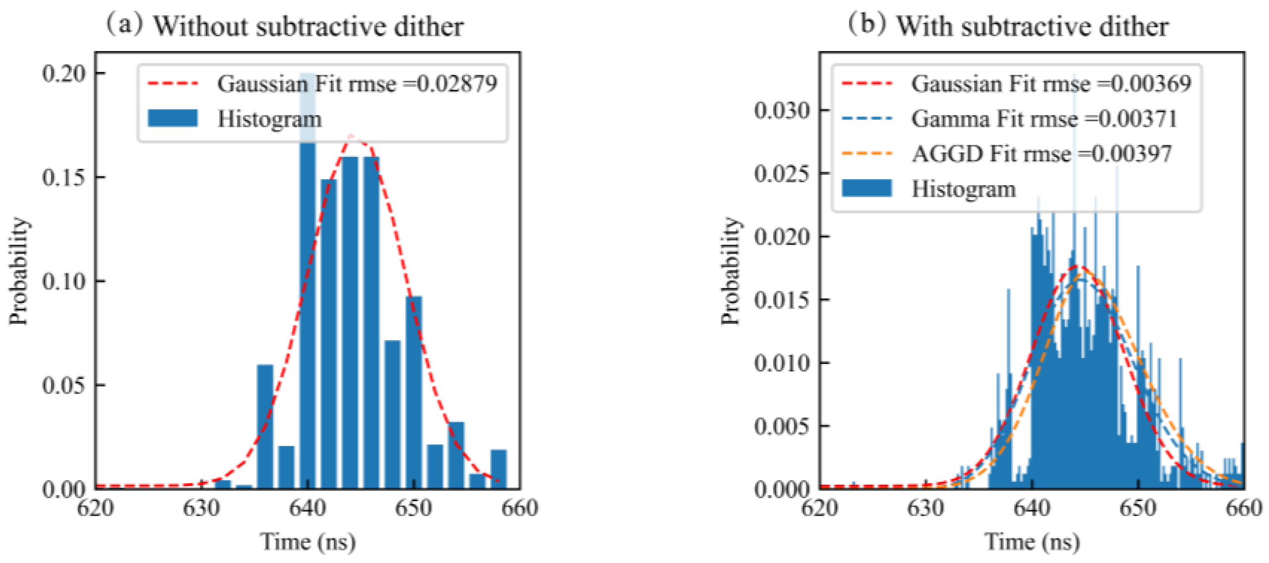
where V is the combination of noise terms. The generalized Gaussian distribution (GGD) and the exponentially-modified Gaussian distribution (EMGD) are used to model the sum of Gaussian and uniform noise terms [23,24]. Furthermore, Raghuram et al. have compared various methods based on the mean, median, and other symmetric linear combinations of order statistics to estimate mixed noise terms. As shown in Figure 2b, the photon counting histogram with dithering obtains a finer resolution. Here, the Gaussian distribution is a reasonable approximation to the dithered histogram rather than the Gamma distribution and asymmetric generalized Gaussian distribution (AGGD), which is a generalization of the GGD. The root mean squared error fitted with a Gaussian function decreases from 0.029 to 0.004 ns after a subtractive dither measurement. The photon counting histogram approximates the Gaussian distribution.
When the time delay step is τ , the up-sampling factor is defined as Δ / τ . A complete dithering measurement consists of a series of traditional measurements with discrete delay steps d i { 0 , τ , 2 τ , , Δ } . Although continuous delay steps are required in the established model, a large enough set of delay steps can eliminate the effect of discrete delays [24]. The mean is more suitable considering the computational cost and the dominance of Gaussian noise. As a result, the target distance μ ^ X ( i , j ) in the pixel ( i , j ) is estimated through the pixel-wise estimation from dithered measurements d k ( i , j ) , k = 1 , 2 , , K as
μ ^ X ( i , j ) = 1 K k = 1 K d k ( i , j ) .

2.1.2. Censoring of Photon Data

The subtractive-dithered depth estimation image is X i j n × n , where X i j is obtained from the subtractive dithered depth estimation μ ^ X ( i , j ) by Equation (3). In Section 2.1, the suspected targets are captured as much as possible. Outliers are eliminated since the smooth surface responses tend to cluster together. The median of the rank-ordered value X i j r of 8 neighboring pixels for each pixel ( i , j ) is applied for censoring the smooth surface responses [30]. The censored responses from the smooth surface are obtained by
G i j = { : | X i j ( ) X i j r | < ω , = 1 , 2 , , k i j } .
The smooth surface responses G i j are utilized for restoration directly, while others are replaced by the median of eight neighboring pixels for each pixel.

2.1.3. Depth Image Restoration

For the responses from the smooth surface, the 3D estimation for SPL is usually described as an inverse deconvolution problem. Then, the sparsity regularization method is employed because of the sparse prior for natural scenes [27]. Let Z , A n × n denote the scene’s depth and reflectivity matrix. A i j is the pulse response rate at the pixel ( i , j ) . Due to the Gm-APD’s counting process, the photon-flux for the pixel ( i , j ) results from an inhomogeneous Poisson process λ i j ( x ) = η A i j s ( x 2 Z i j / c ) + B i j , where η is the detection efficiency, c is the speed of light, and B i j n × n is the noise incident (e.g., ambient light, dark counts) at the Gm-APD detector. Here, a Gaussian approximation is applied to the IRF. The normalized laser pulse profile is s ( x ) = a exp ( ( x b ) 2 / 2 c 2 ) and s ( x ) d x = 1 , where the parameters are obtained from fitting the instrument response function. Assuming B i j = 0 ( i , j G i j ) after the censoring of photon data, the detected photon arrivals time X i j at pixel ( i , j ) has a probability mass function
f ( X i j | Z i j ) = X i j Δ X i j s ( x 2 Z i j / c ) d x X i j = 1 N X i j Δ X i j s ( x 2 Z i j / c ) d x , X i j = 1 , 2 , , N .
Through the left-Riemann sums to approximate the integrals, the negative log-likelihood function can be expressed as [27]
L Z ( Z i j | X i j ) = X i j 2 Z i j / c 2 2 .
The depth image is reconstructed by minimizing a regularized optimization problem with a total variance (TV) norm spatial smoothness constraint
Z ^ = arg min Z G i j L Z ( Z | X i j ( ) ) + β Z T V , s . t . Z i j > 0 .
This problem has been solved efficiently using SPIRAL-TAP [31]. Hence, the reconstructed depth image is achieved by the TV penalty. Finally, the results are compared with the ground truth images formed by the reconstructed depth image using thousands of photons. The MAE are used to quantitatively evaluate the performance of the reconstruction method, where the MAE are defined by
MAE = 1 n 2 i = 1 n i = 1 n | z i j z ^ i j | .

2.2. Dithered Single-Photon Lidar Measurement Setup

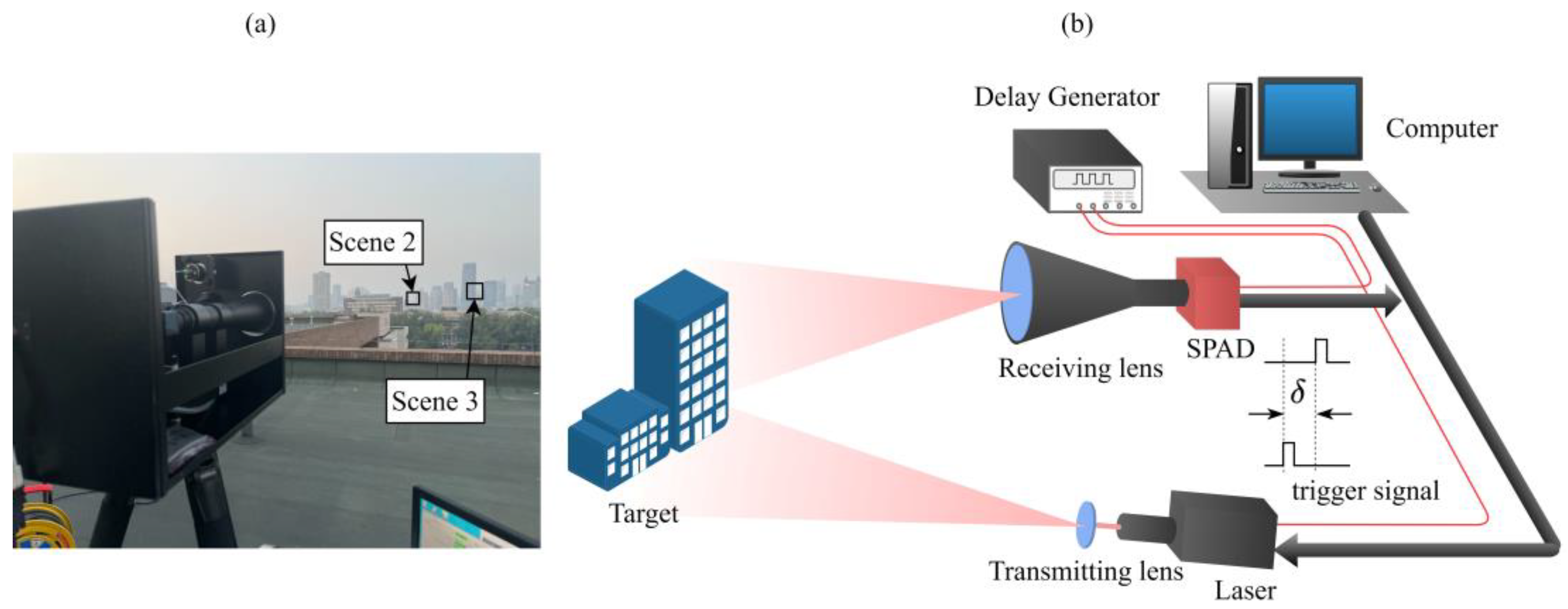
The experimental SPL system is shown in Figure 3. The scene of interest is illuminated by a pulsed laser and detected by a SPAD camera. The illumination source is a pulsed laser at 1064 nm with a pulse width of 10 ns and a repetition frequency of 20 kHz. The laser power is adjustable, and the maximum is 3.5 W. The detector is a 64 × 64 SPAD detector (CETC GD5551) with a time jitter of 350 ps, a dark count rate of 8 kHz, and a timing resolution of 2000 ps, which means the depth resolution is 0.3 m.
The transceiver system consists of a transmitting lens and a receiving optical system. The receiver field-of-view of the Lidar system is 0.75°, and the diameter of the receiver aperture is 76 mm. A 5 nm narrowband bandpass filter (Transmittance >80% at 1064 nm) and a low pass filter (Transmittance >91% at 550–1185 nm) are placed between the receiving lens and the detector to reduce the influence of the ambient light incident. The detector has a response wavelength range from 900 nm to 1700 nm. The low pass filter is used because the blocking wavelength range of the narrow bandpass filter is 1074 nm–1400 nm, which cannot block light from 1400 nm to 1700 nm.
The external trigger mode is applied because of the requirement of subtractive dither measurements. The single-photon camera operates in the traditional gating mode, synchronizing with the laser. At this time, the laser and the detector are only functional after being triggered by an external signal from the signal generator with a repetition rate of 20 kHz. Once the trigger signal is received, the laser source emits a light pulse with a pulse FWHM of 10 ns. Then, the laser beam is collimated through the transmitting optical system and illuminates the object.
To implement the range super-resolution measurement, a Digital Delay/Pulse Generator (DDG, Stanford Research Systems DG535) is utilized as the external trigger of both the laser source and the detector. High-precision digital delay control is obtained by adjusting the DDG (with an accuracy of up to 5 ps) to achieve the sub-bin accuracy—however, the normal Lidar proceeds without delay between the two channels. The times-of-flight of the different delays were measured individually to avoid the effect of the response delay from the trigger signal.

3. Results

The instrument response function is calibrated through a Gaussian approximation of the photon-counting histogram with a calibration target (a flat PolyVinyl Chloride board). Extraneous photon detections were suppressed by time-gating near the stand-off distance, measured by a laser rangefinder. The range super-resolution Lidar incorporates the delay between the laser and the detector with the delay step as 200 ps. Because the time resolution of SPAD is 2000 ps, the up-sampling factor is calculated as 10×. A complete dithering measurement consists of a series of traditional measurements with discrete delay steps d i { 0 , 200 , 400 , , 2000 } ps. The measurements are performed with and without subtractive dither under the same conditions. Before the estimation, we reject the noise photon based on photon TOF correlation for preprocessing. Specifically, the background responses are eliminated when the response times exceed the laser pulse width [32]. The parameter ω is used for censoring the noise signal and the parameter β weights the TV penalty in the optimization. In our strategy, the ω is twice as large as the time bin to simplify computations. The β is 0.3 through our parameter optimization tests. Finally, the performance of RSPE is compared with the traditional pixel-wise maximum-likelihood estimation and the regularized maximum-likelihood estimation, since they are the standard depth estimation algorithms in the development stage [27,33].
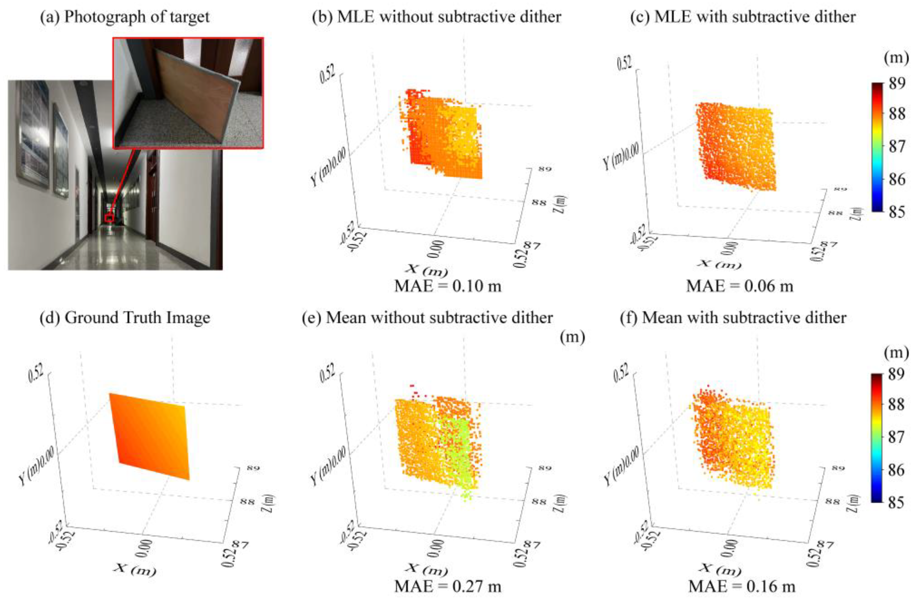
A validation experiment is performed with an inclined board as a target at a stand-off distance of about 88 m. The detected photons data are acquired with a laser power of 12 mW, and the SNR is 1.95. The imaging results, using hundreds of photons, are shown in Figure 4 (independent of the effect of regularization or other denoising approaches). Dithering improves the signal-to-noise ratio of the echo signal from 1.72 to 1.95 with the same data acquisition time. Then, the mean and MLE reconstruction algorithms are compared as follows. When the background noise weakens, MLE reduces to the log-matched filter [30]. It can be calculated through the correlation between the echo signal histogram and the calibration signal waveform, which is limited by the bin resolution of the original signal. As shown in Figure 4b, the quantized depth estimators are apparent. The dithered measurement achieves a sub-bin resolution because the dither signal is measured in a finer resolution. When the signal pulse width is larger than the bin resolution, the mean is also a method that can break through the bin resolution. Unfortunately, its performance is not excellent, as shown in Figure 4e,f.
It is difficult to obtain an actual depth image because of a lack of higher resolution imaging systems, especially in long-range imaging. The method of simulating the ground truth image with more signal photons is usually adopted to prevent a preference for the ground truth images. As shown in Figure 4d, the ground truth image is modeled by four vertices, and the MLE with subtractive dither has the greatest performance. Consequently, the ground truth images of long-range targets have been calculated using MLE with hundreds of signal photons.
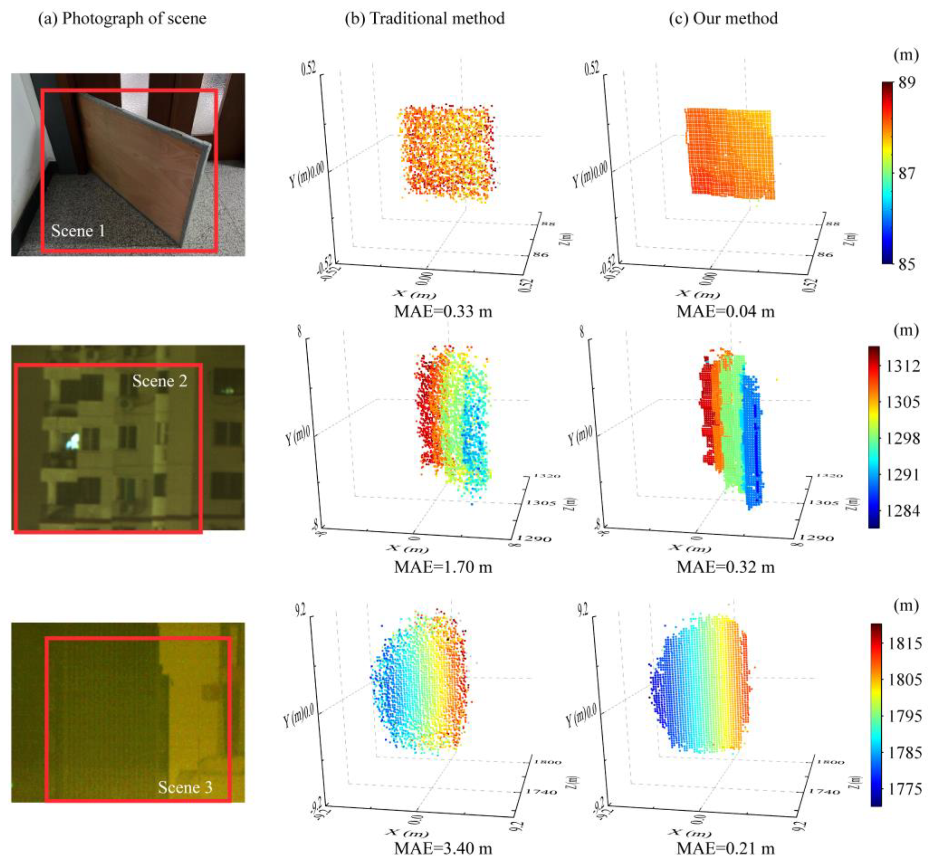
Targets with distinctive features and different distances form the three imaging scenes. As shown in Figure 5a, scene 1 is an inclined board at ~88 m, scene 2 has stepped surface features at ~1.3 km, and scene 3 varies in depth along with spatial dimensional at ~1.8 km. The detected photons data of scene 2 and scene 3 are acquired with a maximum power of 2.5 W. The sampling factor remains at 10 × in all the experiments. The reconstruction images using the traditional method are shown in Figure 5b, and the imaging results with RSPE are demonstrated in Figure 5c. The color bars on the right side show the distances from the target to the detector, calculated from the ToF. Compared with the traditional MLE method, the RSPE reduces the MAE by 8.3 × , 5.3 × , and 16.2 × with ~6 ppp. The improvement is more significant at long-range imaging and low SNR, and is related to the surface features of the target.
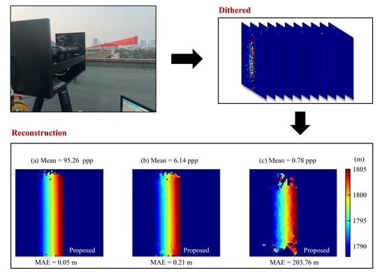
Furthermore, the normalized photon count images formed from the sum of all delay steps are shown in Figure 6, where the signal light level is lower than in the previous image [24]. The signal photon count increases as the target reflectivity is more substantial. The SNR is denoted as the number of detected signal pulses divided by the number of noise pulses. The extraneous noise photon detections were suppressed by strictly time-gating near the ground truth distance. Moreover, the longer distance of the target results in lower SNR because of the weaker signal. A weak intensity at the edge of the receiving field of view is due to the characteristics of the laser beam. For the three scenes, the SNRs are 1.95, 0.91, and 0.48. The imaging results under different conditions for scene 3 are also compared, as shown in Figure 7. Under the same signal light level, RSPE improves the MAE by one order of magnitude, which means a shorter acquisition time for long-distance imaging. In particular, the MAE is reduced from 1.60 m to 0.05 m using RSPE when the signal level is 95.26 ppp.
The performance of the depth reconstruction is evaluated using five different methods. Here, MLE refers to the traditional maximum likelihood estimation, which is a method for reconstructing depth information by pixel-wise processing photon counting histogram, similar to a matched filter [34]. The MAEs using different methods at a signal level of ~6 ppp are shown in Table 1. It is demonstrated below in Table 1 that RSPE outperforms the other methods. RSPE improves the efficiency of signal photons for subtractive dither imaging. The MAE for MLE and mean are equal when there are few signal photons. Moreover, the subtractive dither only reduced the MAE by 4.0 × , 5.2 × , and 16.1 × when comparing the Regularized MLE (the fourth column) and RSPE (the sixth column). The enhancement is more significant at low SNR.

4. Discussion

The ground truth image modeled by a mathematical method evaluates the ranging accuracy due to the lack of high timing resolution SPAD. Then, the recovery accuracy is analyzed with fewer signal photons. Compared with the higher recovery accuracy of ~mm, the decimeter accuracy is used because of the limitations of our experimental SPL system (e.g., system time jitter) [24]. A higher performance system will substantially improve the recovery accuracy. The depth image restoration algorithm mainly exploits the sparse prior information of natural images to improve the photon efficiency, which may bring excessive smoothing for a target with complex features. The application of other prior information further improves the depth recovery accuracy based on the RSPE. On the other hand, the system time jitter generally influences the depth recovery accuracy, which could be estimated from the IRF. However, the broader the IRF, the better the depth resolution, in some cases. The long pulse width laser beam adopted in this work has been approved to improve the depth recovery accuracy [29]. Dithered depth imaging with narrow pulses (less than the bin resolution) still needs to be investigated. Issues with the prior information and pulse width need to be discussed in the future to enhance the performance of dithered SPL at long-distance imaging.

5. Conclusions

We have described an SPL system operating at the wavelength of 1064 nm and demonstrated an imaging framework called RSPE to obtain high depth accuracy. The high depth resolution imaging at a distance up to 1.8 km is achieved by adopting a subtractive dither and penalized MLE. The RSPE is validated through indoor experiments. The MAE is reduced to approximately 0.06 m, which is below the system ranging resolution of 0.3 m. In outdoor experiments, RSPE improves the depth reconstruction error by at least 5.3 × compared with the traditional MLE. Increasing target distance brings depth uncertainty due to few reflected signal photons. Nonetheless, our method recovers depth features with higher precision through the same laser pulse response rate. The RSPE has overcome the rough depth resolution limited by the SPAD array with few signal photons, which paves the way to obtaining accurate depth reconstruction in long-range depth imaging.

Author Contributions

Conceptualization, J.C.; Formal analysis, J.C.; Funding acquisition, Y.W.; Investigation, J.C.; Methodology, J.C.; Project administration, D.X. and J.Y.; Software, J.C.; Supervision, J.L. and K.Z.; Validation, K.C. and S.L.; Writing—original draft, J.C.; Writing—review & editing, J.L. and D.X. All authors have read and agreed to the published version of the manuscript.

Funding

This research was funded by the National Natural Science Foundation of China, grant number U1837202, 62175182, and 62011540006.

Data Availability Statement

Data available on request due to restrictions eg privacy or ethical.

Conflicts of Interest

The authors declare no conflict of interest.

References

  1. Albota, M.; Gurjar, R.; Mangognia, A.; Dumanis, D.; Edwards, B. The Airborne Optical Systems Testbed (AOSTB). In Military Sensing Symp; MIT Lincoln Laboratory Lexington United States: Lexington, MA, USA, 2017. [Google Scholar]
  2. Clifton, W.E.; Steele, B.; Nelson, G.; Truscott, A.; Itzler, M.; Entwistle, M. Medium altitude airborne geiger-mode mapping lidar system. In Laser Radar Technology and Applications XX; and Atmospheric Propagation XII; SPIE: Bellingham, WA, USA, 2015; p. 9465. [Google Scholar]
  3. Rapp, J.; Tachella, J.; Altmann, Y.; McLaughlin, S.; Goyal, V.K. Advances in single-photon lidar for autonomous vehicles: Working principles, challenges, and recent advances. IEEE Signal Process. Mag. 2020, 37, 62–71. [Google Scholar] [CrossRef]
  4. Maccarone, A.; Acconcia, G.; Steinlehner, U.; Labanca, I.; Newborough, D.; Rech, I.; Buller, G. Custom-Technology Single-Photon Avalanche Diode Linear Detector Array for Underwater Depth Imaging. Sensors 2021, 21, 4850. [Google Scholar] [CrossRef] [PubMed]
  5. Li, Z.-P.; Ye, J.-T.; Huang, X.; Jiang, P.-Y.; Cao, Y.; Hong, Y.; Yu, C.; Zhang, J.; Zhang, Q.; Peng, C.-Z.; et al. Single-photon imaging over 200 km. Optica 2021, 8, 344. [Google Scholar] [CrossRef]
  6. Shen, G.; Zheng, T.; Li, Z.; Yang, L.; Wu, G. Self-gating single-photon time-of-flight depth imaging with multiple repetition rates. Opt. Lasers Eng. 2021, 151, 106908. [Google Scholar] [CrossRef]
  7. Shen, G.; Zheng, T.; Li, Z.; Wu, E.; Yang, L.; Tao, Y.; Wang, C.; Wu, G. High-speed airborne single-photon LiDAR with GHz-gated single-photon detector at 1550 nm. Opt. Laser Technol. 2021, 141, 107109. [Google Scholar] [CrossRef]
  8. Liu, D.; Sun, J.; Gao, S.; Ma, L.; Jiang, P.; Guo, S.; Zhou, X. Single-parameter estimation construction algorithm for Gm-APD ladar imaging through fog. Opt. Commun. 2020, 482, 126558. [Google Scholar] [CrossRef]
  9. Xu, W.; Zhen, S.; Xiong, H.; Zhao, B.; Liu, Z.; Zhang, Y.; Ke, Z.; Zhang, B. Design of 128 × 32 GM-APD array ROIC with multi-echo detection for single photon 3D LiDAR. Proc. SPIE 2021, 11763, 117634A. [Google Scholar]
  10. Padmanabhan, P.; Zhang, C.; Cazzaniga, M.; Efe, B.; Ximenes, A.R.; Lee, M.-J.; Charbon, E. 7.4 A 256 × 128 3D-Stacked (45 nm) SPAD FLASH LiDAR with 7-Level Coincidence Detection and Progressive Gating for 100 m Range and 10klux Background Light. Proc. IEEE Int. Solid-State Circuits Conf. 2021, 64, 111–113. [Google Scholar]
  11. Mizuno, T.; Ikeda, H.; Makino, K.; Tamura, Y.; Suzuki, Y.; Baba, T.; Adachi, S.; Hashi, T.; Mita, M.; Mimasu, Y.; et al. Geiger-mode three-dimensional image sensor for eye-safe flash LIDAR. IEICE Electron. Express 2020, 17, 20200152. [Google Scholar] [CrossRef]
  12. Jahromi, S.S.; Jansson, J.-P.; Keränen, P.; Avrutin, E.A.; Ryvkin, B.S.; Kostamovaara, J.T. Solid-state block-based pulsed laser illuminator for single-photon avalanche diode detection-based time-of-flight 3D range imaging. Opt. Eng. 2021, 60, 054105. [Google Scholar] [CrossRef]
  13. Henriksson, M.; Allard, L.; Jonsson, P. Panoramic single-photon counting 3D lidar. Proc. SPIE 2018, 10796, 1079606. [Google Scholar]
  14. Raghuram, A.; Pediredla, A.; Narasimhan, S.G.; Gkioulekas, I.; Veeraraghavan, A. STORM: Super-resolving Transients by OveRsampled Measurements. Proc. IEEE Int. Conf. Comput. Photog. 2019, 44–54. [Google Scholar] [CrossRef]
  15. Wu, J.; Qian, Z.; Zhao, Y.; Yu, X.; Zheng, L.; Sun, W. 64 × 64 GM-APD array-based readout integrated circuit for 3D imaging applications. Sci. China Inf. Sci. 2019, 62, 62407. [Google Scholar] [CrossRef]
  16. Tan, C.; Kong, W.; Huang, G.; Hou, J.; Jia, S.; Chen, T.; Shu, R. Design and Demonstration of a Novel Long-Range Photon-Counting 3D Imaging LiDAR with 32 × 32 Transceivers. Remote Sens. 2022, 14, 2851. [Google Scholar] [CrossRef]
  17. Yuan, P.; Sudharsanan, R.; Bai, X.; Boisvert, J.; McDonald, P.; Labios, E.; Morris, B.; Nicholson, J.P.; Stuart, G.M.; Danny, H.; et al. Geiger-mode ladar cameras. Proc. SPIE 2011, 8037, 803712. [Google Scholar]
  18. Pawlikowska, A.M.; Halimi, A.; Lamb, R.A.; Buller, G.S. Single-photon three-dimensional imaging at up to 10 kilometers range. Opt. Express 2017, 25, 11919–11931. [Google Scholar] [CrossRef]
  19. Li, Z.-P.; Huang, X.; Cao, Y.; Wang, B.; Li, Y.-H.; Jin, W.; Yu, C.; Zhang, J.; Zhang, Q.; Peng, C.-Z.; et al. Single-photon computational 3D imaging at 45 km. Photonics Res. 2020, 8, 1532. [Google Scholar] [CrossRef]
  20. Chen, Z.; Fan, R.; Li, X.; Dong, Z.; Zhou, Z.; Ye, G.; Chen, D. Accuracy improvement of imaging lidar based on time-correlated single-photon counting using three laser beams. Opt. Commun. 2018, 429, 175–179. [Google Scholar] [CrossRef]
  21. Rapp, J.; Dawson, R.M.A.; Goyal, V.K. Dither-Enhanced Lidar. In Applications of Lasers for Sensing and Free Space Communications; Optica Publishing Group: Hong Kong, China, 2018; p. JW4A-38. [Google Scholar]
  22. Rapp, J.; Dawson, R.M.A.; Goyal, V.K. Improving Lidar Depth Resolution with Dither. Proc. IEEE Int. Conf. Image Process. 2018, 1553–1557. [Google Scholar] [CrossRef]
  23. Rapp, J.; Dawson, R.M.A.; Goyal, V.K. Estimation From Quantized Gaussian Measurements: When and How to Use Dither. IEEE Trans. Signal Process. 2019, 67, 3424–3438. [Google Scholar] [CrossRef]
  24. Rapp, J.; Dawson, R.M.A.; Goyal, V.K. Dithered Depth Imaging. Opt. Express 2020, 28, 35143–35157. [Google Scholar] [CrossRef] [PubMed]
  25. Yan, K.; Lifei, L.; Xuejie, D.; Tongyi, Z.; Dongjian, L.; Wei, Z. Photon-limited depth and reflectivity imaging with sparsity regularization. Opt. Commun. 2017, 392, 25–30. [Google Scholar] [CrossRef]
  26. Altmann, Y.; Ren, X.; McCarthy, A.; Buller, G.S.; McLaughlin, S. Lidar Waveform-Based Analysis of Depth Images Constructed Using Sparse Single-Photon Data. IEEE Trans. Image Process. 2016, 25, 1935–1946. [Google Scholar] [CrossRef] [PubMed] [Green Version]
  27. Tachella, J.; Altmann, Y.; Marquez, M.; Arguello-Fuentes, H.; Tourneret, J.-Y.; McLaughlin, S. Bayesian 3D Reconstruction of Subsampled Multispectral Single-Photon Lidar Signals. IEEE Trans. Comput. Imaging 2019, 6, 208–220. [Google Scholar] [CrossRef]
  28. Kirmani, A.; Venkatraman, D.; Shin, D.; Colaço, A.; Wong, F.N.C.; Shapiro, J.H.; Goyal, V.K. First-Photon Imaging. Science 2014, 343, 58–61. [Google Scholar] [CrossRef]
  29. Shin, D.; Xu, F.; Venkatraman, D.; Lussana, R.; Villa, F.; Zappa, F.; Goyal, V.K.; Wong, F.N.C.; Shapiro, J.H. Photon-efficient imaging with a single-photon camera. Nat. Commun. 2016, 7, 12046. [Google Scholar] [CrossRef] [Green Version]
  30. Shin, D.; Shapiro, J.H.; Goyal, V.K. Single-Photon Depth Imaging Using a Union-of-Subspaces Model. IEEE Signal Process. Lett. 2015, 22, 2254–2258. [Google Scholar] [CrossRef] [Green Version]
  31. Harmany, Z.T.; Marcia, R.F.; Willett, R.M. This is SPIRAL-TAP: Sparse Poisson Intensity Reconstruction ALgorithms—Theory and Practice. IEEE Trans. Image Process. 2011, 21, 1084–1096. [Google Scholar] [CrossRef] [Green Version]
  32. Huang, P.; He, W.; Gu, G.; Chen, Q. Depth imaging denoising of photon-counting lidar. Appl. Opt. 2019, 58, 4390–4394. [Google Scholar] [CrossRef]
  33. Umasuthan, M.; Wallace, A.; Massa, J.; Buller, G.; Walker, A. Processing time-correlated single photon counting data to acquire range images. IEE Proc. Vis. Image Signal Process. 1998, 145, 237–243. [Google Scholar] [CrossRef] [Green Version]
  34. Kang, Y.; Li, L.; Li, D.; Liu, D.; Zhang, T.; Zhao, W. Performance analysis of different pixel-wise processing methods for depth imaging with single photon detection data. J. Mod. Opt. 2019, 66, 976–985. [Google Scholar] [CrossRef]
Figure 1. Flowchart of RSPE for depth reconstruction.
Remotesensing 14 05304 g001
Figure 2. The photon counting histogram at the pixel of (40,40) without denoising and correction. (a) without subtractive dither and (b) with subtractive dither.
Remotesensing 14 05304 g002
Figure 3. (a) A photograph of our experimental dithered single-photon lidar. (b) The system diagram.
Remotesensing 14 05304 g003
Figure 4. The 3D imaging result of SPL acquired by illuminating an inclined planar target at a distance of approximately 88 m. (a) The photograph of the target scene. (b) The reconstructed 3D image using MLE without subtractive dither. (c) The reconstructed 3D image using MLE with subtractive dither. (d) The ground truth image modeled by four vertices. (e) The reconstructed 3D image using the mean without subtractive dither. (f) The reconstructed 3D image using the mean with subtractive dither.
Remotesensing 14 05304 g004
Figure 5. The 3D imaging result for scene 1 (first row), scene 2 (second row), and scene 3 (third row) at different distances. (a) The photograph of the target scene. (b) The reconstructed 3D image with the traditional MLE method. (c) The reconstructed 3D image with RSPE.
Remotesensing 14 05304 g005
Figure 6. The number of detected signal photons per pixel (normalized) for the long-range imaging scenes in Figure 5.
Remotesensing 14 05304 g006
Figure 7. Comparison of depth imaging under different conditions for scene 3 at a distance of ~1.8 km. (a) The reconstructed 3D image with the signal photons of 95.26 ppp, (b) The reconstructed 3D image with the signal photons of 6.14 ppp, and (c) The reconstructed 3D image with the signal photons of 0.78 ppp.
Remotesensing 14 05304 g007
Table 1. MAE performance of the depth estimates with different methods.
MAE (m)
without Subtractive Ditherwith Subtractive Dither
SceneMLEMeanTV Regularized MLERSPE without TVRSPE
scene 10.330.350.160.210.04
scene 21.701.701.660.380.32
scene 33.403.403.390.260.21
Publisher’s Note: MDPI stays neutral with regard to jurisdictional claims in published maps and institutional affiliations.