Article

Mitigating Range Ambiguity Method Based on DDMA for SAR Systems

1
School of Marine Science and Technology, Northwestern Polytechnical University, Xi’an 710072, China
2
National Laboratory of Radar Signal Processing, Xidian University, Xi’an 710071, China
*
Author to whom correspondence should be addressed.
Remote Sens. 2022, 14(21), 5485; https://doi.org/10.3390/rs14215485
Submission received: 24 August 2022 / Revised: 30 September 2022 / Accepted: 28 October 2022 / Published: 31 October 2022
(This article belongs to the Section Remote Sensing Image Processing)

Abstract

:
Range ambiguity can lead to deterioration of imagery quality for space-borne synthetic aperture radar (SAR). To solve this problem, we propose a mitigating range ambiguity method based on Doppler division multiple access (DDMA) in this paper. With the orthogonality of the DDMA waveform, transmit channels are separated at the receiver. Afterwards, a pre-processed operation for definition domains of different transmit channels is put forward to transform all definition domains into the same one. Thereafter, by multiplying measured data in a transmit channel by the complex conjugation of those in the other channel, a coupling phase term between the ambiguous range and the Doppler can be generated. So, utilizing the coupling phase, the echoes of different ambiguous regions can be distinguished in the slow-time domain, and they are extracted by designing time domain passband filters. Moreover, the images of different extracted ambiguous regions can be reconstructed to compose the whole unambiguous image. Finally, simulation results exhibit the effectiveness of the proposed method.

Graphical Abstract

1. Introduction

Synthetic aperture radar (SAR) systems exhibit the capability of providing high-resolution images [1]. Therefore, they are widely employed in traffic control, battlefield surveillance, and so on [2,3]. Generally, high azimuth resolution is brought about by long synthetic aperture time. Meanwhile, to avoid azimuth ambiguity, a large pulse repetition frequency (PRF) is required. However, its results usually lead to range ambiguity [4]. Thus, the transmitted pulse at different slow times may be received simultaneously after reflected scatterers, such that the images of different range regions are folded and overlapped. In addition, the scatter points in the range ambiguity region cannot be defocused when the azimuth is compressed, so the imaging quality will deteriorate. Even worse, the range ambiguity problem is aggravated for the space-borne platform [5,6], as well as for high-resolution and wide-swath (HRWS) SAR [7,8].
To overcome the range ambiguity problem, many researchers have attracted growing attention. For single-channel SAR, a simpler technique in [9], namely low PRF, can avoid the range ambiguity effectively. However, the low PRF causes azimuth overlap when the PRF is less than the Doppler bandwidth. The authors in [10], by modulating each pulse, proposed a nonlinear suppression technique for range ambiguity resolution. Furthermore, in [11], the points of the range ambiguity region cannot be focused by transmitting alternately up and down chirp signals, such that the range ambiguity is suppressed. Afterwards, modulating coding based on the chirp signal in each pulse was deeply studied in [12], which combines amplitude and chirp signal modulation. However, these approaches cannot reduce the energy of the range ambiguity regions. In simple terms, it is difficult to obtain satisfactory results, since the single-channel SAR is limited by degrees of freedom (DOF). Therefore, the mitigating range ambiguity method based on the multi-channel SAR is widely concerned and improves the performance of the mitigating range ambiguity by utilizing the advantage of the DOF. For instance, the pulse phase coding (PPC) method was put forward by [13,14]. Herein, by only using the π and π phase in different transmitted pulses, the ambiguous range signals shift PRF/2 for the unambiguous range signal in the Doppler frequency domain. However, the method only separates either even order ambiguity or odd order ambiguity (rather than continuous order ambiguity). Therefore, this method has significant limitations. To compensate for its shortcoming, the authors from [15,16] proposed the azimuth phase coding (APC) method, which brings different shifting for different ambiguous region signals (the maximum shifting is PRF/2). Then, the range ambiguity is suppressed by a designed Doppler filter. Unfortunately, as there is an overlap between the unambiguous region and every ambiguous region, parts of range ambiguity regions have residual energies. Afterwards, by using the digital beamforming (DBF) in elevation, the range ambiguity resolution method was advanced [17,18], a method which transmits a wide beam and receives a narrow beam to suppress the energy of the range ambiguity regions. Meanwhile, a continuous PRI variation method was proposed to mitigate range ambiguity for staggered SAR systems [19]. However, it is difficult to distinguish the ambiguous echoes in elevation from the low grazing angle region, since the elevation angle varies very slowly with respect to the slant range. Fortunately, with the superiority of waveform diversity, multiple input multiple output (MIMO) systems can be combined with some other techniques to better resolve the range ambiguity problems, such as orthogonal frequency division multiplexing (OFDM) and frequency diverse array (FDA). However, the method based on the OFDM is faced with the increasing cost problem, as a result of the increasing bandwidth of the transmitted signal [20]. To deal with this problem, by utilizing a range-angle coupled transmit beampattern, the range ambiguity can be separated in the transmitted spatial domain with FDA-MIMO radar systems [21,22]. In [23], a novel approach with DBF and vertical FDA was proposed. Using this approach, one can obtain an HRWS-SAR image and improve the signal-to-noise ratio (SNR). However, a reliable separation of the radar echoes arising from the simultaneous use of multiple transmitted signals is needed. It is a fundamental challenge related to the low-frequency difference for MIMO-SAR systems [24].
Through the above analysis, it is evident that the mitigating range ambiguity needs to utilize the DOF effectively. Fortunately, Doppler division multiple access (DDMA) waveform [25] can be modulated to different parts in the Doppler space [26] by the echo transmitted element assigning a slow time coding. Thus, the echoes from different transmitted elements can be separated by Doppler filters in the receiver, so that more DOF is provided to the system. Furthermore, utilizing the advantage of the DOF brought about by the DDMA, the DDMA approach was first used in airborne platforms for ground moving target indication (GMTI) [26,27,28]. Thereafter, a DDMA-based blind velocities mitigation method was provided in [29], and a Doppler ambiguity resolution method based on the DDMA was presented in [30]. In addition, a transmitted beamspace based on DDMA was investigated to improve the transmit energy distribution for an automotive MIMO radar [31]. To sum up, inspired by the influence of the DOF on the performance of the range ambiguity suppression, aiming at the range-ambiguity-to-signal ratio can be improved effectively by the DDMA waveform.
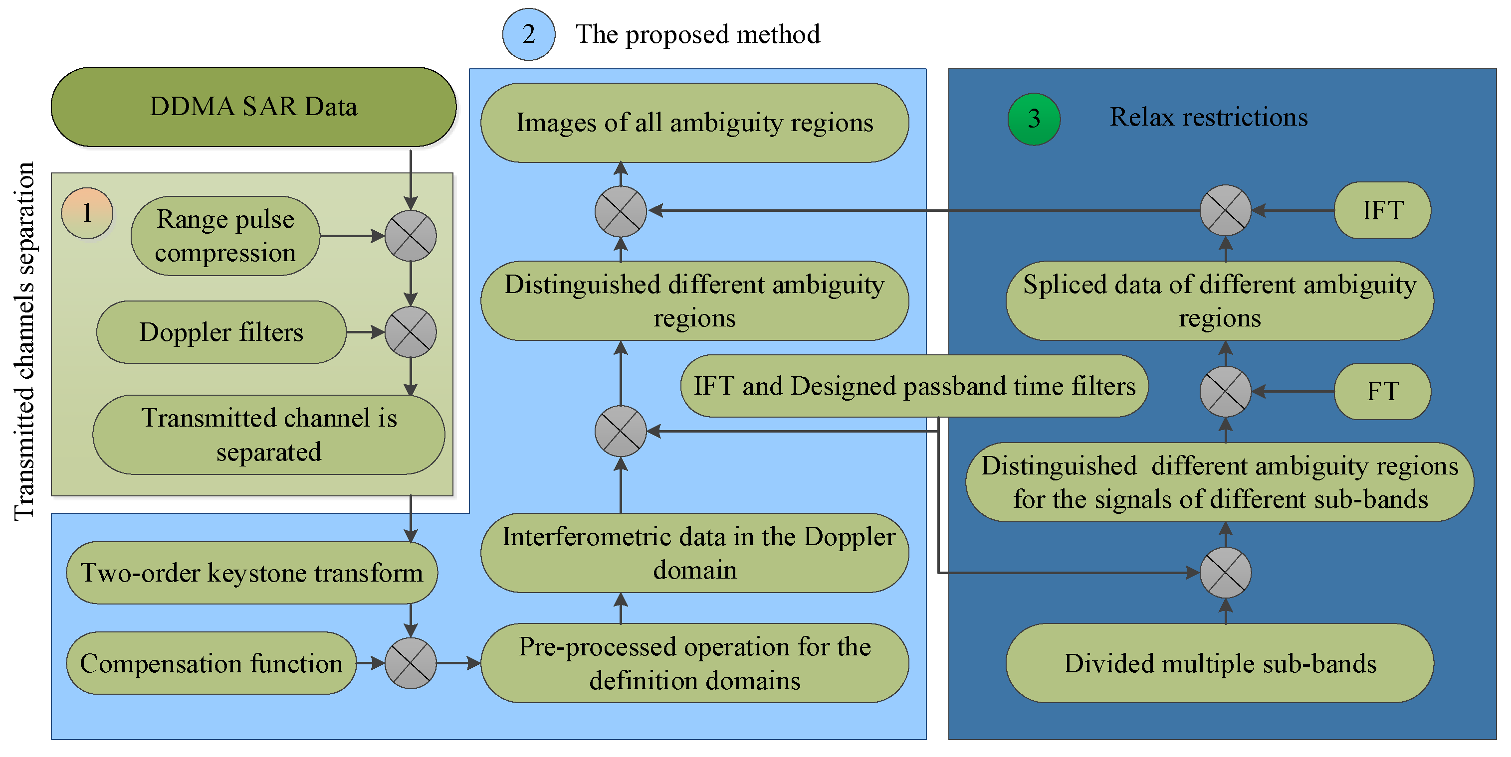
In this paper, a mitigating range ambiguity method is proposed by using the DDMA waveform to deal with the range ambiguity problem in a small signal bandwidth and continuous order regions. The proposed method is divided into four steps. Firstly, the echoes of different transmitted channels need to be separated by the Doppler filters to increase the DOF of systems. Unfortunately, the definition domains of the echo data with different transmitted channels are different. Therefore, through a provided pre-processed operation, the echo data are transformed into the same definition domain after application of a compensation function and two-order keystone transform. Secondly, the interferometric data between channels are obtained, whereby measured data in a channel are multiplied by the complex conjugation of those in the other channel. This indicates that there is a coupling phase term exp j π f a f D D M A λ R k , l / V 2 in the phase of the interferometric data, which contains the ambiguous range and the offset Doppler f D D M A . Herein, the phase of the interferometric data is a linear function with regard to the Doppler frequency, where the first-order coefficient contains ambiguous range information. Thirdly, with the coupling phase term, by transforming the interferometric data of the Doppler domain into the slow-time domain, the echoes of different ambiguous regions can be distinguished, even for continuous order range ambiguity. Thereafter, the echo data of different ambiguous regions can be extracted by designing passband filters in the slow-time domain. Lastly, the images of different ambiguous regions are reconstructed to construct the whole image. At the same time, simulation results verify the effectiveness of the proposed method.
The remainder of this paper is organized as follows: in Section 2, we introduce the SAR imaging geometry and the signal model, while the mitigating range ambiguity based on the DDMA waveform method is proposed in Section 3. Simulation results are presented in Section 4. In Section 5, we provide concluding remarks.
Notations: We denote vectors and matrices by boldface lowercase and uppercase letters, respectively. · * denotes the conjugate operator.

2. Signal Model

A multi-channel SAR system works in the strip-map mode with the geometry shown in Figure 1.
Assume that there are N channels, the first channel is the received channel, and all channels are transmitted channels. The velocity and height of the radar platform are denoted by V and H , respectively. The instant range is R k , l = H 2 + y k 2 when the radar boresight is directed to the k th point in the l th ambiguous region. Denote R n k , l t as the distance between the n th channel and the k th scatterer P x k , y k in the l th ambiguous region at a slow time t . We take the location of the aircraft at t = 0 on the ground, O , as the origin of the coordinate system. The x-axis points in the same direction as the velocity vector of the platform, and the coordinates of the receiver are 0 , 0 , H . The x o y plane is on the ground plane, and the z-axis points vertically upwards. The fast-time in the range dimension and the slow-time in the azimuth dimension are represented as u and t , respectively. Therefore, R n k , l t expanded by Taylor expansion can be expressed as:
R n k , l ( t ) R k , l + V t x k + d ( n 1 ) 2 2 R k , l
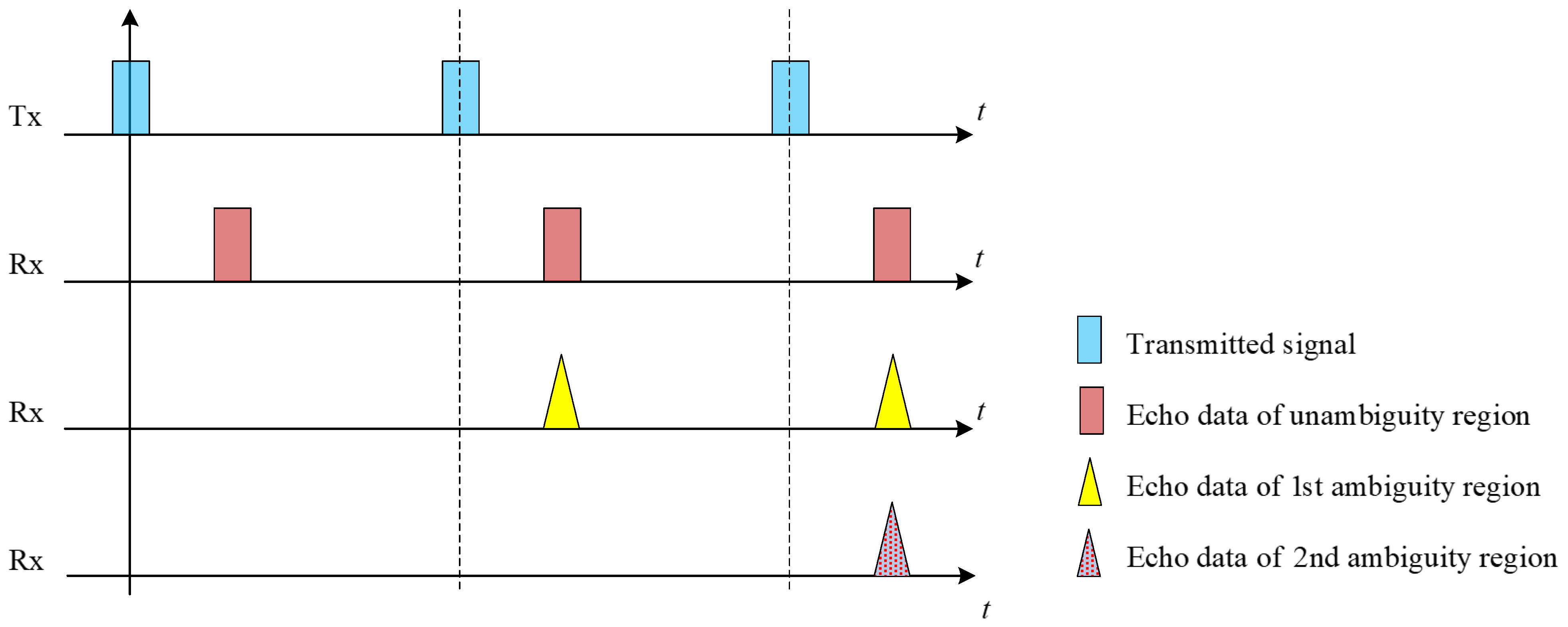
where R k , l = R k + l 1 Δ R is the instant range when the radar boresight is directed to the k th point in the l th ambiguous region, the maximum unambiguous distance is Δ R = c / 2 P R F , and P R F and c represent the PRF and light speed, respectively. Denote d as the inter-element spacing. Herein, if the range between two scatter points is Δ R , the echo signals in the unambiguous region and the ambiguous region arrive simultaneously (see Figure 2). Then, it is difficult to distinguish the echo data of the unambiguous region and the ambiguous region, that is, the range ambiguity problem has occurred.
Since different channels transmit DDMA waveforms with slow-time modulation, the orthogonality among channels is achieved in the Doppler domain. Notably, in order to separate the transmit channel in the receiver, the Doppler shift f D D M A among the channels need to satisfy the condition
B D o p p l e r < f D D M A < P R F / N
where B D o p p l e r is the Doppler bandwidth. Then, suppose that the LFM signal in the n t h channel is transmitted with the following form:
s n ( u , t ) = r e c t u exp j ( 2 π f 0 u + π K u 2 + φ n ( t ) )
where r e c t · , f 0 , and K are rectangular window function, carrier frequency, and chirp rate, respectively. Meanwhile, the phase of slow-time modulation in the n th transmit channel is φ n ( t ) = 2 π n 1 f D D M A t . This leads to a Doppler shift f D D M A among the channels. Hence, the received baseband signal from the echoes of all scatterers in the interesting scene is derived:
s ( u , t ) = n l k σ k r e c t u R n k , l t + R 1 k , l t c w a t x k / V × exp j 2 π f 0 u R n k , l t + R 1 k , l t c + j π K u R n k , l t + R 1 k , l t c 2 × exp j 2 π n 1 f D D M A t
where σ k stands for the complex reflectivity for the k th scatter point, and w a t represents the azimuth envelope before azimuth compression. After down-conversion and range pulse compression, (4) can be rewritten as:
s ( u , t ) = n l k σ k p r u R n k , l t + R 1 k , l t c w a t × exp j 2 π R n k , l t + R 1 k , l t λ + j 2 π n 1 f D D M A t
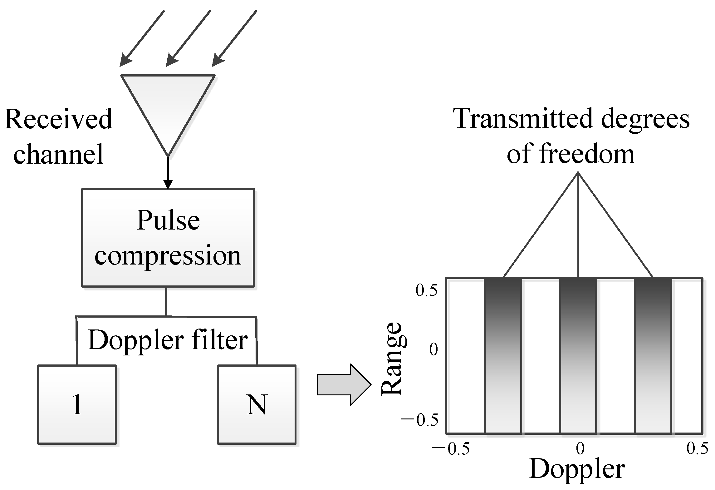
where λ denotes radar wavelength and p r u is the range envelope after range pulse compression. Here, as the offset Doppler f D D M A satisfies (2) among the channels, the transmit channel is separated in the receiver after the echo signal is processed by the Fourier transform (FT) and the bandpass filter, and this block diagram is presented in Figure 3.
The separated echo data of the n th transmitted channel is gotten by:
s n ( u , t ) = l k σ k p r u R n k , l t + R 1 k , l t c w a t × exp j 2 π R n k , l t + R 1 k , l t λ + j 2 π n 1 f D D M A t l k σ k p r u R n k , l t + R 1 k , l t c w a t × exp j 2 π λ 2 R k , l + V t x k + n 1 d 2 2 R k , l + V t x k 2 2 R k , l × exp j 2 π n 1 f D D M A t
Meanwhile, the DOF of the systems increases by DDMA waveforms in the receiver.

3. A Mitigating Range Ambiguity Based on DDMA Waveform Method

In this section, we expand on how to utilize the increased DOF to suppress range ambiguity. For easy of analysis, let x k = 0 :
s n ( u , t ) = l k σ k p r u R n k , l t + R 1 k , l t c w a t × exp j 2 π λ 2 R k , l λ n 1 f D D M A t + V t + n 1 d 2 2 R k , l + V t 2 2 R k , l
By FT in the fast-time domain, (7) can be written as:
s n ( f r , t ) = l k σ k p r f r w a t exp j 2 π λ f r + f 0 n 1 f D D M A t c × exp j 2 π f r + f 0 c 2 R k , l + V t + n 1 d 2 2 R k , l + V t 2 2 R k , l
As seen from (8), the range frequency f r and the slow time t exhibit coupling terms. It leads to range migration, causing the image quality to decrease. Herein, we eliminate the range migration by two-order keystone transform, that is, one can make the transform as:
f r + f 0 t 2 = f 0 τ 2
where τ is the new slow-time. Combining (8) and (9), it is easy to get the following formula into the two-dimensional time domain as:
s n ( u , τ ) l k σ k p r u w a τ exp j 2 π n 1 f D D M A τ × exp j 2 π λ 2 R k , l + V τ + n 1 d 2 2 R k , l + V τ 2 2 R k , l
Then, substitute the stationary phase into FT integral, and the echo signal in the range-Doppler domain can be obtained:
s n ( u , f a ) = l k σ k p r u w a f a × exp j π f a n 1 f D D M A + n 1 d V λ R k , l 2 2 V 2 λ R k , l exp j π n 1 d 2 λ R k , l = l k σ k p r u w a f a × exp j π f a 2 + n 1 f D D M A 2 2 V 2 λ R k , l exp j π f a n 1 f D D M A λ R k , l V 2 × exp j π n 1 d f a n 1 f D D M A V exp j π n 1 d 2 2 λ R k , l
where the definition domain of the Doppler frequency f a for the echo of the n th transmit channel is:
f a , n B 2 + n 1 f D D M A , B 2 + n 1 f D D M A
Meanwhile, we can construct a compensation function H 2 u , f a to remove the invalid term for the mitigating range ambiguity in (11):
H 2 u , f a = exp j π n 1 d f a n 1 f D D M A V
After the phase compensation in the range-Doppler domain, (11) is written as:
s n ( u , f a ) = l k σ k p r u w a f a exp j π f a 2 + n 1 f D D M A 2 2 V 2 λ R k , l × exp j π f a n 1 f D D M A λ R k , l V 2 exp j π n 1 d 2 2 λ R k , l
Note that the definition domains of the Doppler frequency in different channel data are different. Therefore, the data of the two channels cannot be processed directly by using interference. So, the data of all channels need to be pre-processed. Please see Appendix A for the pre-processed operation.
After the data of all channels are transformed into the same definition domain, the data of the 1 st and 2 nd channels processed by an interferometric method is expressed as:
y u , f a = s 2 ( u , f a ) s 1 * ( u , f a ) = l k σ k p r u w a f a × exp j π f D D M A 2 λ R k , l 2 V 2 exp j π f a f D D M A λ R k , l V 2 exp j π d 2 2 λ R k , l
From (15), the first-order coefficient of the Doppler frequency f a contains the range information R k , l in the phase, and there are no high-order terms of the Doppler frequency f a . Then, if the coupling term exp j π f a f D D M A λ R k , l / V 2 in (15) is transformed into the slow-time domain by the inverse Fourier transform (IFT), the first-order coefficient of the Doppler frequency f a is transformed into the azimuth envelope function as:
y u , t = l k σ k p r u w a t f D D M A λ R k , l 2 V 2 × exp j π f D D M A 2 λ R k , l 2 V 2 exp j π d 2 2 λ R k , l = l k σ k p r u w a t f D D M A λ R 0 + l 1 Δ R 2 V 2 × exp j π f D D M A 2 λ R k , l 2 V 2 exp j π d 2 2 λ R k , l
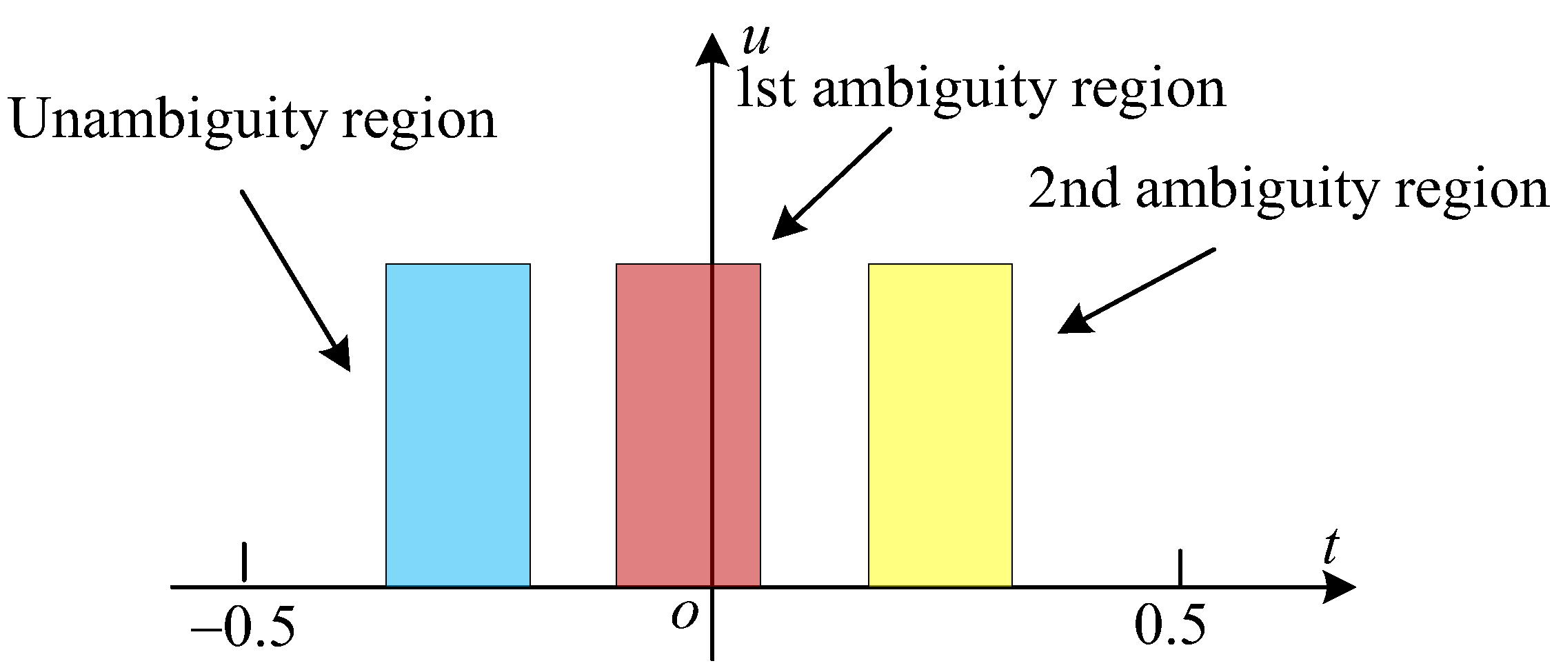
Thus, it can be observed that the data of different ambiguous regions are distinguished in the slow-time domain by (16), and the distinguished spacing between different ambiguous regions is f D D M A λ Δ R / 2 V 2 . Meanwhile, the diagram of the separated data is described in Figure 4.
Subsequently, the data in Figure 4 can easily mitigate range ambiguities by time domain filters. Significantly, the essence of the proposed method is that the coupling term of the range R k , l and the Doppler frequency f a produces a shifting time in the slow-time domain. Therefore, if the illumination time is longer than the shifting time of the different ambiguous regions caused by the proposed method, the aliasing is brought among different ambiguous regions in Figure 5. So, the applicable conditions of the proposed method are explored further in this paper.
From Figure 5, it is observed that the limiting factor of the proposed method is the illumination time rather than the number of channels. This leads to a decrease in the azimuth resolution and affects the long continuous scene imaging in azimuth. Thus, to avoid aliasing regions, the following inequality should be satisfied:
T i l l u λ R 0 D a V < f D D M A λ Δ R 2 V 2
where T i l l u and D a are the illumination time of points in the area of interest (AOI) and the azimuth aperture of radar, respectively. Under the azimuth resolution of the SAR system, (17) can be reformulated as:
Δ R > 2 R 0 V D a f D D M A = R 0 V ρ a f D D M A   or   f D D M A > R 0 V Δ R ρ a
where ρ a denotes the azimuth resolution. Therefore, these restrictions are not satisfactory. Fortunately, from (15), it can be seen that there is the ambiguous range R k , l in the function phase, namely exp j π f a f D D M A λ R k , l / V 2 . Meanwhile, the causes of the overlap in the two-dimensional time domain are that the echoes of ambiguous regions are shifted into the unambiguous region on the echo of other slow time. Therefore, to eliminate the limitation in azimuth, we divide the Doppler domain into multiple sub-bands in a synthetic aperture time (the number of sub-bands is M b = 2 R 0 V f D D M A Δ R D a ). Then, the data of different ambiguous regions are distinguished by the proposed method in the slow-time domain for the signals of different sub-bands. Thereafter, all sub-band data of every ambiguous region are spliced in the Doppler domain. Finally, focused images in different ambiguous regions are acquired in the slow-time domain. Thus, as these processes have one more FT and IFT operations than the direct solution, the computational complexity increases by approximately O M a 2 ( log 2 M a / M b + log 2 M a ) ( M a is the number of slow time sampling points). In this way, the advantage of this process is that, although the computational complexity is increased, the constraint is relaxed. Namely, the proposed method makes a tradeoff between the computational burden and the azimuth resolution, and a block diagram of the proposed method is illustrated in Figure 6.

4. Numerical Simulations

In this section, we show simulations and analysis to illustrate the proposed method, of which the effectiveness is verified by the points in the AOI simulation below. In Table 1, the parameters for the spaceborne SAR operation used in this paper are listed.
Assume that the clutter-to-noise ratio (CNR) is C N R = 40   dB . Note that the spacing of the Doppler f D D M A between the channels has been discussed in the above section. Here, f D D M A = 1500 Hz . For ease of verification, we separate the full swath into three range regions in the same azimuth area by the maximum unambiguous distance and denoted them by their order. In addition, the performance of the proposed method is discussed in four aspects.

4.1. Differences of the Mitigating Range Ambiguity Method

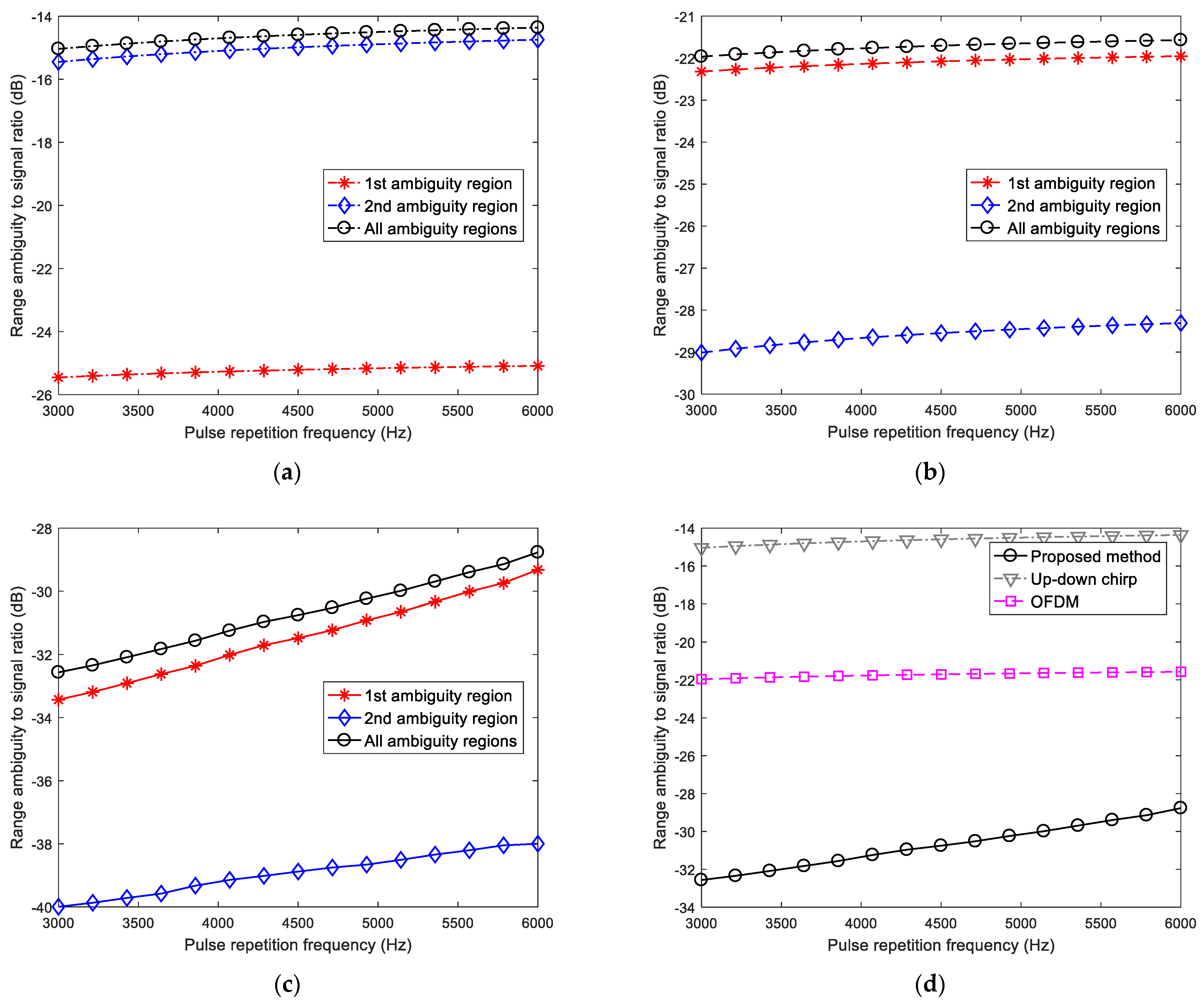
To compare the range ambiguity suppression performance with conventional SARs, we consider a near-space high-PRF SAR. The system parameters are included in Table 1. Here, we analyze only the range ambiguity under the same conditions except for PRF, when there is no azimuth ambiguity. Therefore, the range ambiguity is evaluated by the range-ambiguity-to-signal ratio (RASR) versus PRF [32], which is determined by summing all signal components R A S R l . Furthermore, R A S R l is the ratio of this sum to the integrated signal return from the desired pulse within the data record window arising from the preceding and succeeding pulses. It is worth highlighting that the smaller the RASR, the higher the imaging quality becomes. The calculation equation for the RASR is:
R A S R = l R A S R l = l R max R max ξ l G l 2 σ l R l 3 sin α l d r R max R max G 0 2 σ 0 R 0 3 sin α 0 d r
where ξ l is the beamforming gain at the range of R l , G l is the cross-track antenna pattern in the l th time interval of the data recording window at a given α l , and σ l is the corresponding normalized backscatter coefficient. R 0 , G 0 , α 0 , and σ 0 are the corresponding parameters of the desired unambiguous return.
Figure 7 shows the comparative RASR performance, which is a function of the PRF. Note that the selected minimal PRF is greater than the Doppler band, so there is no azimuth ambiguity. From Figure 7b,c, the primary overlap of ambiguous returns comes from the 1 st ambiguous region after range-ambiguity suppression. However, the principal component of the RASR is the signal of the 2 nd range ambiguity for the up-down chirp method, as in Figure 7a. The main reason for this is that the echo is not focused on the range-time domain for the up-down chirp method. Figure 7d presents an illustration of the RASR versus PRF on the OFDM, the up-down chirp, and the proposed methods. As the signal of the 2 nd range ambiguity cannot be suppressed in the range-time domain for the up-down chirp method, it is observed that the calculated RASR (about −15 dB) is the highest. Compared with the up-down method, the RASR of the OFDM method has a better performance (about 7 dB less), because orthogonal coding is used to distinguish the echoes in different ambiguous regions on the OFDM method. However, the echoes from the different ambiguous regions have the same position in the fast-time domain, so the RASR performance is not satisfactory. For the proposed method, not only the orthogonality among the range ambiguity regions is utilized, but also different ambiguous regions are shifted to different azimuth positions. Therefore, it can achieve a superior RASR performance (approximately −29 to −32 dB). These results clearly show that a significant RASR performance improvement can be gotten by our approach. This means that a wider swath can be obtained, without decreasing the operating PRF. Moreover, the high PRF allows for a robust Doppler frequency tolerance and a higher Doppler resolution.

4.2. Only One Center Point in Each Region

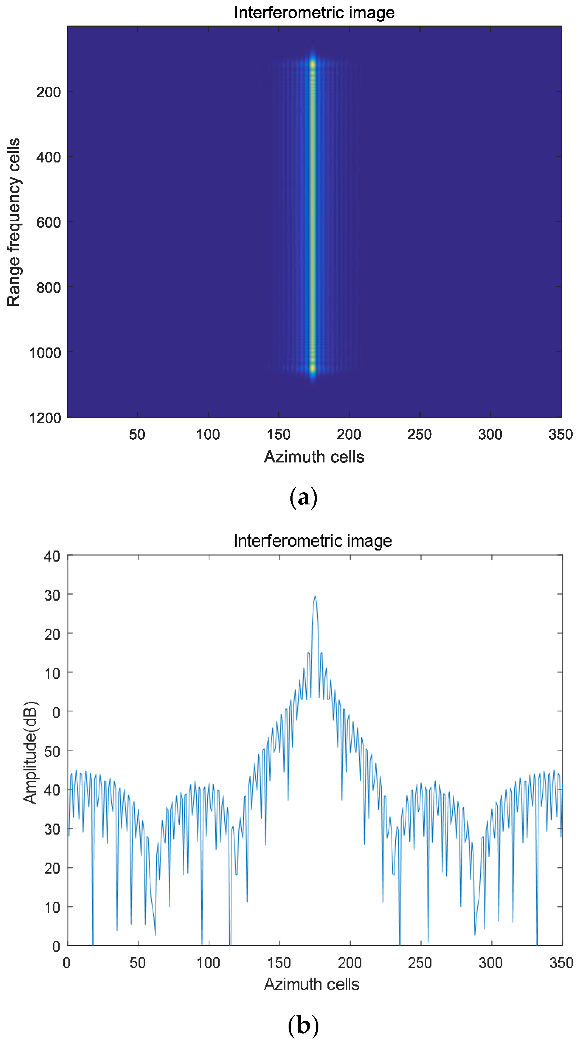
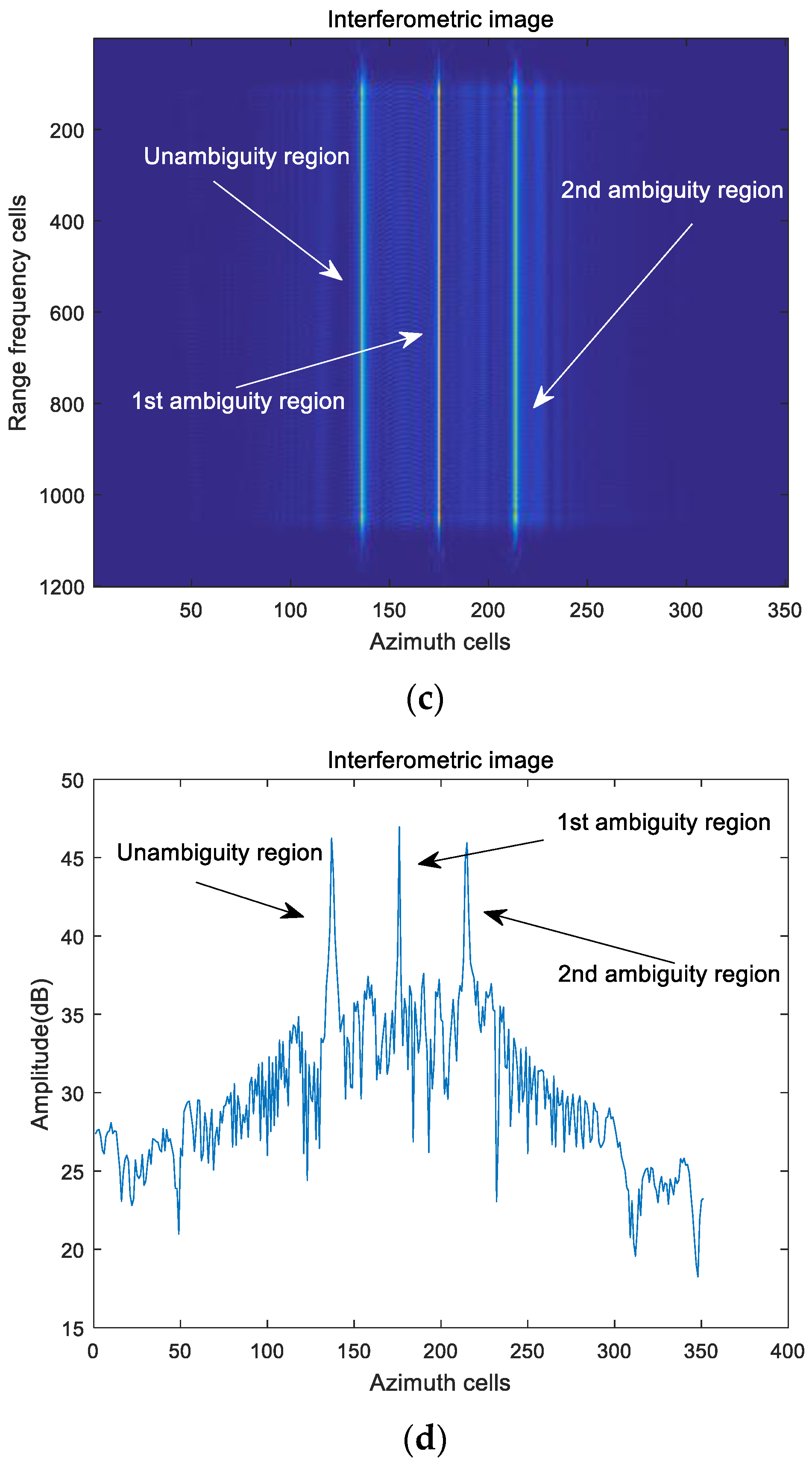
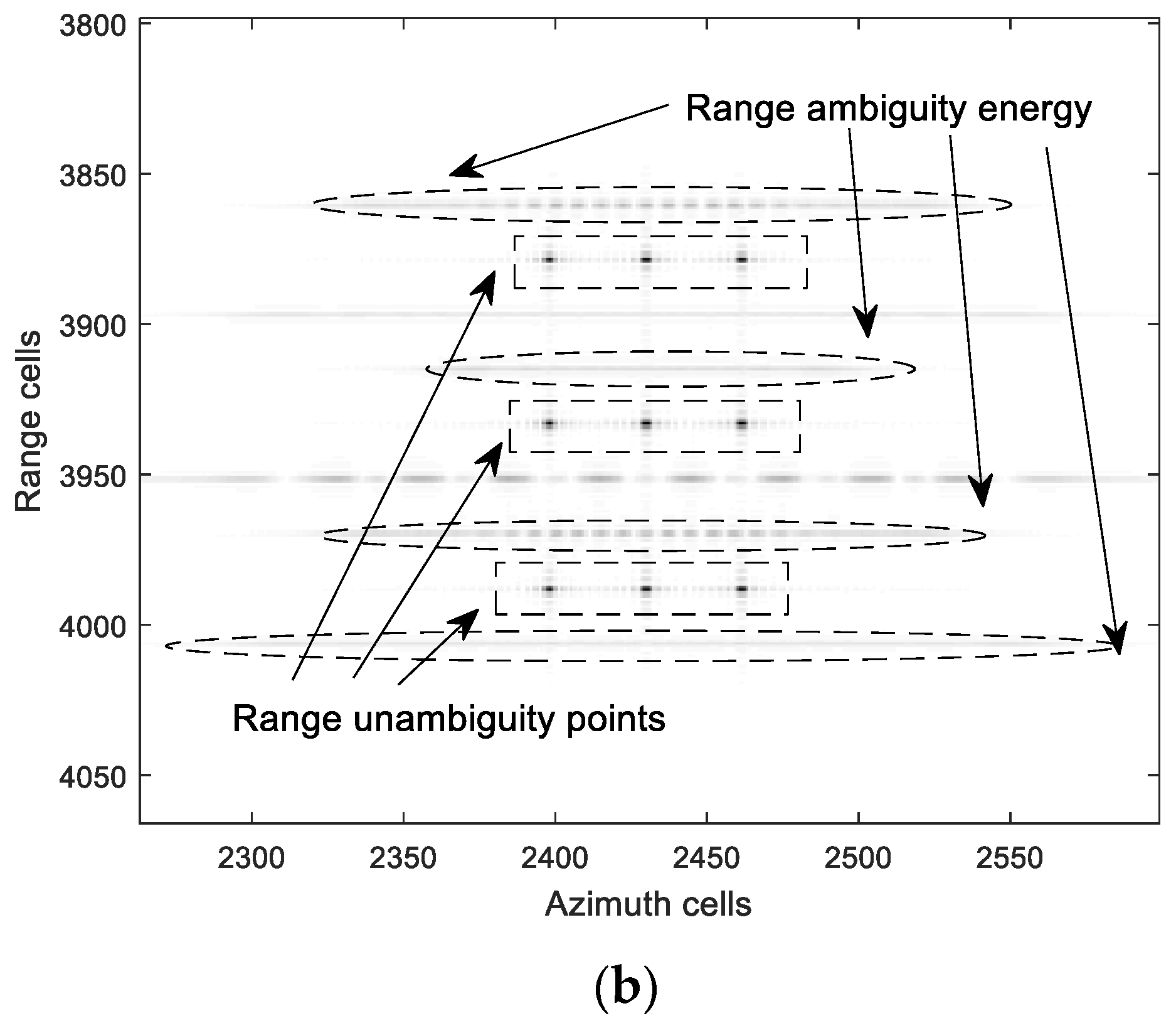
Assume that there is only one center point in each region, these center points have the same azimuth position in their respective regions, and the range between two continuous regions is the maximum unambiguous distance. Therefore, the measured echo delays of these center points are the same, such that the echo data of the points overlap in the range-time domain. Figure 8a depicts the interferometric image after range pulse compression by using traditional MISO-SAR (without using DDMA waveforms). Figure 8b is the elevation slice diagram of Figure 8a. As observed, the echo data of all points overlap in the same place. Thus, the different ambiguous regions are indistinguishable. For DDMA-SAR, there is a coupling term between the Doppler frequency f a and the range R k , l in the two-dimensional frequency domain. Hence, after transforming the interferometric image between the two channels into the azimuth-time domain, the points in different ambiguous regions can be distinguished. Moreover, the interferometric image between the two channels is described in Figure 8c. It can be seen that not only the center points in different ambiguous regions are separated in the azimuth-time domain, but also the offset of azimuth time increases with the increase in range. This property can help us to design a passband time filter to extract data from different regions.

4.3. Design of the Passband Time Filter

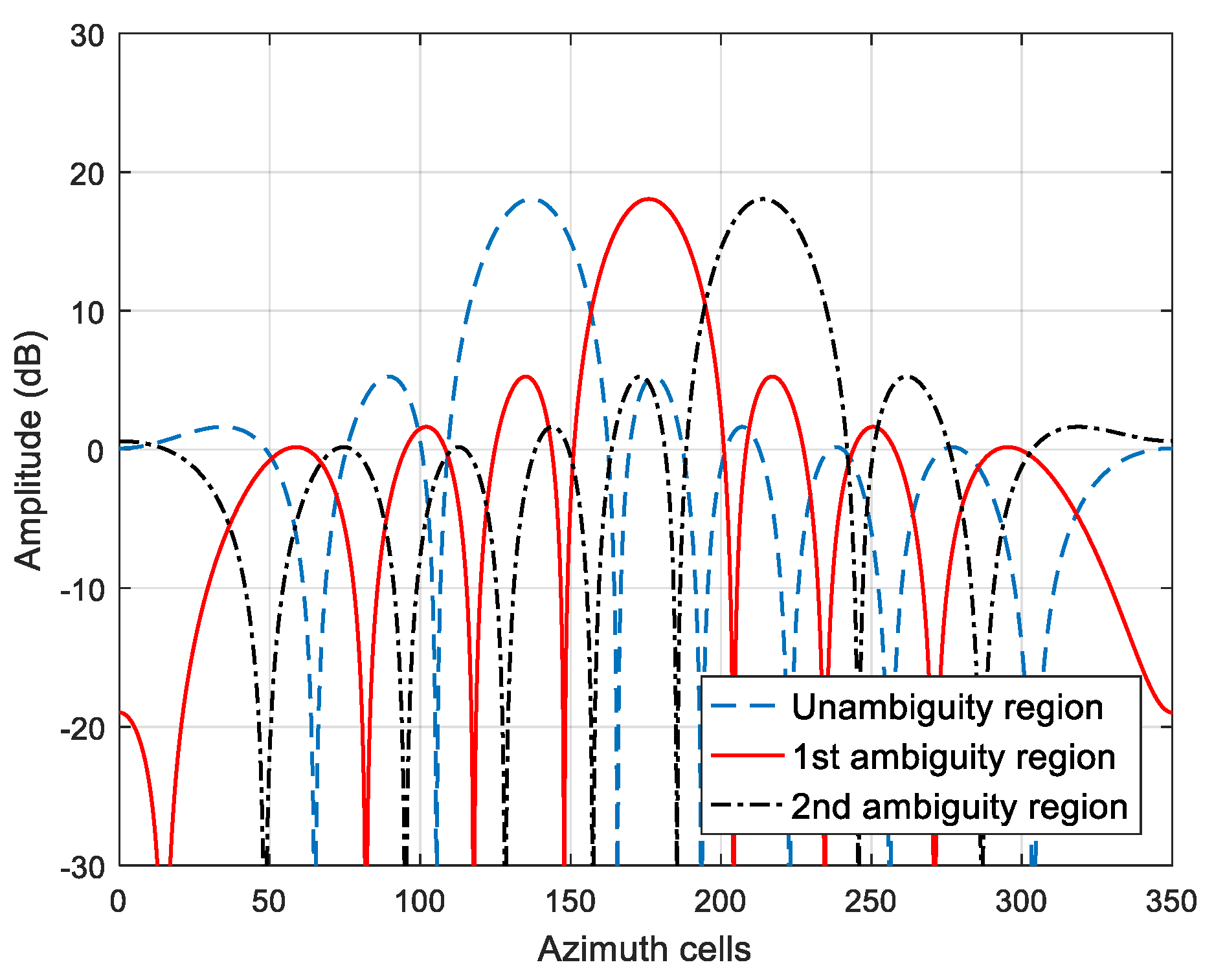
In the subsection, a passband time filter for the extracted ambiguous region is designed. To enhance the signal gain of the desired range region, while suppressing the range ambiguities from other range regions, the peak positions of center points and the distances among the center points are required. In other words, the position of the main lobe peak depends on the peak position of the center points, and the 3 dB width of the main lobe is decided by the distance between the center points. According to the above criterion, the designed passband time filters are given in Figure 9. It can be observed that a set of filters exhibits orthogonality. Namely, the main lobe of one filter coincides with the side lobes of the other filters and does not coincide with the main lobes. Therefore, low correlation decreases interference among different regions. Moreover, by controlling the peak sidelobe ratio and the integral sidelobe ratio, a superior performance can be achieved by the designed passband time filters.

4.4. Multiple Points in Each Region

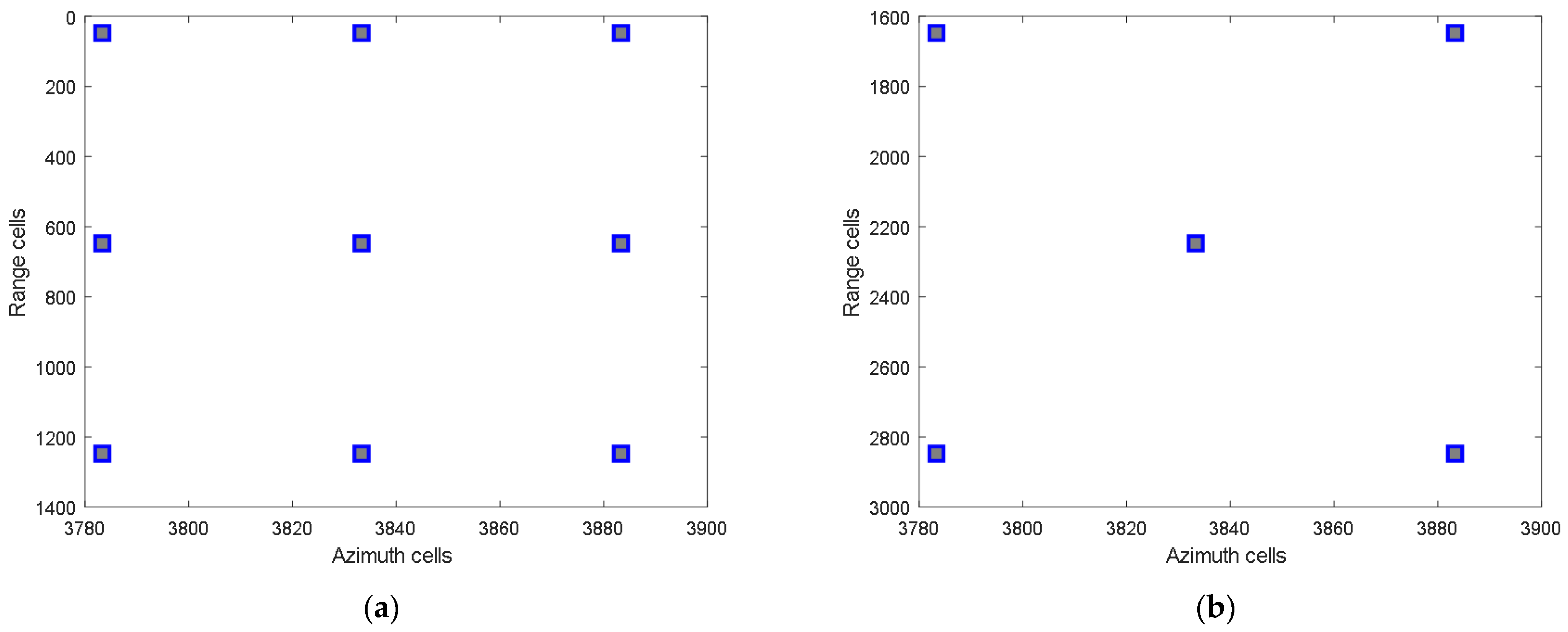
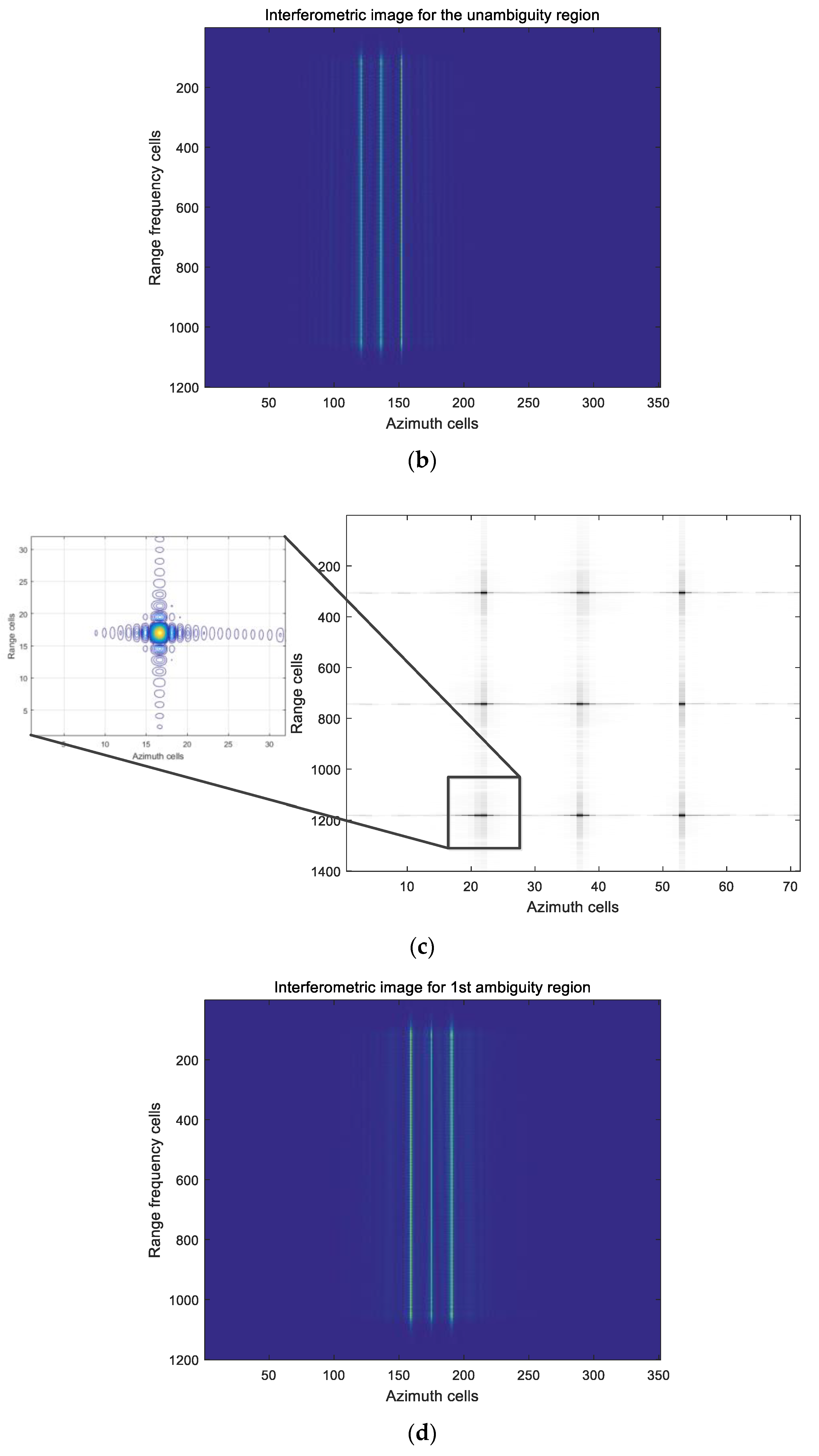
In this subsection, we consider the focus of points in different ambiguous regions. Therefore, we assume a scenario where the distributions of the points in different regions are different. Specifically, the distributions of the points in the unambiguous region, the 1 st ambiguous region, and the 2 th ambiguous region are presented in Figure 10a–c, respectively. From this simulation and its result, it is easy to judge whether the different regions can be separated and focused.
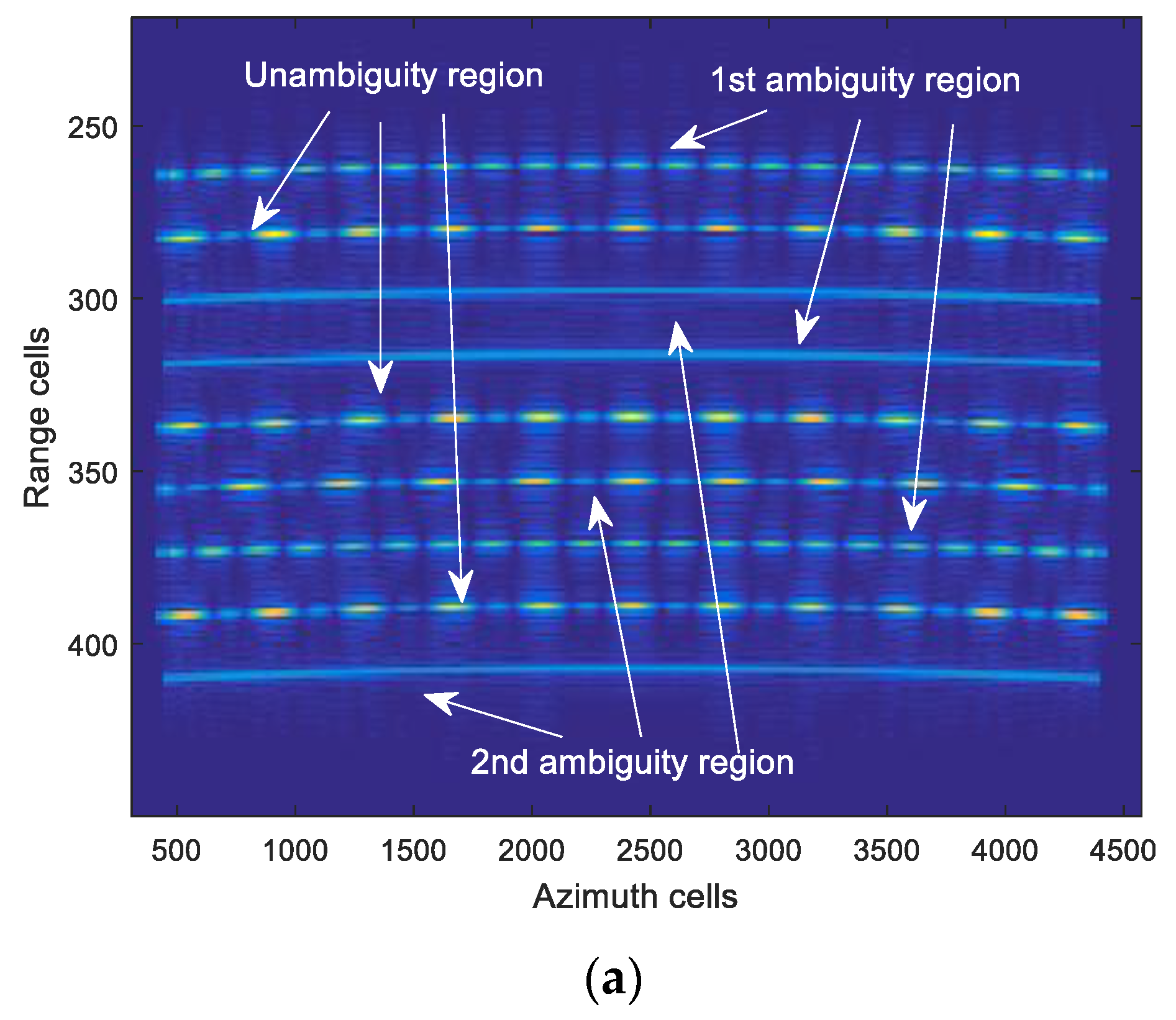
After range pulse compression, the echo data from the traditional SAR are provided in Figure 11a. For ease of visualization, the interval between the range cells of the targets in different regions is set to non-integer times of the maximum unambiguous distance. Therefore, the echo data in different range cells are not coincident for Figure 11a. When the echo data are processed directly by implementing traditional methods (i.e., the range-Doppler method or the chirp scaling method), the image results in the two-dimensional time domain are presented, as shown in Figure 11b. Obviously, only the points in the unambiguous regions are focused. This means that the unfocused points affect the image quality significantly and lead to a blurry scenario. Such consequences are intolerable in practice.
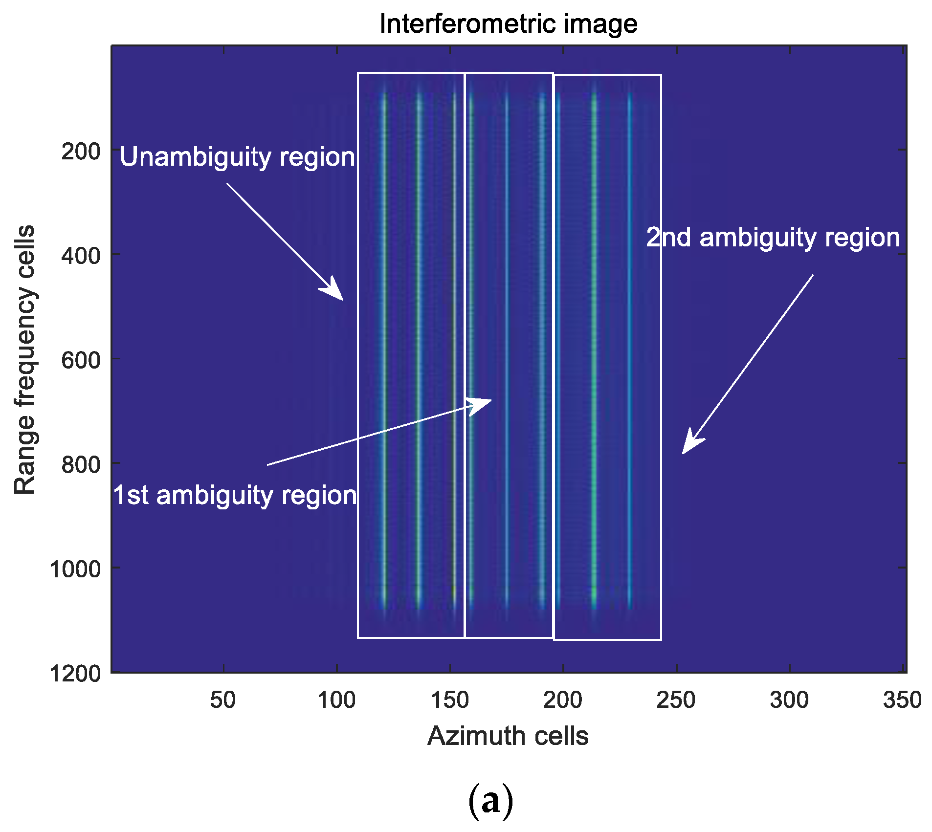
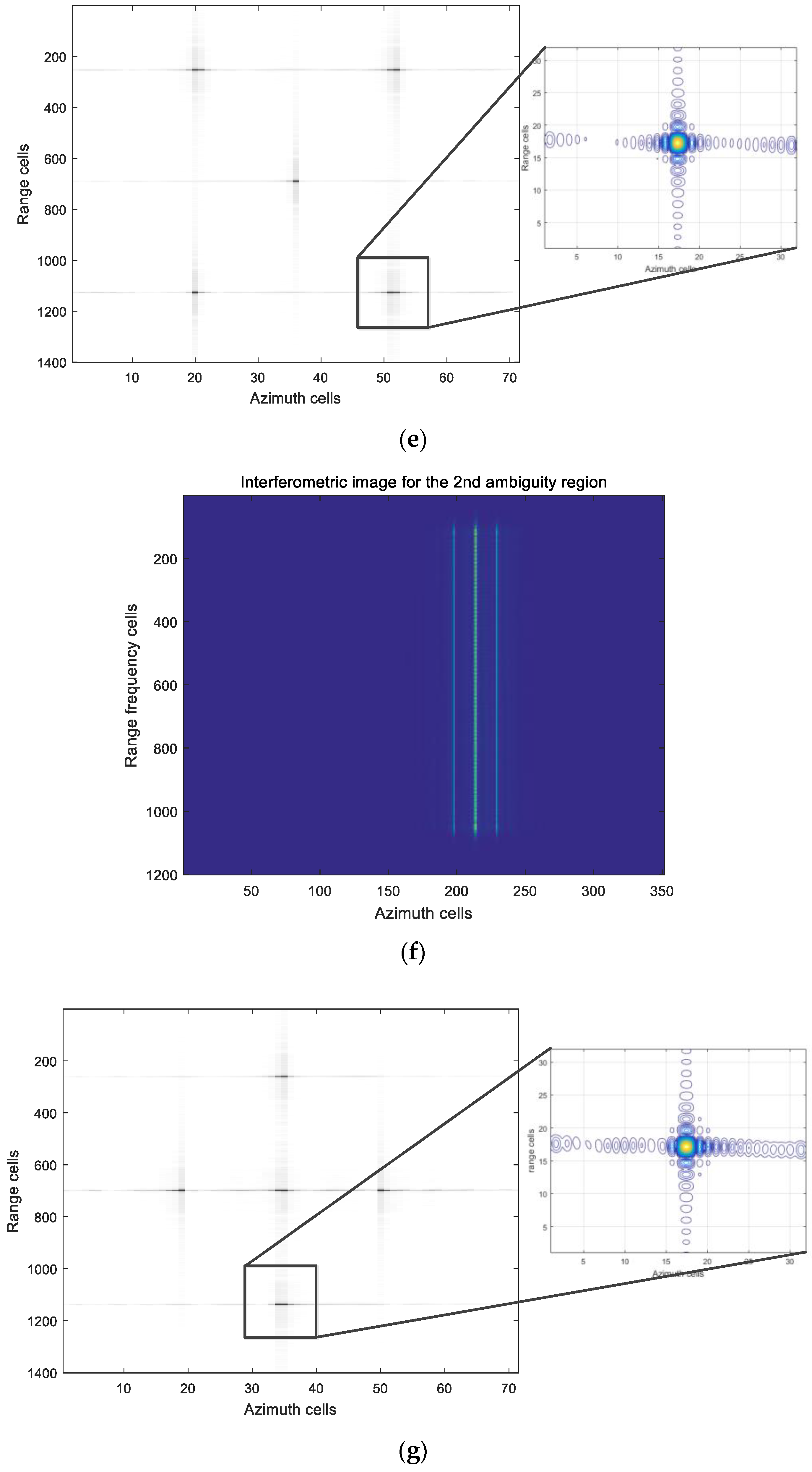
In DDMA-SAR, the interferometric image processed by the proposed method is shown in Figure 12a. Afterwards, we can process the interferometric data to separate it into the data of different regions by using the above designed passband time filters. Figure 12b,d,f are the separated interferometric images for the unambiguous region, the 1 st ambiguous region, and the 2 nd ambiguous region, respectively. As the two-order range frequency term has been removed, the points in the unambiguous region are focused by IFT for the range dimension in Figure 12c. Compared with Figure 11b and Figure 12c, the energy from other ambiguous regions has been suppressed, such that the focused points in Figure 12c are clearer than those in Figure 11b. Similarly, the images in Figure 12d,f are processed as Figure 12e,g. Then, the image results of the full swath are obtained. It indicates that the jamming signal is suppressed except for the signal of the desired range region, and the points in the desired range region can be focused. As a result, the range ambiguous echoes can be separated effectively into signals of three regions by the proposed mitigating range ambiguity method based on DDMA waveforms, and the full imaging results can be obtained.

5. Conclusions

A mitigating range ambiguity method based on the DDMA is proposed in this paper. Utilizing the DDMA waveform, the coupling term related to the Doppler frequency and the ambiguous range is generated. According to the characteristics of the coupling term, the echo data of different regions are distinguished by using IFT and interferometric processing. Meanwhile, by designing passband filters in the slow-time domain, the echo data of different ambiguous regions are extracted. Moreover, the images of different ambiguous regions are reconstructed to acquire all images. Using the method proposed in this paper, not only the continuous order ambiguity problem can be solved, but also all ambiguous regions can be imaged. Simulations and analysis illustrate the effectiveness of the proposed method.

Author Contributions

Conceptualization, Y.G. and G.L.; methodology, Y.G. and Y.W.; software and validation, Y.G. and J.L.; investigation, G.L.; data curation, Y.G.; writing—original draft preparation, Y.G.; writing—review and editing, Y.G., Y.W., G.L. and J.L.; supervision, Y.W.; funding acquisition, Y.W. and J.L. All authors have read and agreed to the published version of the manuscript.

Funding

This research was funded by the National Natural Science Foundation of China under Grant No. 51879221 and Grant No. 62170113.

Conflicts of Interest

We declare that we have no financial and personal relationships with other people or organizations that can inappropriately influence our work, there is no professional or other personal interest of any nature or kind in any product, service and/or company that could be construed as influencing the position presented in, or the review of, the manuscript entitled, “Mitigating Range Ambiguity Method Based on DDMA for SAR Systems”.

Appendix A. The Pre-Processed Operation for Different Channels
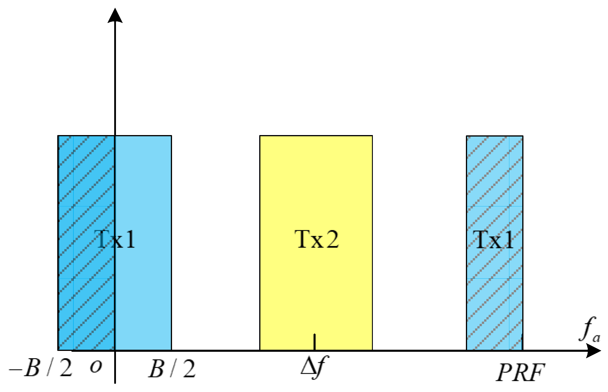
The diagram of different channel data is shown in Figure A1.
Figure A1. Diagram of the different channel data.
Remotesensing 14 05485 g0a1
From Figure A1, the definition domains of different channels are different (i.e., the blue rectangle and the yellow rectangle represent the first channel data and the second channel data, respectively). It can be seen that the definition domain of the first channel echo is f a , 1 B / 2 , B / 2 . However, the definition domain of the second channel data is f a , 2 B / 2 + f D D M A , B / 2 + f D D M A . Therefore, the different channel data cannot be processed directly by the interferometric method. Consequently, the part of the first channel data is extracted as
S 1 ( f a ) = exp j π f a 2 2 V 2 λ R k , l , B 2 + f D D M A / 3 , B 2 + f D D M A / 3
Then, using the three times interpolation operation to process the extracted data, we get
S 1 ( f a ) = exp j π 3 f a 2 2 V 2 λ R k , l , B 2 + f D D M A / 3 , B 2 + f D D M A / 3
Substituting f A = 3 f a into (A2), (A2) can be rewritten as
S 1 ( f a ) = exp j π f A 2 2 V 2 λ R k , l , B 2 + f D D M A , B 2 + f D D M A
It is observed that the definition domains of (A3) and the second channel data are the same. Thereafter, the data from the two channels can be processed by the interferometric method.

References

  1. Fan, H.; Zhang, L.; Zhang, Z.; Yu, W.; Deng, Y. On the processing of Gaofen-3 spaceborne dual-channel sliding spotlight SAR data. IEEE Trans. Geosci. Remote Sens. 2022, 60, 5202912. [Google Scholar] [CrossRef]
  2. Wang, Y.; Song, Q.; Wang, J.; Du, B.; Wang, P. A correction method to systematic phase drift of a high resolution radar for foreign object debris detection. Remote Sens. 2022, 14, 1787. [Google Scholar] [CrossRef]
  3. Djath, B.; Schulz-Stellenfleth, J.; Cañadillas, B. Study of coastal effects relevant for offshore wind energy using spaceborne synthetic aperture radar (SAR). Remote Sens. 2022, 14, 1688. [Google Scholar] [CrossRef]
  4. Chen, J.; Wang, K.; Yang, W.; Liu, W. Accurate reconstruction and suppression for azimuth ambiguities in spaceborne stripmap SAR images. IEEE Geosci. Remote Sens. Lett. 2017, 14, 102–106. [Google Scholar] [CrossRef]
  5. Zhao, B.; Zhang, Q. The staring mode properties and performance of geo-SAR satellite with reflector antenna. Remote Sens. 2022, 14, 1609. [Google Scholar] [CrossRef]
  6. Xiao, P.; Guo, W.; Wu, Y.; Liu, B. A comprehensive method of ambiguity suppression for constellation of geostationary and low earth orbit SAR. IEEE J. Sel. Top. Appl. Earth Obs. Remote Sens. 2020, 13, 3327–3335. [Google Scholar] [CrossRef]
  7. Zhang, S.; Xing, M.; Xia, X.; Zhang, L.; Guo, R.; Liao, Y.; Bao, Z. Multichannel HRWS SAR imaging based on range-variant channel calibration and multi-doppler-direction restriction ambiguity suppression. IEEE Trans. Geosci. Remote Sens. 2014, 52, 4306–4327. [Google Scholar] [CrossRef]
  8. He, F.; Dong, Z.; Zhang, Y.; Jin, G.; Yu, A. Processing of spaceborne squinted sliding spotlight and HRWS TOPS mode data using 2-D baseband azimuth scaling. IEEE Trans. Geosci. Remote Sens. 2020, 58, 938–955. [Google Scholar] [CrossRef]
  9. Raney, R.K.; Freeman, A.; Jordan, R.L. Improved range ambiguity performance in quad-pol SAR. IEEE Trans. Geosci. Remote Sens. 2012, 50, 349–356. [Google Scholar] [CrossRef]
  10. Anderson, J.M.; Temple, M.A.; Brown, W.M.; Crossley, B.L. A nonlinear suppression technique for range ambiguity resolution in pulse Doppler radars. In Proceedings of the 2001 IEEE Radar Conference (Cat. No.01CH37200), Atlanta, GA, USA, 3 May 2001. [Google Scholar]
  11. Mittermayer, J.; Martinez, J.M. Analysis of range ambiguity suppression in SAR by up and down chirp modulation for point and distributed targets. In Proceedings of the 2003 IEEE International Geoscience and Remote Sensing Symposium, Toulouse, France, 21–25 July 2013; pp. 1013–1015. [Google Scholar]
  12. Xiao, P.; Liu, M.; Guo, W.; Yu, J. The range ambiguity suppression based on amplitude modulation chirp. In Proceedings of the 2019 IEEE International Geoscience and Remote Sensing Symposium, Yokohama, Japan, 28 July–2 August 2019. [Google Scholar]
  13. Wang, H.; Zhang, Y.; Xu, J.; Liao, G.; Zhu, S. Range ambiguity suppression in a synthetic aperture radar using pulse phase coding and two-pulse cancellation. Int. J. Remote Sens. 2018, 39, 6525–6539. [Google Scholar] [CrossRef]
  14. Wang, H.; Zhang, Y.; Xu, J.; Liao, G.; Zeng, C. Study on coding scheme for space-pulse-phase-coding-based high-resolution and wide-swath SAR imaging. Int. J. Remote Sens. 2020, 41, 7186–7200. [Google Scholar] [CrossRef]
  15. Dall, J.; Kusk, A. Azimuth phase coding for range ambiguity suppression in SAR. In Proceedings of the 2004 IEEE International Geoscience and Remote Sensing Symposium, Anchorage, AK, USA, 20–24 September 2004. [Google Scholar]
  16. Zhang, Y.; Wang, W.; Deng, Y.; Yu, W.; Zhang, Z.; Zhao, P.; Wang, R. Quadratically constrained ambiguity suppression algorithm for APC/multichannel SAR systems with nonuniform spatial sampling. IEEE Trans. Geosci. Remote Sens. 2021, 59, 1319–1330. [Google Scholar] [CrossRef]
  17. Dai, C.; Wang, T.; Zhao, B. Concept of Geo-SAR system with dbf antenna and range ambiguity performance discussion. In Proceedings of the IET International Radar Conference (IET IRC 2020), Online Conference, 4–6 November 2020. [Google Scholar]
  18. Ryu, J.; Yi, D.; Kim, S.; Yoon, G. Suppression of range ambiguity in spaceborne SAR with elevation beam pattern mask design. IEEE Geosci. Remote Sens. Lett. 2021, 19, 4008605. [Google Scholar] [CrossRef]
  19. Villano, M.; Krieger, G.; Moreira, A. Staggered SAR: High-resolution wide-swath imaging by continuous PRI variation. IEEE Trans. Geosci. Remote Sens. 2014, 52, 4462–4479. [Google Scholar] [CrossRef]
  20. Riché, V.; Méric, S.; Baudais, J.; Pottier, É. Investigations on OFDM signal for range ambiguity suppression in SAR configuration. IEEE Trans. Geosci. Remote Sens. 2014, 52, 4194–4197. [Google Scholar] [CrossRef] [Green Version]
  21. Wang, W.Q.; Shao, H.Z.; Cai, J.Y. Range angle dependent beamforming by frequency diverse array antenna. Int. J. Antennas Propag. 2012, 2012, 760489. [Google Scholar] [CrossRef] [Green Version]
  22. Wang, C.; Xu, J.; Liao, G.; Xu, X.; Zhang, Y. A range ambiguity resolution approach for high-resolution and wide-swath SAR imaging using frequency diverse array. IEEE J. Sel. Top. Signal Process 2017, 11, 336–346. [Google Scholar] [CrossRef]
  23. Chen, Z.; Zhang, Z.; Zhou, Y.; Zhao, Q.; Wang, W. Elevated frequency diversity array: A novel approach to high resolution and wide swath imaging for synthetic aperture radar. IEEE Geosci. Remote Sens. Lett. 2020, 19, 1–5. [Google Scholar] [CrossRef]
  24. Blunt, S.D.; Mokole, E.L. Overview of radar waveform diversity. IEEE Aerosp. Electron. Syst. Mag. 2016, 31, 2–42. [Google Scholar] [CrossRef]
  25. Sun, H.; Brigui, F.; Lesturgie, M. Analysis and comparison of MIMO radar waveforms. In Proceedings of the 2014 International Radar Conference, Lille, France, 13–17 October 2014. [Google Scholar]
  26. Mecca, V.F.; Krolik, J.L.; Robey, F.C. Beamspace slow-time MIMO radar for multipath clutter mitigation. In Proceedings of the 2008 IEEE International Conference on Acoustics, Speech and Signal Processing, Las Vegas, NV, USA, 31 March 2008–4 April 2008. [Google Scholar]
  27. Rabideau, D.J. Doppler-offset waveforms for MIMO radar. In Proceedings of the IEEE Radar Conference, Kansas City, MO, USA, 23–27 May 2011; pp. 965–970. [Google Scholar]
  28. Rabideau, D.J. MIMO radar waveforms and cancellation ratio. IEEE Trans. Aerosp. Electron. Syst. 2012, 48, 1167–1178. [Google Scholar] [CrossRef]
  29. Li, F.; He, F.; Dong, Z.; Wu, M.; Zhang, Y.; Sun, Z. Blind velocities mitigation for ddma mimo gmti radar via multi-frequency signals. In Proceedings of the IEEE 2018 19th International Radar Symposium (IRS), Bonn, Germany, 20–22 June 2018; pp. 1–9. [Google Scholar]
  30. Rossum, W.V.; Anitori, L. Doppler ambiguity resolution using random slow-time code division multiple access MIMO Radar with sparse signal processing. In Proceedings of the 2018 IEEE Radar Conference (RadarConf18), Oklahoma City, OK, USA, 23–27 April 2018; pp. 1–5. [Google Scholar]
  31. Xu, F.; Vorobyov, S.A.; Yang, F. Transmit Beamspace DDMA based automotive MIMO radar. IEEE Trans. Veh. Techn. 2022, 71, 1669–1684. [Google Scholar] [CrossRef]
  32. Wang, W. Mitigating range ambiguities in high-PRF SAR with OFDM waveform diversity. IEEE Geosci. Remote Sens. Lett. 2013, 10, 101–105. [Google Scholar] [CrossRef]
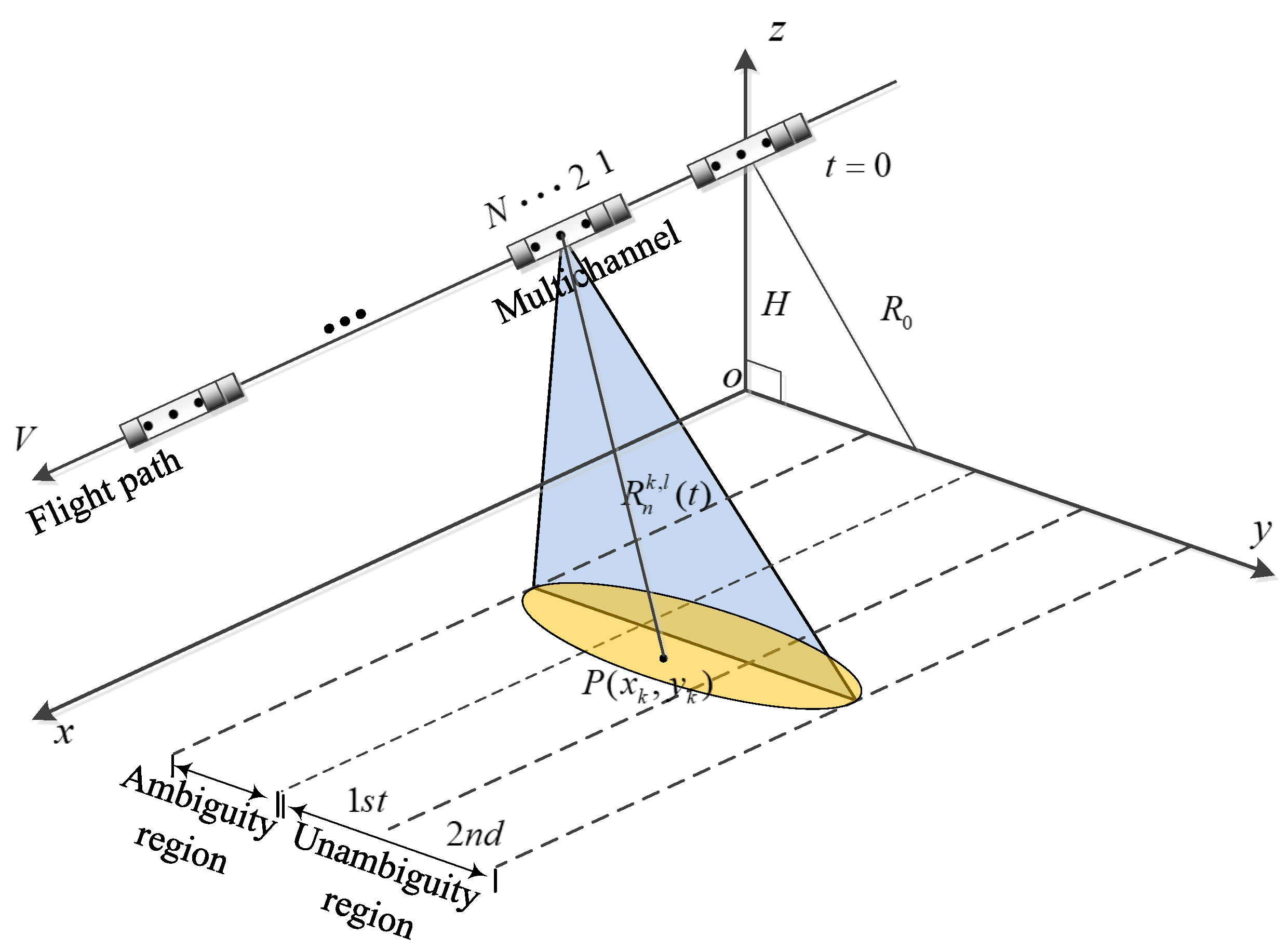
Figure 1. Multi-channel SAR system.
Remotesensing 14 05485 g001
Figure 2. The echo signals of different ambiguous regions.
Remotesensing 14 05485 g002
Figure 3. Block diagram of the echo data separated by the bandpass filters in DDMA waveforms.
Remotesensing 14 05485 g003
Figure 4. Echo data in a slow-time domain using the proposed method.
Remotesensing 14 05485 g004
Figure 5. Echo data in the slow-time domain using the proposed method when illumination time is longer than the shifting time.
Remotesensing 14 05485 g005
Figure 6. Block diagram of the proposed method.
Remotesensing 14 05485 g006
Figure 7. Range-ambiguity-to-signal ratio versus PRF: (a) the up-down chirp method; (b) the OFDM method; (c) the proposed method; (d) different methods for all ambiguous regions.
Remotesensing 14 05485 g007
Figure 8. Interferometric images of different methods: (a) interferometric image using the traditional MISO-SAR; (b) the elevation slice diagram of the interferometric image using the traditional MISO-SAR; (c) interferometric image using the DDMA-SAR; (d) the elevation slice diagram of the interferometric image using the DDMA-SAR.
Remotesensing 14 05485 g008aRemotesensing 14 05485 g008b
Figure 9. Designed passband time filter.
Remotesensing 14 05485 g009
Figure 10. Positions of the point targets for different regions: (a) positions of the point targets in the unambiguous region; (b) positions of the point targets in the 1 th ambiguous region; (c) positions of the point targets in the 2 nd ambiguous region.
Remotesensing 14 05485 g010aRemotesensing 14 05485 g010b
Figure 11. Results of the traditional method: (a) echo data after the range pulse compression; (b) echo data after the azimuth compression.
Remotesensing 14 05485 g011aRemotesensing 14 05485 g011b
Figure 12. Results using the proposed method: (a) interferometric image using the proposed method; (b) interferometric image of the unambiguous region after passband time filter; (c) focused result of the unambiguous region; (d) interferometric image of the 1 st ambiguous region after passband time filter; (e) focused result of the 1 st ambiguous region; (f) interferometric image of the 2 nd ambiguous region after passband time filter; (g) focused result of the 2 nd ambiguous region.
Remotesensing 14 05485 g012aRemotesensing 14 05485 g012bRemotesensing 14 05485 g012c
Table 1. Parameters for the spaceborne SAR operation.
ParametersValues
Number of transmitted elements N 2
Radar platform velocity V 7100 m/s
Height of the radar platform H 800 km
Carrier wavelength λ 0.07 m
Inter-element spacing d 0.14 m
Bandwidth B 50 MHz
Sampling frequency f s 80 MHz
Pulse repetition frequency P R F 4500 Hz
Publisher’s Note: MDPI stays neutral with regard to jurisdictional claims in published maps and institutional affiliations.