Article

A W-Band Active Phased Array Miniaturized Scan-SAR with High Resolution on Multi-Rotor UAVs

National Key Laboratory of Microwave Imaging Technology, Aerospace Information Research Institute, Chinese Academy of Sciences, Beijing 100094, China
*
Author to whom correspondence should be addressed.
Remote Sens. 2022, 14(22), 5840; https://doi.org/10.3390/rs14225840
Submission received: 22 September 2022 / Revised: 14 November 2022 / Accepted: 15 November 2022 / Published: 18 November 2022

Abstract

:
The smart unmanned aerial vehicle (UAV) with a mini-SAR payload provides an advanced earth observation capability for target detection and imaging. Simiar to large-scale SAR, mini-SAR also has an increasing requirement for high resolution and wide swath. However, due to the low cruising altitude of UAVs, small coverage angles in the direction range, and the insufficient operating range of mini-SAR, expanding the swath has become an urgent problem for mini-SAR. To solve this problem, this paper proposes a W-Band active phased array miniaturized SAR (APA mini-SAR), whose scanning capacity has been proven on the multi-rotor UAV platform. Many efforts, including the novel active phased array antenna scheme, the sparse triangular arrangement of antenna elements, the wideband chirp source, and the three-dimensional integration technology, have been made to develop this APA mini-SAR for the first time in the W-Band. The volume of this APA mini-SAR is 69 × 82 × 87 mm3, with a weight of 600 g. Combined with a new motion compensation strategy and the ω-k imaging algorithm, the focused image is finally obtained. Experiments have been conducted, and the results indicate that this APA mini-SAR has a resolution of 4.5 cm, the imaging swath is three times that of the traditional single-channel mini-SAR, and the operating range is increased to 800 m.

1. Introduction

Synthetic aperture radar (SAR) uses the motion of the radar antenna over a target region to provide a finer spatial resolution than conventional radars. The finer resolution is attributed to the SAR’s larger synthetic antenna aperture, which allows SAR to create high-resolution images with relatively small physical antennas compared with conventional radars. Based on this advantage and the rapid development of drones and UAV-borne, several new types of SARs have been developed [1,2,3,4]. The giant plane-borne, satellite-borne, and UAV-borne radars could obtain complementary information in extended operating conditions at the cost of weight, volume, and power consumption. However, small drones or UAVs could carry various SARs for flexible remote sensing and measurements.
Currently, there are many small UAV-borne SAR applications in scientific, agricultural, and environmental monitoring and sensing [5,6,7,8,9]. The advantages of UAV-borne SAR motivated further research toward the development of new mini-SAR techniques. To meet the requirements of small UAVs for SAR, researchers have made many efforts to achieve mini-SAR with a lighter weight, smaller volume, and lower power consumption.
To provide a suitable SAR for smart UAVs, a mini-SAR sensor was introduced in [10] in 2021, which is our previous study. The overall objective was to design a miniaturized SAR that can be deployed on a multi-rotor UAV platform to achieve a state-of-the-art imaging resolution of about 4.5 cm and a whole-system size of only 67 × 60 × 50 mm3, and a weight of 400 g was obtained. Though imaging resolution is very prominent, the imaging swath is only about 308 m. In [11], the researchers developed a low-cost, drone-borne vehicular frequency-modulated continuous-wave (FMCW) SAR operating at 77 GHz. The SAR system was mounted on a DJI multi-rotor drone for testing, and a cross-range resolution of 2 cm was achieved within a short range. In [12,13], an early example of a highly miniaturized Ka-band FMCW SAR sensor called MISAR was proposed for small UAVs. Through the development of two-generation systems, the design goals with respect to range, resolution, size, weight, and prime power has been fully achieved.
Limited by volume and isolation, the transmit power of mini-SAR cannot be too high. For this reason, mini-SAR often uses large antennas to improve the imaging range, which indicates that mini-SAR has a narrow beam width in the range direction. This will cause a narrow swath, and the low cruising altitude of UAVs further makes mini-SAR fall into a narrow swath. For example, the maximum imaging range in [10,11] is about 600 m and 100 m, respectively, which will cause a narrow imaging swath according to the geometric relationship. As a result, the maximum imaging swath coverage is only about 400 m and 43 m, respectively. The imaging range and swath coverage are far from the Airborne SAR level [14,15], and this does not meet the needs of surveying and mapping.
Along with the increase in high resolution and wide swath imaging requirements, some large-scale SARs with HRWS have been developed by using the phased array SAR [16], frequency diverse array (FDA) [17], digital beamforming (DBF) [18], and MIMO SAR [19,20]. Studies have shown that the contradiction of PRF design can be alleviated through an array transceiver to expand the swath. Compared with the centralized transmitter SAR, the array radar technology can provide a higher transmitting power and beam scanning ability, which has been applied to improve the imaging range and expand the swath [21,22]. In particular, the mature phased array radar, where the transmit and receive amplifiers can be distributed to each element of the array, reduces the noise figure and increases the total transmit power, leading to improved sensitivity and longer operating ranges [23]. At the same time, phased array SAR can perform beam scanning in the range direction, which can obtain multiple strip images by time-sharing. For example, in [22,24], TerraSAR-X was introduced in 2003. In this system, SAR is equipped with active phased array antennas hosting many transmit/receive modules to electronically generate various antenna beam steering in the azimuth and elevation direction, thus covering a wide look angle range. Therefore, phased array SARs can well solve the problems of short imaging range and narrow swath coverage. Although phased array technology is not widely used in mini-SAR, it may become an effective way to solve the problems of a short range and a narrow swath in mini-SAR.
However, for a W-Band phased array radar operating in the FMCW mode, there are many design difficulties. Firstly, the W-Band has an extremely short wavelength, so the array element spacing of conventional array antennas is very small, which brings difficulties to phased array antenna integration. To make matters worse, though the integrated TR chip can alleviate the difficulty of integration, there is no MMIC TR chip available for the FMCW radar in W-Band. Meanwhile, the link and space loss of W-Band signals increases as the frequency gets higher, which also makes the design of an active phased array antenna difficult to realize.
In this paper, a W-Band APA mini-SAR system for small UAVs is introduced in detail, which provides a new method for earth observation. The main research work focuses on improving the imaging range and swath coverage of mini-SARs by using the phased array technology. To this end, the W-Band miniaturized active phased array antenna (APA) and integration technology with a high circuit density have been studied. Meanwhile, a wideband chirped source based on the analog phase-locked loop is proposed to generate the broadband transmit signal. Then, combined with the novel motion compensation approach, an image with a high resolution and a wide swath can be achieved.
The structure of this paper is organized as follows. In Section 2, the overall scheme of this APA mini-SAR is introduced, including the active phased array mini-SAR architecture and the system performance. In Section 3, some key technologies are described. Firstly, the integration strategy for realizing small volume and lightweight is introduced. Secondly, the design method for the LFM waveform generator based on the analog phase locked loop is illustrated, and the frequency nonlinearity is analyzed in detail. Thirdly, the design method of the active phased array antenna is described, with an emphasis on the architecture of reducing phase shift loss and the arrangement of antenna elements. Fourthly, a novel motion compensation method is briefly described. To validate the proposed APA mini-SAR, an imaging experiment is introduced in Section 4, and the imaging resolution, swath, and response of the trihedral corner reflector are analyzed in detail. The comparison between the proposed APA mini-SAR and the existing mini-SARs indicates that the APA mini-SAR has obvious advantages in volume, weight, and imaging range, as well as the ability to wide swath images. Finally, the research work is summarized in Section 5.

2. W-Band SAR System Scheme

2.1. Active Phased Array Mini-SAR Architecture

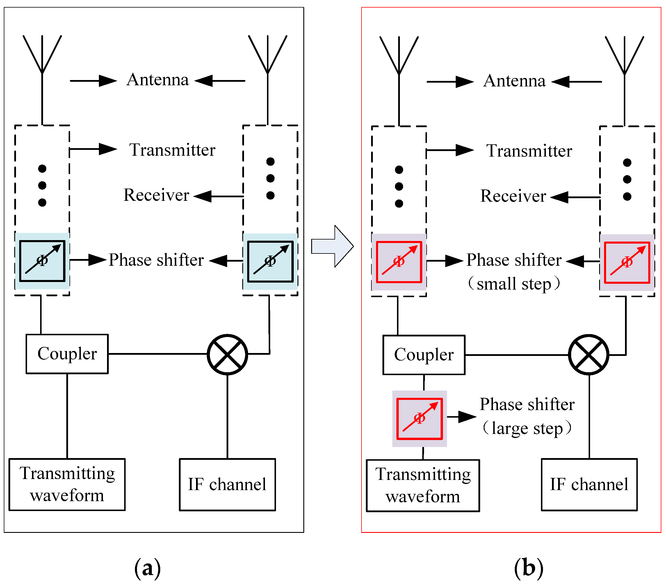
The conventional mini-SAR is generally based on the FMCW transceiver and usually uses a single transmitter and a single receiver. Meanwhile, DAC/DDS combined with a millimeter wave mixer is used to generate the transmission waveform [25]. Since there is no dedicated TR chip for the FMCW phased array, the traditional scheme uses phase shifters of 360 degrees at the transmitter and receiver, respectively, resulting in complex circuits and high-power consumption. Their performance deteriorates seriously during circuit integration, especially in the W-Band. In this section, a novel APA mini-SAR scheme is proposed to design a UAV mini-SAR, which reduces the number of phase shifters by sharing phase shifters, as shown in Figure 1.
This APA mini-SAR contains a crystal oscillator working at 50 MHz which is used as the reference clock (Ref. Clock) for the SAR system, a linear frequency modulation (LFM) source that is used to generate transmission waveforms, two active phased array antennas containing power amplifiers (PA), low noise amplifiers (LNA), and phase shifters (PS) which are used for beam scanning and amplitude control of transmitted and received W-Band signals, an intermediate frequency (IF) receiver which is used for gain control of low-frequency received signals, and digital modules including an analog-to-digital converter (ADC) and a solid-state disk (SSD) which realize the acquisition and storage of radar echo data. The LFM source is composed of a voltage-controlled oscillator (VCO), a phase and frequency detector, a frequency divider (1/N), a loop filter (LF), a multiplier (×8), and a phase shifter (PS).
In this circuit design, commercial RF and digital electronic components are widely used. For example, ADF4169 produced by Analog Devices Inc. (Norwood, USA) is used as a PFD, and HMC732 is used as a VCO. To achieve low noise and high transmission power, InP and GaAs components are, respectively, applied to TR, and the phase shifter is a custom device designed by Complementary Metal-Oxide-Semiconductor (CMOS) technology. In the digital circuit, AD9269 and XILINX K7 are used for data quantization and processing.
To facilitate the miniaturization design, the method of frequency modulation continuous wave transceiver is adopted in this study. One advantage of this method is that the de-chirp can be used in the receiver. De-chirp is a common method for wideband radar chirp signals by using a millimeter wave mixer, which can decrease the bandwidth of the input signal. Meanwhile, due to the lower echo frequency, the sampling rate of ADC and the data volume of SAR are greatly reduced, which is beneficial to the design of digital systems. The second advantage of this method is that the LFM signal waveform can be generated by phase-locked technology. Compared with the traditional waveform generation scheme of miniaturized SAR, PLL can directly generate a high-frequency broadband LFM signal and greatly simplify the design of the system clock [26,27]. For example, just a 50 MHz crystal oscillator can satisfy the reference signal demand of the digital module and the analog circuit at the same time. However, in the traditional waveform generation scheme, multiple local oscillator signals and reference signals for DAC need to be synthesized to realize the up-conversion and down-conversion of the signal. In addition, the transmit signal generated by PLL has low phase noise and good spurious suppression, which is the basic condition for high-quality imaging. Another advantage of the frequency modulation continuous wave transceiver is that the phased array design of the FMCW radar can use the transceiver shared phase shifter (PS) to reduce the number of phase shifters. Compared with the microwave phase shifter, the phase shifter has a larger loss in the W-Band [28,29]. Therefore, reducing the number of phase shifters is beneficial for decreasing the power consumption of the system. This design will be introduced in detail in Section 3 of this paper.
Other new methods such as waveguide horn array antennas and sparse array technology have also been applied to this mini-SAR. Attributed to the above design, this APA mini-SAR has a simple circuit structure and a low system power consumption, which is also conducive to miniaturization.

2.2. System Performance

Table 1 shows the performance parameters of the APA mini-SAR system. This table describes the main operating parameters of the system, including the center frequency, signal bandwidth, waveform, maximum imaging range, scanning beams, resolution, weight, etc. According to these system parameters, the noise equivalent sigma zeros (NESZ), a key parameter of SAR imaging quality, is simulated.
For the side-view stripe SAR, the NESZ calculation formula is shown in Equation (1).
N 0 = 2 ( 4 × π ) 3 R 3 V a k T λ 3 G t G r P a v ρ r g k s
where N0 represents NESZ, R denotes the imaging range, Va denotes the moving velocity of SAR, k denotes the Boltzmann constant, T denotes the equivalent noise temperature of the receiver, λ denotes the operation wavelength of SAR, Gt and Gr denote the gains of transceiver antennas, Pav denotes the average transmission power, ρ r g denotes the ground resolution in the range direction, ks denotes the loss of the system.
Figure 2 shows the simulation results of NESZ for this APA mini-SAR under a downward viewing angle of 30° and a flight altitude of 500 m, and the horizontal axis and the vertical axis represent the slant distance and NESZ value, respectively. Within 1000 m, the NESZ is lower than 24.0 dB, which can meet the requirement of high SNR imaging for the earth observation according to experience.
The ground range resolution represented by ρ r g in the NESZ formula can be derived from the bandwidth of the transmitted signal. When the downward look angle is 30°, the ground range resolution is about 4.3 cm.
In the azimuth direction, the azimuth resolution denoted by ρ a z can be derived from the azimuth antenna size for the orthogonal strip imaging mode, as shown in Equation (2).
ρ a z = D 2
where D is the antenna aperture size in azimuth. In the proposed APA mini-SAR, D is about 5.0 cm. Therefore, according to theoretical calculation, the azimuth resolution of this system is 2.9 cm, and the Taylor weighting coefficient is 0.86. In the actual experiment, the resolution along the range and azimuth will inevitably deteriorate, but experiments have proved that this deterioration is so small and does not affect the excellent imaging resolution.

3. Key Technologies of the APA Mini-SAR

3.1. Integration Strategy

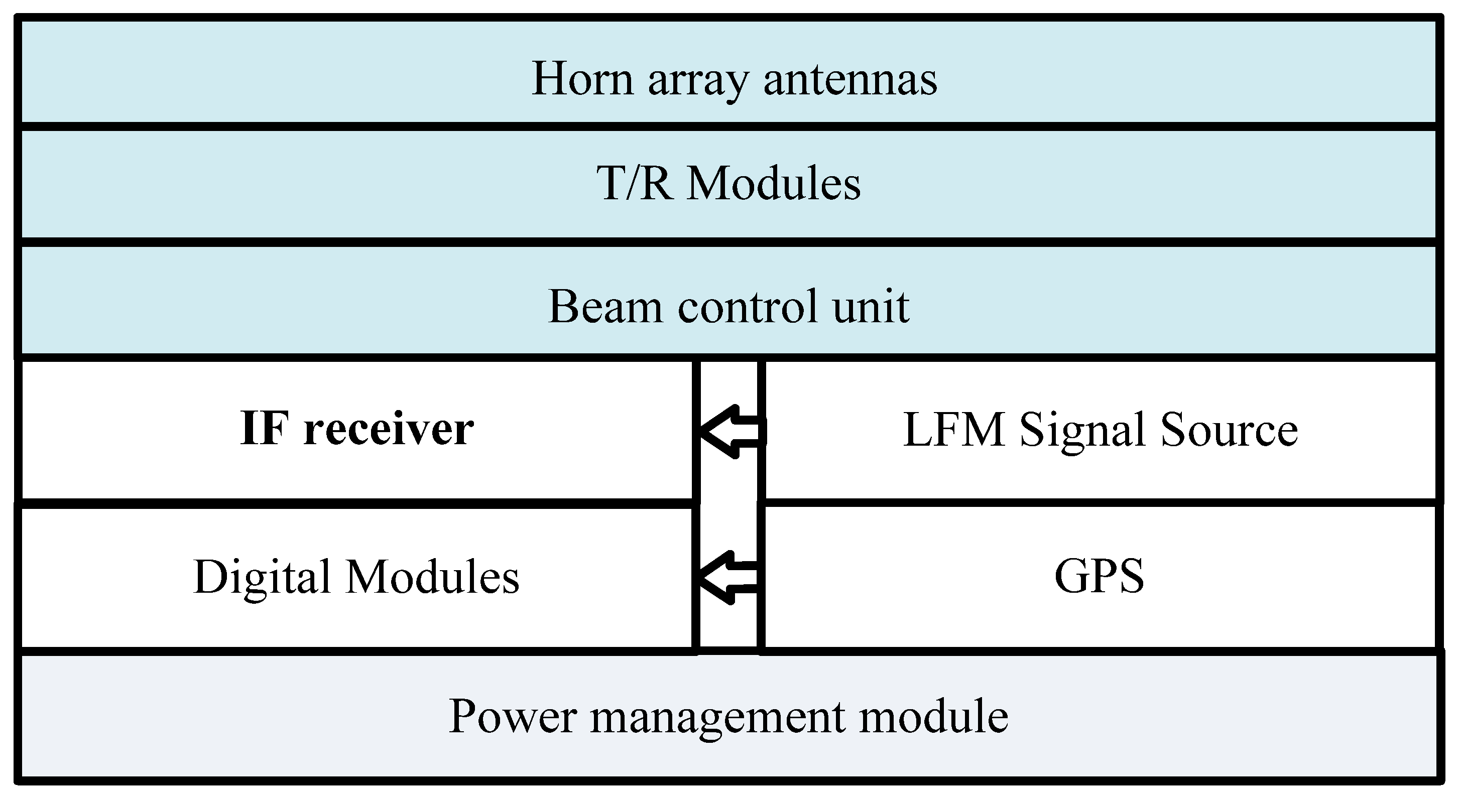
Figure 3 shows the diagram of the integration strategy used in the APA mini-SAR. This mini-SAR adopts the three-dimensional integration strategy, which is realized by vertically stacking the millimeter-wave, RF, and digital circuit modules, and the vertical interconnection is designed between these circuit modules.
The top of the cube block is the active phased array antenna, including the T/R modules, horn array antennas, and beam control unit. The array antennas and TR modules are connected by a vertical transition waveguide port, which effectively reduces the connection loss. The antenna is fixed by using screws and conductive glues.
The miniaturized radar is usually integrated based on printed circuit board (PCB) technology and a combination of multiple cavity modules. In this way, the system integration is improved by continuously increasing the density of active chips and passive components. Since the components are installed on the plane layout, the two-dimensional plane integration method cannot achieve high-density integration.
In the millimeter wave band, the compact circuit layout indicates that the signal trace length can be reduced, which will alleviate the overall loss of the system.
Unlike two-dimensional integration, three-dimensional (3D) integration increases the dimension of circuit wiring and assembly, which leads to a compact design and reduces the circuit area and volume [30,31,32]. Therefore, the 3D integration strategy is applied to this mini-SAR to achieve miniaturization and lightweight.
In this packaged 3D configuration, the following main design steps are taken.
Firstly, several circuit modules, such as the antenna, IF receiver, TR module, digital module, and power management module, are divided according to frequency bands to achieve an excellent EMC design. Each module has an independent shielding structure, which avoids mutual interference between different frequencies.
Secondly, according to the function of the module, each module is reasonably assembled. The phased array antenna is arranged at the top of the mini-SAR, the signal generator and IF receiver are arranged in the middle, and the digital module and power management module are designed at the bottom.
Thirdly, high-frequency and low-frequency DC signals are interconnected through vertical connection technology. For millimeter wave signals, this method is necessary, which can effectively reduce transmission loss, such as signal transmission loss between the antenna and transceiver.
Finally, as an important part of 3D integration, thermal and stress design is conducted, and simulation is carried out. The heat dissipation effect and structural stress of this mini-SAR are analyzed. Then, the layout of the high-power chip is optimized to improve the heat dissipation efficiency and pay attention to the stress of the die chip.

3.2. LFM Signal Generator Based on Analog Pll

The proposed mini-SAR scheme uses an analog phase-locked loop to generate wideband chirp signals, which brings some advantages to the miniaturization design of this system and also some disadvantages to the pulse phase stability, frequency linearity, and phase noise. This is determined by the circuit characteristics of the analog PLL. To achieve a high-performance transmission waveform, the method of generating LFM signals by PLL is studied in depth, with a focus on optimizing the loop parameters of PLL. Firstly, a mathematical model of the LFM source circuit based on PLL is proposed and established.
In this paper, the wideband PLL applies the active integral loop filter. In fact, PLL is not ideally phase locked, but there is a phase error between the reference clock and the output signal, which can be expressed by the phase error transfer function, as shown in Equation (3).
H e ( s ) = s 2 s 2 + 2 s ξ ω n + ω n 2
where ω n = K 0 K d N τ 1 , ξ = ω n 2 τ 2 , ω n is the angular velocity of the signal, ξ is the damping factor, τ1 and τ2 are the time constants of active filters, K0 is the tuning gain for PLL VCO, Kd is the phase gain, and N is the PLL multiple.
The frequency division ratio of the PLL will be controlled in real time so that the output of the PLL is a linear frequency modulation signal. This can be equivalent to the case that the input of the PLL is a continuous linear frequency modulation signal. For continuous chirp signals, the PLL input signals will exhibit phase step excitation and chirp excitation, respectively. The exciting signal is expressed in Equation (4).
θ i = S b t w p + S i n p
where S b t w p and S i n p represent the phase step excitation and chirp excitation, respectively. Then, the exciting phase θi can be expressed in Equation (5).
θ i = θ 0 u ( t ) + k π t 2 u ( t )
where k (Hz/s) denotes the chirp rate, u(t) denotes the step signal, and θ0 denotes the phase step. The Laplace transform from Equation (6) can be obtained as shown in Equation (6).
θ ( s ) = k π s 3 + θ 0 s
Based on this, in the continuous wave chirp mode, the phase error of PLL can be given by Equation (7).
θ e ( s ) = H e ( s ) θ ( s ) = s 2 s 2 + 2 s ξ ω n + ω n 2 ( θ 0 s + k π s 3 )
As deduced from Equation (7), to obtain an ideal LFM signal, a smaller θe is required, which can be achieved by optimizing the τ1, τ2, and k iteratively.
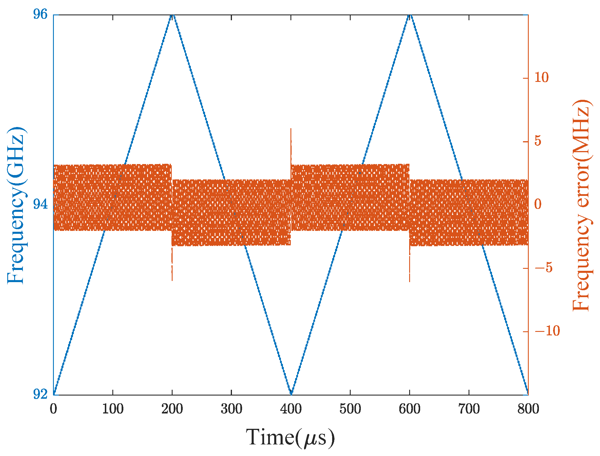
Before designing the LFM source circuit, the simulation was conducted, and the results are shown in Figure 4. It can be seen from this figure that the maximum frequency deviation from the linear one is about 3.24 MHz, and the RMS value is less than 1.45 MHz. According to further measured linearity measurement and previous experience, the LFM source design is sufficient to meet the requirements.
The measured results also show that when the output signal is switched between positive and negative frequency modulation, the PLL has feedback overshoot, resulting in large frequency errors. However, the overshoot occurs at the beginning of the pulse and takes a short time, usually dozens of nanoseconds. The collected data at the beginning of each frame can be directly cut off to alleviate the impact of the overshoot on other signals so that the system performance will not be affected.
The stable phase between pulses is important for azimuth signal synthesis and imaging processing in SAR systems, which indicates that the phase shift between multiple pulses in the synthetic aperture time must be small enough. Once the PLL is not locked, the relative phase of the output signal will be a runaway. Therefore, a lot of research work has been conducted on the design of loop bandwidth and the selection of voltage-controlled oscillators (VCO), which aims to ensure that the PLL always works in the locked state to achieve a stable phase between pulses. Finally, phase stability of fewer than 3 degrees in 5 min is obtained, as shown in Figure 5.
In this result, the maximum error of the random phase is about 5.1 degrees, and the RMS value of phase stability is less than 1.7 degrees. Additionally, there is a slow phase drift, which is caused by the frequency drift of the reference source and the temperature change of the system, as shown by the red line in Figure 5. The phase drift will affect the quality of the pulse compression in the azimuth direction. However, the phase drift of this LFM source is small enough, and the synthetic aperture time of this APA mini-SAR is short, i.e., a few seconds, so the system performance will not be affected.
Due to the technical limitations of the PLL waveform generation method, it is impossible to generate a completely ideal LFM signal, which indicates that the generated transmission signal has frequency nonlinearity. In the FMCW system, the nonlinear FM signal as the transmitted waveform will affect the pulse compression quality and deteriorate the imaging performance. Therefore, the mini-SAR system has high requirements for the frequency linearity of the transmitting waveform. Frequency nonlinearity is directly related to the frequency error, which is given by Equation (8).
F n o n l = f e B W
where F n o n l is the frequency nonlinearity, f e is the frequency error, and BW is the signal bandwidth.
The frequency error can be obtained by time–frequency analysis. Firstly, a high-speed oscilloscope is used to collect the generated signal. Then, the short-time Fourier transform method is applied, and the frequency error after data processing is calculated, as shown in Figure 6a. It can be seen that the worst frequency error is about 3.7 MHz, which is almost consistent with the simulation result of 3.24 MHz. Meanwhile, the frequency nonlinearity index can be calculated. The results are presented in Figure 6b, indicating that the worst frequency linearity is 9.2 × 10⁻⁴, which is also consistent with expectations.
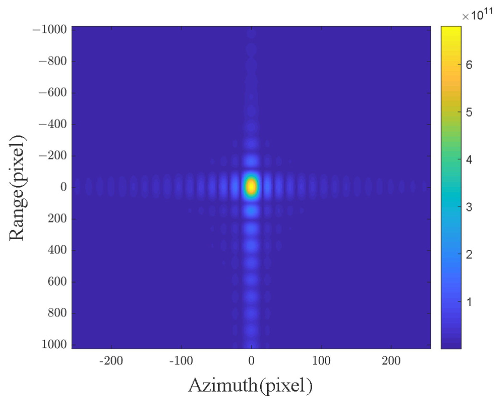
In addition, pulse compression quality analysis of the phase-locked output signal is necessary to ensure high-quality imaging of the mini-SAR. Thus, a point target experiment for the imaging triangular reflector was designed and carried out in a microwave anechoic chamber. The target reflectance echo was acquired and stored. Then, digital signal processing was performed, and the results are shown in Figure 7.
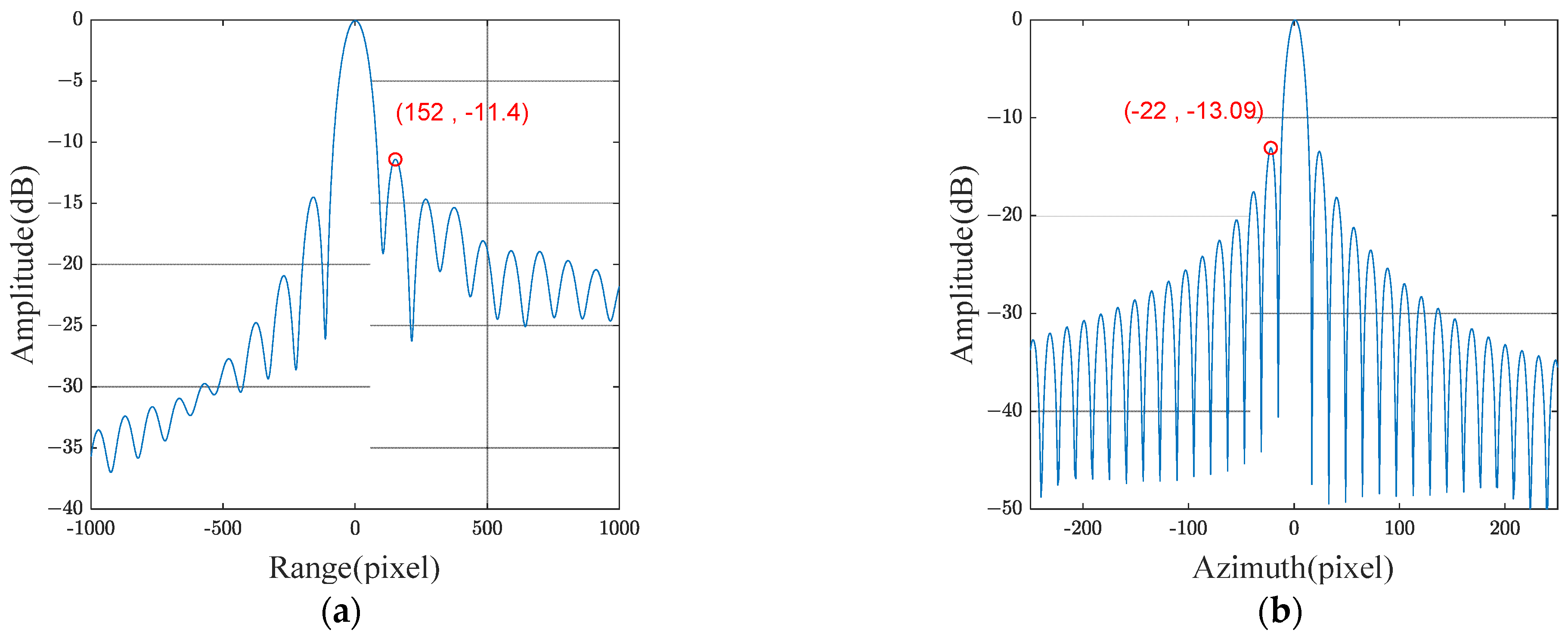
Peak side lobe ratio (PSLR) is the main parameter to evaluate the quality of pulse compression. Therefore, range and azimuth profiles are illustrated in Figure 8a,b. Figure 8 shows that the PSLR without windowing is −11.4 dB in the range and −13.09 dB in the azimuth without a window. Meanwhile, the PLSR of this wideband chirp signal is about 2 dB worse than the theoretical value in the range. However, according to engineering experience, it will not affect high-quality imaging.
Summarizing the above discussion, the design of the LFM signal generator starts with the establishment of a mathematical model for PLL. By simulating and measuring the phase-locked loop, the loop parameters are iteratively optimized, and a small frequency error and frequency nonlinearity are obtained. Finally, good pulse compression performance is achieved in both range and azimuth directions.

3.3. Active Phased Array Antennas

The proposed W-Band one-dimension phased array antenna requires angle scanning of 15° in elevation (range), and the side lobe in elevation is no more than −15 dB. This indicates that the antenna needs to have the advantages of low sidelobe and high efficiency. Meanwhile, the spacing of the W-Band antenna unit is small (only about 1.5 mm), which also brings difficulties to the integration. All these are difficult problems to be solved in this paper.
Firstly, for the W-Band millimeter wave phased array, the loss of phase-shifting devices is high, which will cause problems of insufficient operating distance and low SNR. This paper presents a new design scheme for the FMCW phased array to reduce the loss caused by multi-bit phase-shifting devices, and the scheme is shown in Figure 10. Figure 9a presents the traditional FMCW phased array design method, and Figure 9b presents the method proposed in this paper. The traditional phased array scheme utilizes phase shifters in the receiving link and the transmitting link. Our scheme includes a two-stage phase shifter. The first stage realizes a large-scale phase shift after transmitting the waveform, which is shared by all TRs; the second stage carries out a fine phase adjustment for each TR. With this new design method, each TR can avoid using a 3-bit phase shifter. In the W-Band, the loss of a one-bit phase shifter is about 2 dB [30,33]. As a result, the loss is reduced by about 6 dB, and the system efficiency is improved by about 70%.
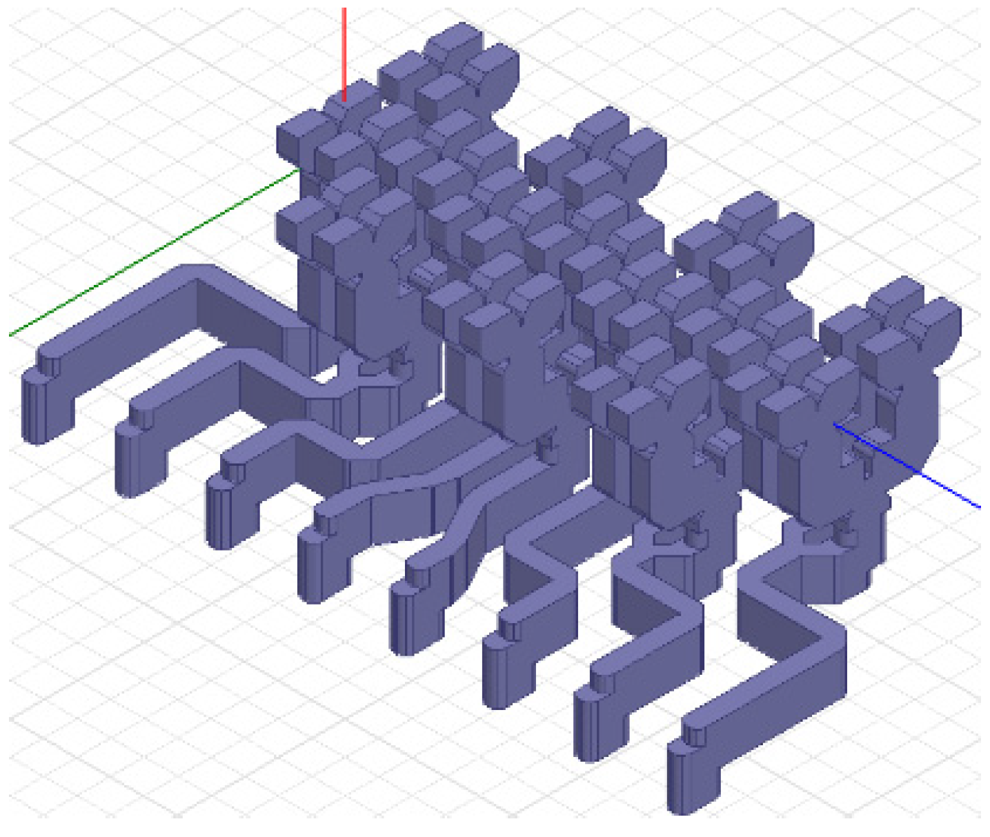
Secondly, compared with the microstrip antenna, the horn antenna has some advantages in the millimeter wave band. For example, it has good performance in impedance matching bandwidth, radiation efficiency, power capacity, and directional radiation. In this design scheme, the antennas adopt the horn antenna unit with a high gain and a low loss, and the feed adopts the form of a metal waveguide line to reduce the transmission loss. Meanwhile, the simulation model of the horn antenna unit is established, as shown in Figure 10. These measures are taken to ensure the realization of the high gain demand of the system for the antenna.
Unlike the traditional phased array design which usually adopts a rectangular arrangement, our design adopts a triangular layout, which is conducive to integration. The triangular arrangement can reduce the number of elements required by the planar array to meet the same antenna radiation performance [34,35]. Secondly, the triangular arrangement can make the units be arranged closely so that the phased array antenna can realize a lower sidelobe.
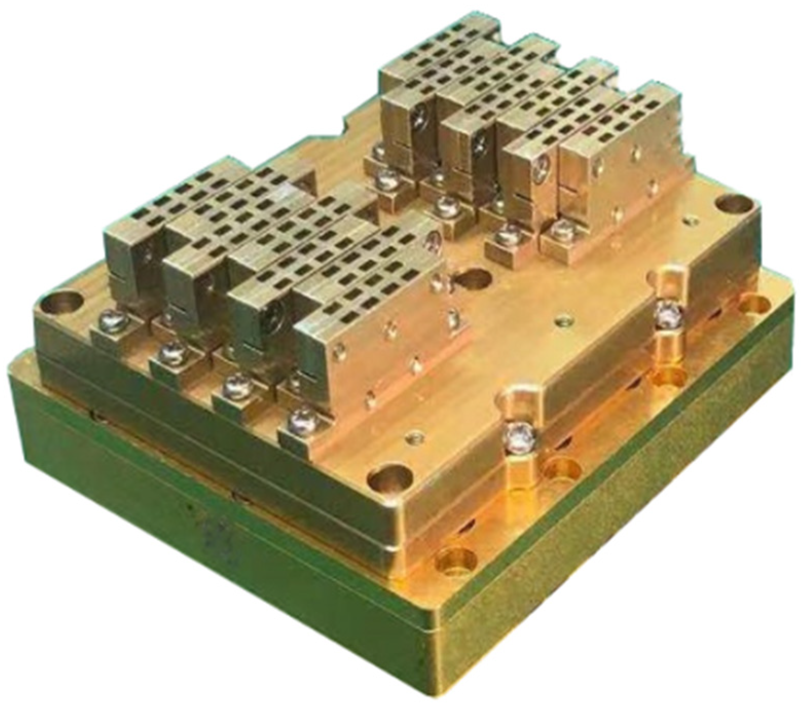
Taylor weighting is applied to amplitude weighting, and then the sidelobe is optimized by a genetic algorithm. After the simulation design and iterative optimization, the antenna is fabricated and tested. The actual antenna is shown in Figure 11, and the measured patterns in the elevation direction are shown in Figure 12. It can be observed that the antenna achieves a scanning angle of ±15 °, and the sidelobe is less than 15 dB.
In this W-Band phased array design, based on the new phased array architecture, a high-efficiency antenna design is realized by using the horn array. Meanwhile, the triangular arrangement is used to reduce the difficulty of integration, and the low sidelobe design of the antenna is realized by the sidelobe optimization method based on the genetic algorithm.

3.4. Motion Compensation Method

The W-Band APA mini-SAR works at the center frequency of 94 GHz, and the wavelength is only about 3 mm. This indicates that a small range error corresponds to a large phase change. Therefore, the W-Band mini-SAR is sensitive to platform jitters, which will result in serious trajectory deviations and residual motion errors (RMEs). Traditional methods use the high-precision IMU to measure these errors and then compensate for them. However, for the lightweight design of the whole system, a micro-electro-mechanical system inertial measurement unit (MEMS-IMU) is used, which has poor measurement accuracy. All of these pose challenges to the realization of the motion compensation algorithm, so it is necessary to optimize the traditional motion compensation methods.
In this section, a new motion compensation method is proposed based on the symmetrical triangle LFM continuous wave signal. This method was proposed by our team and has been introduced in detail in the literature [36,37]. Here, it is applied to optimize the proposed APA mini-SAR. In APA mini-SAR, triangular waves with positive and negative linear frequency modulations are employed. Based on this, the distance and speed of the target can be estimated through the beat signal between the positive and negative sweep pulses. This motion compensation method relies on this triangular wave to extract the range error and then realizes residual error estimation and removes the aperture phase error. This algorithm is divided into four steps.
Firstly, a coarse-focused SAR image is obtained by using a low-precision MEMS-IMU and the ωK imaging algorithm. Secondly, the distance and velocity can be extracted by analyzing the intermediate frequency echo of the distinguishable target. In this way, the change in the instantaneous slant range between the UAV platform and the target can be calculated. These changes are the values of RMEs. Generally, the distance migration gradient is very small in one aperture time, which is difficult to measure accurately. However, in this method, the residual error is calculated directly from the positive and negative frequency sweep pulses, thus avoiding interpolation and error accumulation. Thirdly, the residual RCM and the related phase errors are compensated based on the extracted motion errors. Fourthly, an iterative methodology is adopted to improve the stability and accuracy of motion compensation. Finally, the APE is removed from the imaging data, and a well-focused image is obtained.

4. Results Discussion

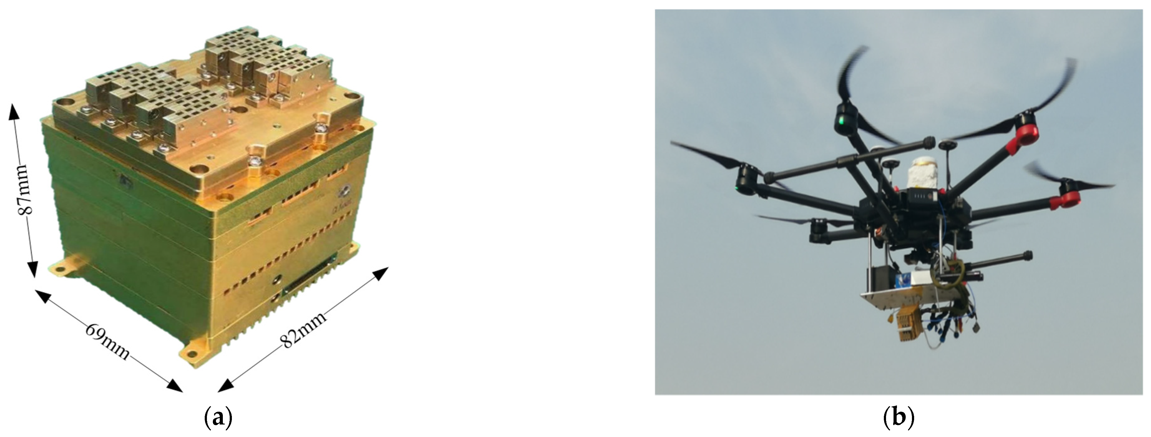
Finally, a W-Band active phased array miniaturized SAR is fabricated by using commercial chips and 3D integration technology, as shown in Figure 13a. The antennas, RF components, digital circuits, and global positioning system (GPS) are designed into a compact cube. The W-Band active phased array antenna and the beam control circuit are arranged on the top of the module. The LFM source and IF receiver are packaged in the middle layer at the bottom of the mini-SAR GPS, and digital circuits are assembled. The signal transmission between multiple layers is realized by the interconnection technology of vertical transmission lines, including transmitting signals, receiving intermediate frequency signals, control signals, power supply, etc. The prototype APA mini-SAR weighs 600 g, and its size is 69 mm × 82 mm × 87 mm, with a power consumption of 36 watts.
In Figure 13b, an imaging test is conducted on the multi-rotor UAV equipped with the proposed APA mini-SAR. In addition to the APA mini-SAR, battery, Mems-IMU, and GPS antenna are also installed on the UAV platform. During the experiment, the cruising altitude of the multi-rotor UAV is 400 m, the speed is about 15 m per second, the downward viewing angle is 30°, and the SAR is operating in a side view strip mode. After completing the planned flight route, the original SAR echo data and position information of the SAR are recorded.
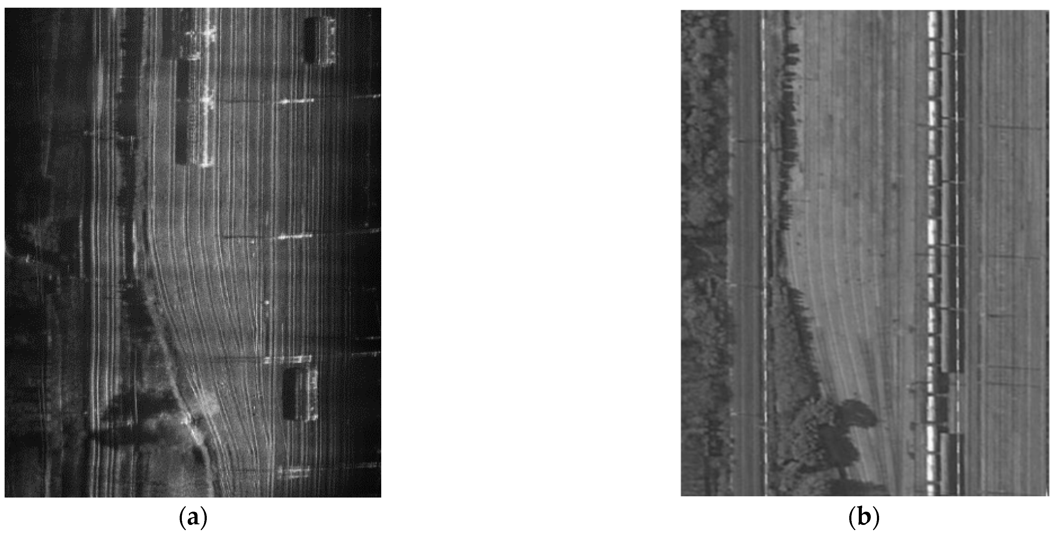
Based on the ωK algorithm and the motion compensation algorithm proposed in this paper, the SAR echo data is processed, and the SAR image with good focusing and high resolution is obtained and presented in Figure 14a. Obviously, the targets of the imaging results are easy to identify, including trains, railways, trees, and telegraph poles. Figure 14b shows the optical image of Google maps from the same area. By comparing Figure 14a,b, it can be seen that the image of the W-Band SAR has optical characteristics.
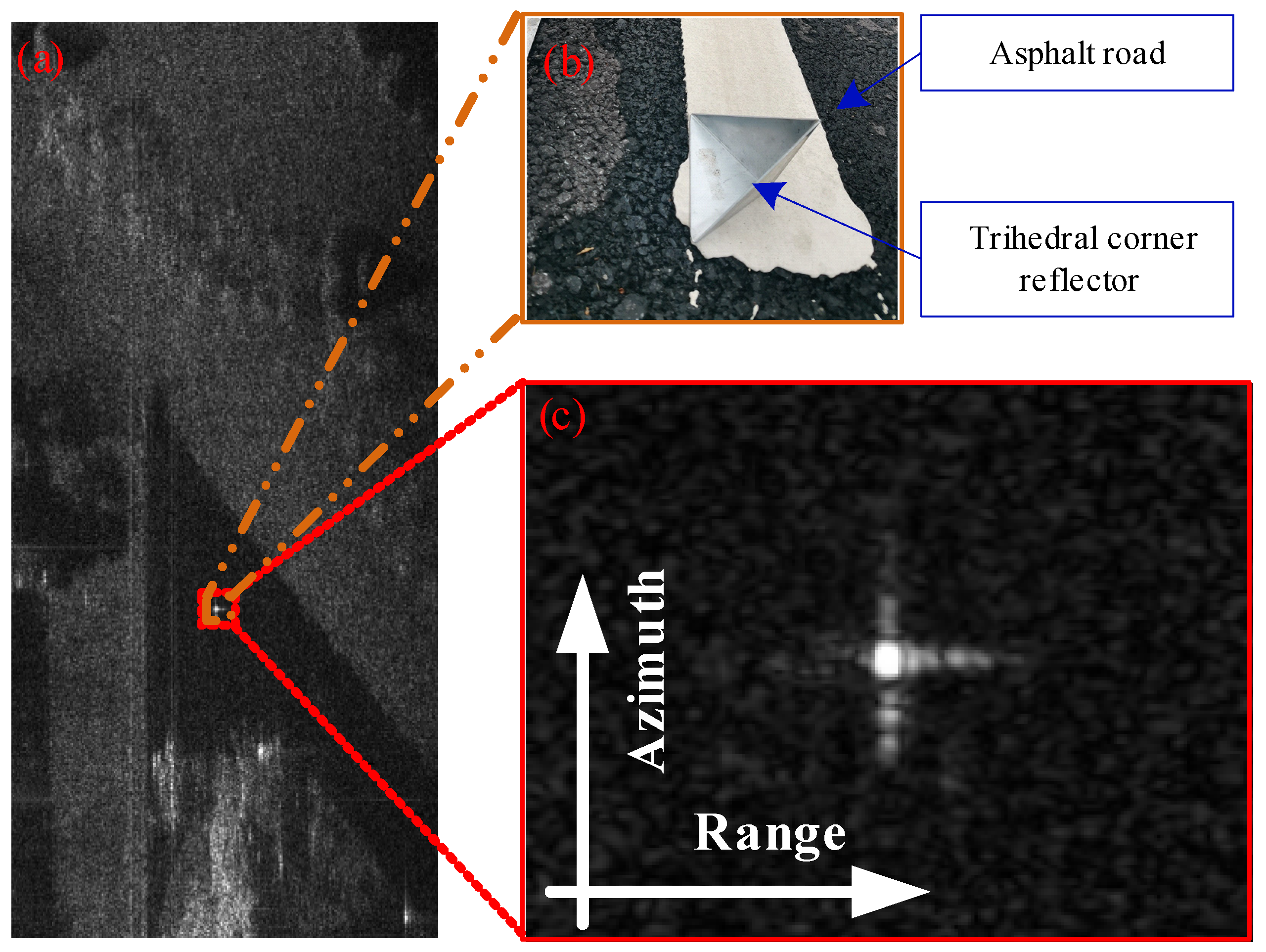
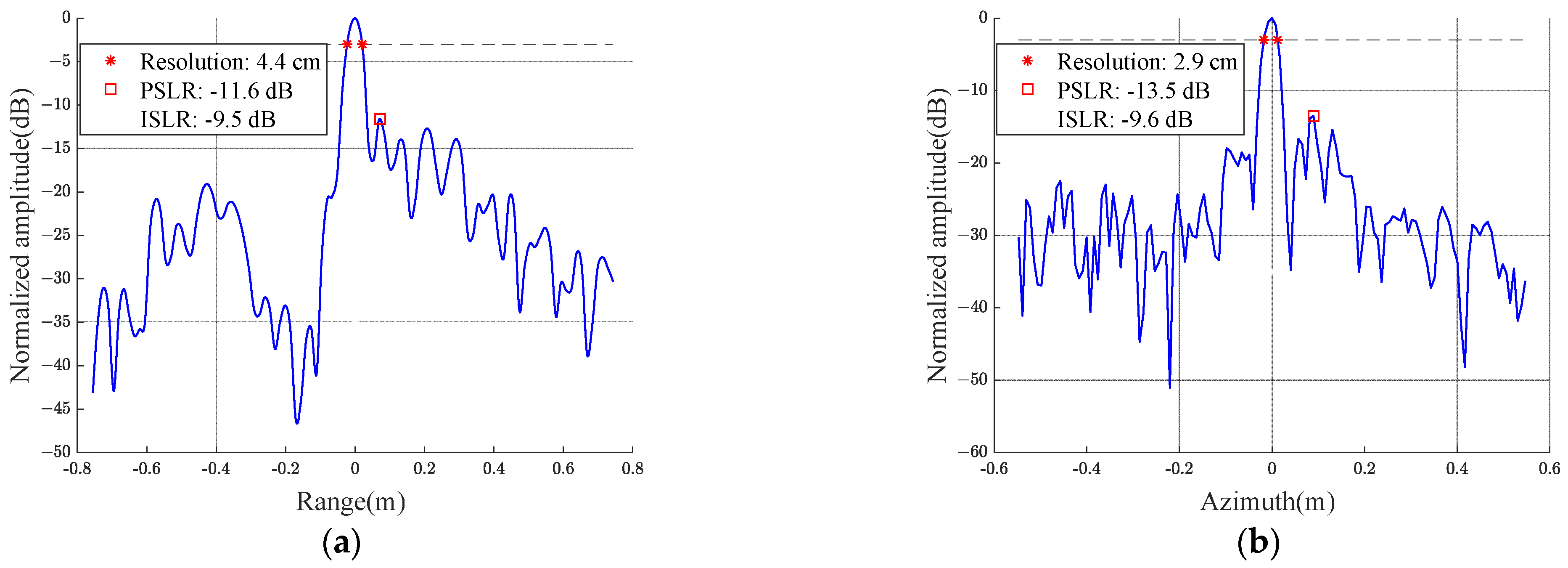
During the imaging experiment, a trihedral corner reflector is arranged in the imaging area to better evaluate the image quality. Figure 15 presents the response of the trihedral corner reflector. After the imaging processing is completed, the imaging results of the triangular reflector are analyzed in detail, and the profile in range and azimuth are illustrated in Figure 16a,b, respectively.
The measured values of the resolution, PSLR, and ISLR are listed in Table 2. It can be seen that the proposed SAR system has high resolution in range and azimuth. The ISLR of the system is slightly poor, which may be related to the waveform nonlinearity in the range and the unsatisfactory image focusing in azimuth.
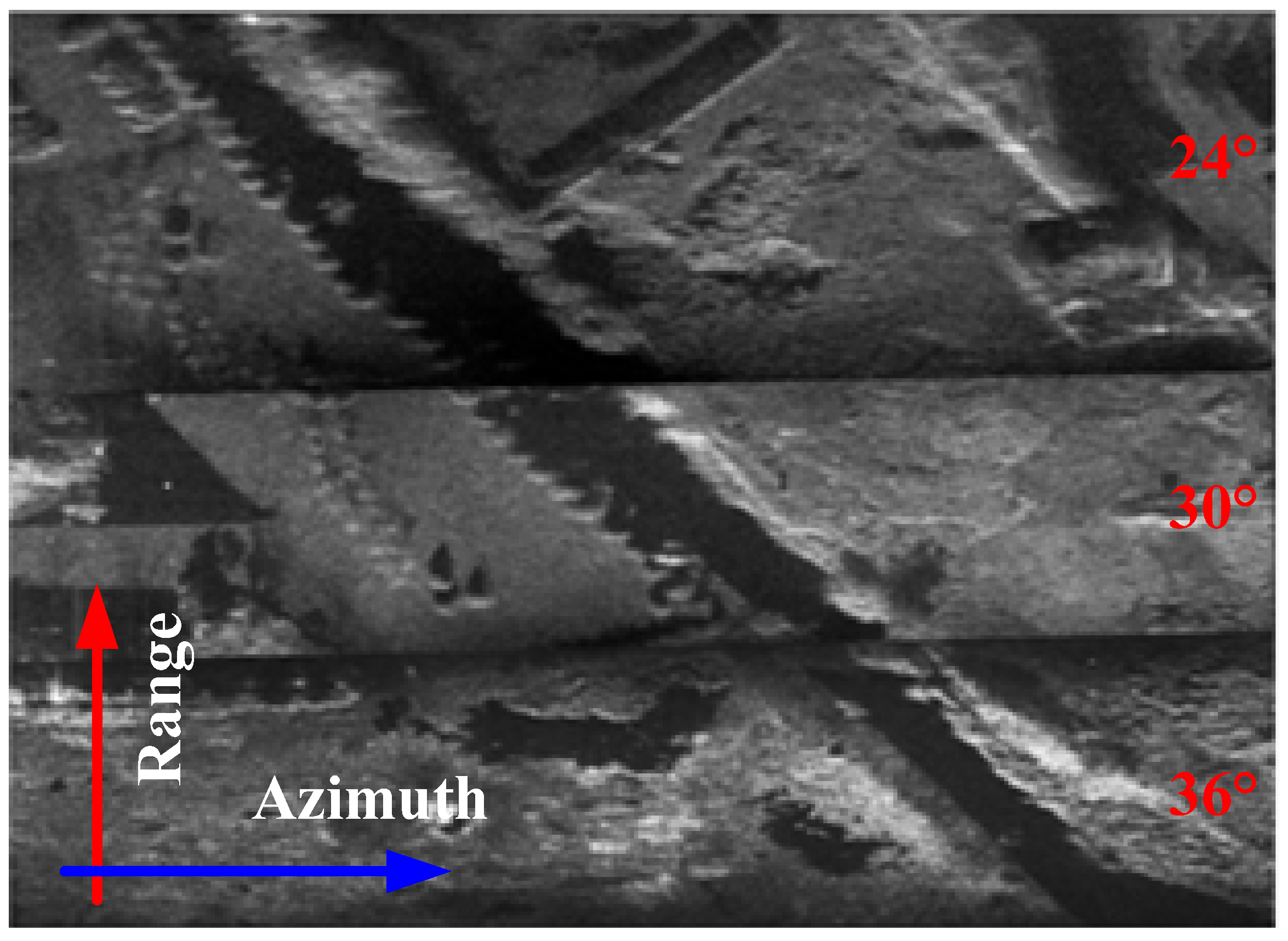
As mentioned in Section 3, the proposed SAR system has a beam scan of ±15 degrees in the elevation direction. Therefore, based on phased array antenna technology, wide-swath imaging can be achieved by repeatedly switching beam pointing between different PRFs. In this experiment, the beam pointing angle relative to the antenna’s normal direction is set to −6 degrees, 0 degrees, and 6 degrees to switch repeatedly. This SAR is installed on the multi-rotor UAV with a downward view of 30 degrees. Therefore, it is equivalent to repeatedly switching the downward viewing angle between 24 degrees, 30 degrees, and 36 degrees, thus realizing the imaging of different range strips.
The experimental results show that the imaging swath of a single beam is about 331 m. When the images of the three beams are spliced in the range direction, as shown in Figure 17, the swath is widened to about 1000 m, which effectively improves the imaging swath of the proposed SAR system.
To significantly show the performance of APA mini-SAR, the key technical specifications of typical UAV mini-SARs are compared [5,10,12,38,39,40,41], as listed in Table 3. It can be observed that this W-Band APA mini-SAR has performance advantages in imaging resolution, weight, and beam scanning ability.

5. Conclusions

In this paper, a W-Band active phased array miniaturized SAR system has been validated on a multi-rotor UAV, and the results show that this SAR with high imaging resolution and wide swath imaging using phased array technology is feasible within a very compact design. Meanwhile, a series of methods have been used to achieve this advanced APA mini-SAR, such as a wideband chirp generator, a novel active phased array antenna scheme for the W-Band FMCW radar, a new motion compensation strategy based on symmetrical triangle LFM continuous wave signals, and the 3D integration method.
Finally, the APA mini-SAR with a weight of about 600 g and a volume of about 69 mm × 82 mm × 87 mm has been fully tested. By splicing in the range direction, the proposed APA mini-SAR has an imaging resolution of better than 4.4 cm and a swath of 1000 m.
Through the comparison with existing literature, in the W-Band, the APA Mini-SAR has performance advantages in weight, volume, power consumption, high resolution, and wide swath.
In the future, real-time imaging and SAR microsystems based on microelectronic technology will be the focus of research, and the design of compact signal processors and system-integrated chips will be investigated.

Author Contributions

All the authors made contributions to the article in different areas. Conceptualization, M.D., X.W. and L.Z.; investigation, M.D. and L.T.; simulation, M.D., Y.W. and B.W.; writing—original draft preparation, M.D. and X.W.; writing—review and editing, M.D., L.T., J.Q., Y.W. and X.W. All authors have read and agreed to the published version of the manuscript.

Funding

This research was funded by the National Key Basic Research Program of China (Grant No. 2019YFA0210204).

Data Availability Statement

Data sharing not applicable.

Acknowledgments

The authors thank all colleagues who participated in the APA mini-SAR system. We also thank the staff for their help in the imaging experiment.

Conflicts of Interest

The authors declare no conflict of interest.

References

  1. Rosen, P.A.; Hensley, S.; Wheeler, K.; Sadowy, G.; Miller, T.; Shaffer, S.; Muellerschoen, R.; Jone, C.; Zebker, H.; Madsen, S. UAVSAR: A new NASA airborne SAR system for science and technology research. In Proceedings of the 2006 IEEE Conference on Radar, Verona, NY, USA, 24–27 April 2006. [Google Scholar] [CrossRef] [Green Version]
  2. Zhang, X.; Shao, Z.; Ren, J.; Li, Y.; Jiang, J. Development and preliminary results of small-size UAV-borne FMCW SAR. In Proceedings of the 2018 IEEE International Geoscience and Remote Sensing Symposium (IGARSS), Valencia, Spain, 23–27 July 2011. [Google Scholar] [CrossRef]
  3. Yan, J.; Guo, J.; Lu, Q.; Wang, K.; Liu, X. X-band mini SAR radar on eight-rotor mini-UAV. In Proceedings of the 2016 IEEE International Geoscience and Remote Sensing Symposium (IGARSS), Beijing, China, 10–15 July 2011. [Google Scholar] [CrossRef]
  4. Wang, Y.; Liu, C.; Zhan, X.; Han, S. Technology and applications of UAV synthetic aperture radar system. J. Electron. Inf. Technol. 2016, 5, 333–349. [Google Scholar] [CrossRef]
  5. Lort, M.; Aguasca, A.; López-Martínez, C.T.; Marín, M. Initial evaluation of SAR capabilities in UAV multicopter platforms. IEEE J. Sel. Top. Appl. Earth Obs. Remote Sens. 2018, 11, 127–140. [Google Scholar] [CrossRef] [Green Version]
  6. Evearerts, J. The use of Unmanned Aerial Vehicles (UAVs) for remote sensing and mapping. Int. Arch. Photogramm. Remote Sens. Spat. Inf. Sci. 2008, 37, 1187–1192. [Google Scholar]
  7. Li, W.; Chen, X.; Li, G.; Bi, Y. Construction of Yunnan’s agricultural ecological civilization based on intelligent UAV and SAR image analysis. In Proceedings of the 2022 4th International Conference on Smart Systems and Inventive Technology (ICSSIT), Tirunelveli, India, 20–22 January 2022. [Google Scholar] [CrossRef]
  8. Dill, S.; Schreiber, E.; Engel, M.; Heinzel, A.; Peichl, M. A drone carried multichannel Synthetic Aperture Radar for advanced buried object detection. In Proceedings of the 2019 IEEE Radar Conference (RadarConf), Boston, MA, USA, 22–26 April 2019. [Google Scholar] [CrossRef]
  9. Caris, M.; Stanko, S.; Palm, S.; Sommer, R.; Pohl, N. Synthetic aperture radar at millimeter wavelength for UAV surveillance applications. In Proceedings of the 2015 IEEE 1st International Forum on Research and Technologies for Society and Industry Leveraging a better tomorrow (RTSI), Turin, Italy, 16–18 September 2015. [Google Scholar] [CrossRef]
  10. Ding, M.; Ding, C.; Tang, L.; Wang, X.; Qu, J.; Wu, R. A W-band 3-D integrated mini-SAR system with high imaging resolution on UAV platform. IEEE Access 2020, 8, 113601–113609. [Google Scholar] [CrossRef]
  11. Bekar, A.; Antoniou, M.; Baker, J.C. Low-cost, high-resolution, drone-borne SAR imaging. IEEE Trans. Geosci. Remote Sens. 2022, 60, 1–11. [Google Scholar] [CrossRef]
  12. Edrich, M.; Weiss, G. Second-generation Ka-Band UAV SAR system. In Proceedings of the 2008 European Radar Conference, Amsterdam, The Netherlands, 27–31 October 2008. [Google Scholar] [CrossRef]
  13. Edrich, M. Design overview and flight test results of the miniaturised SAR sensor MISAR. In Proceedings of the 2004 First European Radar Conference, Amsterdam, The Netherlands, 11–15 October 2004. [Google Scholar]
  14. Wang, R.; Deng, Y.; Wang, P. Recent progress of airborne X-band SAR with two-dimensional digital beamforming. In Proceedings of the EUSAR 2016: 11th European Conference on Synthetic Aperture Radar, Hamburg, Germany, 5 September 2016. [Google Scholar]
  15. Nan, Y.; Huang, X.; Guo, Y. Generalized continuous wave synthetic aperture radar for high resolution and wide swath remote sensing. IEEE Trans. Geosci. Remote Sens. 2018, 56, 7217–7229. [Google Scholar] [CrossRef]
  16. Hees, A.; Stangl, M.; Adamiuk, G.; Riegger, S.; Heer, C. Status and future trends of active phased array antennas for AIRBUS space-borne SAR systems. In Proceedings of the 2019 IEEE International Symposium on Phased Array System & Technology (PAST), Waltham, MA, USA, 15–18 October 2019. [Google Scholar] [CrossRef]
  17. Zhou, Y.; Wang, W.; Chen, Z.; Zhao, Q.; Zhang, H.; Deng, Y.; Wang, R. High-resolution and wide-swath SAR imaging mode using frequency diverse planar array. IEEE Geosci. Remote Sens. Lett. 2021, 18, 321–325. [Google Scholar] [CrossRef]
  18. Krieger, G.; Gebert, N.; Younis, M.; Moreira, A. Advanced synthetic aperture radar based on digital beamforming and waveform diversity. In Proceedings of the 2008 IEEE Radar Conference, Rome, Italy, 26–30 May 2008. [Google Scholar] [CrossRef] [Green Version]
  19. AlShaya, M.; Yaghoobi, M.; Mulgrew, B. Ultrahigh resolution wide swath MIMO-SAR. IEEE J. Sel. Top. Appl. Earth Obs. Remote Sens. 2020, 13, 5358–5368. [Google Scholar] [CrossRef]
  20. Zhang, X.; Yang, C.; Zhang, X.; Lin, Q. Multi-channel SAR system design for HRWS and GMTI in low PRF. IEEE Access 2020, 8, 40939–40954. [Google Scholar] [CrossRef]
  21. Hees, A.; Stangl, M.; Schwämmlein, T.; Rathke, A. X-band phased array antenna frontends for next generation SAR instruments. In Proceedings of the 2019 IEEE International Symposium on Phased Array System & Technology (PAST), Waltham, MA, USA, 15–18 October 2019. [Google Scholar] [CrossRef]
  22. Buckreuss, S.; Balzer, W.; Mühlbauer, P.; Werninghaus, R.; Pitz, W. The terraSAR-X satellite project. In Proceedings of the 2003 IEEE International Geoscience and Remote Sensing Symposium, Toulouse, France, 21–25 July 2003. [Google Scholar] [CrossRef]
  23. Herd, J.S.; Conway, M.D. The evolution to modern phased array architectures. Proc. IEEE 2016, 104, 519–529. [Google Scholar] [CrossRef]
  24. Brautigam, B.; Schwerdt, M.; Bachmann, M. An efficient method for performance monitoring of active phased array antennas. IEEE Trans. Geosci. Remote Sens. 2009, 47, 1236–1243. [Google Scholar] [CrossRef] [Green Version]
  25. Jankiraman, M. FMCW Radar Design; Artech House: London, UK, 2018. [Google Scholar]
  26. Möhring, B.; Moroder, C.; Siart, U.; Eibert, T. Broadband, Fast, and Linear Chirp Generation Based on DDS for FMCW Radar Applications. In Proceedings of the 2019 IEEE Radar Conference, Boston, MA, USA, 22–26 April 2019. [Google Scholar] [CrossRef]
  27. Rubio-Cidre, G.; Badolato, A.; Úbeda-Medina, L.; Grajal, J.; Mencia-Oliva, B.; Dorta-Naranjo, B. DDS-Based Signal-Generation Architecture Comparison for an Imaging Radar at 300 GHz. IEEE Trans. Instrum. Meas. 2015, 64, 3085–3098. [Google Scholar] [CrossRef]
  28. Afroz, S.; Koh, K.J. 90° hybrid-coupler based phase-interpolation phase-shifter for phased-array applications at W-band and beyond. In Proceedings of the 2016 IEEE MTT-S International Microwave Symposium (IMS), San Francisco, CA, USA, 22–27 May 2016. [Google Scholar] [CrossRef] [Green Version]
  29. Lee, H.; Min, B. W-band CMOS 4-bit phase shifter for high power and phase compression points. IEEE Trans. Circuits Syst. II Express Briefs 2015, 62, 1–5. [Google Scholar] [CrossRef]
  30. Zhao, Z. New progress of the micro system three-dimensional integration technology. Micronanoelectron. Technol. 2017, 54, 1–10. (In Chinese) [Google Scholar]
  31. Li, Y.; Goyal, D. 3D Microelectronic Packaging: From Fundamentals to Applications; Springer Publishing Company: Berlin, Germany, 2017. [Google Scholar]
  32. Hao, J.; Xiang, W. 3D Heterogeneous integration for micro-system and its application. Electron. Process Tech. 2018, 39, 317–321. [Google Scholar]
  33. Romano, A.; Sonnenberg, T.; Verploegh, S.; Barton, T.; Popovic, Z. A W-Band GaN MMIC Continuous 90° Reflective Phase Shifter. In Proceedings of the 2022 IEEE 22nd Annual Wireless and Microwave Technology Conference, Clearwater Beach, FL, USA, 27–28 April 2022. [Google Scholar] [CrossRef]
  34. Sharp, E. A triangular arrangement of planar-array elements that reduces the number needed. IRE Trans. Antennas Propag. 1961, 9, 126–129. [Google Scholar] [CrossRef]
  35. Xing, W.; Qu, S.; Yang, S. A Wideband Phased Antenna Array Based on Tapered Cavities in Triangular Lattice Arrangement. In Proceedings of the 2018 IEEE International Conference on Computational Electromagnetics, Chengdu, China, 13–15 April 2018. [Google Scholar] [CrossRef]
  36. Xu, W.; Wang, B.; Xiang, M.; Wang, S.; Yin, J. A novel motion compensation approach based on symmetric triangle wave interferometry for UAV SAR imagery. IEEE Access 2020, 8, 104996–105007. [Google Scholar] [CrossRef]
  37. Xu, W.; Wang, B.; Xiang, M.; Song, C.; Wang, Z. A novel autofocus framework for UAV SAR imagery: Motion error extraction from symmetric triangular FMCW differential signal. IEEE Trans. Geosci. Remote Sens. 2022, 60, 1–15. [Google Scholar] [CrossRef]
  38. Zaugg, E.; Edwards, M.; Long, D.; Stringham, C. Developments in compact high-performance synthetic aperture radar systems for use on small Unmanned Aircraft. In Proceedings of the 2011 Aerospace Conference, Big Sky, MT, USA, 5–12 March 2011. [Google Scholar] [CrossRef]
  39. van der Graaf, M.W.; Otten, M.P.G.; Huizing, A.G.; Tan, R.G.; Cuenca, M.C.; Ruizenaar, M.G.A. AMBER: An X-band FMCW digital beam forming synthetic aperture radar for a tactical UAV. In Proceedings of the 2013 IEEE International Symposium on Phased Array Systems and Technology, Waltham, MA, USA, 15–18 October 2013; pp. 165–170. [Google Scholar]
  40. Essen, H.; Bräutigam, M.; Sommer, R.; Wahlen, A.; Johannes, W.; Wilcke, J.; Schlechtweg, M.; Tessmann, A. SUMATRA, a W-band SAR for UAV application. In Proceedings of the 2009 International Radar Conference, Bordeaux, France, 12–16 October 2019. [Google Scholar]
  41. Essen, H.; Johannes, W.; Stanko, S.; Sommer, R.; Wahlen, A.; Wilcke, J. High resolution W-band UAV SAR. In Proceedings of the 2012 IEEE International Geoscience and Remote Sensing Symposium, Munich, Germany, 22–27 July 2012. [Google Scholar] [CrossRef]
Figure 1. The schematic of the proposed W-Band APA mini-SAR system.
Remotesensing 14 05840 g001
Figure 2. Simulation results of NESZ.
Remotesensing 14 05840 g002
Figure 3. The diagram of the integrated phased array mini-SAR.
Remotesensing 14 05840 g003
Figure 4. Simulation results of frequency and frequency error with time.
Remotesensing 14 05840 g004
Figure 5. Test results of phase stability between pulses with time.
Remotesensing 14 05840 g005
Figure 6. Frequency error analysis. (a) Frequency error of the LFM signals. (b) Frequency linearity of the mini-SAR.
Remotesensing 14 05840 g006
Figure 7. The imaging results of the point target.
Remotesensing 14 05840 g007
Figure 8. Results of range profile and azimuth profile. (a) Range profile. (b) Azimuth profile.
Remotesensing 14 05840 g008
Figure 9. The W-Band active phased array antenna for the FMCW radar. (a) traditional scheme. (b) new scheme.
Remotesensing 14 05840 g009
Figure 10. The simulation model of the one-dimensional phased array based on a triangular arrangement.
Remotesensing 14 05840 g010
Figure 11. The W-Band active phased array antenna.
Remotesensing 14 05840 g011
Figure 12. The measured patterns in the elevation direction.
Remotesensing 14 05840 g012
Figure 13. The W-Band APA mini-SAR and the photography on UAV. (a) The prototype of the W-Band APA mini-SAR. (b) The W-Band APA mini-SAR on the UAV platform.
Remotesensing 14 05840 g013
Figure 14. Comparison between APA mini-SAR image and the optical image. (a) W-Band active phased array miniaturized SAR image. (b) The optical image from Google Maps.
Remotesensing 14 05840 g014
Figure 15. The SAR image with a trihedral reflector. (a) SAR image. (b) The optical image of the trihedral reflector. (c) The zoom-in image of the trihedral reflector.
Remotesensing 14 05840 g015
Figure 16. The profile of the trihedral reflector. (a) In range. (b) In azimuth.
Remotesensing 14 05840 g016
Figure 17. Image splicing in the range direction.
Remotesensing 14 05840 g017
Table 1. Key parameters of the W-Band APA mini-SAR.
ParameterValue
Center frequency95 GHz
Signal bandwidth4000 MHz
WaveformLFM
Max imaging range1000 m
Downward look angle30°
Scanning angle±15°
Antenna beams>100 elevation beams
Slant range resolution3.75 cm
Azimuth resolution2.5 cm
Weight0.6 kg
Volume69 × 82 × 87 mm3
Table 2. Image quality assessment.
Items Measured Values
Resolution (cm)Rang4.4
Azimuth2.9
PSLR (dB)Rang−11.6
Azimuth−13.5
ISLR (dB)Rang−9.5
Azimuth−9.6
Table 3. Key technical specifications of typical UAV mini-SAR.
Ref.Beam ScanningBandRes.Weight
[38]NoC0.75 m2.5 kg
[5]NoX1.5 m2 kg
[39]YesX0.1 m6 kg
[12]NoKa0.5 m4 kg
[40,41]NoW0.15 m~2.2 kg
[10]NoW0.045 m0.4 kg
This workYesW0.045 m0.6 kg
Publisher’s Note: MDPI stays neutral with regard to jurisdictional claims in published maps and institutional affiliations.