Article

A Morphing-Based Method for Paleotopographic Reconstruction of the Transverse Canyon

1
Key Laboratory of Virtual Geographic Environment (Nanjing Normal University), Ministry of Education, Nanjing 210023, China
2
Jiangsu Center for Collaborative Innovation in Geographical Information Resource Development and Application, Nanjing 210023, China
3
State Key Laboratory Cultivation Base of Geographical Environment Evolution (Jiangsu Province), Nanjing Normal University, Nanjing 210023, China
4
State Key Laboratory of Soil and Sustainable Agriculture, Institute of Soil Science, Chinese Academy of Sciences, Nanjing 210008, China
*
Author to whom correspondence should be addressed.
Remote Sens. 2022, 14(23), 6109; https://doi.org/10.3390/rs14236109
Submission received: 12 October 2022 / Revised: 23 November 2022 / Accepted: 30 November 2022 / Published: 2 December 2022

Abstract

:
The transverse canyon is a V-shaped, fluvial-genetic canyon, a secondary valley formed by transverse drainage crossing a tectonically uplifted mountain. Paleotopography of the transverse canyon is vital to drainage connection and river capture, offering insight into the processes that link large-scale river systems, analyzing paleodrainage patterns, and recreating headward erosion. Notably, modern paleotopographic reconstruction methods are usually limited to reconstructions of paleotopography in vast sedimentary basins and denuded hills in orogenic belts. When applied to transverse canyons, a specific secondary valley found in tiny locations, these techniques are difficult, expensive, and ineffective. This paper proposes an automated method for reconstructing the paleotopography of the transverse canyon using the digital elevation model (DEM) and river. (1) Restore the ridgeline above the transverse canyon based on the ridgelines of the mountains on both sides; (2) create a buffer zone based on the river centerline with unequal buffer distances on each side; (3) construct a mesh surface by interpolating transition curves from the morphing method, using the three-edge type; (4) apply a spatial interpolation method to the elevation points on the mesh surface to construct the DEM above the transverse canyon and stitch it to the input DEM to obtain the paleotopographic DEM; (5) calculate the spatial attributes. The objective of this study is to reconstruct the paleotopography of eight typical transverse canyons in the comb-like fold belt of northern Chongqing. As part of the paleotopographic reconstruction of the transverse canyon, we address the effects of dislocated mountains, erosion gullies, and different morphing techniques, as well as the applicability of the proposed method to reconstructing other secondary valleys. In conclusion, we reconstruct paleotopographic DEMs of transverse canyons to replicate headward erosion processes, assess paleodrainage patterns, and build three-dimensional solid models.

1. Introduction

A canyon is a narrow, steep-sided valley [1]. The word “gorge” is sometimes used interchangeably with “canyon”, however, a gorge is usually invariably more narrow and steep than a canyon. According to various viewpoints, canyons are classified in several ways. The canyon’s cross-sectional morphology may be categorized as V-shaped [2] or box-shaped [3]. Canyons may be classified according to their formation circumstances as fluvial canyons [3,4,5,6], weathering erosion canyons [6,7,8,9], tectonic activity canyons [10,11,12], and mixed formation canyons [6,7]. The transverse canyon [13,14,15,16] is a V-shaped, fluvial-genetic canyon generated by transverse drainage [17,18,19] through an elevated mountain. Frequently, transverse canyons are impacted by a mixture of geographical factors, including river capture [7,20,21], river incision [10,22], headward erosion [3,9], and tectonic uplift [7,23,24]. As a crucial location for drainage connectivity [20,21], the evolution of the transverse canyon topography has become a fundamental foundation for investigating the connection mechanisms of the large-scale river system [19,25,26,27], deducing paleodrainage patterns [28,29], and reconstructing headward erosion processes [30,31,32]. Moreover, the transverse canyon is a region with a high incidence of landslides and mudslides, owing to its steep slopes and substantial river drop. Consequently, it is considered a crucial study object in water resource exploitation [33,34] and geohazard monitoring [35,36].
As one of the essential components of paleotopographic reconstruction and paleogeographic reconstruction studies, the paleotopographic reconstruction of the transverse canyon is significant for research in a number of ways, such as dynamically simulating the water system penetration process, extracting the paleodrainage spatial distribution pattern, inferring the movement process of the ancient river system [20], and reconstructing the headward process [3,9]. At present, the geological analysis method and the low-temperature thermochronological method are the two most used techniques for reconstructing paleotopography. Geological analysis techniques attempt to recreate the paleotopography of sedimentary basins by determining the base-level surfaces of various eras based on comprehensive research, such as paleostructure, paleodrainage systems, paleocurrent direction, and sedimentary facies. The residual thickness method and the moulage method [37,38,39], the backstripping technique [40] and the filling method [41], the sedimentary paleogeomorphic reconstruction method [42,43], the high-resolution sequence stratigraphy method (HRSS) [44,45], and the double-interface reconstruction method [46] are the most prevalent reconstruction techniques. The low-temperature thermochronological method calculates the denudation rate and thickness of orogenic terrain using fission tracking and (U-Th)/He dating in apatite and zircon [47,48,49,50] and generates a series of multi-layered DEMs employing spatial interpolation techniques to reconstruct paleotopography. The geological analysis techniques mostly apply to sedimentary basins and need a considerable quantity of geological data, such as those on boreholes, seismic, and cores, to enable the qualitative and quantitative reconstruction of the paleotopography. The low-temperature thermochronological method is primarily concerned with recreating paleotopography in orogenic zones generated by tectonic uplift and requires bedrock and other data. However, the transverse canyon is a denudation-type secondary valley generated by local river erosion of the mountain, which, on the one hand, is modest in size and not at all comparable to the previously stated sedimentary basins and the orogenic belt and, on the other hand, lacks data support. None of the foregoing methods can be used to recreate the paleotopography of the transverse canyon. In conclusion, this study focuses on accurately and quickly recreating the paleotopography of the transverse canyon using widely available data.
Paleotopographic reconstruction is predicated on identifying the current datum (the erosion surface) and the ancient datum of the landscape. The topographical surface of the mountains generated after the transverse canyon passes the bedrock mountains on both sides is generally intact, and the canyon’s border is clear. In antiquity, the mountains on both sides of the canyon were continuous, and the terrain undulation was comparable; therefore, the old terrain surface above the canyon may be used as an ancient datum. The current datum of the transverse canyon is the river level inside the canyon, the valley, or the plain surface on both sides of the bedrock mountain. Based on the aforementioned two datum determination concepts, this study provides a morphing-based automated reconstruction method for transverse canyon paleotopography. This method uses DEM and vector rivers as data sources to rebuild 3D paleotopography and recover the ancient datum of a transverse canyon based on several topographic feature lines. Specifically, this work is structured as follows: Section 2 analyzes the transverse canyon, Section 3 describes the study region and input data, Section 4 describes the methodology, Section 5 describes the experimental findings, Section 6 describes the discussion and applications, and Section 7 describes the conclusions.

2. Analysis of the Transverse Canyon

The development mechanism, spatial characteristics, and location of the transverse canyon are the main factors affecting the paleotopographic reconstruction. This study will discuss the above factors based on the published literature below. Then, according to the summarized characteristics, we will design the paleotopographic reconstruction method to ensure the rationality and accuracy of the reconstructed results.

2.1. Characteristics of the Transverse Canyon

Maw [13], Hopkins [15], and Thornbury [16] proposed the transverse valley, transverse gorge, and transverse river gorge ideas and provided a short description and explanation for each. Nowadays, the word “transverse canyon” is used to express various types [14,28]. The primary factor in the creation of transverse canyons [16,17,18,19] is transverse drainage. Antecedence, superimposition, overflow, and piracy or capture have been shown to be the origins of transverse drainage in prior academic investigations [28,51,52,53] either individually [51] or in combination [28,52,53]. Thornbury [16] and Douglass et al. [19] provided diagrammatic explanations of these four factors leading to the creation of transverse canyons (Figure 1).
On the basis of multiple prior studies, we outline four essential properties of the transverse canyon. These qualities include:
  • Even without a level floor, the canyon slope is steep, and the canyon bottom is narrow. Due to intense erosion, the majority of transverse canyons are V-shaped, but a handful are U-shaped.
  • The mountains spanned by transverse canyons are mostly long or spindle-shaped, and they are the consequence of tectonic uplifts, such as anticline mountains or fault-block mountains with distinct mountain ranges.
  • The extension directions of transverse canyons are orthogonal to the mountain strike, or nearly orthogonal.
  • Transverse canyons are generated primarily by river capture and headward erosion.

2.2. Locations of the Transverse Canyon

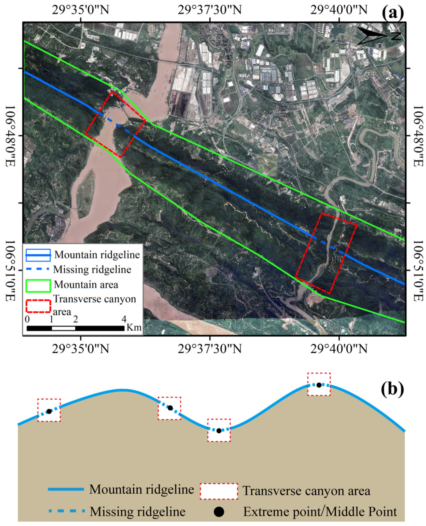
The number and location of the transverse canyons in a long bedrock mountain range are variable. For example, there are two transverse canyons in a mountain range in Chongqing, China (Figure 2a). In addition, the general tendency of the ridgeline on the long bedrock mountain is bent, and the missing ridgeline is found in various portions of the mountain, exhibiting varied patterns. We have summarized four types by analyzing all possible transverse canyon locations, shown in Figure 2b. The subsequently designed paleotopographic reconstruction algorithm will comprehensively consider the above four possibilities to ensure the rationality of restoration results.

3. Study Region and Input Data

3.1. Study Region

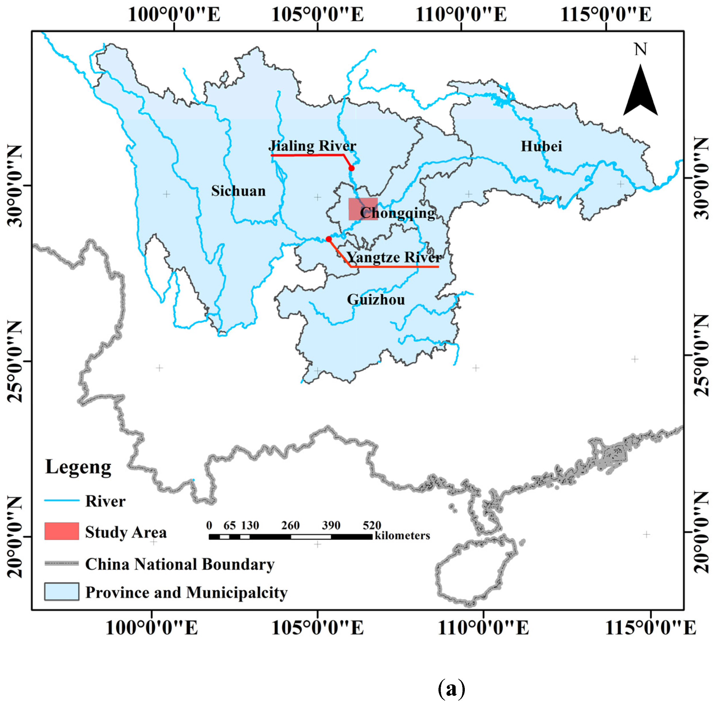
The study region is situated in the northwestern portion of Chongqing in China, between 106°00′E and 107°00′E, 29°20′N and 29°58′N (Figure 3a), inside the Sichuan fold belt. Since the Cretaceous period, Yanshan and Xishan tectonics have influenced the formation of a series of comb-like folds. There is a striking difference in the region’s landforms, with anticlines forming mountains and synclines forming valleys. The narrow and linear distribution of the anticlines and the broad, gentle, and flat distribution of the synclines combine to produce the renowned parallel ridge valley of East Sichuan.
The region under study is part of the Yangtze River Basin. As the backbone rivers of the region, the Yangtze River and Jialing River enter the structural area from the western and western sides, converge around Chaotianmen in Chongqing, and flow east out of the region. The two rivers are separated by several strip-shaped, broad, mild synclines and tight anticlines. When a river flows through a narrow anticline, the slope becomes slender and steep, and the water becomes turbulent, generating transverse canyon landforms such as Wenquan canyon, Guanyin canyon, and Tongluo canyon.
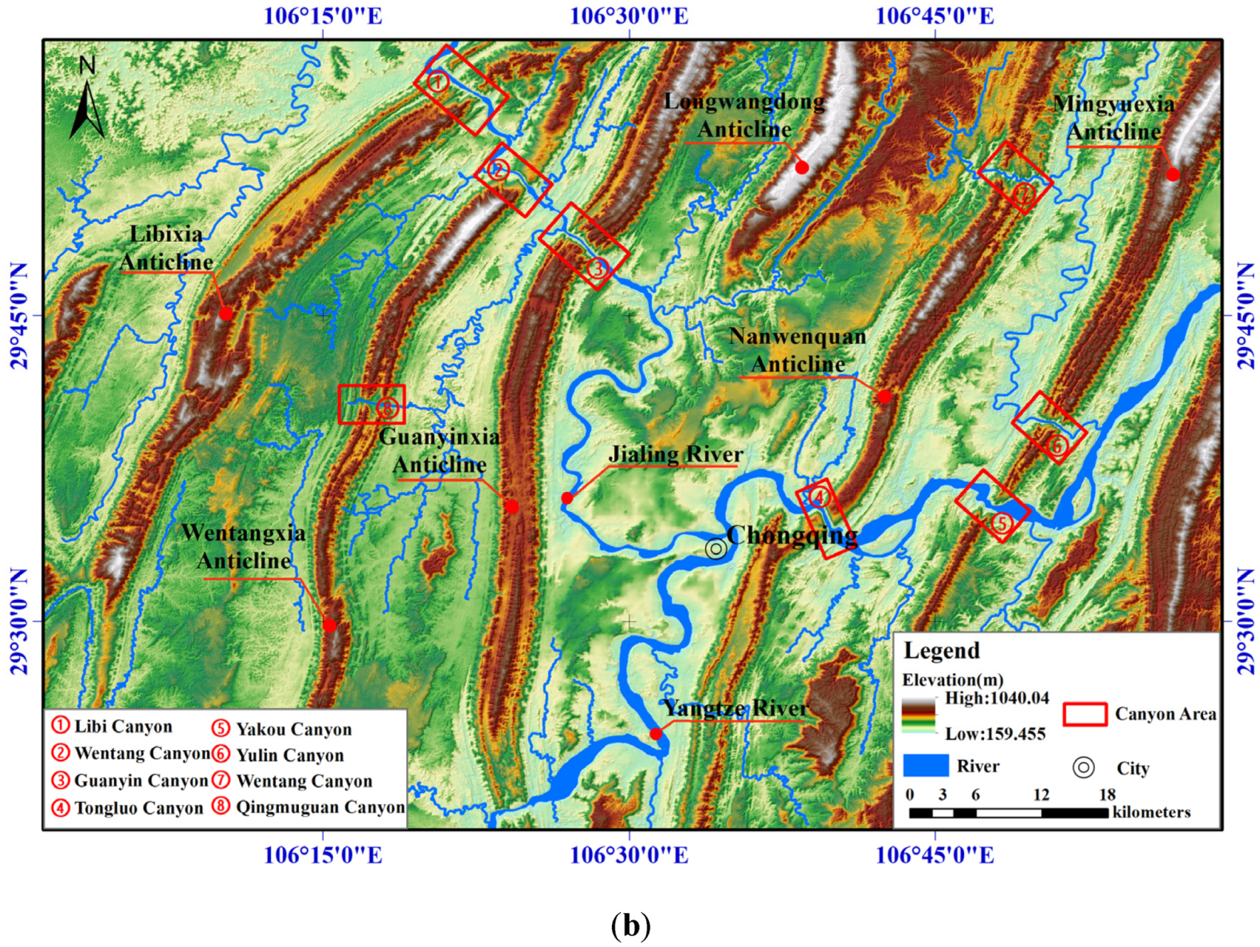
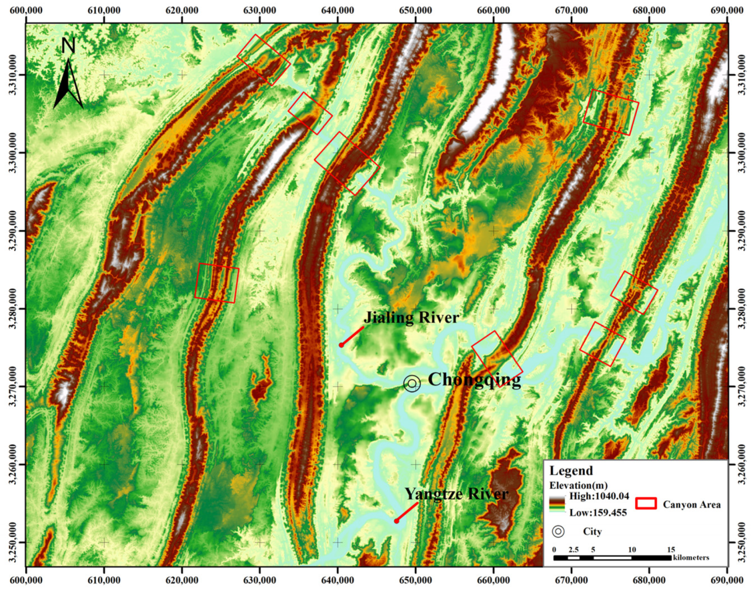
The majority of the research [25,26] indicates that the eastern Sichuan fold belt was developed before the ancient Yangtze River. The tectonic uplift in eastern Sichuan separates the middle and lower Yangtze River drainage from the higher drainage [54], and when headward erosion occurs, the upper drainage traverses the whole barrier tectonic zone to join the middle drainage [27,32]. The creation of transverse canyons in the region is primarily controlled by two kinds of transverse drainage processes, overflow and piracy [29], and the region is a prime location for the research of transverse canyon restoration. There are eight transverse canyons in the region (Figure 3b), which were eroded to varying degrees and shaped differently by rivers.

3.2. Input Data

The DEM and vector river are the input data for this method, with the DEM being taken from the Geospatial Data Cloud (http://www.gscloud.cn/search, (accessed on 6 August 2022)) and the spatial resolution being 8 m. The river data is a vector polygon with a Shapefile file type. WGS84 is the geographic coordinate system, and Universal Transverse Mercator is the map projection.

4. Methodology

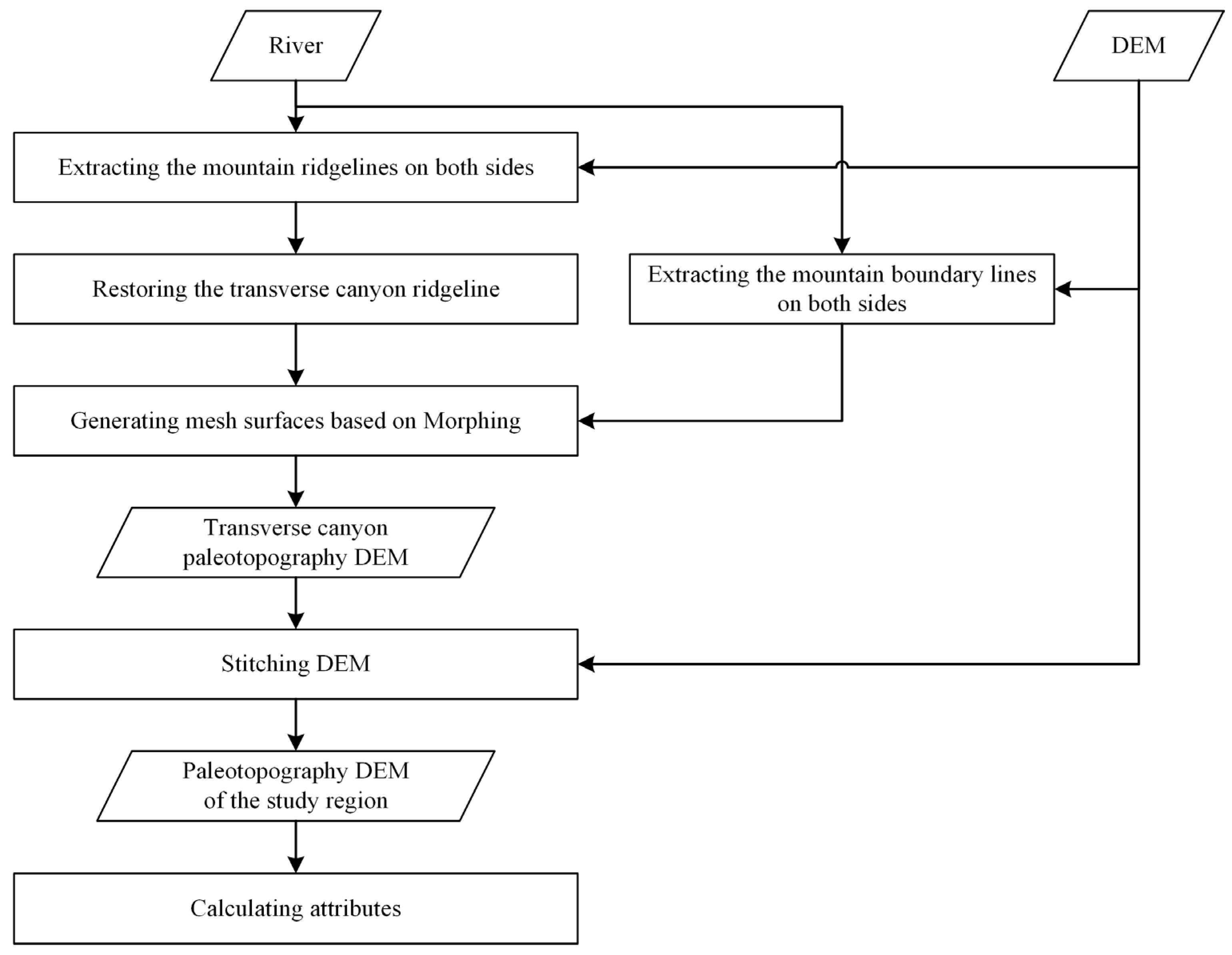
The proposed method consists primarily of the following steps (Figure 4): (1) restoring the ridgeline above the transverse canyon based on mountain ridgelines on both sides; (2) extracting the transverse canyon boundary lines on both sides; (3) generating the mesh surfaces using the morphing algorithm; (4) reconstructing a transverse canyon DEM by a spatial interpolation method and stitching the input DEM to obtain a paleotopographic DEM; and (5) calculating the spatial attributes. As an example study unit, the Tongluo Canyon (range ➃ in Figure 3 and henceforth referred to as C4) is used to illustrate the suggested technique in depth.

4.1. Restoring the Ridgeline above the Transverse Canyon

The ridgeline determines the antiquity of the canyon’s terrain. Prior to the construction of the transverse canyon, the stratigraphic distribution of the original bedrock mountains, which were mostly generated by folding or tectonic uplift, was the same, resulting in consistent original geomorphology and equally continuous original ridgelines. Consequently, the undulations of the eroded ridgeline above the transverse canyon and the bedrock mountains on both sides are remarkably constant, continuous, and comparable. This section formulates the technique of ridgeline restoration above the transverse canyon, which consists primarily of two steps: extracting the ridgelines of the mountains on both sides and replacing the missing ridgeline using the forward circle method.
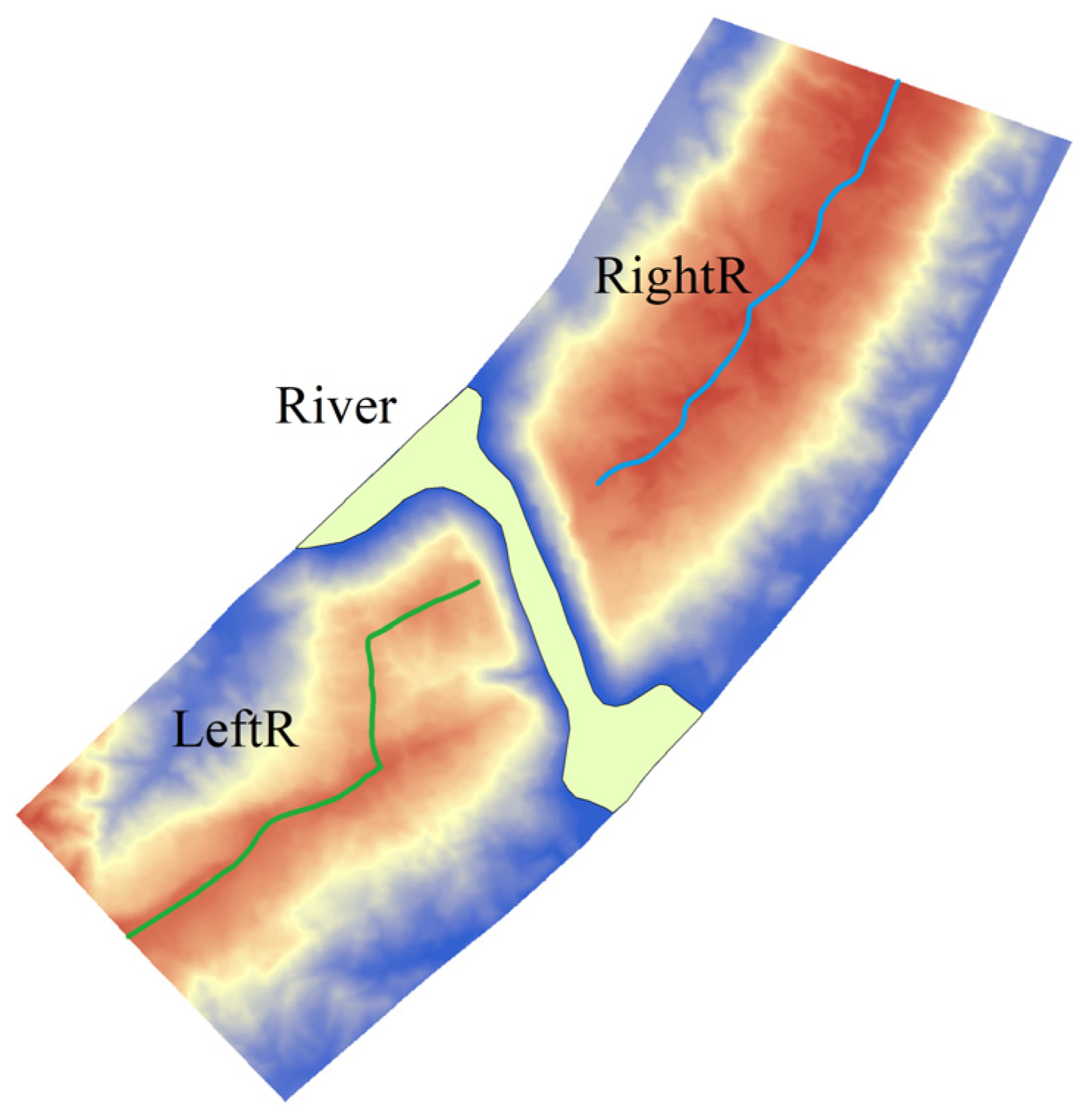
A critical requirement is the extraction of the ridgelines on both sides with precision. Currently, there are two kinds of methods for extracting ridgelines, depending on the terrain surface: geometric form analysis [55,56,57,58,59] and flow analysis [60,61,62,63]. The former pertains to digital contour data with an emphasis on geometry, while the latter pertains to DEM data with an emphasis on surface function. In consideration of precision and practicability, this work extracts mountain ridgelines using the Strahler [59] method from the previous methods. Figure 5 depicts the mountain ridgelines, LeftR and RightR, on both sides of C4.
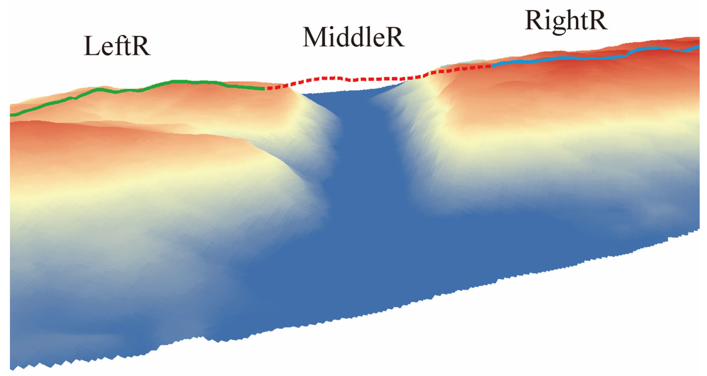
After precisely extracting the ridgelines at the summits of the mountains on both sides, the location of the missing ridgeline above the transverse canyon must be determined. According to the summary in Section 2.2, we may, of course, divide the missing ridgeline at its extreme or halfway to avoid addressing the monotony of the ridgelines on each side, which is caused by the differing locations of the transverse canyon. Therefore, the left portion of the split ridgeline receives elevation data from the ridgeline LeftR, while the right portion receives elevation data from RightR. First, based on the stack profiles of the ridgelines on both sides, fitting a polynomial function curve between the endpoints S_L and S_R and splitting it into two parts: MiddleR-L and MiddleR-R at the extreme point or midpoint L_P (Figure 6a), then obtaining elevation data from the ridgelines on both sides to update the curves MiddleR-L and MiddleR-R (Figure 6b). The main steps are as follows: (1) calculating the euclidean distance d on the XY plane and the absolute value ∆h of the elevation difference between the starting point and the ending point of the curve MiddleR-R, (2) drawing the geometric circle with d as the radius and any node on RightR as the center, and saving the intersection curve r i of the geometric circle and RightR into R = { r i | i = 1 , 2 , , N } ; where N is the number of curves in R , (3) selecting a curve r i from R whose difference between the absolute value of the elevation difference between the starting point and the ending point of this curve and ∆h is the smallest, (4) updating the elevation data on curve r i to curve MiddleR-R, and (5) upating the curve MiddleR-L according to steps (1)–(4). Finally, generate the ridgeline MiddleR above the transverse canyon by merging the curves MiddleR-R and MiddleR-L. Figure 7 shows the restored ridgeline above C4.

4.2. Generating the Boundary Lines on Both Sides of the Transverse Canyon

The size of the transverse canyon is governed by the boundary lines on the sheer cliffs on both sides. In past research, valley shoulder lines were identified from DEM data using terrain factors [64,65,66], slope variation [67], and picture edge extraction [68,69]. The aforementioned techniques are mostly applicable to the extraction of shoulder lines in the hilly loess zone but are unsuccessful for the extraction of boundary lines in isolated, sharply transverse canyons. This study constructs a buffer zone with uneven buffer distances on both sides based on the river’s centerline in the transverse canyon, with the buffer distance being the vertical distance between the ends of the ridgelines on both sides and the centerline. The boundary lines on both sides of the buffer zone will serve as the initial transect canyon boundary line, which must be optimized in the next step. Figure 8a,b depict the position and stack profile of the boundary lines on both sides of C4 as seen from above.
The initial boundary lines indicate that the extent of the transverse canyon is larger than its actual area and that both sides will exceed the original boundaries. Therefore, the superfluous curves must be removed. To extract the effective boundary lines for the transverse canyon, the cutoff points of the curves beyond the region must be precisely defined. Figure 8b depicts these sites as the first curved vertices at the ends of both sides of the arc. As seen in Figure 9a, cut points may be identified using the inflexion-point detection bending approach [70,71]. Figure 9b illustrates the 3D boundary lines of C4 after the cutoff.

4.3. Interpolating the Mesh Surface of the Transverse Canyon Base on Morphing

Morphing [72] is a method for examining morphological gradients, primarily used in computer image processing. It focuses on generating a more seamless transition between the original and goal images. We may recreate a 3D smooth surface using the morphing method to interpolate a sequence of transition curves with subtle form changes.
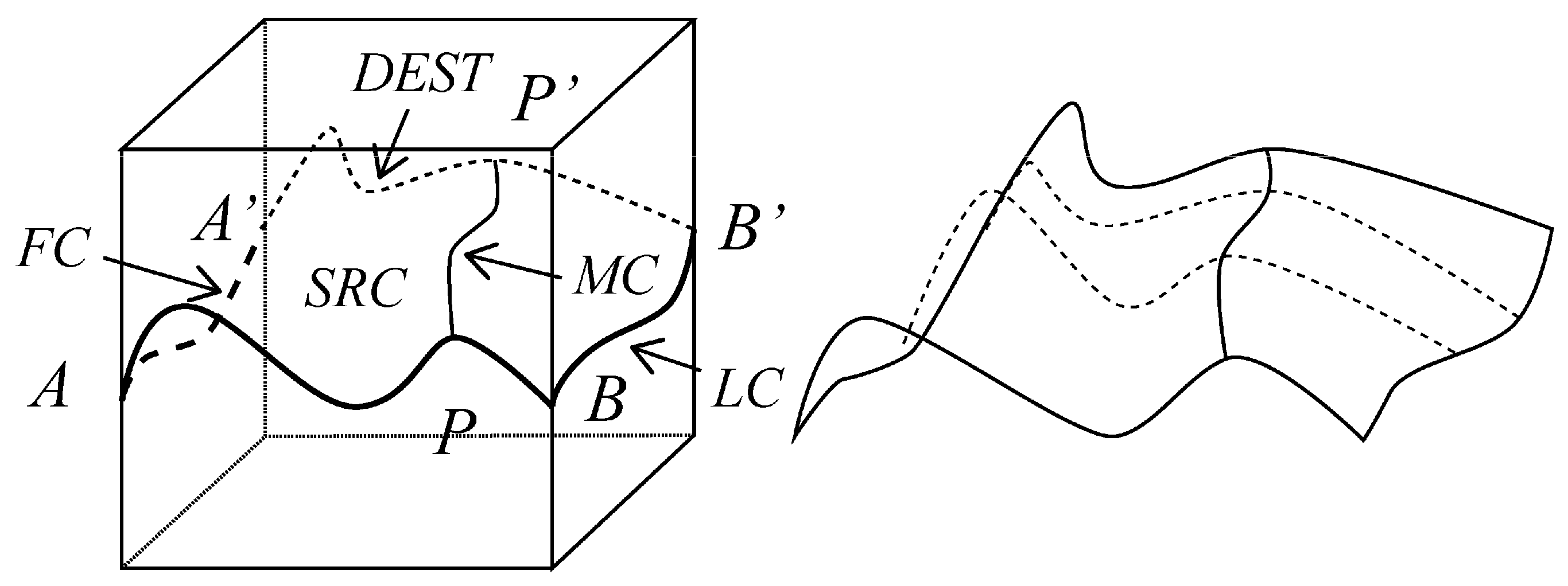
The morphing method has three fundamental components (Figure 10).
(1)
Start boundary (SRC): interpolation start line—directed curve AB (A is the starting point).
(2)
Target boundary (DEST): end line of interpolation—directed curve A′B′ (A′ is the beginning point).
(3)
Constraint boundaries (MC, FC, LC): regulate the trend of transition curves such as AA′, BB′, and PP′ throughout the interpolation process. The first constraint (FC) is associated with the beginning point, while the final constraint (LC) is associated with the finishing position. The constraint positioned between FC and LC is known as the intermediate constraint (MC).
To simplify the complicated morphing method, Ming and Yan [73] outlined four fundamental kinds (Figure 11), none of which must include intermediary constraint MCs, and the maximum number of boundaries is 4.
In the morphing method, the four-edge type (Figure 11a) is the ideal prototype, and all other types degenerate from it. LC or FC degenerates to a straight line in the three-edge form (Figure 11b). This study employs MiddleR as an intermediate constraint MC to divide the transverse canyon region into two sections, I and II, and both can be regarded as three-edge types. First, we get the coordinates of the endpoints on both sides of LeftV and RightV to linearly interpolate the boundary constraint line LR-V. Then regard LeftV, RightV, MiddleR, and LR-V as SRC, DEST, FC, and LC to use the four-edge interpolation method (Figure 12) to construct the transition curves TCS. Finally, apply the minimizing span length method [74] to connect all the transition curves in TCS with triangles and reconstruct the mesh surface.
The specific steps of four-edge interpolation method are as follows:
(1)
Constructing various sets of nodes. Separately saving the nodes on boundaries SRC, DEST, FC, and LC into SRC = { F f | f = 1 , 2 , , F N } ,   DEST = { G g | g = 1 , 2 , , G N } , FC = { P p | p = 1 , 2 , , P N } , and LC = { Q q | q = 1 , 2 , , Q N } ,   F f = ( x , y , z ) , G g = ( x , y , z ) , P p = ( x , y , z ) , and Q q = ( x , y , z ) . Where f , g , p , q mean the index of each node, F N , G N , P N , Q N are the number of nodes in each set and P N =   Q N , and x ,   y ,   z are the horizontal coordinate, longitudinal coordinate, and elevation of each node, respectively. In addition, F 1 , G 1 , P 1 ,and Q 1 are the starting node of each line, and F F N , G G N , P P N ,and Q Q N are the ending node of each line.
(2)
Utilizing a contouring method to match nodes. A node in SRC may correlate to many nodes in DEST if F N G N . This study matches nodes using the Minimizing Span Length technique [74].
(3)
Constructing the transition curves. Suppose a transition curve TC exists, then the node set is TC = { H h | h = 1 , 2 , , H N } , H h = ( x , y , z ) . Where h represents the node’s index, and H N =   F N if F N > G N ; H N = G N if F N G N . Using Equations (1) and (2), we can then determine the coordinate value of every node on TC.
{ H h ( x ) = ( 1 v ) F f ( x ) + v G g ( x ) H h ( y ) = ( 1 v ) F f ( y ) + v G g ( y ) H h ( z ) = ( 1 v ) F f ( z ) + v G g ( z )  
H h ( z ) = ( 1 u ) ( P p ( z ) H h ( z ) ) + u ( Q Q ( z ) H h ( z ) )
where Equation (1) calculates the unrestricted coordinates of the nodes on TC, and Equation (2) adjusts the elevation values of the nodes on TC. v describes how close the TC is to the SRC and DEST. When v = 0, the TC becomes the SRC. As v increases, the TC moves away from SRC and closer to DEST. When v = 1, the TC becomes DEST. Similarly, u describes how close the H h is to the H 1 and H H N .
(4)
Reconstructing the mesh surface. Saving each TC into TCS = { T t | t = 1 , 2 , , T N } , where t is the index of TC, and T N is the number of TCs in TCS.
This study takes the C4 region as an example to show the division outcome and the interpolation results of the transition curves and mesh surface (Figure 13).

4.4. Generating the Paleotopographic DEM of the Transverse Canyon

The paletopographic DEM of the transverse canyon is obtained by rasterizing the interpolated mesh surface from Section 4.3 to construct a DEM and sewing it to the input DEM. The key measures are:
(1)
Generating a DEM R_Dem via all mesh nodes using a spatial interpolation approach that is compatible with the input DEM. The extent of R_Dem is the same as the area of the transverse canyon, and the pixel is identical to the input DEM.
(2)
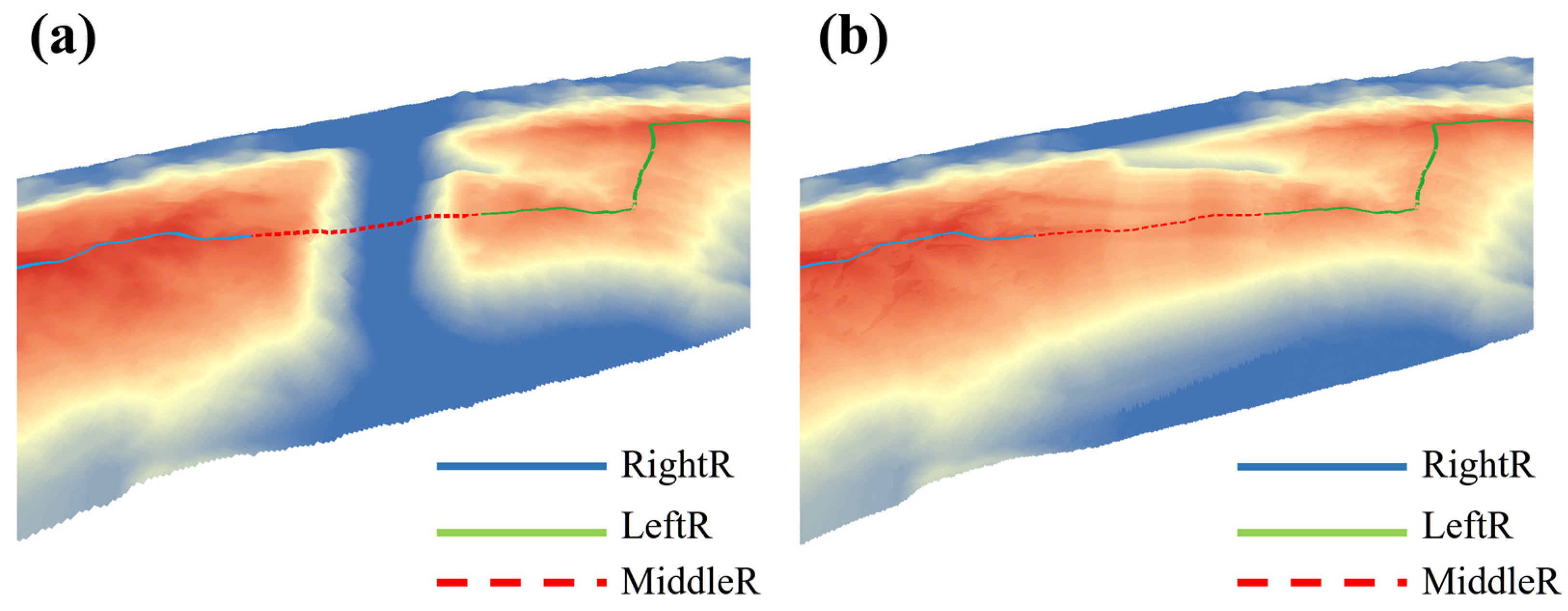
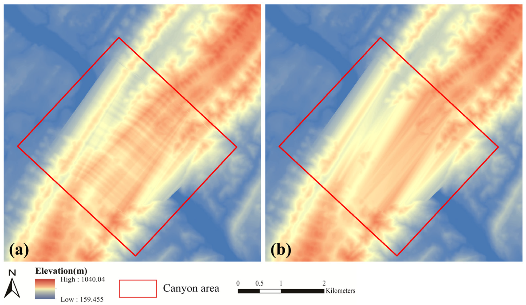
Applying the seamless stitching algorithm [75] to R_Dem to produce the paleotopographic DEM of the transverse canyon (Figure 14).

4.5. Calculating Spatial Attributes of the Transverse Canyon

This section is intended to compute the spatial characteristics of each transverse canyon based on the reconstructed DEM in order to have a thorough understanding of their differences. Length, depth, breadth, aspect ratio [76], central coordinates, area in plan-view, surface area, and volume are the primary characteristics of a transverse canyon. This study primarily focused on determining the surface area and volume. Xu et al. [77] supplied the particular calculation techniques for the first six components. The surface and volume calculations are detailed in full below.

4.5.1. Surface Area

The surface corresponds to the extracted mesh surface from Section 4.3. The surface area is the total value obtained by summing the areas of each triangle on the mesh surface.

4.5.2. Volume

The volume of the transverse canyon is equivalent to the volume of the gap between the palaeotopography of the canyon and the river level. We utilize the transverse canyon region to trim the input DEM to get the current DEM and then weld the result to the restored DEM to create a closed body. The volume of the closed body equals that of the transverse canyon.

5. Results

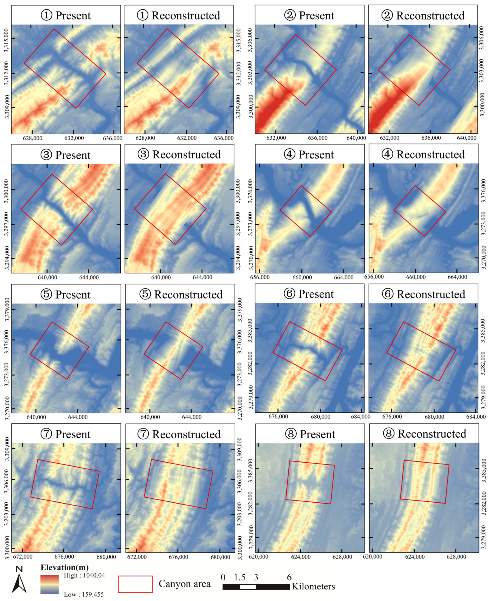
Figure 15 shows the results of reconstructing the paleotopography of eight transverse canyons in the study region using the method described in Section 4.1, Section 4.2, Section 4.3 and Section 4.4. The method suggested in this study could reconstruct the paleotopography of a transverse canyon eroded at varying intensities by comparing the reconstruction findings completely. However, the amount of erosion has a detrimental effect on the accuracy of the reconstruction, and there is a clear distinction between the several transverse canyons. Obviously, each transverse canyon’s paleotopographic DEM may still be utilized to mimic headward erosion.
Figure 16 depicts the paleotopography of the study region following the reconstruction of all transverse canyons. The outcome reproduces the ancient pattern of the eastern Sichuan fold belt, which gives essential information for inferring the paleodrainage pattern. Table 1 displays the values of each transverse canyon’s spatial properties. The aspect ratios of transverse canyons in the study region vary from 0.14 to 0.21, and the difference between canyons ➀, ➁, ➂, ➃, ➅, and ➆ is less than 0.03. The statistics may suggest that the impact of river erosion on the region’s mountains is relatively uniform.

6. Discussion and Applications

6.1. Factors Affecting the Method

6.1.1. Dislocated Mountains

The mountains on both sides of the transverse canyon will shift vertically, horizontally, or obliquely as a result of faulting. The ridgelines on both sides will travel to the present position synchronously and with a pretty full spatial shape. Before using the method described in this paper to reconstruct paleotopography, it is essential to restore the original location of the mountains on both sides.

6.1.2. Erosion Gullies

On the surface of mountains generated by tectonic uplift, numerous erosion gullies may arise owing to precipitation, rockfall collapse, and river erosion. The existence of erosion gullies influences the accuracy of the transverse canyon’s reconstruction. If the erosion gully inclines too deeply, the ridgeline may shift [78]. If transverse canyon boundary lines travel through an erosion gully, their concave portion often reflects the current canyon shape, causing the recovered topography to differ from the palaeotopography and the computed volumes to be erroneous.
For the erosion gullies on the sides of the transverse canyon, there are three potential solutions: (1) Gradually moving the boundary lines away from the transverse canyon region and including the erosion gullies into the restoring area. This proposed method is effective for eroding gullies with shallow incisions. Consider that the erosion gullies are excessively deep or likely to create a river valley. This strategy is useless because the boundary lines will be situated too far from the transverse canyon region. (2) Inferring the size of each erosion gully from the profile of the boundary line stack and building a smooth curve to remove it. This proposed method assures that the restored result conforms to the paleotopography of the transverse canyon; nevertheless, it may leave gaps between the recovered DEM and the input DEM, which can lead to stitching problems in the future. (3) Initially ignoring the erosion gullies, after rebuilding the transverse canyon using the techniques outlined in this study, the erosion gullies may be identified and eliminated. However, the algorithm for recognizing and eliminating erosion gullies is sophisticated, and additional testing of its practicality is required.

6.1.3. Different Types in Morphing

Section 4.3 describes four fundamental types of the morphing technique. Each kind has distinct application circumstances and interpolates the transition curve in a distinct manner. Theoretically, the better the paleotopography will be reconstructed, the more constrained boundaries should be applied. In this study, the use of the three-edge type is predicated on the reconstruction of the ridgeline above the transverse canyon. However, it is not always possible to extract ridgelines from both sides of a mountain. When confronted with this difficulty, we may interpolate the mesh surface approximately by applying the two-opposite-edge type to the boundary lines on both sides. Obviously, the two-opposite-edge type does not represent the undulations of the ridgelines above the palaeotopography and is only applicable when the ridgelines on both sides of the mountain are uniformly undulating. Figure 17 displays the outcomes of restoring transverse canyon ➂ in the study region using the three-edge and two-opposite-edge kinds.

6.1.4. DEM “Jump”

For the reconstructed transverse canyon ➁, ➂ and ➄ in Figure 15, we can observe that the lateral edges of the canyon are light blue and the lateral edges of the river are dark blue, showing a noticeable “jump”. As this study only restored the topography of the transverse canyon area, the river valley on either side had not been restored, resulting in a height difference between the two. When the river valley’s width on either side is greater than the width of the transverse canyon or the boundary constraint line LR-V (Figure 13) passes through the river valley parallel to the mountain, this “jump” will reduce or be absent (the transverse canyons ➅, ➆, and ➇). Of course, the method proposed in this study can apply to other river valley regions, but the required terrain feature lines are different from those of the transverse canyon. The paleotopography above the river valley can be quickly reconstructed by extracting the shoulder lines along both sides of the valley and using the morphing two-opposite-edge type.

6.2. Applicability of the Method for Other Secondary Valleys

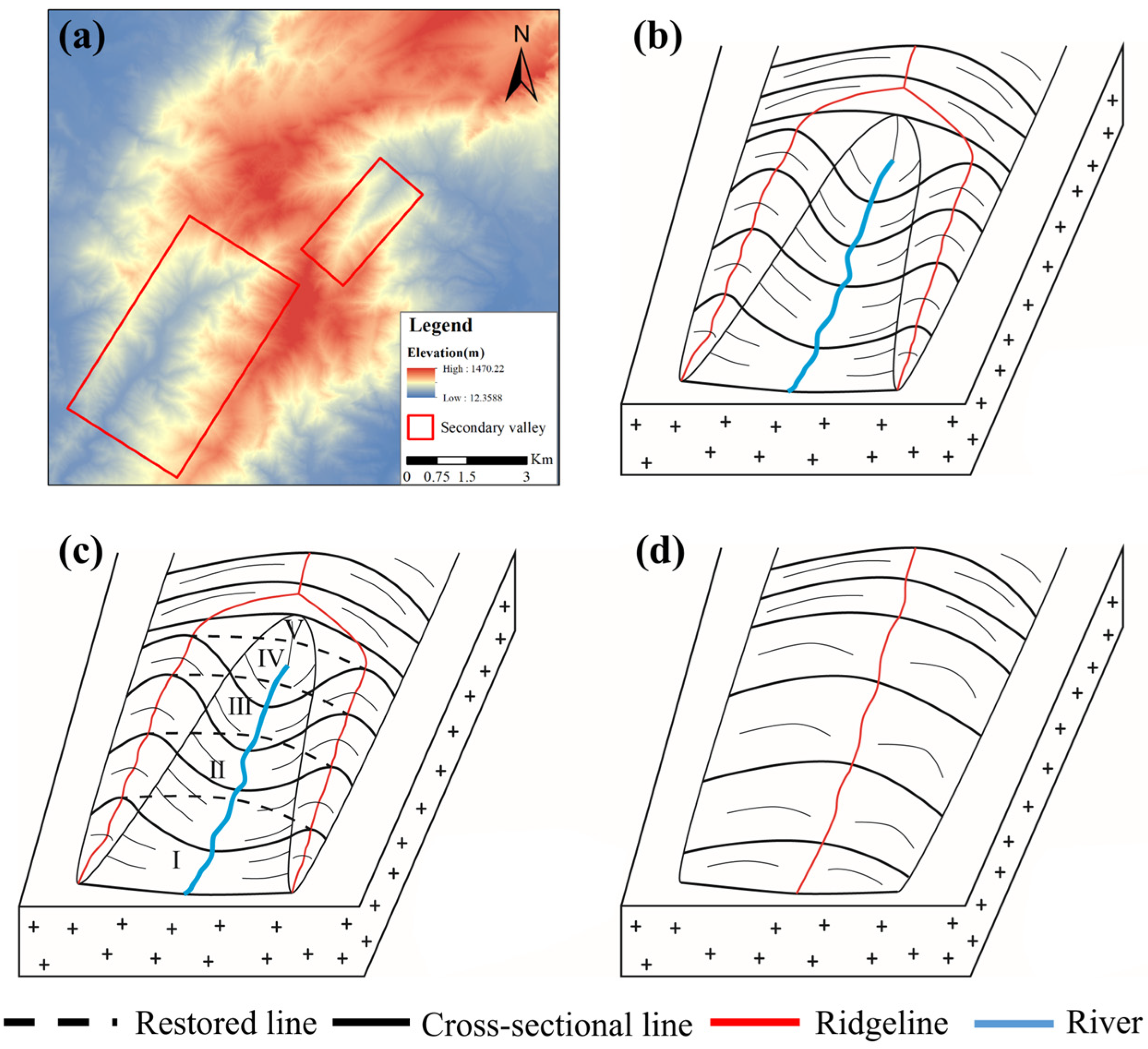
The transverse canyon is a secondary valley generated by river erosion. In contrast, weaker rocks, fault development, and surface runoff will contribute to the formation of other secondary valley types in tectonically elevated mountain regions. The link between each secondary valley’s path and the mountains may be vertical, oblique, or parallel. In addition to secondary valleys with a vertical or diagonal connection, such as the transverse canyon, the approach presented in this paper may also be used for secondary valleys with a parallel relationship. On top of the anticline on Lushan Mountain in Jiangxi Province, Figure 18a depicts an example of a secondary valley that runs parallel to its mountain. The simulation model may be shown in Figure 18b. Figure 19a illustrates the simulation model of the secondary valley parallel to its mountain, situated on one wing of the anticline on Lushan Mountain. Like the transverse canyon, we first extract the ridgelines on the hills on both sides of the secondary valley, then build a series of parallel cross-sectional lines along the mountain trend, and then fit the missing portion of each cross-sectional line based on their monotony. Subsequently, we split the whole secondary valley region into several four-edge subareas based on the recovered cross-sectional lines and ridgelines. In addition, we reconstruct the paleotopography of each subarea using the morphing four-edge type. Figure 18d and Figure 19c replicate the secondary valley’s reconstructed paleotopography.
In conclusion, the morphing method is applicable for reconstructing the paleotopography of all secondary valley types. The native valleys, however, cannot tolerate this strategy. Native valleys are valleys developed by internal geological forces, such as the syncline valley produced by folding. Their restoration technique focuses on reproducing the valleys’ progression from existence to extinction, which is the opposite of the secondary valley.

6.3. Application Cases of the Reconstructed Paleotopography

6.3.1. Headward Erosion Simulation

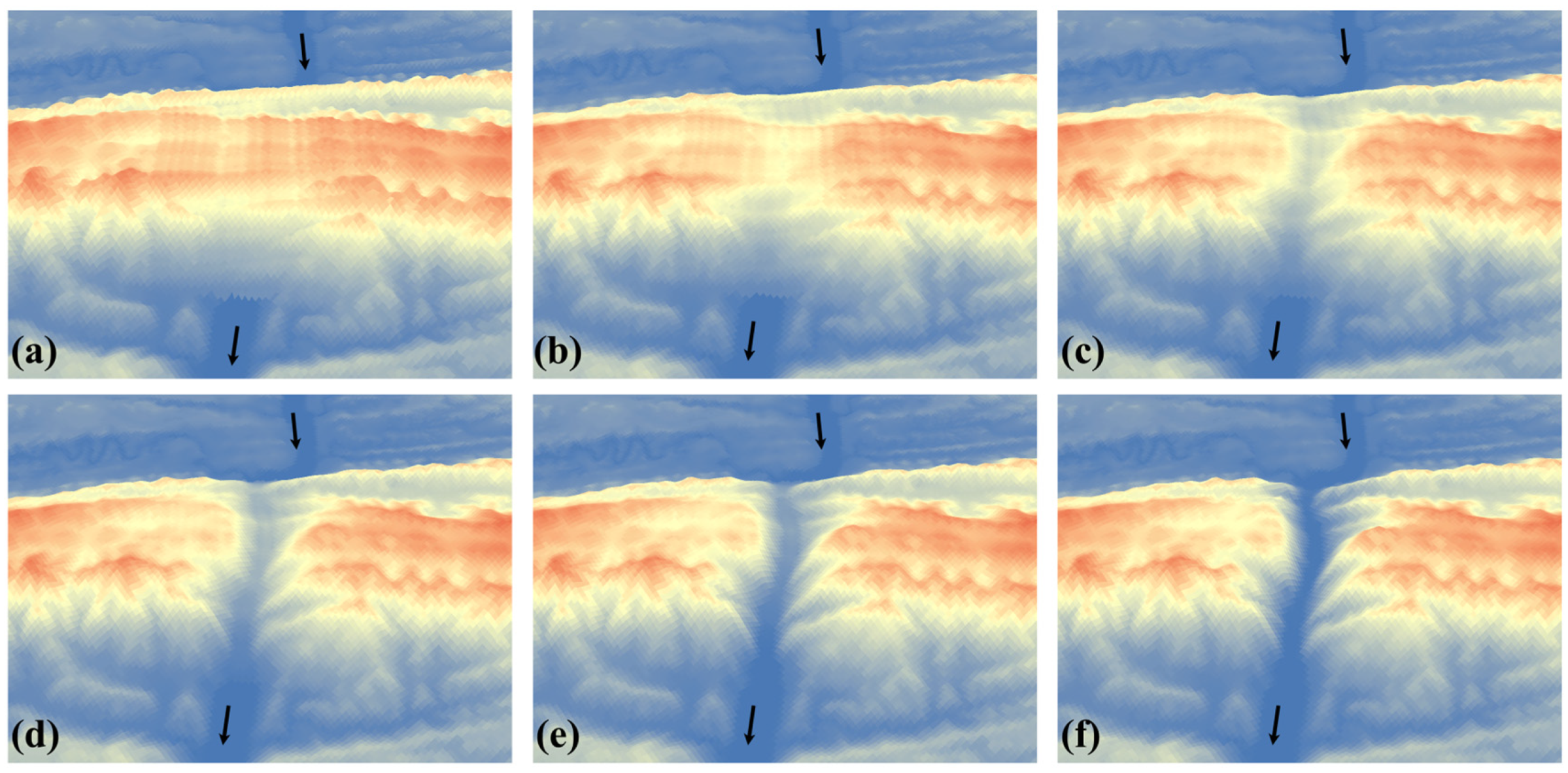
Headward erosion refers to river surface erosion that causes a valley to spread and grow in the opposite direction of the river’s flow. Its final location is the river’s watershed. To validate the experimental findings of this investigation, we used the Modern Catch Landform Evolution Model (MCLEM) [79] to model the headward erosion process of transverse canyon ➂ in the study region (Figure 20). The model shown above integrated the functions of tectonic elevation, weathering, hillslope, and river erosion; however, we only addressed fluvial erosion. According to the test results, our knowledge of geomorphological processes, particularly the erosion and formation processes of the transverse canyon, may be expanded.

6.3.2. Analysis of Paleodrainage Pattern

After reconstructing the paleotopography of all transverse canyons, we could derive the DEM of the pre-mountain penetration era and extract the drainage networks of that time period. In this study, drainage networks are extracted using the Overland Flow Algorithm of Surface Runoff [80]. This method consists mostly of the processes of fill treatment, flat land treatment, calculation of river flow direction and fiver flow accumulation, and river vector line extraction. Figure 21 depicts the drainage networks in the study region with river flow accumulations over 50,000 m3 prior to the existence of all transverse canyons. Compared to the existing drainage networks in the study region (Figure 1b), the drainage networks on both sides evolved following the valley trend before the mountains were traversed. With river capture and forward erosion, they are eventually joined. This experimental finding may validate the theory that the tectonic uplift in eastern Sichuan separates the Yangtze’s middle and lower drainage from its upper drainage [51] and that the upper drainage crosses the whole barrier tectonic zone to join the middle drainage [27,32]. Obviously, the construction process of transverse canyons and drainage networks in the investigated region is dynamic and chronologically related. According to the findings of geographers’ study, we may dynamically change the existence periods of various transverse canyons and extract drainage networks in different time periods to invert the history of drainage.

6.3.3. Three-Dimensional Model of the Transverse Canyon

The 3D model of the transverse canyon may visually represent its location, geometric shape, and attribute data in three-dimensional space. In addition, the 3D model may be used to determine volume, surface area, and the finite element technique. Using the grid points of the present DEM and paleotopographic DEM of the transverse canyon, we build a Delaunay triangulation network to generate a 3D solid model. Figure 22 depicts the 3D solid model of C4 in the study region.

6.4. Comparison between the Proposed Method and the Existing Methods

First, different geological processes have various driving forces and development mechanisms, so the terrain changes caused by them need different terrain restoration methods for reconstruction [37,42,44,46,47]. At present, the residual thickness method [38], low-temperature thermal chronology [50], and river power erosion model [81] related to the restoration of valley paleotopography are mainly used for regional paleotopography restoration in large basins or orogenic belts. The relevant research object is the current terrain formed by superimposed weathering, denudation, and river erosion under tectonic uplift. The method in this study is mainly aimed at a small local object—a transverse canyon whose landform is primarily formed by river capture [7,20,21] or headward erosion [3,9], belonging to a river erosion valley. Its development mechanism, geographical location, and research scale differ from the above methods, which gives it unique research value.
Secondly, the regional paleotopography was formed by various internal and external geological processes [82]. The proposed method does not conflict with the existing methods but provides an effective complementary means. For the transverse canyon, which runs through the two basins, we could restore its paleotopography so that the two basins can be separated and kept intact. Then, we could use existing methods to restore the paleotopography for each complete basin, and the restoration result would be better. The method in this study can be combined with other methods and used by superposition to make the detailed restoration of regional paleotopography more realistic.
Finally, this proposed method mainly proceeds from the continuity and consistency of terrain features to reconstruct paleotopography but lacks age information. Of course, the reconstruction results support the practical calculation of the canyon erosion amount. If the denudation rate data is further considered, it can also support the calculation of denudation time and the spatio-temporal simulation of the landscape evolution process.

7. Conclusions

Based on vector river data and DEM, this work proposes an automatic method for reconstructing the paleotopography of the transverse canyon. First, we restored the ridgeline above the transverse canyon based on the ridgelines on both sides of the transverse canyon and extracted the boundary lines on both sides using the river buffer zone as a guide. We then created the paleotopographic DEM of the study region by sewing the paleotopographic DEM of each transverse canyon to the input DEM based on the three-edge type of the morphing technique. The rebuilt DEMs of transverse canyons enabled accurate calculations of spatial characteristics such as surface area and volume.
This work reconstructed the paleotopography of eight typical transverse canyons inside the comb-like fold zone in northeastern Chongqing. In addition, we discussed the impact of dislocated mountains, erosion gullies, and different types in the Morphing method for the paleotopographic reconstruction of the transverse canyon, demonstrated the applicability of this method in reconstructing other secondary valleys, and applied the reconstructed paleotopographic DEM of transverse canyons to simulate headward erosion processes, analyze palaeodrainage patterns, and construct 3D solid models.
This paper proposes a strategy for reconstructing the paleotopography of the transverse canyon, a secondary valley formed by river erosion. It also applies to other oblique or parallel secondary valleys. Despite the fact that the paleotopography in the study region may be influenced by other variables, such as weathering and tectonic elevation, the proposed method is still a valuable addition to the paleotopographic reconstruction. Obviously, future research will examine the paleotopographic reconstruction of the transverse canyon or other secondary valleys in more complicated settings.

Author Contributions

Y.S.: Conceptualization, Methodology, Writing—original draft, Data curation, Visualization, Investigation, Writing—review & editing; A.L.: Conceptualization, Methodology, Supervision, Writing—review & editing; S.X.: Data curation, Writing—review & editing; X.X.: Supervision, Writing—review & editing. All authors have read and agreed to the published version of the manuscript.

Funding

This study was supported by the National Natural Science Foundation of China (Project No. 41971068, 41771431) and the National Key R&D Program of China (Project No. 2021YFE0112300).

Data Availability Statement

The raw data supporting the conclusions of this article will be made available by the authors, without undue reservation.

Conflicts of Interest

The authors declare no conflict of interest.

Computer Code and Software

Name of code: TransverseCanyonRestore; Version: 1.0; Hardware required: Transverse-CanyonRestore was run on a computer with 2 cores (1.8 GHz each) and 4 GB of RAM, which is a basic running requirement for Visual studio; Software required: TransverseCanyonRestore was interpreted with Visual Studio (2012 or version above); Program Language: the code is written in C#; Program size: 108 MB; Details on how to access the source code: the source files of the Transver-seCanyonRestore can be downloaded from github: https://github.com/hakertop/TransverseCanyonRestore.git (accessed on 6 August 2022).

References

  1. English, O. Oxford English Dictionary. In Encyclopedia of Swearing; Routledge: London, UK, 1976; p. 334. [Google Scholar]
  2. Yan, Q.; Iwasaki, T.; Stumpf, A.; Belmont, P.; Parker, G.; Kumar, P. Hydrogeomorphological Differentiation between Floodplains and Terraces. Earth Surf. Process. Landf. 2018, 43, 218–228. [Google Scholar] [CrossRef] [Green Version]
  3. Micallef, A.; Marchis, R.; Saadatkhan, N.; Clavera-Gispert, R.; Pondthai, P.; Everett, M.E.; Avram, A.; Timar-Gabor, A.; Cohen, D.; Trapani, R.P.; et al. Box Canyon Erosion along the Canterbury Coast (New Zealand): A Rapid and Episodic Process Controlled by Rainfall Intensity and Substrate Variability. Earth Surf. Dyn. 2020. [Google Scholar] [CrossRef]
  4. Ansari, S.; Rennie, C.D.; Venditti, J.G.; Kwoll, E.; Fairweather, K. Shore-Based Monitoring of Flow Dynamics in a Steep Bedrock Canyon River. E3S Web Conf. 2018, 40, 06025. [Google Scholar] [CrossRef] [Green Version]
  5. Cook, K.L.; Whipple, K.X.; Heimsath, A.M.; Hanks, T.C. Rapid Incision of the Colorado River in Glen Canyon–Insights from Channel Profiles, Local Incision Rates, and Modeling of Lithologic Controls. Earth Surf. Process. Landf. 2009, 34, 994–1010. [Google Scholar] [CrossRef]
  6. Glade, R.C.; Shobe, C.M.; Anderson, R.S.; Tucker, G.E. Canyon Shape and Erosion Dynamics Governed by Channel-Hillslope Feedbacks. Geology 2019, 47, 650–654. [Google Scholar] [CrossRef]
  7. Bracciali, L.; Najman, Y.; Parrish, R.R.; Akhter, S.H.; Millar, I. The Brahmaputra Tale of Tectonics and Erosion: Early Miocene River Capture in the Eastern Himalaya. Earth Planet. Sci. Lett. 2015, 415, 25–37. [Google Scholar] [CrossRef] [Green Version]
  8. Mitchell, N.C. Interpreting Long-Profiles of Canyons in the USA Atlantic Continental Slope. Mar. Geol. 2005, 214, 75–99. [Google Scholar] [CrossRef]
  9. Green, A.N.; Goff, J.A.; Uken, R. Geomorphological Evidence for Upslope Canyon-Forming Processes on the Northern KwaZulu-Natal Shelf, SW Indian Ocean, South Africa. Geo-Mar. Lett. 2007, 27, 399–409. [Google Scholar] [CrossRef]
  10. Reolid, J.; Bialik, O.M.; Puga-Bernabéu, Á.; Zilberman, E.; Cardenal, J.; Makovsky, Y. Evolution of a Miocene Canyon and Its Carbonate Fill in the Pre-Evaporitic Eastern Mediterranean. Facies 2022, 68, 6. [Google Scholar] [CrossRef]
  11. Schildgen, T.F.; Ehlers, T.A.; Whipp, D.M., Jr.; van Soest, M.C.; Whipple, K.X.; Hodges, K.V. Quantifying Canyon Incision and Andean Plateau Surface Uplift, Southwest Peru: A Thermochronometer and Numerical Modeling Approach. J. Geophys. Res.-Earth Surf. 2009, 114, F04014. [Google Scholar] [CrossRef]
  12. Wang, P.; Scherler, D.; Liu-Zeng, J.; Mey, J.; Avouac, J.-P.; Zhang, Y.; Shi, D. Tectonic Control of Yarlung Tsangpo Gorge Revealed by a Buried Canyon in Southern Tibet. Science 2014, 346, 978–981. [Google Scholar] [CrossRef] [PubMed] [Green Version]
  13. Maw, G. III.—Notes on the Comparative Structure of Surfaces Produced by Subaërial and Marine Denudation. Geol. Mag. 1866, 3, 439–451. [Google Scholar] [CrossRef] [Green Version]
  14. Gardner, J.V.; Armstrong, A.A.; Calder, B.R. Hatteras Transverse Canyon, Hatteras Outer Ridge and Environs of the U.S. Atlantic Margin: A View from Multibeam Bathymetry and Backscatter. Mar. Geol. 2016, 371, 18–32. [Google Scholar] [CrossRef] [Green Version]
  15. Hopkins, W.I. —On the Geological Structure of the Wealden District and of the Bas Boulonnais. Trans. Geol. Soc. Lond. 1845, 7, 1–51. [Google Scholar] [CrossRef] [Green Version]
  16. Thornbury, W.D. Principles of Geomorphology; John Wiley and Sons: New York, NY, USA, 1954; pp. 123–126. [Google Scholar]
  17. Larson, P.H.; Meek, N.; Douglass, J.; Dorn, R.I.; Seong, Y.B. How Rivers Get Across Mountains: Transverse Drainages. Ann. Am. Assoc. Geogr. 2017, 107, 274–283. [Google Scholar] [CrossRef]
  18. Douglass, J.; Schmeeckle, M. Analogue Modeling of Transverse Drainage Mechanisms. Geomorphology 2007, 84, 22–43. [Google Scholar] [CrossRef]
  19. Douglass, J.; Meek, N.; Dorn, R.I.; Schmeeckle, M.W. A Criteria-Based Methodology for Determining the Mechanism of Transverse Drainage Development, with Application to the Southwestern United States. Geol. Soc. Am. Bull. 2009, 121, 586–598. [Google Scholar] [CrossRef]
  20. Johnson, B. Stream Capture and the Geomorphic Evolution of the Linville Gorge in the Southern Appalachians, USA. Geomorphology 2020, 368, 107360. [Google Scholar] [CrossRef]
  21. Fan, N.; Kong, P.; Robl, J.C.; Zhou, H.; Wang, X.; Jin, Z.; Liu, X. Timing of River Capture in Major Yangtze River Tributaries: Insights from Sediment Provenance and Morphometric Indices. Geomorphology 2021, 392, 107915. [Google Scholar] [CrossRef]
  22. Pan, B.; Hu, Z.; Wang, J.; Vandenberghe, J.; Hu, X.; Wen, Y.; Li, Q.; Cao, B. The Approximate Age of the Planation Surface and the Incision of the Yellow River. Paleogeogr. Paleoclimatol. Paleoecol. 2012, 356, 54–61. [Google Scholar] [CrossRef]
  23. Cheng, S.; Deng, Q.; Zhou, S.; Yang, G. Strath Terraces of Jinshaan Canyon, Yellow River, and Quaternary Tectonic Movements of the Ordos Plateau, North China. Terra Nova 2002, 14, 215–224. [Google Scholar] [CrossRef]
  24. Hippolyte, J.-C.; Clauzon, G.; Suc, J.-P. Messinian-Zanclean Canyons in the Digne Nappe (Southwestern Alps): Tectonic Implications. Bull. Soc. Geol. Fr. 2011, 182, 111–132. [Google Scholar] [CrossRef] [Green Version]
  25. Yang, Z.; Shen, C.; Ratschbacher, L.; Enkelmann, E.; Jonckheere, R.; Wauschkuhn, B.; Dong, Y. Sichuan Basin and beyond: Eastward Foreland Growth of the Tibetan Plateau from an Integration of Late Cretaceous-Cenozoic Fission Track and (U-Th)/He Ages of the Eastern Tibetan Plateau, Qinling, and Daba Shan. J. Geophys. Res.-Solid Earth 2017, 122, 4712–4740. [Google Scholar] [CrossRef]
  26. Clark, M.K.; Schoenbohm, L.M.; Royden, L.H.; Whipple, K.X.; Burchfiel, B.C.; Zhang, X.; Tang, W.; Wang, E.; Chen, L. Surface Uplift, Tectonics, and Erosion of Eastern Tibet from Large-Scale Drainage Patterns. Tectonics 2004, 23, TC1006. [Google Scholar] [CrossRef] [Green Version]
  27. Clift, P.D.; Carter, A.; Wysocka, A.; Van Hoang, L.; Zheng, H.; Neubeck, N. A Late Eocene-Oligocene through-Flowing River between the Upper Yangtze and South China Sea. Geochem. Geophys. Geosyst. 2020, 21, e2020GC009046. [Google Scholar] [CrossRef]
  28. Alvarez, W. Drainage on Evolving Fold-Thrust Belts: A Study of Transverse Canyons in the Apennines. Basin Res. 1999, 11, 267–284. [Google Scholar] [CrossRef]
  29. Li, J.; Xie, S.; Kuang, M. Geomorphic Evolution of the Yangtze Gorges and the Time of Their Formation. Geomorphology 2001, 41, 125–135. [Google Scholar] [CrossRef]
  30. Darling, A.; Whipple, K. Geomorphic Constraints on the Age of the Western Grand Canyon. Geosphere 2015, 11, 958–976. [Google Scholar] [CrossRef] [Green Version]
  31. Ganjoo, R.K. The Vale of Kashmir: Landform Evolution and Processes. In Landscapes and landforms of India; Springer: Berlin/Heidelberg, Germany, 2014; pp. 125–133. [Google Scholar]
  32. Zheng, H.; Clift, P.D.; Wang, P.; Tada, R.; Jia, J.; He, M.; Jourdan, F. Pre-Miocene Birth of the Yangtze River. Proc. Natl. Acad. Sci. USA 2013, 110, 7556–7561. [Google Scholar] [CrossRef] [PubMed] [Green Version]
  33. Wang, X.; Bing, H.; Wu, Y.; Zhou, J.; Zhu, H.; Wu, Y.; Sun, H. Water Quality Variation and Its Conditioning Factors in the Three Gorges Reservoir, China. J. Water Clim. Chang. 2021, 12, 1694–1707. [Google Scholar] [CrossRef]
  34. Tao, Y.; Wang, Y.; Rhoads, B.; Wang, D.; Ni, L.; Wu, J. Quantifying the Impacts of the Three Gorges Reservoir on Water Temperature in the Middle Reach of the Yangtze River. J. Hydrol. 2020, 582, 124476. [Google Scholar] [CrossRef]
  35. Tang, M.; Xu, Q.; Huang, R. Site Monitoring of Suction and Temporary Pore Water Pressure in an Ancient Landslide in the Three Gorges Reservoir Area, China. Environ. Earth Sci. 2015, 73, 5601–5609. [Google Scholar] [CrossRef]
  36. Tang, H.; Wasowski, J.; Juang, C.H. Geohazards in the Three Gorges Reservoir Area, China–Lessons Learned from Decades of Research. Eng. Geol. 2019, 261, 105267. [Google Scholar] [CrossRef]
  37. Yu, T.; Liu, H.; Liu, B.; Tang, S.; Tang, Y.; Yin, C. Restoration of Karst Paleogeomorphology and Its Significance in Petroleum Geology—Using the Top of the Middle Triassic Leikoupo Formation in the Northwestern Sichuan Basin as an Example. J. Pet. Sci. Eng. 2022, 208, 109638. [Google Scholar] [CrossRef]
  38. Coleman, M.L.; Niemann, J.D.; Jacobs, E.P. Reconstruction of Hillslope and Valley Paleotopography by Application of a Geomorphic Model. Comput. Geosci. 2009, 35, 1776–1784. [Google Scholar] [CrossRef]
  39. Xiao, D.; Tan, X.; Fan, L.; Zhang, D.; Nie, W.; Niu, T.; Cao, J. Reconstructing Large-Scale Karst Paleogeomorphology at the Top of the Ordovician in the Ordos Basin, China: Control on Natural Gas Accumulation and Paleogeographic Implications. Energy Sci. Eng. 2019, 7, 3234–3254. [Google Scholar] [CrossRef] [Green Version]
  40. Lv, C.; Zhang, G.; Yao, Y.; Wu, S. Tectonic Evolution of the Wanan Basin, Southwestern South China Sea. Acta Geol. Sin. Engl. Ed. 2014, 88, 1120–1130. [Google Scholar] [CrossRef]
  41. Fu, X.Y.; Yang, Y.; Huang, Y.G.; Hao, L. Palaeomorphologic Reconstruction of Ordovician Karst in Southern Sulige Gasfield and Its Effect on Reservoir Distribution. Nat. Gas. Explor. Dev. 2014, 37, 1–4. (In Chinese) [Google Scholar]
  42. Wu, J.; Yang, H.; Xu, D. Introduction to the Recovery and Technology of Palaeogeomorphology in Sedimentary Basins. Adv. Mater. Res. 2015, 1073–1076, 2025–2030. [Google Scholar] [CrossRef]
  43. Sui, L.; Yang, W.; Song, B.; Wen, Q.; Sha, Z. Quantitative Restoration of Tongbomiao Formation Paleogeomorphology and Its Geological Significance in Tanan Depression. In Proceedings of the International Field Exploration and Development Conference, Xi’an, China, 16–18 October 2019; Springer: Berlin/Heidelberg, Germany, 2019; pp. 3309–3322. [Google Scholar] [CrossRef]
  44. Melo, A.H.; Magalhães, A.J.C.; Menegazzo, M.C.; Fragoso, D.G.C.; Florencio, C.P.; Lima-Filho, F.P. High-Resolution Sequence Stratigraphy Applied for the Improvement of Hydrocarbon Production and Reserves: A Case Study in Cretaceous Fluvial Deposits of the Potiguar Basin, Northeast Brazil. Mar. Pet. Geol. 2021, 130, 105124. [Google Scholar] [CrossRef]
  45. Hosseini, K.; Rezaee, P.; Kazem Shiroodi, S.; Moeini, M. Tectono-Sedimentary Evolution of the Maastrichtian Deposits in Western Part of Fars Area in a High Resolution Sequence Stratigraphic Framework. J. Pet. Res. 2021, 31, 146–153. [Google Scholar] [CrossRef]
  46. Huang, H.; Luo, Q. Mesozoic Group Denudation Recover and Its Petroleum Geologic Significations in the West Qaidam Basin. Pet. Explor. Dev. 2006, 33, 44. (In Chinese) [Google Scholar]
  47. Ding, R.; Chang, Y.; Min, K.; Xu, C.; Wang, W. Post-Orogenic Topographic Evolution of the Dabie Orogen, Eastern China: Insights from Apatite and Zircon (U-Th)/He Thermochronology. Geomorphology 2021, 374, 107487. [Google Scholar] [CrossRef]
  48. Braun, J.; Robert, X. Constraints on the Rate of Post-Orogenic Erosional Decay from Low-Temperature Thermochronological Data: Application to the Dabie Shan, China. Earth Surf. Process. Landf. 2005, 30, 1203–1225. [Google Scholar] [CrossRef]
  49. Wei, W.; Zuyi, Z. Reconstruction of Palaeotopography from Low-Temperature Thermochronological Data. Geol. Soc. Lond. Spec. Publ. 2009, 324, 99–110. [Google Scholar] [CrossRef]
  50. Jiao, R.; Yang, R.; Yuan, X. Incision History of the Three Gorges, Yangtze River Constrained From Inversion of River Profiles and Low-Temperature Thermochronological Data. J. Geophys. Res.-Earth Surf. 2021, 126, 2020JF005767. [Google Scholar] [CrossRef]
  51. Stokes, M.; Mather, A.E. Tectonic Origin and Evolution of a Transverse Drainage: The Río Almanzora, Betic Cordillera, Southeast Spain. Geomorphology 2003, 50, 59–81. [Google Scholar] [CrossRef]
  52. Harvey, A.M.; Wells, S.G. Response of Quaternary Fluvial Systems to Differential Epeirogenic Uplift: Aguas and Feos River Systems, Southeast Spain. Geology 1987, 15, 689–693. [Google Scholar] [CrossRef]
  53. Mayer, L.; Menichetti, M.; Nesci, O.; Savelli, D. Morphotectonic Approach to the Drainage Analysis in the North Marche Region, Central Italy. Quat. Int. 2003, 101, 157–167. [Google Scholar] [CrossRef]
  54. Wang, P.; Zheng, H.; Liu, S. Geomorphic Constraints on Middle Yangtze River Reversal in Eastern Sichuan Basin, China. J. Asian Earth Sci. 2013, 69, 70–85. [Google Scholar] [CrossRef]
  55. Aumann, G.; Ebner, H.; Tang, L. Automatic Derivation of Skeleton Lines from Digitized Contours. ISPRS-J. Photogramm. Remote Sens. 1991, 46, 259–268. [Google Scholar] [CrossRef]
  56. Jin, L.; Gao, X. Research on the Algorithm of Extracting Ridge and Valley Lines from Contour Data. Geo-Spat. Inf. Sci. 2005, 8, 282–286. [Google Scholar] [CrossRef] [Green Version]
  57. Chang, Y.-C.; Song, G.-S.; Hsu, S.-K. Automatic Extraction of Ridge and Valley Axes Using the Profile Recognition and Polygon-Breaking Algorithm. Comput. Geosci. 1998, 24, 83–93. [Google Scholar] [CrossRef]
  58. Liu, H.; Jin, H.; Miao, B. An Algorithm for Extracting Terrain Structure Lines Based on Contour Data. In Proceedings of the Sixth International Symposium on Digital Earth: Models, Algorithms, and Virtual Reality, Beijing, China, 9–12 September 2009; Volume 7840, pp. 286–291. [Google Scholar] [CrossRef]
  59. Strahler, A.N. Quantitative Analysis of Watershed Geomorphology. Eos Trans. Am. Geophys. Union 1957, 38, 913–920. [Google Scholar] [CrossRef] [Green Version]
  60. Martz, L.W.; Garbrecht, J. Numerical Definition of Drainage Network and Subcatchment Areas from Digital Elevation Models. Comput. Geosci. 1992, 18, 747–761. [Google Scholar] [CrossRef]
  61. Martz, L.W.; Garbrecht, J. An Outlet Breaching Algorithm for the Treatment of Closed Depressions in a Raster DEM. Comput. Geosci. 1999, 25, 835–844. [Google Scholar] [CrossRef]
  62. Jenson, S.K.; Domingue, J.O. Extracting Topographic Structure from Digital Elevation Data for Geographic Information System Analysis. Photogramm. Eng. Remote Sens. 1988, 54, 1593–1600. [Google Scholar]
  63. Zou, K.; Wo, Y.; Xu, X. A Feature Significance-Based Method to Extract Terrain Feature Lines. Geomat. Inf. Sci. Wuhan Univ. 2018, 43, 342–348. [Google Scholar] [CrossRef]
  64. Yan, S.; Tang, G.; Li, F.; Zhang, L. Snake Model for the Extraction of Loess Shoulder-Line from DEMs. J. Mt. Sci. 2014, 11, 1552–1559. [Google Scholar] [CrossRef]
  65. Zhu, H.; Tang, G.; Zhang, Y.; Yi, H.; Li, M. Thalweg in Loess Hill Area Based on DEM. Bull. Soil Water Conserv. 2003, 23, 43–45. [Google Scholar] [CrossRef]
  66. Zhou, Y.; Tang, G.; Wang, C.; Xiao, C.; Sun, J. A Novel Method for Automatic Extracting Loess Positive and Negative Terrains Based on Grid DEMs. In Proceedings of the 2009 First International Conference on Information Science and Engineering, Nanjing, China, 26–28 December 2009; pp. 3730–3732. [Google Scholar] [CrossRef]
  67. Lv, G.; Qian, Y.; Chen, Z. Study of automated extraction of shoulder line of valley from grid digital elevation data. Sci. Geogr. Sin. 1998, 18, 567–573. (In Chinese) [Google Scholar] [CrossRef]
  68. Yan, S.; Tang, G.; Li, F.; Dong, Y. An Edge Detection Based Method for Extraction of Loess Shoulder-Line from Grid DEM. Geomat. Inf. Sci. Wuhan Univ. 2011, 36, 363–367. (In Chinese) [Google Scholar] [CrossRef]
  69. Song, X.; Tang, G.; Li, F.; Jiang, L.; Zhou, Y.; Qian, K. Extraction of Loess Shoulder-Line Based on the Parallel GVF Snake Model in the Loess Hilly Area of China. Comput. Geosci. 2013, 52, 11–20. [Google Scholar] [CrossRef]
  70. Wang, Z.; Müller, J.-C. Line Generalization Based on Analysis of Shape Characteristics. Cartogr. Geogr. Inf. Sci. 1998, 25, 3–15. [Google Scholar] [CrossRef]
  71. Plazanet, C. Measurement, Characterization and Classification for Automated Line Feature Generalization. In Proceedings of the Autocarto-Conference; Citeseer: Princeton, NJ, USA, 1995; pp. 59–68. [Google Scholar]
  72. Seitz, S.M.; Dyer, C.R. View Morphing. In Proceedings of the 23rd Annual Conference on Computer Graphics and Interactive Techniques, New Orleans, LA, USA, 4–9 August 1996; pp. 21–30. [Google Scholar]
  73. Ming, J.; Yan, M. Three Dimensional Geological Surface Creation Based on Morphing. Geo-Spat. Inf. Sci. 2014, 30, 37–40. [Google Scholar] [CrossRef]
  74. Ekoule, A.B.; Peyrin, F.C.; Odet, C.L. A Triangulation Algorithm from Arbitrary Shaped Multiple Planar Contours. ACM Trans. Graph. 1991, 10, 182–199. [Google Scholar] [CrossRef]
  75. Papasaika, H.; Poli, D.; Baltsavias, E. Fusion of Digital Elevation Models from Various Data Sources. In Proceedings of the 2009 International Conference on Advanced Geographic Information Systems & Web Services, Cancun, Mexico, 1–7 February 2009; pp. 117–122. [Google Scholar]
  76. Fang, Q.; Zhu, W. On the features of canyon’s physical geography and its tourism value. Areal Res. Dev. 2002, 2, 68–71. [Google Scholar] [CrossRef]
  77. Xu, S.-Y.; Li, A.-B.; Dong, T.-T.; Xie, X.-L. Automatic Mapping of River Canyons Using a Digital Elevation Model and Vector River Data. Earth Sci. Inform. 2021, 14, 505–519. [Google Scholar] [CrossRef]
  78. Davis, W.M. A River-Pirate. Science 1889, 14, 108–109. [Google Scholar] [CrossRef] [Green Version]
  79. Yuan, T.; Lun, W.; Yong, G.; Daming, W.; Yi, Z. DEM-Based Modelling and Simulation of Modern Landform Evolution of Loess. In Advances in Digital Terrain Analysis; Springer: Berlin/Heidelberg, Germany, 2008; pp. 257–276. [Google Scholar] [CrossRef]
  80. Soille, P.; Gratin, C. An Efficient Algorithm for Drainage Network Extraction on DEMs. J. Vis. Commun. Image Represent. 1994, 5, 181–189. [Google Scholar] [CrossRef]
  81. Fox, M. A Linear Inverse Method to Reconstruct Paleo-Topography. Geomorphology 2019, 337, 151–164. [Google Scholar] [CrossRef]
  82. Clark, M.K. The Significance of Paleotopography. Rev. Mineral. Geochem. 2007, 66, 1–21. [Google Scholar] [CrossRef]
Figure 1. Basic descriptions of the formation of the transverse canyon by four mechanisms. (a) Antecedence: prior to orogeny, streams existed and were penetrated by mountains that were rising; (b) superimposition: streams erode nonresistant strata, alluvium, or lacustrine deposits that cover underlying bedrock and develop transverse to resistant bedrock outcrops for a long time; (c) overflow: streams accumulate in the basin and eventually overflow at the lowest elevation interfluve; (d) streams divert their course to flow down new drainage paths that are more steep.
Remotesensing 14 06109 g001
Figure 2. The transverse canyon may be located at different positions on the mountain. (a) A mountain range has two transverse canyons in Chongqing, China, observed from remote sensing images (http://www.gscloud.cn/search, (accessed on 6 August 2022). (b) The profile along the ridgeline shows the four possible locations of transverse canyons.
Remotesensing 14 06109 g002
Figure 3. Study region surrounding Chongqing city. (a) The location of the study region; (b) the input dataset, including the DEM and vector river data.
Remotesensing 14 06109 g003aRemotesensing 14 06109 g003b
Figure 4. Flow chart of the transverse canyon reconstruction algorithm.
Remotesensing 14 06109 g004
Figure 5. The ridgeline of the mountains on both sides of C4. LeftR is the ridgeline of the left mountain, and RightR is the ridgeline of the right mountain.
Remotesensing 14 06109 g005
Figure 6. Description of the ridgeline restoration process above the transverse canyon. (a) Fitting a curve within the stack profile and splitting it into two parts, MiddleR-R and MiddleR-L, at the extreme point or midpoint L_P; and (b) obtaining the eligible curves r i of the ridgelines on both sides and fitting their elevation change data to the curves MiddleR-R and MiddleR-L, respectively, to restore the ridgeline MiddleR.
Remotesensing 14 06109 g006
Figure 7. The restored ridgeline MiddleR above C4.
Remotesensing 14 06109 g007
Figure 8. (a) Extraction of the boundary lines on both sides of C4 by the construction of a buffer zone. LeftV indicates the left boundary line, RightV the right boundary line, RiverL the river center line, d and d′ the buffer distance, and the black arrow the river flow direction. (b) The stack profile of C4’s boundary lines and the Cutpoint divides at a split point.
Remotesensing 14 06109 g008
Figure 9. Optimizing the boundary lines of the transverse canyon. (a) The inflexion-point recognition bending method for calculating cut points and (b) the 3D boundary lines (LeftV and RightV) of C4 after the cut-off.
Remotesensing 14 06109 g009
Figure 10. Schematic diagram of the mathematical model of the morphing technique.
Remotesensing 14 06109 g010
Figure 11. Four basic types of morphing methods (the dashed lines are the transition curves generated by interpolation). (a) four-edge type; (b) three-edge type; (c) two adjacent-edge type; (d) two opposite-edge type.
Remotesensing 14 06109 g011
Figure 12. Schematic diagram of the three-edge type for interpolating transition curves.
Remotesensing 14 06109 g012
Figure 13. (a) Schematic diagram of the C4 region division result. I and II are three-edge types; (b) the transition curves; and (c) vector mesh surface.
Remotesensing 14 06109 g013
Figure 14. The paleotopographic DEM of C4. (a) The present DEM, and (b) the reconstructed paleotopographic DEM.
Remotesensing 14 06109 g014
Figure 15. The paleotopographic DEM of each transverse canyon in the study region.
Remotesensing 14 06109 g015
Figure 16. The paleotopographic DEM of the study region.
Remotesensing 14 06109 g016
Figure 17. Different types for restoring the palaeotopography of the transverse canyon ➂. (a) The fixed result of the three-edge type, and (b) the fixed result of the two-opposite-edge type.
Remotesensing 14 06109 g017
Figure 18. An example of a secondary valley on the anticline’s summit. (a) The secondary valley on Lushan Mountain in Jiangxi Province; (b) the simulation model of the secondary valley; (c) fitting the missing portion of each cross-sectional line and splitting many subareas; and (d) the secondary valley’s paleotopography.
Remotesensing 14 06109 g018
Figure 19. An illustration of the secondary valley on one of the anticline’s wings. (a) The secondary valley simulation model; (b) filling the missing portion of each cross-sectional line and splitting many subareas; and (c) the secondary valley’s paleotopography.
Remotesensing 14 06109 g019
Figure 20. Headward erosion process of a transverse canyon ➂. (a) The reconstructed paleotopography; (be) the intermediate process of headward erosion; and (f) the current terrain. Black arrows represent flow direction.
Remotesensing 14 06109 g020
Figure 21. The drainage networks with river flow accumulation >50,000 m3 in the study region before existing all transverse canyons.
Remotesensing 14 06109 g021
Figure 22. The 3D solid model of C4. (a) The front view, and (b) the cut view. The light yellow polygon is the cutting plane.
Remotesensing 14 06109 g022
Table 1. The values of the spatial attributes-surface area and volume-of each transverse canyon.
Transverse CanyonLength
(km)
Depth
(m)
Width
(km)
Aspect RatioPlan-View Area
(km2)
Surface Area
(km2)
Volume
(km3)
5.38457.892.590.1813.9414.591.02
3.39632.803.300.1911.0911.440.91
3.72470.272.770.1712.8413.461.20
2.75352.201.660.213.743.970.37
2.54454.403.050.147.888.340.68
3.88454.332.140.217.558.130.46
5.12500.712.540.1913.414.160.93
2.79266.991.680.155.756.10.31
Publisher’s Note: MDPI stays neutral with regard to jurisdictional claims in published maps and institutional affiliations.