Article

MCSNet: A Radio Frequency Interference Suppression Network for Spaceborne SAR Images via Multi-Dimensional Feature Transform

1
Electronic Countermeasure Institute, National University of Defense Technology, Hefei 230037, China
2
School of Information and Communication Engineering, University of Electronic Science and Technology of China, Chengdu 611731, China
*
Author to whom correspondence should be addressed.
Remote Sens. 2022, 14(24), 6337; https://doi.org/10.3390/rs14246337
Submission received: 10 November 2022 / Revised: 2 December 2022 / Accepted: 7 December 2022 / Published: 14 December 2022

Abstract

:
Spaceborne synthetic aperture radar (SAR) is a promising remote sensing technique, as it can produce high-resolution imagery over a wide area of surveillance with all-weather and all-day capabilities. However, the spaceborne SAR sensor may suffer from severe radio frequency interference (RFI) from some similar frequency band signals, resulting in image quality degradation, blind spot, and target loss. To remove these RFI features presented on spaceborne SAR images, we propose a multi-dimensional calibration and suppression network (MCSNet) to exploit the features learning of spaceborne SAR images and RFI. In the scheme, a joint model consisting of the spaceborne SAR image and RFI is established based on the relationship between SAR echo and the scattering matrix. Then, to suppress the RFI presented in images, the main structure of MCSNet is constructed by a multi-dimensional and multi-channel strategy, wherein the feature calibration module (FCM) is designed for global depth feature extraction. In addition, MCSNet performs planned mapping on the feature maps repeatedly under the supervision of the SAR interference image, compensating for the discrepancies caused during the RFI suppression. Finally, a detailed restoration module based on the residual network is conceived to maintain the scattering characteristics of the underlying scene in interfered SAR images. The simulation data and Sentinel-1 data experiments, including different landscapes and different forms of RFI, validate the effectiveness of the proposed method. Both the results demonstrate that MCSNet outperforms the state-of-the-art methods and can greatly suppress the RFI in spaceborne SAR.

1. Introduction

Synthetic Aperture Radar (SAR) is an advanced sensor [1] that can support all-weather and all-time operation [2]. SAR performs pulse compression on the returned echo signal and then utilizes imaging techniques to generate high-precision images of the target [3]. Spaceborne SAR provides extremely high altitude and thus enables observation over a wide area [4], widely applied in environmental monitoring [5], disaster warning [6], and geographic inversion [7]. However, the growing number of electromagnetic devices in the universe space, ground, and ocean leads to the overlapping utilization of the same spectrum, therefore the electromagnetic environment in which the Spaceborne SAR is located becomes increasingly harsh [8]. Under such an environment, the echoes are easily affected by electromagnetic interference, this form of interference is commonly regarded as Radio Frequency Interference (RFI). RFI presents as striped or blocky electromagnetic artifacts in SAR images, thereby degrading image quality [9]. With high-power RFI, these artifacts can significantly obscure the entire images and it is detrimental to the observation [10]. Therefore, to fully extract the geographic information from the images, a lot of effort is required to investigate the RFI suppression approaches [11].
RFI suppression indicates a series of measures taken to ensure effective utilization of the spectrum under electronic countermeasure conditions [12], intending to mitigate the effects caused by RFI. In recent years, a large amount of RFI suppression approaches for Spaceborne SAR have emerged. The different types of Spaceborne SAR data including level-0 raw data with complex-valued information and level-1 single looks complex data with complex-valued information, level-1B Ground Range Detected data with real-valued information, will require different means of RFI suppression. Many contributions have been made to these types of data, which can be divided into four categories [13,14]: non-parametric methods [15], parametric methods, semi-parametric methods, and deep learning methods. The non-parametric methods refer to removing the RFI from the echoes under one-dimensional or two-dimensional representations without prior information. Both the notching filter method and the Eigen subspace method [16] are typically non-parametric techniques. Chang et al. [17] found that the trap filter had a significant effect on the side flaps of the system response, which may be considered as a false target; Wu et al. [18] combine the advantages of traditional notching filtering and Eigen-subspace projection methods to reduce false alarm rates providing a more accurate determination of thresholds and gap weights. Instead of the method for processing data in the time and time-frequency domains, Xu et al. [19] proposed an adaptive spectral iteration method to obtain the desired range spectra from the available neighbourhood spectral data. In a nutshell, the non-parametric method requires less computation and permits easier implementation [20], but faces the problem of spectral loss in the echo signal, which usually presents some significant side flaps in the image [21].
The semi-parametric methods denote separating the target signal and the interference signal by constructing a model with setting hyperparameters, especially regarding low-rank matrix and sparse reconstruction. The RFI occupies only part of the SAR working band, addressing this property, many scholars consider the RFI as a low-rank matrix to obtain the target signal by solving the sparse problem [22,23]. Yang et al. [24] employ interferometric data with joint low-rank and sparse optimization to suppress RFI in extended scenes; Considering improvements in sparse regularizers and low-rank regularizers, a dictionary-based non-convex low-rank minimization optimization framework is applied to RFI suppression [13]; Fang et al. [25] propose an enhanced SAR image denoising method based on a non-locally weighted group low-rank representation. However, the value of the hyperparameters greatly influences the performance of semi-parametric methods and only the appropriate hyperparameters provide satisfactory results.
The parametric methods [26], as the name implies, requires the parameters of the RFI to construct the mathematical models to suppress the interference. Lu et al. [27] successfully recovered the non-sparse vectors by dividing the vectors to be recovered into time blocks and utilizing the Bayesian parameters corresponding to the RFI and useful echoes within the time blocks. Liu et al. [28] represent RFI as a model for the superposition of multiple complex sinusoidal signals, transforming RFI suppression into a frequency estimation problem. However, the parametric method requires a very complex computational effort and only suppresses a single type of RFI, with poor generalization performance.
In recent years, many scholars have been exploring the possibility of applying artificial intelligence techniques [29] to SAR electronic countermeasures. As a result more and more deep learning based RFI suppression methods are emerging. Similar to the conventional notching filter method, Fan et al. [30] designed a network to identify RFI in echoes and filter out the interference in the time-frequency domain. Based on the sparsity and low rank of the interfering signal in the time-frequency domain, Shen et al. [31] proposed an RFI suppression network to reconstruct the useful signal. In addition, image denoising is a vital research direction in the field of computer vision [32,33]. Many scholars have taken advantage of the keen sense for sniffing two-dimensional image features by convolutional neural networks (CNN), applying deep learning methods to tasks such as rain removal and fog removal. Further, CNN also plays an important role in the removal of scattered spots on SAR images [34,35].
For high-power RFI features presented directly on the image, the methods described above lack countermeasures to solve them. To remove interference features presented on SAR images, we propose the Multi-dimensional Calibration and Suppression Network (MCSNet). This network is aimed at Level 1-B Spaceborne SAR data form with real-valued magnitude information. A brief summaries of the contributions are shown below:
1.
A strategy for SAR images RFI suppression across multi-dimensions and multi-channel.
2.
A module applied to the global structure, with functions for extracting deep image features and calibrating the mapping of feature maps; A novel method with a supervised mechanism for calibrating image features and maintaining the scattering characteristics of SAR images with fine detail.
3.
The corresponding results show that MCSNet owns the characteristic functionality of RFI suppression.
The entire paper is made up of five sections. Section 2 introduces the SAR image model and the associated formulations. Section 3 explains the overall structure of MCSNet and the roles of each module plays. Section 4 provides the experimental steps and results. Finally, Section 5 gives a concise summary.

2. SAR Image Model and Equations

The beam emitted by the SAR will return a scattered echo when it hits the interest region. When the frequency of the interference source is within the bandwidth of the SAR operation, the SAR system suffers the interference at this point [36], which can be expressed by the following equation:
S Y ( t ) = S X ( t ) + S I ( t ) + S N ( t ) ,
where S Y ( t ) denotes the mixed echo received by the SAR receiver, S X ( t ) denotes the target echo formed by scattering from the imaging area and S I ( t ) denotes the interfering signal echo. In addition, S N ( t ) denotes the system background noise and t denotes the range fast time. The geometric interpretation [37] of the above processes is given in Figure 1.
For the Spaceborne SAR operating environment, S I ( t ) can be considered as RFI, which in general can be divided into frequency modulation RFI ( FM RFI ) and amplitude modulation RFI ( AM RFI ) [23]. FM RFI with a large bandwidth can be expressed by the following equation:
FM RFI ( f ) = m = 1 M A m · e ( j π K m t f 2 + 2 π j f m t f ) , f = 1 , 2 , , R ,
where f , R denote the range sampling number and counting points, respectively. A m and K m denote the amplitude and modulation slope of the FM RFI . Additionally, M denotes the number of FM RFI and t f represents the kth range sampling moment. The bandwidth of AM RFI is generally larger than the sampling interval of SAR which can be expressed by the following equation:
AM RFI ( f ) = m = 1 M A m ( t f ) · e ( 2 π j f m t f ) , f = 1 , 2 , , R ,
where M denotes the number of AM RFI . It can be observed from Equation (3) that the amplitude of AM RFI varies with time, therefore some unintentional interference also exhibits amplitude modulation characteristics.
Based on the electromagnetic scattering relationship between the interest region of the SAR system and S Y ( t ) , we can obtain the final SAR image model by imaging-processing the echo data [38], as shown in the following equations:
I Y = S Y ( t ) H i m a g i n g I Y = I X + I RFI + I N ,
where I Y R H × W × 3 denotes the image with interference, H i m a g i n g denotes the imaging corresponding function and ∗ denotes the CONV operation. I X R H × W × C represents the target image without RFI. Here, we define the values of H and W as 512 while C is set according to the training effect, usually 8 or a multiple of 8. Additionally, I RFI R H × W × 3 and I N R H × W × 3 denote the RFI image and the background noise image, respectively.

3. The Proposed Method

We aim to obtain the I X from the I Y in Equation (4). In fact, I X and I RFI deviate from each other in terms of the carried information and mechanism. Therefore, we consider them as independent and thus construct a convex optimization model [39,40] with l 2 norm constraints [41] to solve the problem,
I opt = arg min I id I id I X , 2 s . t . I Y = I X + I RFI + I N ,
where I opt R H × W × 3 represents the ideal output image of our algorithm.
Based on Equation (5), we constructed an end-to-end MCSNet to obtain the optimal I X , and the structure of the MCSNet is shown in Figure 2. Where I Y R 512 × 512 × 3 and I X R 512 × 512 × 3 denote the input image and the output images of MCSNet. t o p _ E n and B o t _ E n indicate the top encoder and the bottom encoder, respectively. In addition, MSN denotes the multidimensional suppression network. MCSNet splits the image into the top and bottom parts for training. The entire architecture is mainly composed of the following components: (1) We design the Feature Calibration Module (FCM) with attention mechanisms to capture global information of the network. (2) The Multidimensional Suppression Network (MSN) is designed for interference suppression and mainly consists of three parts: the top encoder, the bottom encoder, and the decoder, and each part interacts with each other in feature information. (3) Image Calibration Network (ICN) facilitates I X to calibrate feature maps output by MSN and preserve valuable information. (4) The Residual Restoration Module (RRM) implements feature interaction with the MSN, ultimately outputting high-resolution images without interference.

3.1. FCM

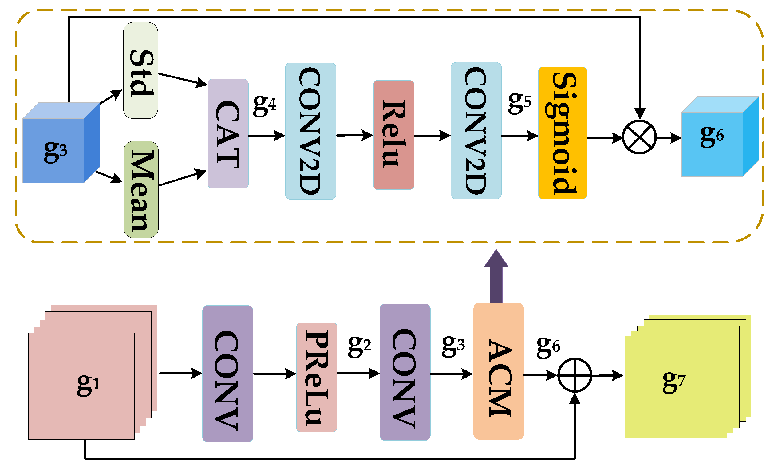
In SAR image processing tasks, we need a module to extract features while being able to calibrate them. Therefore, to preserve the feature mapping, the FCM is designed to acquire image information on multiple channels. The architecture of the FCM is shown in Figure 3, where g 1 R H × W × C and g 7 R H × W × C denote the input and output feature maps of the FCM. ACM denotes the Attention Correction Module which is the main component of the FCM.
First, we employ 1 × 1 CONV to perform the multi-channel transformation on g 1 , for characterizing as much image information as possible, as shown below:
g 2 = H P R e L u ( c o n v 1 × 1 ( g 1 , w 1 ) ) g 3 = c o n v 1 × 1 ( g 2 , w 2 ) ,
where c o n v 1 × 1 ( , w i ) indicates a convolution operation with kernel size of 1 and the weight w i . g 2 R H × W × C / 4 and g 3 R H × W × C represent the output feature maps after the corresponding CONV operations. H P R e L u ( ) denotes the PReLu activation function [42], which can adaptively correct the linear cell parameters.
ACM enhances the representation of feature maps, where g 3 and g 6 R H × W × C are the input and output of ACM, respectively. We first acquire the mean and standard deviation of g 3 , and then integrate them, as shown in the following equation:
g 4 = H c a t ( H s t d ( g 3 ) , H M e a n ( g 3 ) ) ,
where H s t d ( ) and H M e a n ( ) denote standard deviation pooling and mean pooling [43], respectively, and H c a t ( , ) denotes CAT. In addition, g 4 R 1 × 1 × C denotes the joint pooling feature. Afterward, two-dimensional CONV is employed for the multi-channel transformation of g 4 to produce g 5 R 1 × 1 × C , similar to Equation (6). After being activated by the Sigmoid function, g 5 interacts with g 3 to produce the attentional feature g 6 R H × W × C , As shown in the equation below:
g 6 = H S i g m o i d ( g 5 ) g 3 ,
where H S i g m o i d ( ) denotes the Sigmoid activation function and ⊗ denotes elements multiplication. Finally, we perform feature fusion between g 1 and g 6 to get the output of FCM g 7 R H × W × C ,
g 7 = g 6 g 1 ,
where ⊕ represents the elements addition.

3.2. MSN

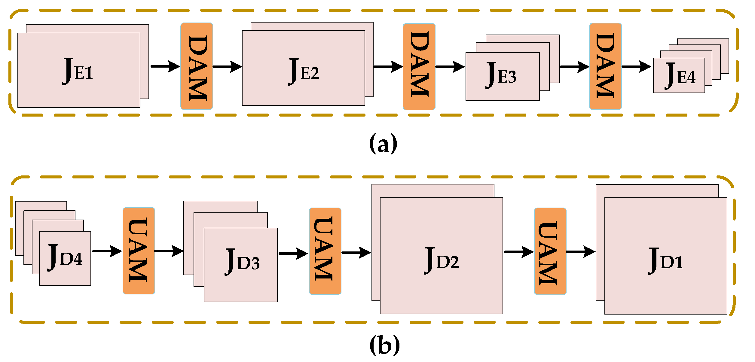
MSN considers the top encoder, bottom encoder, and decoder as the main structure, mainly used for removing interference features from the SAR image. The overall structure of MSN is shown in Figure 2. To reduce the computation amount and remove RFI features more effectively, we divide the image into two parts for processing [44], I Y _ Top R H / 2 × W × 3 and I Y _ Bot R H / 2 × W × 3 , respectively. Figure 4 gives the construction of the top encoder, bottom encoder and decoder. where DAM stands for Downsampling Attention Module, which consists of multiple FCMs connected in series and bilinear downsampling module. Correspondingly, UAM stands for upsampling Attention Module, which consists of multiple FCMs connected in series and bilinear upsampling module. The encoder increases the number of channels while continuously compressing input feature maps in dimensions. J E 1 R H / 2 × W × C , J E 2 R H / 2 × W × C , J E 3 R H / 4 × W / 2 × ( C + C a ) , and J E 4 R H / 8 × W / 4 × ( C + 2 × C a ) are feature maps output by each stage of the encoder. The C a R above indicates a fixed increase in the number of channels. The decoder reduces the number of channels while squeezing the feature maps to the original dimension. Among them, J D 1 R H × W × C , J D 2 R H × W × C , J D 3 R H / 2 × W / 2 × ( C + C a ) , and J D 4 R H / 4 × W / 4 × ( C + 2 × C a ) are feature maps output by each stage of the decoder. This multi-dimensional transformation on the feature maps generates more contextual information to make the model learn better. In addition, the multi-dimensional and multi-channel squeeze means makes it easier to filter out interference features.
In Figure 2, the MEN framework, the red dashed line indicates the transfer feature stream. This is an attention protection mechanism that avoids useful information being lost during dimensional transformations. Referring to Figure 4, assume that the features of each stage of Top Encoder are J TE 1 , J TE 2 , J TE 3 , J TE 4 , and similarly, the features of each stage of Bot Encoder are J BE 1 , J BE 2 , J BE 3 , J BE 4 . In summary, the attention protection mechanism can be expressed by the following equations:
J Eni = H c a t ( J TEi , J BEi ) J Di 1 = H U A M ( H F C M ( H F C M ( J Eni ) ) + J Di ) ,
where J Eni denotes the combined output features of the encoder at the ith stage. H c a t ( , ) indicates concatenation operation, H U A M ( ) indicates upsampling attention module and H F C M ( ) indicates FCM.

3.3. ICN

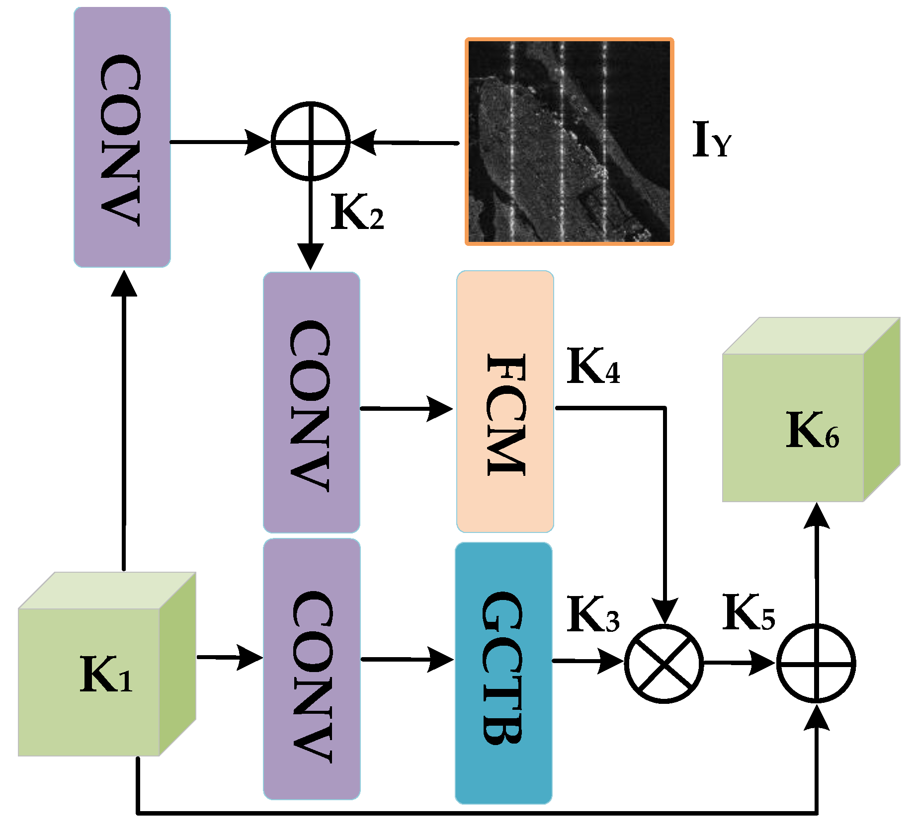
The MSN filters the interference features, however, the transformation of the dimension of the feature maps causes the loss of useful information and some discrepancies, so we design the ICN to calibrate the feature information. The overall structure of the ICN is shown in Figure 5, where K 1 R H × W × C and K 6 R H × W × C are the input and output of the ICN.
We first employ a 1×1 CONV on K 1 and perform feature fusion with I Y to generate K 2 R 512 × 512 × 3 , as shown in the following equation:
K 2 = c o n v 1 × 1 ( K 1 , w 3 ) + I Y .
Next, we adopt FCM to extract useful information from K 2 and generate K 4 R 512 × 512 × C with I Y features, as shown in the following equation:
K 4 = H F C M ( c o n v 1 × 1 ( K 2 , w 4 ) ) .
The gated channel transformation block (GCTB) [45] can comprehensively learn the relationships between channels and convey valid information, therefore we adopt the GCTB to collect channel information of K 1 , as shown in the following equation:
K 3 = H G C T B ( c o n v 1 × 1 ( K 1 , w 5 ) ) ,
where K 3 R 512 × 512 × C denotes the channel-wise feature and H G C T B ( ) denotes the GCTB response function. Afterward, we perform the attention interaction between K4 and K3 to produce K 5 R 512 × 512 × C . Finally, the feature fusion between K 5 and K 1 is performed to obtain K 6 R 512 × 512 × C , the above process as shown below:
K 5 = K 3 K 4 K 6 = K 1 K 5 .

3.4. RRM

RRM is designed to further profile the output feature maps from ICN and generate fine details for image restoration. Figure 6 gives the structure of the RRM and we can see that RRM is similar to a residual network. Where P 1 R H × W × C and I X R H × W × 3 are the input and output of the RRM. Additionally, the CEU represents the feature extraction unit, which is a series combination of the GCTB and FCM.
First, P1 goes through a series of CEUs to produce the abundant feature P 2 R H × W × C . Then, we perform the feature fusion between P2 and P1 to produce P 3 R H × W × C , as shown in the following equations:
P 2 = H C E U ( H C E U ( ( H C E U ( P 1 ) ) ) ) P 3 = P 1 P 2 ,
where H C E U ( ) denotes the CEU response function. After a 1 × 1 CONV on P 3 , the final ground recovery image I X is obtained under the supervision of I Y , the above as shown below:
I X = c o n v 1 × 1 ( P 3 , w 6 ) + I Y .

4. Experiments and Results

In this section, we will elaborate on the experiments in detail and display the final results. Firstly the dataset composition, the loss function, and the evaluation metrics will be presented. Secondly, compared with other state-of-the-art algorithms, the qualitative and quantitative results of the simulation data and measured Sentinel-1 data will be given.

4.1. Dataset

There is currently a lack of end-to-end data in the field of SAR jamming. Therefore based on Equation (4), we conduct relevant interference experiments to construct the simulation dataset. In addition, the Sentinel-1 satellite carries a C-band SAR, which provides continuous all-weather images. We take advantage of the periodicity of Sentine1 to construct the measured dataset. Typically, the interfered region is very small relative to the entire scene of the Sentinel-1. To reduce the computational effort and improve the processing efficiency of the method, we perform the cropping on Sentinel-1 images. In our experiments, we put 1600 pairs of simulated images and 400 pairs of measured images into one training sets X I = Iin I , Icl I , i = 1 , 2 , , 2000 , where Iin I and Icl I denote SAR images with interference and without interference.

4.2. Loss Function

Typically, the l 2 loss function causes the image to be too smooth which is not suitable for our task. To converge the training results and obtain fine images, we adopt Charbonnier Loss as the main item to approximate the l1 loss function for enhancing the performance of MCSNet. The entire loss function can be expressed by the following equation:
L S = C h a r ( I X , Icl ) + μ C h a r ( 2 ( I X ) , 2 ( Icl ) ) ,
where I X R 512 × 512 × 3 denotes the image predicted by MCSNet and Icl R 512 × 512 × 3 denotes the clean image. μ denotes the weight coefficient and L S denotes the value of the loss function. ( ) denote the gradients of the vectors. In addition, C h a r ( , ) denotes Charbonnier Loss and can be further expressed as:
C h a r ( A , B ) = ( A B ) 2 + ε ,
where A R H × W × C , B R H × W × C denote the tensor matrix. Additionally, ε denotes the penalty factor.

4.3. Assessment Indicators

To compare the quantitative results of the different methods, difference of Equivalent Noise of Looks ( Δ E N L ) [34,46], Structural Similarity ( S S I M ) [47], and Peak Signal to Noise Ratio (PSNR) [48] are selected as assessment indicators.
Typically, E N L is employed for grey-scale statistics of SAR images, as shown below:
I X = f ( a i , b j ) i = 0 , j = 0 H , W E N L = μ I X 2 σ I X 2 , μ I X = 1 H W i = 0 H j = 0 W f ( a i , b j ) , σ I X 2 = 1 H W i = 0 H j = 0 W ( f ( a i , b j ) μ I X ) 2 ,
where E N L indicates the value of Equivalent Noise of Looks. Additionally, μ I X and σ I X denote the mean and standard deviation of I X . In the field of SAR anti-interference, Δ E N L reflects the closeness between the image after interference suppression and the clean image, which can be expressed by the following equation:
Δ E N L = E N L _ I X E N L _ I c l ,
among them, E N L _ I X and E N L _ I c l denote the ENL values for I X and Icl . As explained above, a lower Δ E N L value indicates better interference suppression performance.
We employ SSIM to measure the similarity between SAR images, as shown below:
S S I M ( Icl , y ) = ( 2 μ x μ y + α 1 ) · ( 2 σ x y + α 2 ) ( μ x 2 + μ y 2 + α 1 ) · ( σ x 2 + σ y 2 + α 2 ) , α 1 = ( K 1 L ) 2 , α 2 = ( K 2 L ) 2 ,
where Icl R H × W × 3 denotes the clean image and y R H × W × 3 denotes the image to be measured. μ x and μ y denote the pixel averages of Icl and y . σ x 2 and σ y 2 denote the pixel variances of Icl and y . Moreover, σ x y denotes the correlation coefficient between Icl and y . Additionally, K 1 and K 1 default to 0.01 and 0.03, respectively, here L denotes the pixel range of the SAR image.
PSNR is a widely used objective method for assessing the quality of SAR images, As illustrated below:
P S N R ( Icl , y ) = 20 · log 10 ( M A X y M S E ( Icl , y ) ) ,
where M A X y denotes the maximum pixel value of y and M S E ( Icl , y ) denotes the mean squared error between Icl and y . Typically, higher PSNR and SSIM values can induce better image quality.

4.4. Simulation Data Results

We initially verify the effectiveness of the proposed method using simulation data. The simulation data mainly consists of three types of interference [49], namely squelching interference (SI), multipoint frequency shifting interference (MFSI), and RFI. The implementation of RFI has been mentioned in Equations (2) and (3). Furthermore, the principle of MFSI is to generate a range-oriented delay after SAR matching filtering, which can be expressed by the following equation:
MFSI ( f ) = S X · e j 2 π f d t f + ϕ f , f = 1 , 2 , , R ,
where f d denotes the amount of frequency shift. In addition, ϕ f denotes the random phase, which serves to make the phase between each pulse incoherent and thus produce line-like interference. In addition, the principle of SI is based on MFSI with increasing amount of frequency shift in synthetic aperture time, as follows:
F S D = Q · f b d ,
where Q denotes a positive integer, which varies with azimuth to time. In addition, f b d denotes fixed frequency shift increment, and F S D denotes total amount of frequency shift. To show the superiority of MCSNet, we adopt the excellent denoising algorithms in the visual field to compare with MSCNet, which are RESCAn [32] and SPANet [33], respectively, commonly used in tasks such as de-raining, de-fogging, and de-blurring.

4.4.1. Visual Results

The visual results of the simulation data are shown in Figure 7. Both the input-interfered images and the clean images without interference are simulated. The first column shows the input-interfered images, where (a) indicates SI, (b) indicates MFSI, and (c) indicates RFI. Additionally, the second column indicates the corresponding clean images without interference, and the third to fifth columns indicate the results for each method. The overall performance of SPANet [32] is not satisfactory, with many interference residual textures remaining on the results. RESCAn [33] performs well on (a) and (c), but for (b), the interference features are not completely removed. The results of our method are visually as expected and are all close to the clean image.

4.4.2. Closeness between Results and Clean Images

The naked eye observations are not sufficient to demonstrate the best performance of our method. Therefore, based on Equation (20), we adopt Δ ENL to check the ability of each method to maintain the scattering characteristics of SAR images. The corresponding results are given in Table 1, from which it can be seen that for (a), (b), and (c), our method achieves the lowest Δ ENL values.

4.4.3. Image Quality

Here, SSIM and PSNR are employed as metrics to evaluate the image quality of the simulation data (Table 2). Our methods both achieve the highest PSNR and SSIM values, whereas for (a), our results hold a PSNR value of 30.0051 and an SSIM value of 0.9962 much higher than the other methods. In short, for simulation data, MCSNet can suppress RFI while yielding high-resolution SAR images.

4.5. Measured Data Results

Our measured data are from the European Space Agency Sentinel-1A satellite in c-band. The data exist in the form of Ground Range Detected (GRD) type, with polarization modes as VV or VH. In general, the form of the GRD data mainly contains real-value amplitude information, reflecting the scattering intensity in the region. For the various forms of RFI on SAR images and different landscapes, several typical cases have been selected as measured data to analyse the qualitative and quantitative results. The geographical locations of these measured data are presented in Figure 8, where the red box indicates the area from which the interfered SAR images come.

4.5.1. Visual Results

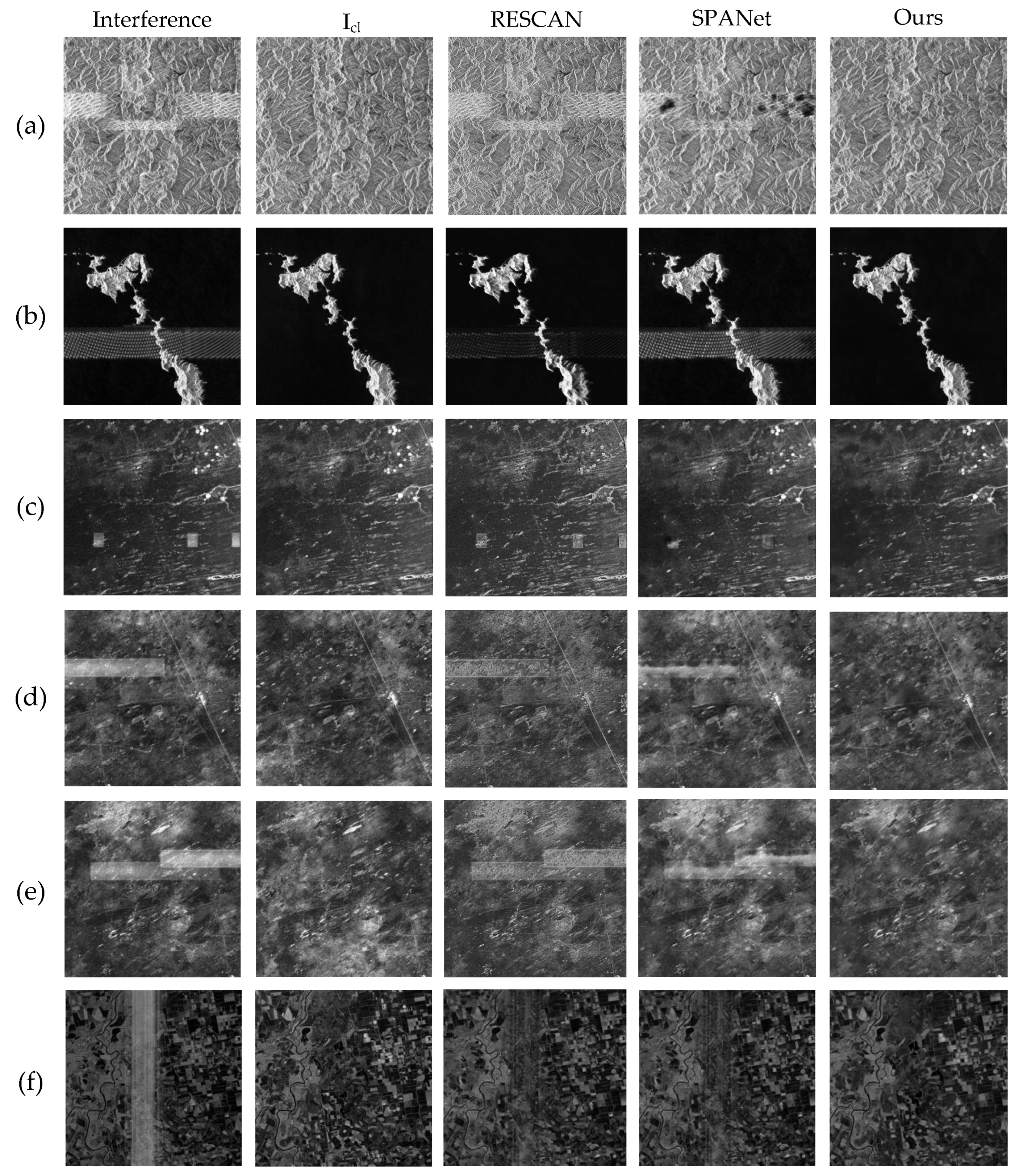
The visual results of the evaluation images are given in Figure 9, where the first column indicates the input-interfered images. The second column indicates the corresponding images without interference, they are clean images acquired at the same place at different times according to the periodicity of the Sentinel-1A. The third and fourth columns indicate the results of RESCAN and SPANet. The last column indicates the results of MCSNet. For (a) corresponds to Figure 8(I), this is acquired by Sentinel-1 on the Korean Peninsula on 29 March 2021, from which we can see a clear white ripple-like interference on the hilly terrain. For (b) corresponds to Figure 8(II), this is obtained by Sentinel-1 on 12 February 2022, in Nagasaki, Japan, from which it can be observed that the white striped RFI spans across the island and the sea, causing some visual obstruction. For (c) (d) and (e) corresponds to (III) in Figure 8, they are acquired by Sentinel-1 on 5 September 2021, in the Astrakhan region of Russia, from which it can be noticed that white block-like and stripe-like RFIs overlay the area in the images, causing some geographical features to become blurred. For (f) corresponds to Figure 8(IV), which is acquired by Sentinel-1 on 10 July 2021, in the Russian Volga estuary region, where high-power RFI covers a large area making the geographic information invisible. The results of RESCAN are not satisfactory, for (a), (b), (c), (d), (e), and (f), all of which have RFI features left on the images. The results of SCANet are also unsatisfactory, unable to find the RFI and remove it completely. In contrast, MCSNet is effective in suppressing interference on each image, and our results are visually close to clean images, reflecting the adaptability of MCSNet to different landscapes and different forms of RFI.
Figure 9. Visual results of measured data. The first column gives the interfered SAR images and the second column gives the corresponding ground truth. The third to fifth columns give the results of the different methods. Additionally, (af) indicate the different scenes from Figure 8. In addition, (a,c) the enlarged regions of interest are shown in Figure 10 and Figure 11.
Remotesensing 14 06337 g009
Figure 10. The region of interest for enlarged display in (a) of Figure 9.
Remotesensing 14 06337 g010
Figure 11. The region of interest for enlarged display in (c) of Figure 9.
Remotesensing 14 06337 g011

4.5.2. Closeness between Results and Clean Images

Qualitative results from visual observations are not sufficient to judge the merits of the methods, therefore we further compared the measured data quantitatively. As mentioned above, Δ E N L measures the closeness between the images after interference suppression and the clean images. The comparison results of Δ E N L are given in Table 3. For (a), (b), (c), (d), (e), and (f), our method achieves the lowest Δ E N L values, wherein (b) even reaches 0.0024, indicating that the results of MCSNet are closest to the clean images and the scattering characteristics of the original image are preserved.

4.5.3. Image Quality

The convolution and scaling operations in the network will inevitably cause some distortion to the image. Therefore, we adopt SSIM and PSNR as criteria to evaluate the image quality of each method. The clean images are taken as reference images and the corresponding results are given in Table 4. It can be observed that for each scene, our method achieves the highest PSNR and SSIM. In particular, for (b), MCSNet reaches 30.9641 PSNR value and 0.9896 SSIM value, which is much higher than the other methods. The overall results reflect that our method can conserve the useful information and details of the original image.

4.5.4. Comparisons of Scattering Characteristics

Typically, the grayscale statistics of SAR images reflect the intensity of scattering coefficients of ground objects [50]. The two images own similar gray-value magnitudes indicating that their scattering intensities are similar. The results of the scattering characteristics comparisons are shown in Figure 12. To concretely exhibit the capability of each method for preserving the scattering characteristics, we select (a), and (b) in Figure 9 as the test data. In addition, in Figure 12, the orange horizontal lines indicate the selected gray-value profiles. Where the trajectories of the blue and red curves are approximately fitted, indicating that our results have similar scattering properties to the clean images, with the best performance achieved.

5. Conclusions

To address the observational impact caused by multiple forms of RFI in Spaceborne SAR radar operation, this paper proposes a highly adaptive Multi-dimensional Calibration and Suppression Network (MCSNet) to solve this problem, which can only deal with real-valued data. Through analyzing the SAR image model, the input image is split into two parts for processing. First, the FCM is designed to capture full-text information. In addition, the Multidimensional Suppression Network is designed to suppress RFI at multi-channel and multi-scale levels. Next, a valid method is proposed to apply the input image as a reference image to correct the features in the network and preserve the valid information. Finally, a residual module with a channel attention mechanism is proposed to restore fine image details further yielding high-resolution images without RFI. Both the simulation data and measured data collected by Sentinel-1 verify the effectiveness of the proposed method. In comparison with state-of-the-art denoising methods in the field of computer vision, our method achieves the best results both qualitatively and quantitatively, indicating the specific functionality of our method for RFI suppression in Spaceborne SAR.

6. Discussion

For SAR images with real-valued information, our method indeed makes a difference. However, in the face of interference features completely overwhelming the whole image, the problem needs to be dealt with by adopting the complex-valued information of the SAR echo data and imaging results. Therefore, to make this idea of interference suppression more widely applicable, in future research we consider the design of networks that can handle complex-valued information.

Author Contributions

Conceptualization, H.Z. and X.L.; methodology, X.L. and H.Z.; software, H.Z. and J.R.; validation, X.L. and H.Z.; formal analysis, J.R. and X.L.; investigation, H.Z.; resources, S.W.; data curation, J.R.; writing—original draft preparation, H.Z.; writing—review and editing, H.Z.; visualization, H.Z. and S.W.; supervision, X.L.; project administration, X.L.; funding acquisition, X.L. All authors have read and agreed to the published version of the manuscript.

Funding

This research was funded by the National Natural Science Foundation of China under Grant 62271108.

Data Availability Statement

Not applicable.

Acknowledgments

The authors would like to thank the anonymous reviewers and editors for their selfless help to improve our manuscript.

Conflicts of Interest

The authors declare no conflict of interest.

References

  1. Zhou, Z.; Wei, S.; Zhang, H.; Shen, R.; Wang, M.; Shi, J.; Zhang, X. SAF-3DNet: Unsupervised AMP-Inspired Network for 3-D MMW SAR Imaging and Autofocusing. IEEE Trans. Geosci. Remote Sens. 2022, 60, 5234915. [Google Scholar] [CrossRef]
  2. Wei, S.; Zeng, X.; Zhang, H.; Zhou, Z.; Shi, J.; Zhang, X. LFG-Net: Low-Level Feature Guided Network for Precise Ship Instance Segmentation in SAR Images. IEEE Trans. Geosci. Remote Sens. 2022, 60, 5231017. [Google Scholar] [CrossRef]
  3. Lao, D.; Zhu, B.; Yu, S.; Guo, Y. An Improved SAR Imaging Algorithm Based on a Two-Dimension-Separated Algorithm. In Proceedings of the 2018 China International SAR Symposium (CISS), Shanghai, China, 10–12 October 2018; pp. 1–3. [Google Scholar] [CrossRef]
  4. Zeng, X.; Wei, S.; Shi, J.; Zhang, X. A Lightweight Adaptive RoI Extraction Network for Precise Aerial Image Instance Segmentation. IEEE Trans. Instrum. Meas. 2021, 70, 5018617. [Google Scholar] [CrossRef]
  5. Liu, G.; Liu, B.; Zheng, G.; Li, X. Environment Monitoring of Shanghai Nanhui Intertidal Zone with Dual-Polarimetric SAR Data Based on Deep Learning. IEEE Trans. Geosci. Remote Sens. 2022, 60, 4208918. [Google Scholar] [CrossRef]
  6. AlAli, Z.T.; Alabady, S.A. A survey of disaster management and SAR operations using sensors and supporting techniques. Int. J. Disaster Risk Reduct. 2022, 82, 103295. [Google Scholar] [CrossRef]
  7. Salvia, M.; Franco, M.; Grings, F.; Perna, P.; Martino, R.; Karszenbaum, H.; Ferrazzoli, P. Estimating Flow Resistance of Wetlands Using SAR Images and Interaction Models. Remote Sens. 2009, 1, 992–1008. [Google Scholar] [CrossRef] [Green Version]
  8. Li, N.; Lv, Z.; Guo, Z. Observation and Mitigation of Mutual RFI Between SAR Satellites: A Case Study Between Chinese GaoFen-3 and European Sentinel-1A. IEEE Trans. Geosci. Remote Sens. 2022, 60, 5112819. [Google Scholar] [CrossRef]
  9. Xu, W.; Xing, W.; Fang, C.; Huang, P.; Tan, W. RFI Suppression Based on Linear Prediction in Synthetic Aperture Radar Data. IEEE Geosci. Remote Sens. Lett. 2021, 18, 2127–2131. [Google Scholar] [CrossRef]
  10. Chen, Z.; Zhou, S.; Wang, X.; Huang, Y.; Wan, J.; Li, D.; Tan, X. Single Range Data-Based Clutter Suppression Method for Multichannel SAR. IEEE Geosci. Remote Sens. Lett. 2022, 19, 4012905. [Google Scholar] [CrossRef]
  11. Li, N.; Zhang, H.; Lv, Z.; Min, L.; Guo, Z. Simultaneous Screening and Detection of RFI From Massive SAR Images: A Case Study on European Sentinel-1. IEEE Trans. Geosci. Remote Sens. 2022, 60, 5231917. [Google Scholar] [CrossRef]
  12. Wei, S.; Zhang, H.; Zeng, X.; Zhou, Z.; Shi, J.; Zhang, X. CARNet: An effective method for SAR image interference suppression. Int. J. Appl. Earth Obs. Geoinf. 2022, 114, 103019. [Google Scholar] [CrossRef]
  13. Tang, Z.; Deng, Y.; Zheng, H. RFI Suppression for SAR via a Dictionary-Based Nonconvex Low-Rank Minimization Framework and Its Adaptive Implementation. Remote Sens. 2022, 14, 678. [Google Scholar] [CrossRef]
  14. Lord, R.T.; Inggs, M.R. Efficient RFI suppression in SAR using LMS adaptive filter integrated with range/Doppler algorithm. Electron. Lett. IEE 1999, 35, 629. [Google Scholar] [CrossRef]
  15. Li, N.; Lv, Z.; Guo, Z.; Zhao, J. Time-Domain Notch Filtering Method for Pulse RFI Mitigation in Synthetic Aperture Radar. IEEE Geosci. Remote Sens. Lett. 2022, 19, 4013805. [Google Scholar] [CrossRef]
  16. Zhou, F.; Wu, R.; Xing, M.; Bao, Z. Eigensubspace-Based Filtering with Application in Narrow-Band Interference Suppression for SAR. IEEE Geosci. Remote Sens. Lett. 2007, 4, 75–79. [Google Scholar] [CrossRef]
  17. Chang, W.; Li, J.; Li, X. The Effect of Notch Filter on RFI Suppression. Wirel. Sens. Netw. 2009, 1, 196–205. [Google Scholar] [CrossRef]
  18. Wu, P.; Yang, L.; Zhang, Y.S.; Dong, Z.; Wang, M.; Du, S. A modified notch filter for suppressing radio-frequency-interference in P-band SAR data. In Proceedings of the 2016 IEEE International Geoscience and Remote Sensing Symposium (IGARSS), Beijing, China, 10–15 July 2016; pp. 4988–4991. [Google Scholar] [CrossRef]
  19. Xu, W.; Xing, W.; Fang, C.; Huang, P.; Tan, W.; Gao, Z. RFI Suppression for SAR Systems Based on Removed Spectrum Iterative Adaptive Approach. Remote Sens. 2020, 12, 3520. [Google Scholar] [CrossRef]
  20. Feng, J.; Zheng, H.; Deng, Y.; Gao, D. Application of Subband Spectral Cancellation for SAR Narrow-Band Interference Suppression. IEEE Geosci. Remote Sens. Lett. 2012, 9, 190–193. [Google Scholar] [CrossRef]
  21. Liu, H.; Li, D.; Zhou, Y.; Truong, T.K. Joint Wideband Interference Suppression and SAR Signal Recovery Based on Sparse Representations. IEEE Geosci. Remote Sens. Lett. 2017, 14, 1542–1546. [Google Scholar] [CrossRef]
  22. Lyu, Q.; Han, B.; Li, G.; Sun, W.; Pan, Z.; Hong, W.; Hu, Y. SAR Interference Suppression Algorithm Based on Low-Rank and Sparse Matrix Decomposition in Time–Frequency Domain. IEEE Geosci. Remote Sens. Lett. 2022, 19, 4008305. [Google Scholar] [CrossRef]
  23. Huang, Y.; Liao, G.; Zhang, Z.; Xiang, Y.; Li, J.; Nehorai, A. Fast Narrowband RFI Suppression Algorithms for SAR Systems via Matrix-Factorization Techniques. IEEE Trans. Geosci. Remote Sens. 2019, 57, 250–262. [Google Scholar] [CrossRef]
  24. Yang, H.; Chen, C.; Chen, S.; Xi, F.; Liu, Z. SAR RFI Suppression for Extended Scene Using Interferometric Data via Joint Low-Rank and Sparse Optimization. IEEE Geosci. Remote Sens. Lett. 2021, 18, 1976–1980. [Google Scholar] [CrossRef]
  25. Fang, J.; Hu, S.; Ma, X. A Boosting SAR Image Despeckling Method Based on Non-Local Weighted Group Low-Rank Representation. Sensors 2018, 18, 3448. [Google Scholar] [CrossRef] [PubMed] [Green Version]
  26. Zhou, F.; Xing, M.; Bai, X.; Sun, G.; Bao, Z. Narrow-Band Interference Suppression for SAR Based on Complex Empirical Mode Decomposition. IEEE Geosci. Remote Sens. Lett. 2009, 6, 423–427. [Google Scholar] [CrossRef]
  27. Lu, X.; Su, W.; Yang, J.; Gu, H.; Zhang, H.; Yu, W.; Yeo, T.S. Radio Frequency Interference Suppression for SAR via Block Sparse Bayesian Learning. IEEE J. Sel. Top. Appl. Earth Obs. Remote Sens. 2018, 11, 4835–4847. [Google Scholar] [CrossRef]
  28. Liu, H.; Li, D. RFI Suppression Based on Sparse Frequency Estimation for SAR Imaging. IEEE Geosci. Remote Sens. Lett. 2016, 13, 63–67. [Google Scholar] [CrossRef]
  29. Wang, M.; Wei, S.; Zhou, Z.; Shi, J.; Zhang, X. Efficient ADMM Framework Based on Functional Measurement Model for mmW 3-D SAR Imaging. IEEE Trans. Geosci. Remote Sens. 2022, 60, 5226417. [Google Scholar] [CrossRef]
  30. Fan, W.; Zhou, F.; Tao, M.; Bai, X.; Rong, P.; Yang, S.; Tian, T. Interference Mitigation for Synthetic Aperture Radar Based on Deep Residual Network. Remote Sens. 2019, 11, 1654. [Google Scholar] [CrossRef]
  31. Shen, J.; Han, B.; Pan, Z.; Hu, Y.; Hong, W.; Ding, C. Radio Frequency Interference Suppression in SAR System Using Prior-Induced Deep Neural Network. In Proceedings of the IGARSS 2022—2022 IEEE International Geoscience and Remote Sensing Symposium, Kuala Lumpur, Malaysia, 4–7 November 2022; pp. 943–946. [Google Scholar] [CrossRef]
  32. Li, X.; Wu, J.; Lin, Z.; Liu, H.; Zha, H. Recurrent squeeze-and-excitation context aggregation net for single image deraining. In Proceedings of the European Conference on Computer Vision (ECCV), Munich, Germany, 8–14 September 2018; pp. 254–269. [Google Scholar]
  33. Wang, T.; Yang, X.; Xu, K.; Chen, S.; Zhang, Q.; Lau, R.W. Spatial attentive single-image deraining with a high quality real rain dataset. In Proceedings of the IEEE/CVF Conference on Computer Vision and Pattern Recognition, Long Beach, CA, USA, 15–20 June 2019; pp. 12270–12279. [Google Scholar]
  34. Liu, Z.; Lai, R.; Guan, J. Spatial and Transform Domain CNN for SAR Image Despeckling. IEEE Geosci. Remote Sens. Lett. 2022, 19, 4002005. [Google Scholar] [CrossRef]
  35. Xiong, K.; Zhao, G.; Wang, Y.; Shi, G.; Chen, S. Lq-SPB-Net: A Real-Time Deep Network for SAR Imaging and Despeckling. IEEE Trans. Geosci. Remote Sens. 2022, 60, 5209721. [Google Scholar] [CrossRef]
  36. Su, J.; Tao, H.; Tao, M.; Wang, L.; Xie, J. Narrow-Band Interference Suppression via RPCA-Based Signal Separation in Time–Frequency Domain. IEEE J. Sel. Top. Appl. Earth Obs. Remote Sens. 2017, 10, 5016–5025. [Google Scholar] [CrossRef]
  37. Tao, M.; Su, J.; Huang, Y.; Wang, L. Mitigation of Radio Frequency Interference in Synthetic Aperture Radar Data: Current Status and Future Trends. Remote Sens. 2019, 11, 2438. [Google Scholar] [CrossRef] [Green Version]
  38. Xu, G.; Zhang, B.; Yu, H.; Chen, J.; Xing, M.; Hong, W. Sparse Synthetic Aperture Radar Imaging From Compressed Sensing and Machine Learning: Theories, applications, and trends. IEEE Geosci. Remote Sens. Mag. 2022, 12, 2–40. [Google Scholar] [CrossRef]
  39. Wang, M.; Wei, S.; Zhou, Z.; Shi, J.; Zhang, X.; Guo, Y. CTV-Net: Complex-Valued TV-Driven Network with Nested Topology for 3-D SAR Imaging. IEEE Trans. Neural Netw. Learn. Syst. 2022, 1–15. [Google Scholar] [CrossRef]
  40. Wang, M.; Wei, S.; Zhou, Z.; Shi, J.; Zhang, X.; Guo, Y. 3-D SAR Data-Driven Imaging via Learned Low-Rank and Sparse Priors. IEEE Trans. Geosci. Remote Sens. 2022, 60, 1–17. [Google Scholar] [CrossRef]
  41. Luo, X.; Chang, X.; Ban, X. Regression and classification using extreme learning machine based on L1-norm and L2-norm. Neurocomputing 2016, 174, 179–186. [Google Scholar] [CrossRef]
  42. He, K.; Zhang, X.; Ren, S.; Sun, J. Delving deep into rectifiers: Surpassing human-level performance on imagenet classification. In Proceedings of the IEEE International Conference on Computer Vision, Santiago, Chile, 7–13 December 2015; pp. 1026–1034. [Google Scholar]
  43. Hsiao, T.Y.; Chang, Y.C.; Chou, H.H.; Chiu, C.T. Filter-based deep-compression with global average pooling for convolutional networks. J. Syst. Archit. 2019, 95, 9–18. [Google Scholar] [CrossRef]
  44. Zamir, S.W.; Arora, A.; Khan, S.; Hayat, M.; Khan, F.S.; Yang, M.H.; Shao, L. Multi-stage progressive image restoration. In Proceedings of the IEEE/CVF Conference on Computer Vision and Pattern Recognition, Nashville, TN, USA, 20–25 June 2021; pp. 14821–14831. [Google Scholar]
  45. Yang, Z.; Zhu, L.; Wu, Y.; Yang, Y. Gated Channel Transformation for Visual Recognition. In Proceedings of the IEEE/CVF Conference on Computer Vision and Pattern Recognition (CVPR), Seattle, WA, USA, 13–19 June 2020. [Google Scholar]
  46. Lee, J.S. A simple speckle smoothing algorithm for synthetic aperture radar images. IEEE Trans. Syst. Man Cybern. 1983, SMC-13, 85–89. [Google Scholar] [CrossRef]
  47. Sara, U.; Akter, M.; Uddin, M.S. Image quality assessment through FSIM, SSIM, MSE and PSNR—A comparative study. J. Comput. Commun. 2019, 7, 8–18. [Google Scholar] [CrossRef] [Green Version]
  48. Hore, A.; Ziou, D. Image quality metrics: PSNR vs. SSIM. In Proceedings of the 2010 20th International Conference on Pattern Recognition, Istanbul, Turkey, 23–26 August 2010; pp. 2366–2369. [Google Scholar]
  49. Zhou, F.; Zhao, B.; Tao, M.; Bai, X.; Chen, B.; Sun, G. A Large Scene Deceptive Jamming Method for Space-Borne SAR. IEEE Trans. Geosci. Remote Sens. 2013, 51, 4486–4495. [Google Scholar] [CrossRef]
  50. Lingyan, C.; Zhi, L.; Hong, Z. SAR image water extraction based on scattering characteristics. Remote Sens. Technol. Appl. 2015, 29, 963–969. [Google Scholar]
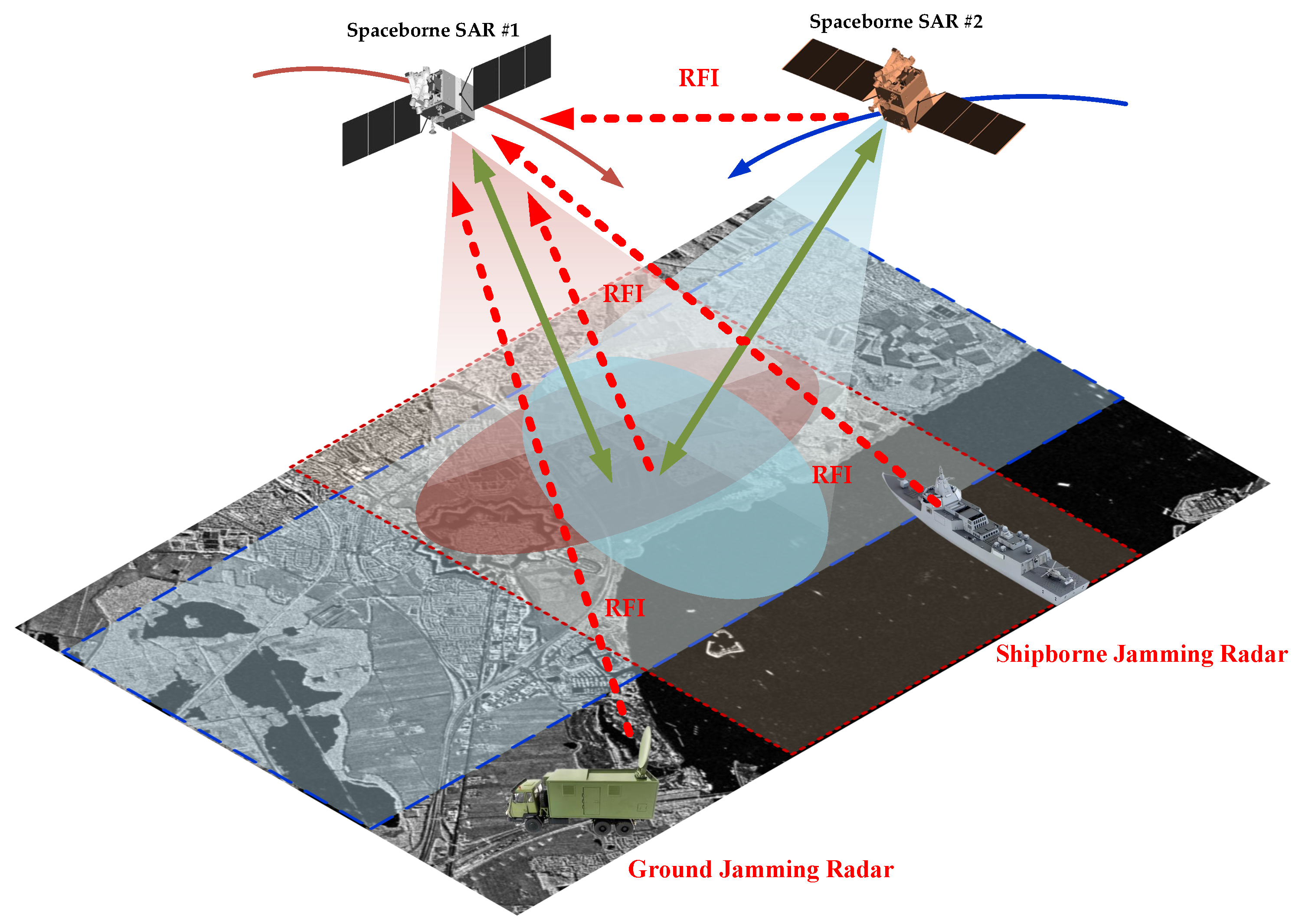
Figure 1. Geometric interpretation of interference to Spaceborne SAR.
Remotesensing 14 06337 g001
Figure 2. The overall structure of Multi-dimensional Calibration and Suppression Network, referred to as MCSNet. Where I Y and I X denote the input image with interference and the output result of MCSNet, respectively. The black arrows indicate the transfer information stream and the red dashed lines indicate the transfer feature stream. CONV and CAT denote convolution and concatenation operations, respectively.
Remotesensing 14 06337 g002
Figure 3. The overall structure of FCM, referred to as FCM. Where the black arrows indicate the transfer information stream. ⊕ and ⊗ denote feature fusion and elements multiplication, respectively.
Remotesensing 14 06337 g003
Figure 4. The overall structure of the top encoder, bottom encoder and decoder. Where (a) is the structure of top encoder and bottom encoder. In addition, (b) is the structure of decoder. The black arrows indicate the transfer information stream. DAM indicates Downsampling Attention Module, UAM indicates Upsampling Attention Module.
Remotesensing 14 06337 g004
Figure 5. The overall structure of ICN. Where the black arrows indicate the transfer information stream. ⊕ and ⊗ denote feature fusion and elements multiplication, respectively.
Remotesensing 14 06337 g005
Figure 6. The overall structure of RRM. Where the black arrows indicate the transfer information stream and ⊕ denotes feature fusion.
Remotesensing 14 06337 g006
Figure 7. Visual results of simulation data. The first column gives the interfered SAR images and the second column gives the corresponding ground truth. The third to fifth columns give the results of the different methods. In addition, (ac) indicate the different types of interference.
Remotesensing 14 06337 g007
Figure 8. Geographical location description for measured data, where (I) in the region of the Korean Peninsula, (II) in the sea and islands off Nagasaki, Japan, (III) in Astrakhan, Russia, and (IV) in Krasnodar Krai, Russia. The red box indicates the interfered area, with a unit length of 100 km.
Remotesensing 14 06337 g008
Figure 12. Scattering characteristics analysis. Where the orange horizontal line indicates the gray-value profile. The red curves indicate the scattering analysis of our results. The blue curves indicate the scattering analysis of the clean image.
Remotesensing 14 06337 g012
Table 1. Comparisons of Δ E N L for simulation data.
MethodInterferenceRESCANSPANetOurs
Scene
(a)0.04770.08650.02690.0231
(b)0.05040.14500.03020.0178
(c)38.85911.07191.72980.7506
Table 2. Comparisons of SSIM and PSNR for simulation data.
MethodInterferenceRESCANSPANetOurs
Scene PSNRSSIMPSNRSSIMPSNRSSIMPSNRSSIM
(a)19.30250.848329.95750.983620.18140.870830.00510.9962
(b)20.11160.778226.62440.937627.53430.948836.10400.9921
(c)6.76350.398222.48730.806210.99400.423922.77800.8159
Table 3. Comparisons of Δ E N L for measured data.
MethodInterferenceRESCANSPANetOurs
Scene
(a)1.07095.05891.2930.3561
(b)0.12380.02990.14650.0024
(c)1.14821.75340.54280.2512
(d)3.30514.32301.80001.2008
(e)1.46862.19992.16100.3544
(f)0.64562.50040.91920.2447
Table 4. Comparisons of SSIM and PSNR for measured data.
MethodInterferenceRESCANSPANetOurs
ScenePSNRSSIMPSNRSSIMPSNRSSIMPSNRSSIM
(a)19.24950.835520.05830.833620.32170.864423.00510.9189
(b)20.17410.865324.68360.953919.42710.840030.96410.9896
(c)21.28400.842022.96710.845323.66110.870523.77540.8796
(d)18.68940.617318.68940.658519.31250.676322.33890.7878
(e)16.55280.541118.08340.567017.33230.579719.85910.7148
(f)17.52520.525119.89130.639820.06420.694721.81890.8022
Publisher’s Note: MDPI stays neutral with regard to jurisdictional claims in published maps and institutional affiliations.