
The Prototype of a Fast Vertical Ionosonde Based on Modern Software-Defined Radio Devices

 ,
, 
Abstract
:1. Introduction
2. Materials and Methods
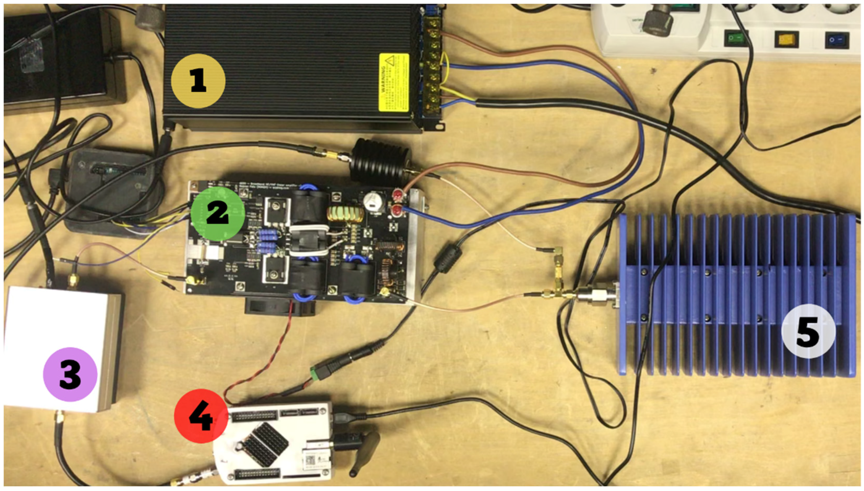
2.1. Hardware Part
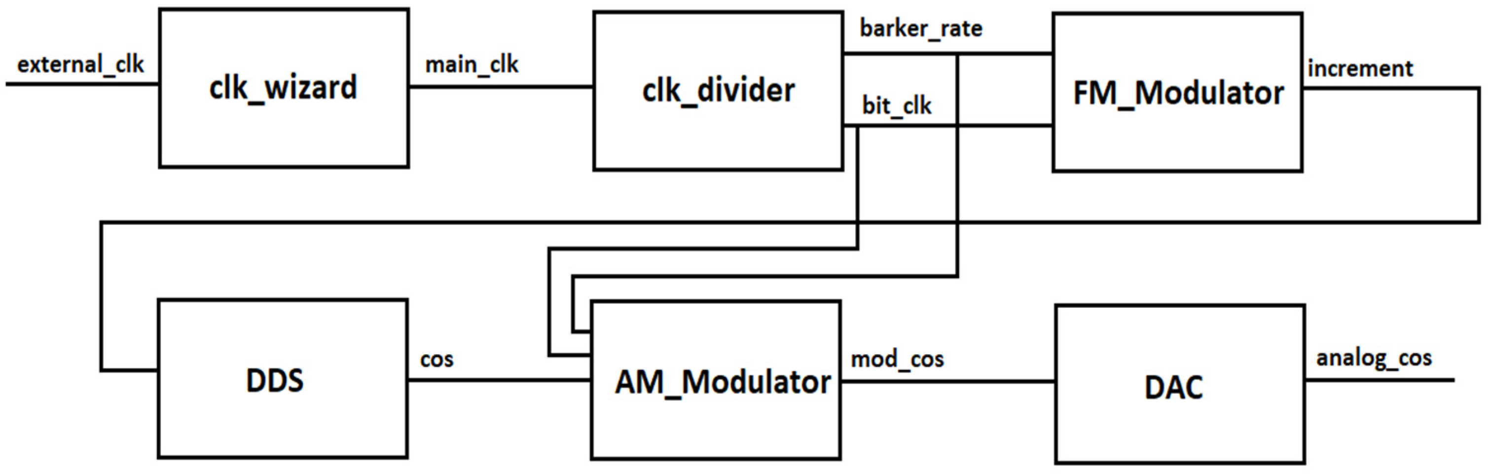
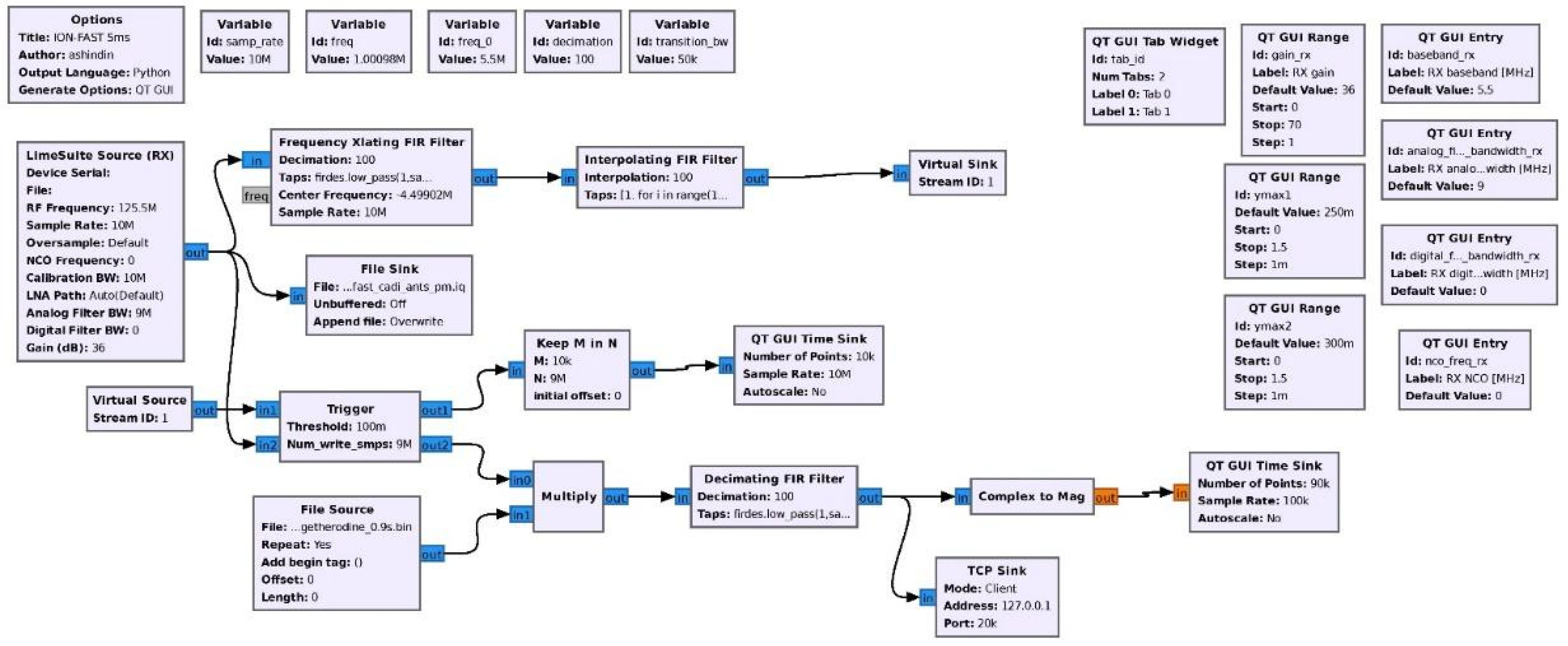
2.2. Software Part
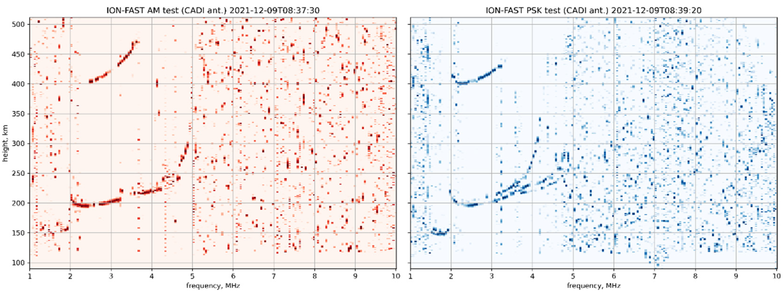
3. Test Results
4. Discussion
5. Conclusions
Supplementary Materials
Author Contributions
Funding
Institutional Review Board Statement
Informed Consent Statement
Data Availability Statement
Acknowledgments
Conflicts of Interest
References
- Yamamoto, M. Digital beacon receiver for ionospheric TEC measurement developed with GNU Radio. Earth Planet Space 2008, 60, e21–e24. [Google Scholar] [CrossRef] [Green Version]
- Vierinen, J. GNU Chirp Sounder. Available online: https://www.sgo.fi/~j/gnu_chirp_sounder/ (accessed on 21 December 2021).
- Ivanov, V.A.; Kurkin, V.I.; Nosov, V.E.; Uryadov, V.P.; Shumaev, V.V. Chirp ionosonde and its application in the ionospheric research. Radiophys. Quantum Electron. 2003, 46, 821–851. [Google Scholar] [CrossRef]
- Hunsucker, R.D. Radio Techniques for Probing the Terrestrial Ionosphere; Book Series Physics and Chemistry in Space 22 Planetology; Springer: Berlin/Heidelberg, Germany, 1991; pp. 65–93. [Google Scholar]
- Canadian High Arctic Ionospheric Network Cadi. Available online: http://chain.physics.unb.ca/chain/pages/cadi/ (accessed on 21 December 2021).
- CADI at Vasilsursk Site. Available online: https://ip-2-165.unn.ru:3389/cadi/ (accessed on 21 December 2021).
- A600—HF_6m 600W LDMOS Amplifier QRPblog. Available online: https://qrpblog.com/a600-hf-6m-600w-ldmos-amplifier/ (accessed on 21 December 2021).
- SDRlab 122-16—Red Pitaya 0.97 Documentation. Available online: https://redpitaya.readthedocs.io/en/latest/developerGuide/hardware/122-16/top.html (accessed on 21 December 2021).
- LimeSDR—Lime Microsystems. Available online: https://limemicro.com/products/boards/limesdr/ (accessed on 21 December 2021).
- GNU Radio—The Free & Open Source Radio Ecosystem · GNU Radio. Available online: https://www.gnuradio.org/ (accessed on 21 December 2021).
- NumPy. Available online: https://numpy.org/ (accessed on 21 December 2021).
- SciPy. Available online: https://scipy.org/ (accessed on 21 December 2021).
- Matplotlib—Visualization with Python. Available online: https://matplotlib.org/ (accessed on 21 December 2021).
- Open Broadcaster Software OBS. Available online: https://obsproject.com (accessed on 21 December 2021).
- Branitskii, A.V.; Kim, V.Y.; Polimatidi, V.P. Rapid Variations in Electron Density Profiles in the Ionosphere Detected with the Izmiran High-Speed Ionosonde. Geomagn. Aeron. 2020, 60, 63–79. [Google Scholar] [CrossRef]
- Vybornov, F.I.; Mityakova, E.E.; Rakhlin, A.V.; Krupenya, N.D. Analysis of appearance of moving ionospheric disturbances of the “sickle” type at middle latitudes. Radiophys. Quantum Electron. 1997, 40, 980–986. [Google Scholar] [CrossRef]
- Vertogradov, G.G.; Uryadov, V.P.; Vybornov, F.I.; Pershin, A.V. Modeling of Decameter Radio Wave Propagation Under Conditions of a WaveLike Electron-Density Disturbance. Radiophys. Quantum Electron. 2018, 61, 407–417. [Google Scholar] [CrossRef]
- Harris, T.J.; Cervera, M.A.; Meehan, D.H. SpICE: A program to study small-scale disturbances in the ionosphere. J. Geophys. Res. 2012, 117, A06321. [Google Scholar] [CrossRef] [Green Version]
- Kurkin, V.I.; Laryunin, O.A.; Podlesny, A.V.; Pezhemskaya, M.D.; Chistyakova, L.V. Studying morphological characteristics of traveling ionospheric disturbances with the use of near-vertical ionospheric sounding data. Atmos. Ocean. Opt. 2014, 27, 303–309. [Google Scholar] [CrossRef]
- Bakhmet’eva, N.V.; Belikovich, V.V.; Ignat’ev, Y.A.; Ponyatov, A.A. Vertical motions in the lower ionosphere and a sporadic E layer. Radiophys. Quantum Electron. 1999, 42, 22–30. [Google Scholar] [CrossRef]
- Frolov, V.L.; Bakhmet’eva, N.V.; Belikovich, V.V.; Vertogradov, G.G.; Vertogradov, V.G.; Komrakov, G.P.; Kotik, D.S.; Mityakov, N.A.; Polyakov, S.V.; Rapoport, V.O.; et al. Modification of the earth’s ionosphere by high-power high-frequency radio waves. Phys.-Uspekhi 2007, 50, 315–324. [Google Scholar] [CrossRef]


Publisher’s Note: MDPI stays neutral with regard to jurisdictional claims in published maps and institutional affiliations. |
© 2022 by the authors. Licensee MDPI, Basel, Switzerland. This article is an open access article distributed under the terms and conditions of the Creative Commons Attribution (CC BY) license (https://creativecommons.org/licenses/by/4.0/).
Share and Cite
Shindin, A.V.; Moiseev, S.P.; Vybornov, F.I.; Grechneva, K.K.; Pavlova, V.A.; Khashev, V.R. The Prototype of a Fast Vertical Ionosonde Based on Modern Software-Defined Radio Devices. Remote Sens. 2022, 14, 547. https://doi.org/10.3390/rs14030547
Shindin AV, Moiseev SP, Vybornov FI, Grechneva KK, Pavlova VA, Khashev VR. The Prototype of a Fast Vertical Ionosonde Based on Modern Software-Defined Radio Devices. Remote Sensing. 2022; 14(3):547. https://doi.org/10.3390/rs14030547
Chicago/Turabian StyleShindin, Alexei V., Sergey P. Moiseev, Fedor I. Vybornov, Kseniya K. Grechneva, Viktoriya A. Pavlova, and Vladimir R. Khashev. 2022. "The Prototype of a Fast Vertical Ionosonde Based on Modern Software-Defined Radio Devices" Remote Sensing 14, no. 3: 547. https://doi.org/10.3390/rs14030547