Article

Frequency-Domain Electromagnetic Mapping of an Abandoned Waste Disposal Site: A Case in Sardinia (Italy)

1
Department of Civil and Environmental Engineering and Architecture, University of Cagliari, via Marengo 2, 09123 Cagliari, Italy
2
Department of Petrology, Geochemistry, and Geological Prospection, Universitat de Barcelona, Martí y Franquès s/n, 08030 Barcelona, Spain
3
Department of Geosciences, University of Padua, via Gradenigo 6, 35131 Padua, Italy
*
Author to whom correspondence should be addressed.
Remote Sens. 2022, 14(4), 878; https://doi.org/10.3390/rs14040878
Submission received: 11 January 2022 / Revised: 9 February 2022 / Accepted: 10 February 2022 / Published: 12 February 2022

Abstract

:
For decades, bad practices in municipal and industrial waste management have had negative environmental impacts, generating high health risks for people and the environment. The use of badly designed, not engineered, and not well-operated landfills has, around the world, produced a large number of potentially contaminated sites, for which there are urgent needs to assess the actual risk and to proceed, in case, with reclamation activities. One of these sites, an abandoned waste disposal site located near a Site of Community Importance on the central-eastern coast of Sardinia (Italy), is the subject of the case history described in this work. As a part of a multi-method geophysical characterisation, a frequency-domain electromagnetic (FDEM) mapping survey was carried out with the specific aim of detecting the presence of buried materials (waste) and of delineating the lateral extent of the landfill by identifying the electrical conductivity anomalies produced, for the most part, by the conductive waste fill. Using an EM31 device in the vertical-dipole configuration, at a height of 0.9 m above the ground, both quadrature and in-phase electromagnetic responses were collected over a 7-hectare area with elevation varying between 6 m and 2.8 m above sea level. After removing the measurements identified as data coming from any recognisable surface man-made features within the survey area or near its perimeter, the filtered quadrature response (expressed as apparent conductivity) ranged from 5.5 mS/m to about 188.6 mS/m. All values are beyond the low induction number (LIN) condition and valid for the classical EM31 mapping, thus requiring advanced data processing. To obtain undistorted, meaningful, and interpretable high-resolution maps, measured data have been processed to correct the bias, introduced by the nonlinearity of the device, as a function of height above ground and the topography. The comparative analysis of the apparent conductivity map, obtained by the properly processed EM31 data and some aerial photos that clearly documented the site history, has allowed unequivocal delineation of the landfill extent, in good agreement with the results obtained with other geophysical methods (not described in this paper) and with the ground truthing data provided by three boreholes, which were core-drilled at the end of the study at three locations selected on the basis of the apparent conductivity map.

1. Introduction

In developed and industrialised countries, landfills for municipal and industrial solid waste disposal are, nowadays, well-designed, constructed, and operated so as to ensure minimal environmental impact in the surrounding areas. For many decades, however, and before the hazards associated with waste disposal were well understood, they have been neither designed, nor engineered, nor operated to meet the requirements for safe disposal of solid waste and to minimise the impact on the environment. Poor governmental management and/or lack of social and industrial organisation have been the reasons for the very large number of sites developed without any control on the selection of site, and the collection, transport, and final disposal of waste. The choice of landfill locations, which should be suggested by environmental, geologic, and engineering considerations, was usually dictated on the basis of convenience, proximity of waste source, and private business considerations.
To prevent or reduce health risks for the population and the environment related to the past bad practices in landfill management, the Council of the European Union has enacted stringent measures (Directive 1999/31/EC) [1] for landfill management, enforcing reclamation of all existent landfill areas in European countries. To implement these European instructions and guidelines, in 2003 the Sardinian Regional Government (“Regione Autonoma della Sardegna”) drew up a waste management plan (“Piano di Bonifica dei Siti Inquinati”), which also contained a list of priorities based on the risk assessment for the sites representing potential pollution. According to this plan, the number of illegal landfills in Sardinia was 404, of which 59 were considered dangerous and thus to be prioritised. One of these sites, the Bacàsara site, also known as the Bacchidda-Salinas site, is the site study of the present work. At the time, little documented information was available and the plan itself only reported some expected values about the landfill extension (69,800 m2), the thickness of the buried waste materials (7 m), and the total volume of fill (302,370 m3). However, due to the location of the site, critically near the Tortolì Pond, which is a surface water body considered a Site of Community Importance according to the Council Directive 92/43/EEC [2], and also due to the geological and hydrogeological conditions of the site, which have the potential to spread out possible contamination within the aquifer or to nearby surface waters, the landfill site was placed at the 4th position in the regional priority list. Thus, in the regional priority list, an urgent need for a detailed environmental characterisation was stressed to assess the actual risk associated with the landfill and to proceed, in case, with the subsequent remediation activities.
Keeping in mind that a good site characterisation is mandatory for effective remediation works, we started with a geophysical characterisation to supply fast, non-invasive, and yet detailed evaluations of the lateral and vertical extent of the impacted volume at the site. Geophysical investigations cannot totally replace drilling and sampling in environmental site characterisation, as they do not allow assessment of whether contaminants are present in soils and water above given concentrations defined by regulations. Yet, geophysical surveys represent a useful tool, as they help plan the drilling and sampling programs, cutting down the associated costs. Moreover, geophysical surveys provide high-resolution information with a much greater spatial coverage than boreholes, and ensure that no spatial aliasing is present in the maps of interpolated geophysical data. Aliasing occurs when the sampling frequency is inadequately low compared with the frequency of signal variation [3]. This can happen in any “direction”, be it time or space (or both). As a result of spatial aliasing, the sampled variable assumes smooth variations in space, with a spatial frequency that is much lower than the true one, thus appearing different from what the reality is (i.e., an alias). The impact of such aliasing on the assessment of the spatial patterns of the objective variable can be dramatic, typically resulting in the overestimation, e.g., of the contaminated volumes (e.g., [4]).
Two geophysical surveys were carried out using different geophysical methods (frequency-domain electromagnetics, electrical resistivity and induced polarisation tomographies, magnetometry, and refraction seismics) with the aim of (i) delineating the vertical extent, as well as the boundaries of the suspected area of the landfill; (ii) determining the potential presence of buried waste materials and leachate in the suspected area of the landfill; (iii) tentatively identifying the type of dumped materials; (iv) assessing possible interactions of the landfill with the nearby aquifer; and (v) characterising the encasing rocks. The first preliminary survey, which involved the frequency-domain electromagnetic induction (EMI) method as a mapping tool, is the focus of the present work.
EMI methods have been used extensively for near-surface characterisation [5,6,7,8,9,10], as the use of small-measurement systems with rapid responses allow dense surveying over large areas in a cost-effective manner. Recent multi-coil and/or multi-frequency devices, which are able to record multi-depth electromagnetic complex-valued responses, are increasingly used to obtain quantitative interpretation of EMI data by linear inversion, when soil properties (electrical conductivity and magnetic permeability) and device parameters (working frequency and inter-coil separation) combine in a low induction number (LIN) condition [11,12,13,14,15], or, otherwise, by nonlinear inversion in the cases of high-conductivity terrain, where the LIN approximation breaks down [5,16,17,18].
In the past, the most widespread traditional EMI devices, such as, for example, the Geonics EM38 and EM31, were mostly used as instruments for apparent electrical conductivity mapping, as they were designed to record a single depth response, usually associated with a conventional depth of penetration. Actually, they can also be used to perform sounding surveys to get quantitative estimates of depth variations in true electrical conductivity [19,20], but with a time-consuming, and thus unfeasible, procedure. Several case studies have tested the capability of EMI for landfill characterisation by mapping [21,22,23], often in combination with other geophysical techniques [22,23,24,25,26,27,28,29,30,31,32,33,34].
The goal of the present study is to describe and apply a methodology to improve the accuracy of EMI mapping for landfill characterisation. As landfill waste is generally characterised by a high electrical conductivity, it is often the case that the LIN assumption is violated in this kind of environment. Therefore, in these situations, mapping electromagnetic data requires appropriate processing in order to reduce errors from bias due to the nonlinear device response, the height above ground, and the topography. This allows for a quantitative assessment of electrical conductivity values, and thus a more accurate delineation of the landfill extent and waste thickness is possible. We applied the approach above to a case study in Sardinia, where ground truthing data provided by historical aerial photographs and by three boreholes core drilled on the basis of the apparent conductivity map provided independent evidence concerning the soundness of the obtained results.

2. Materials and Methods

2.1. Site Location and Geological Background

The Bacàsara landfill is located on the coastal plain of Tortolì, in central-east Sardinia (Italy), near the Tortolì Pond (Figure 1).
The area affected by landfill operations has a nearly trapezoidal shape and covers an area of about 7 hectares (Figure 2). It is bordered to the west by an old local road and to the south by a recent road that separates the site from a crushing and treatment plant for aggregate production. At the time of the survey, a metal fence bordered the north, west and southern sides, while an open canal for water drainage, which, from the nearby plant is directed towards the pond, marked the eastern boundary. Also, several metal containers were present near the western boundary and the northwest corner. In addition, near the south-western corner, there was a metal electricity pylon (marked by the red circle in Figure 2). Finally, it is worth noting that the north-western corner of the landfill is only sixty metres away from the Tortolì Pond, that is, at a distance far shorter than the influence ray of a landfill which was fixed at 300 m by the local authorities in the waste management plan.
The topography shows a regular slope from 6 m above the mean sea level (msl) at the south-west corner, down to a little more than 2 m above msl at the north-east corner (Figure 2). The aquifer in the area is unconfined and the phreatic level varies seasonally no more than 0.3 m from its mean value. Groundwater flows from south-east to north-west toward the Tortolì Pond (Figure 2).
From a geological point of view, a sequence of Quaternary detrital sediments, mostly consisting of both ancient and recent alluvial terraces and small fluvio-colluvial Holocene deposits, fills a depression in the crystalline (granodiorite) bedrock, which has a depth from the ground surface of about 20 m at the Bacàsara site. Ancient alluvial deposits, with Pleistocene and Holocene sediments, are composed of compacted sands in a clayey matrix and of local thin beds of conglomerates, with subrounded clasts of sizes as large as a decimetre, in a silty–clayey matrix. Recent (Holocene) alluvial deposits consist of slightly thickened sands with occasional gravels in a silty–clayey matrix. Present alluvial sediments including littoral sands and gravels complete the top of the Quaternary sequence.

2.2. Site History

Prior to this study, little information was available about the site. Reliable data about landfill operations are very scarce, as the official records were lost during a fire in the municipality archives. Historical topographic maps and aerial photographs were used as the sole source of information.
The 1931 topographic map (Figure 3a) shows that in the early decades of the 20th century, a pond was present at the Bacàsara site, located south-east of the Tortolì Pond, and occupying an area partially coincident with the landfill area. In the 1960s, as shown in Figure 3b, such depressed marshy area, was still present, although its extent was smaller compared to that of 1931, and nearly totally coincident with the study area.
The marshy area was probably drained some years later, although its extent is still clearly visible in the 1977 aerial photograph (Figure 4a), maybe because of the vegetation which had grown on the area. The 1983 aerial photograph (Figure 4b) shows a land configuration nearly unchanged with respect to 1977. The only visible differences are in the western part of the area: in 1977 the topography appears rugged, probably due to digging and earthmoving works, while in 1983 it seems completely flattened out.
In the period of the photograph in Figure 4b, the landfill was probably already present. Actually, the start of the waste disposal activities should date back to a period preceding July 1983, as at that date the landfill manager filed a request to the environmental agencies and local authorities for authorisation to further proceed with such activities. In 1984, the request was granted for a provisional six-month period, on the condition that a plan to bring the landfill up to regulations was presented. In 1987, after the landfill was regularised, the local authorities granted a site license for a new controlled sanitary landfill body and its management over a 2-year period, for the disposal of 6000 tonnes of municipal solid waste.
Over the following years the area was modified, and in 1989 it appeared as in Figure 5. Some works appear to have been carried out: in the southern part, some dump materials aligned in an east-to-west direction seem to be present (red curve in Figure 5), while the remaining part seems to have been shaped like a fan (blue curve in Figure 5), probably as a basement for subsequent piling up of materials. Only a small area near the north-east corner seems to be relatively undisturbed.
According to the information provided by the landfill manager and owner of the site, after the 1987 plan approval and the execution of the authorised works, the landfill operated until the end of 1994 when a fire broke out. From 1990, waste materials were occasionally dumped; then, between 1995 and 1996, all activities stopped. Actually, the aerial photographs taken in those years show a version partially different from what happened. The 1995 aerial photograph (Figure 6) clearly shows a significant dump of material along a north-to-south direction, about 170 m long and 40 m wide. The 1997 photograph (Figure S1a of Supplementary Materials) shows a wider dump, evidence of the landfill still being operational over that period.
In 1998 (Figure S1b of Supplementary Materials), the situation appears quite similar to that of 1997, while in 1999 a complete change is visible, as per Figure S1c of Supplementary Materials, showing a totally flattened out surface. The dumps are no more visible but there are clear marks left by the earthmoving vehicles used for flattening the area and evenly distributing the materials. In the following years, from 2001 to today, there seems to be no significant changes, as shown by the aerial photographs in the Supplementary Materials (Figure S2) document. The main change is that a road was built near the southern boundary of the area.

2.3. Electromagnetic Induction Survey

2.3.1. Field Data Acquisition

Frequency-domain electromagnetic data are often acquired with instruments containing two coils. In one of them, the transmitter, a single low-frequency alternating sinusoidal current generates an alternating magnetic field (the primary magnetic field), which induces eddy currents in the surrounding conductors and, in particular, in the subsurface. These currents, in turn, create an out-of-phase magnetic field (the secondary magnetic field), with a phase shift dependent upon the electrical properties of the ground (at low frequency, mainly represented by electrical conductivity and magnetic susceptibility). The other coil, the receiver, measures the amplitude and the phase of this secondary magnetic field, usually in terms of in-quadrature (90-degree, phase-shifted component), Q, and in-phase, P, components, with respect to the primary field. The secondary magnetic field is a nonlinear function of many parameters, such as the electrical conductivity and the magnetic permeability of the ground; the inter-coil distance; the transmitter–receiver coil (horizontal coplanar coils, HCP, and vertical coplanar coils, or VCP) configuration; the height of the coils above the ground surface; and the frequency of the primary magnetic field. However, for a nonmagnetic half-space, when the coils are laid out on the ground and the operating frequency is small, the complicated relationship can be re-formulated in a simplified form. Under these conditions and for different coil configurations, Wait [35,36] gave a simplified expression for the secondary magnetic field over a homogeneous, nonmagnetic half-space as a function of the induction number (e.g., [36], Equations (1) and (3), p. 632, for the HCP and VCP configuration, respectively), which is a generalised response parameter defined as the inter-coil spacing r in units of skin depth δ:
B = r δ = r 2 ω μ 0 σ ,
where ω is the operating frequency, μ0 is the magnetic permeability of the free space, and σ is the half-space conductivity. Furthermore, starting with the relationship by Wait [36], McNeill [37] showed that when the induction number is very small (B << 1) and the coils operate on the surface (zero elevation) of a nonmagnetic half-space, the imaginary part of the ratio of secondary to primary magnetic fields is linearly proportional to the half-space conductivity for both HCP and VCP coil configurations, according to the relation
σ a = 4 μ 0 ω r 2 Im [ H S H P ] .
This equation embeds the constraints, usually defined as a “low induction number condition” (LIN), which are incorporated in the design of most of the commercially available ground conductivity metres, which measure the Q component of the electromagnetic response directly in mS/m (for this reason the Q component is also named LIN apparent conductivity—LIN ECa or LIN σa). Under the same conditions, these EMI devices can also measure the P component (in part per thousand, or ppt), which is usually very small in comparison with the Q component, at least for the case of nonmagnetic materials with electrical conductivity less than a few tens of mS/m [38]. Actually, the P component does not necessarily depend on the magnetic permeability, but it is mainly determined by the relative values of the inductance property with respect to the resistance property of the measured material. For a given frequency, at a fixed magnetic permeability, the P component will increase as the electrical conductivity increases, as shown in Figure S3 (Supplementary Materials).
The field electromagnetic survey was conducted using a Geonics EM31-MK2 terrain-conductivity meter. The instrument operates with a fixed inter-coil spacing of 3.66 m at a fixed frequency of 9.8 kHz. Both Q and P responses were recorded carrying the instrument in the vertical dipole configuration at a height of 0.9 m above ground. Data were collected with the EM31 boom oriented in-line with the operator’s walking path, along north-to-south and east-to-west directions. To record the location (UTM coordinates) of each measurement, the device was equipped with a Trimble differential GPS receiver that used a differential correction to ensure a sub-metre accuracy. The surveyor’s path meanders slightly (Figure 7), a consequence of trying to walk along a rectangular grid with sparse survey markers. The coverage is so dense, however, that there are no data gaps larger than 10 m. A total of about 29,400 measurements were obtained and georeferenced across the survey area.

2.3.2. Data Analysis and Processing

Raw data were preliminary analysed using statistics and spatial distribution to check consistency, detect outliers, and identify statistical distributions, as well as to check for anomalies coming from any recognisable surface man-made features within the survey area or near its perimeter. In particular, to inspect and quantify the spatial variability of the apparent conductivity, as well as to characterise and determine possible distribution patterns, such as randomness, uniformity, and spatial trend, the analysis was carried out using variogram maps and omnidirectional and directional experimental variograms [39,40,41].
EM31 data were used here with the aim of identifying all conductivity anomalies that can be associated with the presence of the conductive waste fill. To this end, lateral and vertical variations of apparent conductivity are certainly more significant and diagnostic than the absolute values of conductivity themselves [42], even though accurate absolute values of conductivity are requested to obtain quantitative interpretations. However, to obtain undistorted, meaningful, and interpretable high-resolution maps, measured data must be free from the “bias” introduced by the nonlinearity of the instrument when the low induction number condition is not fulfilled (as in the case at hand), by the height of the instrument and by the topography.
As aforementioned, Equation (2) gives only an approximated form of the electromagnetic response that comes when B is very small (B << 1). This means that for a given frequency and inter-coil spacing, the approximated linear form (LIN) is valid when the conductivity of a nonmagnetic terrain is very small, as shown in Figure 8 for the case of the EM31 device, where exact (Q) and approximated (LIN ECa) responses over a range of conductivities extending to 0.5 S/m are compared. Figure 8a shows that the Q response progressively departs from linearity as half-space conductivity increases (that is, as the induction number increases (Figure 8b)). Figure 8a also shows this departure in terms of the relative error, E, as defined by Caminha-Maciel and Figueiredo [43]:
E = 100 · LIN   ECa Q Q
As evidenced by Callegary et al. [45], the literature reports several different values [37,46,47] that made unclear under what values of B the LIN condition can be considered valid. This is also what was pointed out by Beamish [38], according to whom a specific value for B can be only defined if a criterion is set. Here, using the procedure described by Beamish [38] and considering a minimum required accuracy of 1 mS/m or better (i.e., the difference between apparent and true half-space conductivity), we found that the threshold value of the true conductivity below which the HCP EM31 response meets the linearity (LIN) condition is ~6 mS/m (Figure 8c), that is, for an induction number less than 0.057 (Figure 8d). The relative error associated with this threshold amounts to 19.3% (Figure 8c).
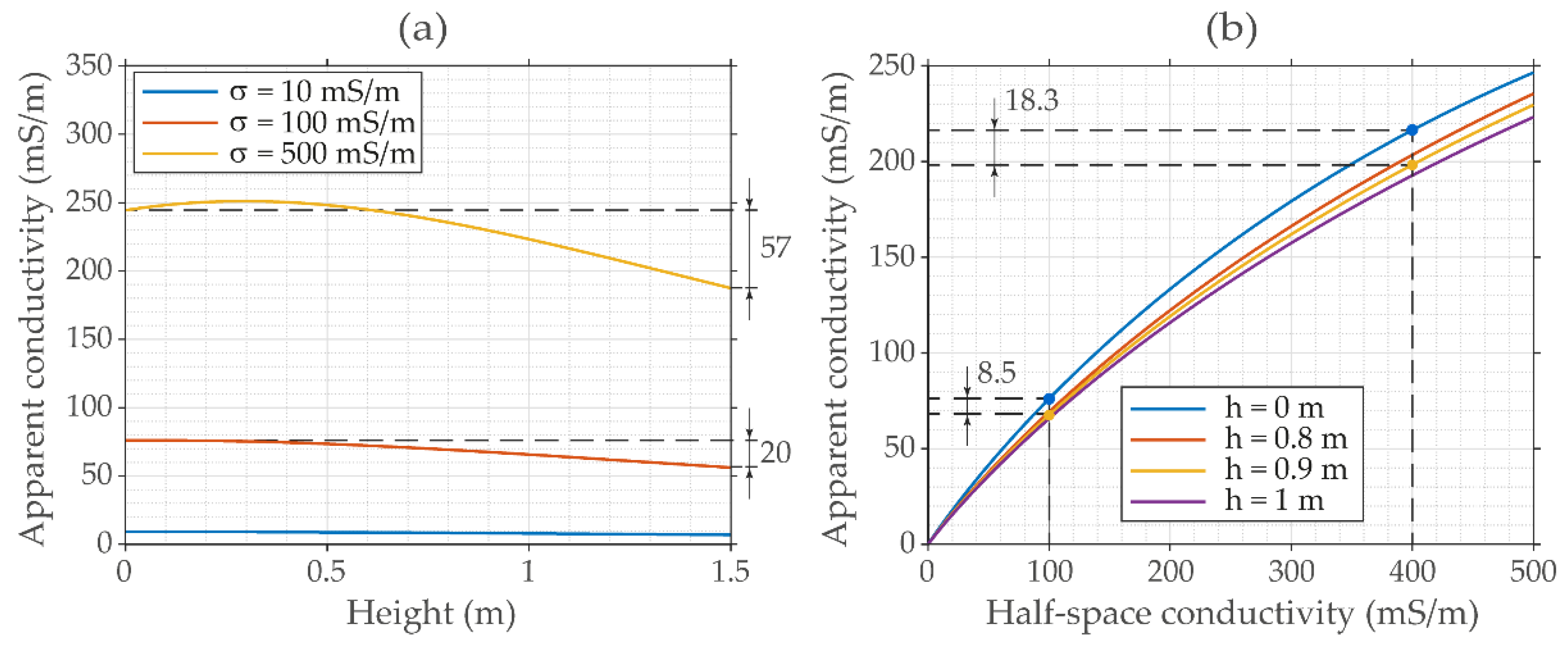
The height at which the ground conductivity meter is used is another survey parameter significant to understand EMI data, for both imaging and mapping uses. In fact, increasing the probe height increases the depth of penetration of the system and so the measurements investigate different, overlapping soil volumes [37,38,48]. This allows use of measurements at different instrumental heights to get quantitative estimates variations of true electrical conductivity with depth, by inversion [19,20,37,49,50]. On the other hand, an increase in the tool height also usually lowers the amplitude of the measured response, which makes it more difficult to detect spatial variations of apparent conductivity [48]. The bias the height introduces in the apparent conductivity is a function of the ground conductivity and usually increases with the conductivity [48]. However, as for the nonlinearity of the electromagnetic response, different devices (coil configurations, coil distances, and operating frequency) experience different biases for the same conductivity. To quantify the bias for the EM31, we simulated its HCP response over a range of half-space conductivity for different operating heights (Figure 9). With the single exception of the low-conductive (σ = 10 mS/m) half-space, where the response is negligibly related to the operating height, Figure 9a shows that in the other cases, the response changes significantly over the range of coil heights, with biases of 20 mS/m and 57 mS/m for a half-space conductivity of 100 mS/m and 500 mS/m, respectively. Figure 9b shows the response over a range of half-space conductivity for heights 0.8, 0.9, and 1 m, which are the most frequently used for the EM31, as well as the one simulated at 0 m as a reference. At a 0.9 m height, for example, the bias amounts to 8.5 mS/m for a 100 mS/m half-space and reaches the values of 18.3 mS/m when the half-space conductivity is 400 mS/m (about the same as the maximum measured in this work).
Apparent conductivity maps across areas with variable topography are often dominated by anomalies related to the elevations of the measurement points [51,52,53]. In fact, topographical variations can affect the bulk electrical characteristics of the materials sensed by the instrument inside its penetration depth. This is the case, for example, when a resistive layer lies above a conductor, such as the water table. In absence of lateral heterogeneities other than topography, the bulk apparent conductivity would increase roughly with a potential function with decreasing elevations [51,52]. As the elevation at the Bacàsara site slopes to the north-east from about 6 m to 2.8 m, the EM31 quadrature response was expected to increase towards the north-east, reflecting the variation of groundwater levels in the area. Therefore, to make the spatial correlation of apparent conductivity unquestionably independent from topography, and then exclusively related to the spatial distribution of conductive landfill materials, we have applied a topographic correction with the empirical procedure suggested by Monier-Williams et al. [51]. The procedure involves first determining a background apparent conductivity trend versus elevation, σbg, which is then used to give a normalised apparent conductivity, C in decibels (dB), from the measured apparent conductivity, σa, by applying the following equation [54]:
C ( x , y ) = 20 log [ σ a ( x , y ) σ b g ( h ) ] ,
where x, y, and h are the spatial coordinates and the elevation of the measurement point. For our case, however, plotting apparent conductivity against elevation (see below in the section Results), no clear trend was noticeable so that it was not possible to uniquely determine the background apparent conductivity as the lower bound of all measurements made at a particular elevation. This is probably due to the strong lateral heterogeneities at the site, which violate the basic assumption for the validity of the procedure [51]. Therefore, we opted for establishing the background apparent conductivity in the area by an alternative procedure, consisting of modelling the EM31 response over a subsurface model “free” from heterogeneities other than topography.
To this end, we started observing that the LIN-corrected EM31 dataset had a bimodal distribution, as successfully assessed by three different criteria known as the bimodality coefficient (BC) [55], Akaike’s information criterion (AIC) [56], and Silverman’s bandwidth test [57]. From a statistical point of view, this means that the dataset results from the combination of two ensembles: one was assumed as composed by background values, and the other by the heterogeneities introduced by landfill materials. In order to separate the two ensembles, we assumed the dataset to be a mixed distribution of the form:
M = p ϕ 1 + ( 1 p ) ϕ 2 ,
where p is the mixing weight and ϕ 1 and ϕ 2 are the probability density functions of the searched component distributions, with mean μi and standard deviation σi. The components and all parameters were estimated using a maximum-likelihood-based method implemented in MATLAB. To estimate the background apparent conductivity, we built a simple subsurface model consisting of one resistive layer over a nonmagnetic conductive half-space. At each measurement point, assuming the groundwater level was at zero elevation, we fixed the thickness of the resistive layer above the water table equal to the ground elevation. Then, the electrical conductivity of the two layers were set up to obtain apparent conductivities across the area with a mean value corresponding to the peak value of the first component of the mixed distribution. Finally, the background apparent conductivities were estimated using the electromagnetic forward modelling code of FDEMtools [44], a free MATLAB software package implementing the numerical algorithms discussed by Deidda et al. [17,20,58].

3. Results

3.1. Preliminary Descriptive Analysis

Descriptive statistics including mean, median, standard deviation (SD), variance, interquartile range (IQR), minimum and maximum values, coefficient of variation (CV), skewness (S), and kurtosis (K) for quadrature and in-phase EM31 responses from 29,428 sampling points are summarised in Table 1.
The raw Q response, expressed as apparent conductivity, averaged 82.4 mS/m, ranging from 5.5 to 207.9 mS/m, while the P response averaged 5.13 ppt ranging from +/− 20.47 ppt, which spans the whole measuring range (full-scale values) of the device. The median values of both data are a little lower than the mean values, indicating that data distributions are positively skewed, as confirmed by skewness values. Moreover, kurtosis indexes show that both data have leptokurtic distributions (with a more acute peak around the mean than a normal distribution). For the in-phase data, in particular, the high kurtosis indicates the substantial presence of outliers.
According to the classification for the coefficient of variation (CV) proposed by Warrick and Nielsen [59], the P component of the EM31 response showed a high variability across the area, as indicated by the CV of 75.52%, while moderate variability (CV of 46.22%) was observed for the Q response. Their difference, however, is not completely due to material heterogeneities. Comparatively examining the two CVs, the higher variability of the P response may partially reflect the presence of small metallic objects randomly spread on the ground surface or in the very near surface across the area. In fact, the P component sensitivity to magnetic permeability is much higher than the Q component sensitivity. On the other hand, the CV of the Q response is underestimated as the spatial variation of the Q component is reduced by the nonlinearity response of the EM31 device.
Following the method of Tukey [60], which is one of the most frequently used tools to detect outliers, all values lying more than one and a half times the interquartile range (IQR) below the first quartile (Q1) and above the third quartile (Q3) were considered outliers. Inspecting both quadrature and in-phase preliminary maps (Figure 10), nearly all outlier values appear to be associated with known metal objects and fences. The linear anomalies depicted at the southern and western borders of the area are the signs of the boundary metal fence. The other anomaly extending from the south-west to the north-east at the western border of the area is, instead, due to a number of old metallic containers, which were there during data acquisition. It is not clear, however, what the origin is of the outliers of the quadrature response in the northern part of the area (Figure 10b). However, it seems to be excluded that it is due to metallic objects; no such objects were visible during the acquisition and no high in-phase values were measured in this area.
Apart from these anomalies in the Q response and the other expected ones, the map in Figure 10 also shows areas of very high apparent conductivities where relatively low P values were measured. This outcome suggested that high-conductive nonmagnetic materials, such as clay strata, groundwater, or conductive waste materials, could be the cause of the signal in these areas.

3.2. Data Processing and Analysis

3.2.1. Correction for the Nonlinearity and for the Height of Measurements

After removing the measurements identified as outliers in both Q and P responses, the filtered Q response ranges from 5.5 mS/m to about 188.6 mS/m; all these values are above the conductivity threshold adopted here for the validity of the LIN condition (see Section 2.3.2). Therefore, all data are more biased towards lower values than the true ones, but with different biases from one location to another as a function of the actual conductivity. As a consequence, the spatial distribution of the measured apparent conductivity may represent a distorted distribution of the correct apparent conductivity, and both shape and size of the high-conductivity anomalies may come out inaccurate.
In order to map the apparent conductivity minimising the above-mentioned distortions, raw data (without the outliers) have been corrected with the procedure suggested by Beamish [38]. To that end, we firstly simulated measured data in the range from 0 mS/m to 500 mS/m true conductivity, assuming the operation height of the EM31 at 0.9 m above ground (Figure 8); then, the simulated response was estimated by a least-squares fitting of the data ( σ a ), using a fourth-order polynomial expressed as:
LIN   σ a = n = 0 n = 4 c n σ a n ,
where cn are the coefficients whose values, together with the 95% confidence bounds, are listed in Table 2. The root mean squared error (RMSE) of the least-squares fit was 0.0263.
The map of the corrected apparent conductivity, along with that of the raw data (Figure 10a), is shown in Figure 11 with the same color scale for comparison. To better appreciate the changes made by the correction for the nonlinearity and, in particular, to show how these changes are distributed over the area, Figure 11c also shows the map of the point-by-point (numerical) difference between the LIN ECa and the raw apparent conductivity (the Q response). Due to the large range of apparent conductivity, the corrected values increase very differently across the area, enhancing lateral gradients that help in delineating both size and shape of anomalous areas.
To inspect unimodality or bimodality of both the LIN-corrected apparent conductivity and in-phase (without the outliers) data, of which a summary statistics is reported in Table 3, we computed the values of the bimodality coefficient (BC) and the Akaike’s information criteria (AIC) using the codes mentioned in [61] (Appendix), while we applied the Silverman’s bandwidth test using a MATLAB function [62] based on the bootstrap method described in [63]. The BC got values of 0.5598 for the apparent conductivity (ECa) and 0.3334 for the in-phase component, while AIC returned values of 0.0253 and 0.0020, respectively. As shown by [61], the empirical BC, which ranges from 0 to 1, suggests bimodality when it assumes values greater than 0.555; instead, AIC indicates bimodality for positive values. Silverman’s bandwidth test results, shown in Table A1 (Appendix A), suggest bimodality for the ECa and unimodality for the in-phase component. Therefore, based on these results and on the BC and AIC values, we assumed the LIN ECa and in-phase distributions as bimodal and unimodal distributions, respectively. For the LIN ECa, applying the relationship (5) we found a mixed-to-normal distribution defined with a vector μ = [ 81.42 ; 177.07 ] of means, a vector σ = [ 25.13 ; 60.46 ] of standard deviations, and a vector p = [ 0.52 ; 0.48 ] of weights (Figure 12).

3.2.2. Geostatistical Analysis

Spatial statistics were then used to produce reliable maps and the relevant estimation errors. All variograms were computed with a lag distance of 3.3 m, with a tolerance of ±0.5 the lag distance, to a maximum distance of about 120 m, which is about one third of the diagonal length of the investigated area. The graphical representation of the omnidirectional variograms for both filtered (without outliers), LIN ECa, and filtered P component are shown in Figure 13. The notable feature of both omnidirectional variograms is that they do not have a stable sill so that both LIN ECa and P component data have a global trend. A nested spherical and power model was fitted to the apparent conductivity variogram while the variogram of the P data was fitted well by a nested spherical and linear model with a nugget effect, which is an indicator of short-range randomness due to the presence of small metallic objects randomly spread in the area. Table 4 summarises the parameters of the variogram models (Appendix B) fitted to the data and their validation information.
In order to better visualise the spatial variability along different directions and to find the direction of the trend, we also calculated variogram maps and directional variograms, spanning all angle directions at 3° intervals. Thanks to the very high number of observations, we were able to reliably calculate variograms with a small angular tolerance (±9°) and high detail. Figure 14 shows the plots for the LIN ECa, which is the variable on which we focus our attention in the following sections.
The variogram map shows no evidence of anisotropy to lag distances of about 35–37 m, since the variogram values from all directions are nearly the same at this range (see the dashed circle in Figure 14a). The sill variances change beyond the range of about 35–37 m. The sill remains flat along the north-west-to-south-east direction, whereas in the south-west-to-north-east direction it continues to increase for all lag distances. Figure 14b shows the experimental and fitted variograms along the angular directions of the greatest (N136°) and the smallest (N46°) spatial continuities. Along the first angular direction, the variogram is stationary and is well-fitted with a spherical model. In the other direction, the non-stationary variogram is fitted by a nested spherical and power model. A very small nugget effect was calculated in both cases. The notable feature of the non-stationary variogram is that it is concave over lag distances beyond the range, indicating a trend in the apparent conductivity data along the N46° direction. This can be explained by the topography, which has a maximum slope along the same direction.

3.2.3. Correlation between Conductivity and Topography

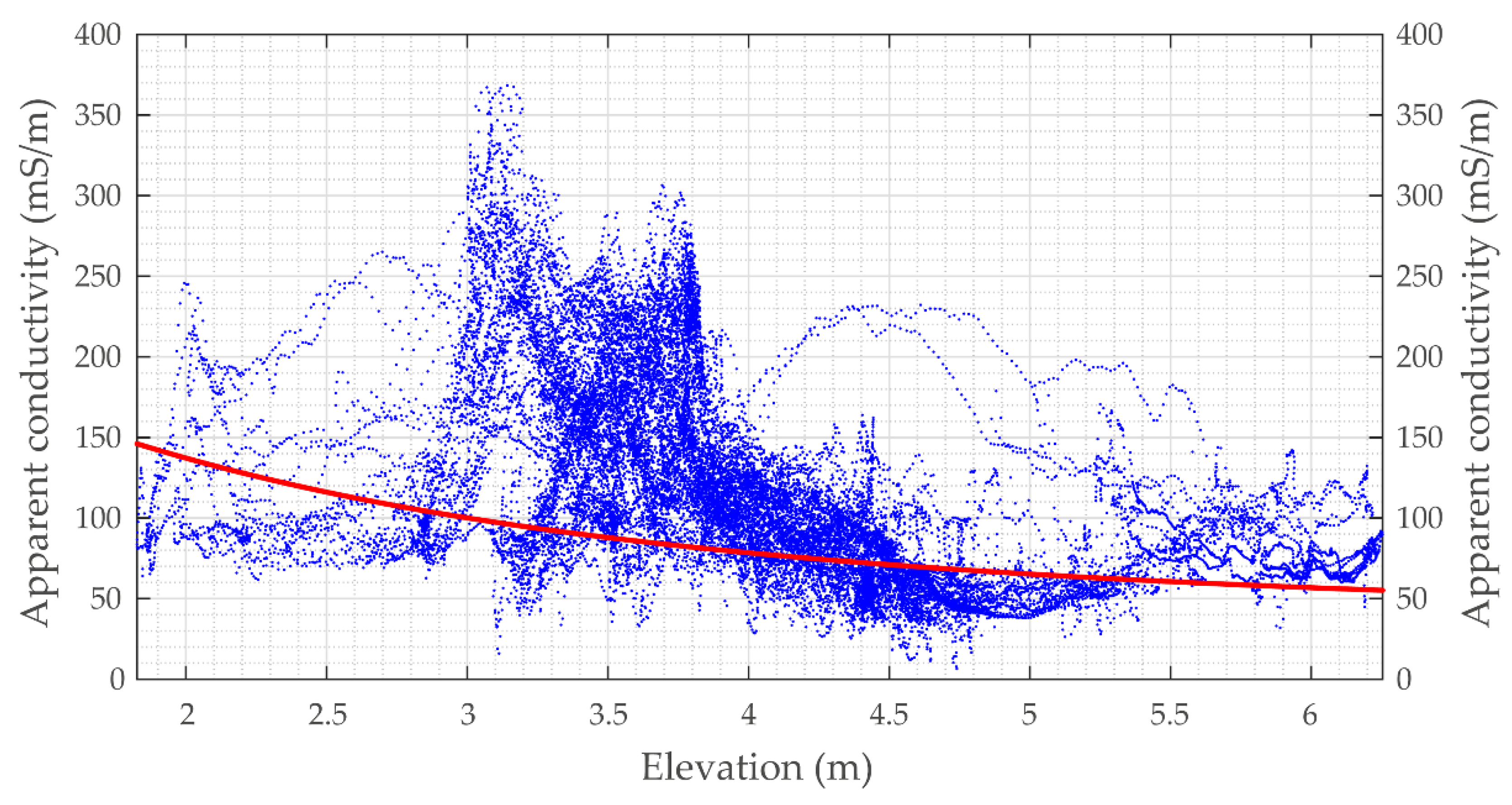
Figure 15 shows a plot of the LIN ECa versus elevation that we initially considered to estimate the correlation between them, as suggested by [51]. As mentioned above, points of the scatter plot do not have a well-defined lower limit allowing a curve representing the background apparent conductivity to be drawn.
However, statistical and geostatistical analyses clearly indicate that data suffer the influences of topographical variations. The variogram analysis clearly proves that apparent conductivity shows a trend along the direction of the greatest slope of the elevation. Moreover, the bimodality distribution of the LIN ECa allows us to consider it as the result of two data populations (Figure 12b). We related the population with a mean of 81.42 mS/m to the background apparent conductivity, while the other, with a mean value of 177.07 mS/m, was related to the heterogeneities due to landfill materials. Therefore, we estimated the background apparent conductivity in the following way: for each point where the experimental dataset was collected, we set up a simple nonmagnetic subsurface model consisting of one layer, and having an electrical conductivity of 40 mS/m and a thickness equal to the ground elevation, over a half-space with an electrical conductivity of 300 mS/m. Then, using FDEMtools [44] we simulated nonlinear apparent conductivities adopting an EM31 device operating at the height of 0.9 m, the same that was used for the experimental data acquisition. Finally, after removing the bias introduced by the nonlinearity of the instrument, we were able to get apparent conductivity values across the area with a mean value (82.07 mS/m) very close to the peak value of the first component of the mixed distribution (Figure 12b). The red curve in Figure 15 is the plot of the estimated background of the LIN apparent conductivity versus elevation, while Figure 16 shows the map of the LIN apparent conductivity that we used as the background conductivity to normalise the LIN-corrected experimental one.

3.3. Apparent Conductivity Map Interpretation

Figure 17 shows apparent conductivity and in-phase maps generated interpolating filtered data into a regular grid with a 3 × 3 m cell size, applying the universal kriging interpolation method with the appropriate variogram models. The pattern of the LIN ECa, which ranges from 10 mS/m to about 430 mS/m, clearly reveals areas of both low and very high conductivity (Figure 17a). Apart from some conductive zones at the southern and western borders of the site, which are still visible although the outliers have been filtered out, more than half of the site is characterised by conductivities higher than 100 mS/m. In particular, two strong conductive anomalies can be distinguished in the map. The wider one, in the central-eastern portion of the site (area A), is irregular in shape but it appears elongated as a whole in the south-to-southeast, north-to-north-west direction; the smaller one is located in the north-western portion of the site (area B), with an elongated shape in the south-to-south-west, north-to-north-east direction. The in-phase map (Figure 17b) shows filtered values (without outliers) ranging from 0 ppt to about 10 ppt, with a spatial pattern similar to that of the apparent conductivity; the areas with higher conductivity values (A and B) in general coincide with the higher in-phase values, which are consistent with those arising from the conductive property of the material (see the simulated P response of the EM31 over a range of half-space conductivity extending to 500 mS/m in Figure S3 of the Supplementary Materials). The lowest ECa values lie in the south-western part of the site but low values are also found in two smaller areas near the north-western and north-eastern corners.
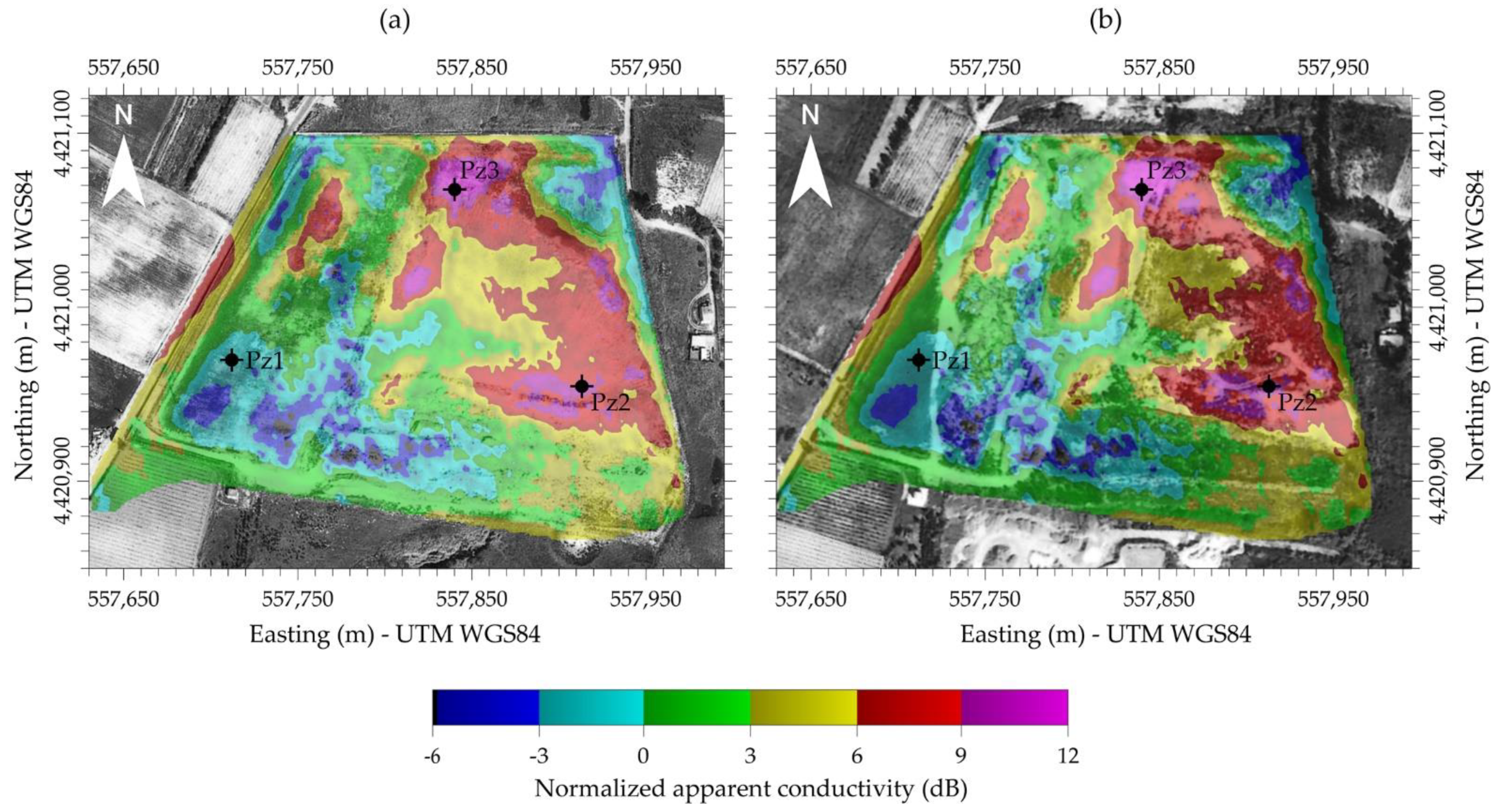
In order to interpret from a qualitative point of view the conductive anomalies and to identify their causes, the LIN ECa map was overlain onto the 1989 and 1995 aerial photographs (Figure 18). The wider anomaly (in area A) almost perfectly matches the fan-shaped area which had been rearranged between 1988 and 1989 (Figure 5), while the anomaly in area B matches the northern part of the wider dump, well visible in the 1995 aerial photograph (Figure 6). The observed good match between historical photographs and the high-conductive areas looks even better in Figure 19, where the normalised apparent conductivity, contoured with a constant logarithmic interval (see equation 3), is shown. Excluding the areas at the southern and western borders of the site where the effects of some surface man-made features (fences and metallic containers) may be still present, we assumed the 0 dB contour as a good representation of the waste boundary at the site (Figure 19).
The spatial match between the normalised conductive anomalies and the details in aerial photographs is apparent. The way the electromagnetic data has drawn an accurate picture of different moments of the landfill history, and the excellent way the FDEM mapping synthesised this history, simultaneously portraying these pictures, is impressive and somewhat surprising. The conductance signatures of the landfill materials dumped at the site over the years appear well-defined and distinct, despite the successive various earthworks over time. The anomalies of high apparent conductivity may indeed be due to the presence of highly conductive materials in the landfill (e.g., organic waste in an advanced degree of biodegradation), which probably contain leachate or which are at least in contact with groundwater with a high content of totally dissolved solids.

4. Ground Truthing

In a follow-up geophysical survey, based on the results described in this work, a total of 14 electrical resistivity tomography (ERT) and induced polarisation tomography (IP) profiles were conducted, thirteen of which were inside, and one was outside the area (Figure 20a). Data were collected with a Syscal Pro resistivity metre by performing roll-along surveys with 48 electrodes with a 2 m spacing, deployed in a dipole-dipole array. Both apparent resistivity and IP data were inverted using the Res2Dinv software package.
For a quantitative interpretation of the geophysical surveys after they were completed and before completing the site characterisation plan, three boreholes were core drilled. The location of boreholes (Figure 19 and Figure 20a) was selected to investigate the subsurface materials in three areas, where marked differences in both EMI apparent conductivity and ERT resistivity were observed. Borehole Pzl was located in an area that should have been undisturbed on the basis of aerial photography and geophysical results; it should not have intersected, if not marginally, landfill materials. The other two boreholes were located in two areas with high values of electrical conductivity, where waste materials were supposed to be found. In detail, borehole Pz2 was located in an area where topsoil and very shallow materials showed relatively low resistivity (about 30 Ωm), while borehole Pz3 was drilled in an area with highly resistive shallow materials (>500 Ωm). The stratigraphic columns for each borehole are sketched in Figure 20c.
Near borehole Pz1, ERT L1 (Figure 20b) shows resistivity values between 20 and 80 Ωm, which are quite similar to the background values detected with the ERT profile conducted outside the area (not shown in Figure 20a). Although the stratigraphy shows the presence of waste materials (even if in minimum quantity) in the shallowest portion of the soil (down to 1.6 m below ground surface), the core materials were typical of the local geology (from fine-grained sands to silty sands, with increasing moisture content). Besides, groundwater sampled at a depth of 5.20 m (−0.4 m above sea level [asl]) did not show signs of contamination, although it was found lightly brackish, with a specific conductance of 1463 μS/cm (146.3 mS/m), probably due to the presence of silty sand and sandy clay. Neither the information from borehole Pz1 nor the interpreted ERT showed the presence of waste materials or signs of contamination. This totally agrees with what the aerial photos documented and with what the electromagnetic map shows.
At the location of borehole Pz2, beneath the shallowest layer made of fine-grained sand with gravel mixed with waste, 4 m (between 2.7 m and −1.3 m asl) of uncompacted waste materials with high moisture content at the bottom are present. As shown by ERT line L2 (Figure 20b), the electrical resistivity lowers to 5 Ωm at the bottom of the layer and it retains similar values even beneath the waste layer (−6 m asl). Water chemistry analyses from samples collected at a depth of 7 m (−3.6 m asl) gave a highly specific conductance of 6120 μS/cm (612 mS/m) that justifies the low ERT values near the borehole. These low resistivity values, which are in a good agreement with the apparent electrical conductivities mapped through the electromagnetic survey, were attributed to a conductive layer made of materials saturated by highly conductive fluids and with a concentration of pollutants above regulation limits (from the chemical analysis of the waters carried out for the characterisation plan).
Comparing the stratigraphy of borehole Pz3 with the ERT line L3, a perfect match is evident between the top layer of dry waste and the shallow resistive portion; the bottom of the waste materials, at a depth of 1.70 m, coincides with the iso-resistive 100 Ωm at the same depth (1.5 m asl). Going deeper and up to a depth of 3.70 m, the silty sands and wet silty sands, locally with waste, are responsible for the resistivity lowering from 100 Ωm to about 10 Ωm. Underneath, between elevations of −0.5 m and −1.70 m asl, a second layer of waste is present, this time completely saturated with water, as it is located under the water table. In the corresponding portion of the tomographic section, the electric resistivity shows values of less than 10 Ωm, reaching its minimum values under the waste layer. These resistivity values agree with the specific conductance (6720 μS/cm) of the water collected at a depth of 6 m (−2.80 m asl). The characterisation plan showed the presence of pollutants with concentrations exceeding the legal limit, and it ascertained that the most conductive portion imaged by the ERT below the waste encountered by borehole Pz3 was due to the presence of a leachate plume in the fine-grained sands down to an elevation of about −7 m asl. All this represents a further ground truth of the electromagnetic mapping survey.

5. Conclusions

At the time of the geophysical survey, nearly 25 years had elapsed since the time landfill operations probably started at the Bacàsara site. In spite of this, it was possible to successfully verify the presence of waste, corresponding to the presence of electrical conductivity anomalies produced by the decomposition processes active for decades on the waste materials. The effectiveness of ground electrical conductivity mapping to delineate the lateral extent of abandoned waste disposal sites, dumps, or illegal landfills has long been demonstrated. However, care must be paid when a quantitative analysis of the EMI data is made. As landfill waste generally has high electrical conductivity, the limits posed by the low induction number assumption are usually exceeded, and the instruments manifest a nonlinear response that must be accounted for in order to produce maps that, even though still in the form of apparent electrical conductivity, mimic at best the lateral variability of electrical conductivity heterogeneities associated with the presence of landfill waste. Topography and instrument operating heights are other factors to take into account to derive quantitative conclusions about the electrical conductivity of the in-situ material.
In this study we demonstrate the need and value for an appropriate processing and mapping of EMI data in such situations, in order to reduce errors from bias due to the nonlinear device response and the operating height. We also demonstrate how statistical and geostatistical data analyses, combined with the modelling of the electromagnetic device response, represent a suitable procedure to estimate the background apparent conductivity, which is required to remove the bias due to the topographical variations. This procedure may be a valuable alternative for estimating the background conductivity, when lateral heterogeneities in the subsoil prevent a clear correlation between conductivity and topography. The results show how a quantitative assessment of the electrical conductivity values allows a more accurate delineation of the landfill extent. Ground truthing data provided by historical aerial photographs and by three boreholes core-drilled on the basis of the apparent conductivity map provided independent evidence concerning the soundness of the results we obtained.
The present study represents yet one good example of how a combination of extensive, non-invasive geophysical measurements, integrated with remote sensing analysis (historical aerial photographs), and supported by local ground truthing, can provide answers to the need for landfill characterisation, even with only scattered and limited a priori information.

Supplementary Materials

The following supporting information can be downloaded at: https://www.mdpi.com/article/10.3390/rs14040878/s1, Figure S1: Aerial photographs taken in 1997, 1998, and 1999; Figure S2: Aerial photographs taken in 2001, 2002, 2003, and 2006. Figure S3: Simulated theorical in-phase component over a range of half-space conductivities extending to 500 mS/m.

Author Contributions

Conceptualisation, G.P.D., A.C.P. and G.C.; methodology, G.P.D., M.H., A.C.P., I.B. and G.C.; software, G.P.D.; validation, G.P.D., M.H., A.C.P., I.B. and G.C.; formal analysis, G.P.D., M.H., A.C.P., I.B. and G.C.; investigation, G.P.D.; resources, G.P.D.; data curation, G.P.D., M.H., A.C.P., I.B. and G.C.; writing—original draft preparation, G.P.D., M.H., A.C.P., I.B. and G.C.; writing—review and editing, G.P.D., M.H., A.C.P., I.B. and G.C.; visualisation, G.P.D., M.H., A.C.P., I.B. and G.C.; supervision, G.P.D., M.H., A.C.P., I.B. and G.C.; project administration, G.P.D.; funding acquisition, G.P.D. All authors have read and agreed to the published version of the manuscript.

Funding

This work was funded by the Municipality of Tortolì.

Data Availability Statement

The data presented in this study are available on request from the corresponding author.

Acknowledgments

We thank the Municipality of Tortolì for granting permission to publish the data described here. Special thanks are also due to Luigi Noli and Mario Sitzia for their invaluable contribution to the collection of field data. We would also like to thank the Academic Editor and the Reviewers for their useful comments and suggestions that helped to improve the manuscript.

Conflicts of Interest

The authors declare no conflict of interest.

Abbreviations

The following abbreviations are used in this manuscript:
AICAkaike’s information criterion
BInduction number
BCBinomial coefficient
CVCoefficient of variation
dBDecibel
ECaApparent electrical conductivity
EMIElectromagnetic induction
ERTElectrical resistivity tomography
FDEMFrequency-domain electromagnetic
GPSGlobal positioning system
HCPHorizontal coplanar
IGMItalian Military Geographic Institute
IPInduced polarization
IQRInterquartile range
KKurtosis
LINLow induction number
LIN ECaApparent electrical conductivity at LIN condition
PIn-phase component
QQuadrature component
Q1First quartile
Q3Third quartile
RMSERoot-mean-square error
SSkewness
SDStandard deviation
UTMUniversal Transverse Mercator
VCPVertical coplanar
WGS84World Geodetic System 84

Appendix A

To test the multimodality of both ECa and in-phase data we used the following MATLAB function:
[ H , P , h ]   = bootmode ( x , m , B , k e r n a l ) ,
available online at the link www.mathworks.com/matlabcentral/fileexchange/66671-bootmode (accessed on 2 December 2021). The input parameters are the data vector, x, the modality or the number of modes, m, the number of bootstrap replicates, B, and the distribution density, kernel. The outputs are the critical bandwidth h, the significance level P, also indicated as p-value, and a parameter H whose possible values 0 or 1 indicate that the null hypothesis cannot or can be rejected at the 5% significance level.
Table A1 lists critical bandwidths and significant levels for test of null hypothesis that the distribution density has at most m modes against the alternative hypothesis that it has more than m modes. In particular, the p-values are computed by simulating from a critical density, using a Gaussian density kernel and B = 1000 replications of 28,970 data in each case. The grey rows in the Table A1 show the test results indicating the estimated modality for the two datasets, that is, the smallest m where the null hypothesis can be accepted.
Table A1. Results from multimodality testing using the Gaussian kernel.
Apparent ConductivityIn-Phase Component
ModalityCritical BandwidthSignificance LevelHCritical BandwidthSignificance LevelH
111.0880.000s10.24370.3400
27.59710.18000.23880.0201
36.87760.05600.18810.0720
46.16450.02810.16370.1500
55.00210.17000.11900.9180

Appendix B

Spherical Model
The spherical model is defined by the equation
γ ( h ) = { 0 , h = 0 C 0 + C [ 3 2 h a 1 2 ( h a ) 3 ] , 0 < h < a C 0 + C , h a  
where C0 is the nugget, C is the partial sill, a is the range.
Power Model
The equation of the power model is
γ ( h ) = C 0 + α h n ,  
where C0 is the nugget, α is the slope, and n is the exponent ( 0 < n < 2 ). The power model has not sill nor range. However, since the slope can be expressed in the terms of equivalent partial sill and equivalent range [64],
α = C e q ( 1 a e q ) n ,  
The power model can be also defined as
γ ( h ) = C 0 + C e q ( h a e q ) n .  
Linear Model
The linear model results from the power model (A3) when the exponent is n = 1 :
γ ( h ) = C 0 + a h  
or, in terms of equivalent parameters,
γ ( h ) = C 0 + C e q h  
putting the equivalent range a e q 1 .

References

  1. Council Directive 1999/31/EC of 26 April 1999 on the landfill of waste. Available online: https://eur-lex.europa.eu/eli/dir/1999/31/oj (accessed on 30 August 2021).
  2. Council Directive 92/43/EEC of 21 May 1992 on the Conservation of Natural Habitats and of Wild Fauna and Flora. Available online: https://eur-lex.europa.eu/eli/dir/1992/43/oj (accessed on 30 August 2021).
  3. Shannon, C.E. Communication in the Presence of Noise. Proc. IRE 1949, 37, 10–21. [Google Scholar] [CrossRef]
  4. Cassiani, G.; Binley, A.; Kemna, A.; Wehrer, M.; Orozco, A.F.; Deiana, R.; Boaga, J.; Rossi, M.; Dietrich, P.; Werban, U.; et al. Noninvasive characterization of the Trecate (Italy) crude-oil contaminated site: Links between contamination and geophysical signals. Environ. Sci. Pollut. Res. 2014, 21, 8914–8931. [Google Scholar] [CrossRef] [PubMed]
  5. Boaga, J.; Ghinassi, M.; D’Alpaos, A.; Deidda, G.P.; Rodriguez, G.; Cassiani, G. Geophysical investigations unravel the vestiges of ancient meandering channels and their dynamics in tidal landscapes. Sci. Reports 2018, 8, 1–8. [Google Scholar] [CrossRef] [Green Version]
  6. Lesch, S.M.; Strauss, D.J.; Rhoades, J.D. Spatial Prediction of Soil Salinity Using Electromagnetic Induction Techniques: 1. Statistical Prediction Models: A Comparison of Multiple Linear Regression and Cokriging. Water Resour. Res. 1995, 31, 373–386. [Google Scholar] [CrossRef]
  7. Martinelli, P.; Duplaá, M.C. Laterally filtered 1D inversions of small-loop, frequency-domain EMI data from a chemical waste site. Geophysics 2008, 73, F143–F149. [Google Scholar] [CrossRef] [Green Version]
  8. Paine, J.G. Determining salinization extent, identifying salinity sources, and estimating chloride mass using surface, borehole, and airborne electromagnetic induction methods. Water Resour. Res. 2003, 39, 1059. [Google Scholar] [CrossRef] [Green Version]
  9. Pellerin, L. Applications of Electrical And Electromagnetic Methods for Environmental And Geotechnical Investigations. Surv. Geophys. 2002, 23, 101–132. [Google Scholar] [CrossRef]
  10. Yao, R.; Yang, J. Quantitative evaluation of soil salinity and its spatial distribution using electromagnetic induction method. Agric. Water Manag. 2010, 97, 1961–1970. [Google Scholar] [CrossRef]
  11. Jadoon, K.Z.; Moghadas, D.; Jadoon, A.; Missimer, T.M.; Al-Mashharawi, S.K.; McCabe, M.F. Estimation of soil salinity in a drip irrigation system by using joint inversion of multicoil electromagnetic induction measurements. Water Resour. Res. 2015, 51, 3490–3504. [Google Scholar] [CrossRef] [Green Version]
  12. Moghadas, D.; Jadoon, K.Z.; McCabe, M.F. Spatiotemporal monitoring of soil water content profiles in an irrigated field using probabilistic inversion of time-lapse EMI data. Adv. Water Resour. 2017, 110, 238–248. [Google Scholar] [CrossRef] [Green Version]
  13. Monteiro Santos, F.A.; Triantafilis, J.; Bruzgulis, K. A spatially constrained 1D inversion algorithm for quasi-3D conductivity imaging: Application to DUALEM-421 data collected in a riverine plain. Geophysics 2011, 76, B43–B53. [Google Scholar] [CrossRef]
  14. Shanahan, P.W.; Binley, A.; Whalley, W.R.; Watts, C.W. The Use of Electromagnetic Induction to Monitor Changes in Soil Moisture Profiles beneath Different Wheat Genotypes. Soil Sci. Soc. Am. J. 2015, 79, 459–466. [Google Scholar] [CrossRef] [Green Version]
  15. Von Hebel, C.; Rudolph, S.; Mester, A.; Huisman, J.A.; Kumbhar, P.; Vereecken, H.; Van Der Kruk, J. Three-dimensional imaging of subsurface structural patterns using quantitative large-scale multiconfiguration electromagnetic induction data. Water Resour. Res. 2014, 50, 2732–2748. [Google Scholar] [CrossRef] [Green Version]
  16. Boaga, J.; Viezzoli, A.; Cassiani, G.; Deidda, G.P.; Tosi, L.; Silvestri, S. Resolving the thickness of peat deposits with contact-less electromagnetic methods: A case study in the Venice coastland. Sci. Total Environ. 2020, 737, 139361. [Google Scholar] [CrossRef]
  17. Deidda, G.P.; Díaz de Alba, P.; Rodriguez, G.; Vignoli, G. Inversion of Multiconfiguration Complex EMI Data with Minimum Gradient Support Regularization: A Case Study. Math. Geosci. 2020, 52, 945–970. [Google Scholar] [CrossRef] [Green Version]
  18. Schultz, G.; Ruppel, C. Inversion of inductive electromagnetic data in highly conductive terrains. Geophysics 2005, 70, G16–G28. [Google Scholar] [CrossRef]
  19. Deidda, G.P.; Bonomi, E.; Manzi, C. Inversion of electrical conductivity data with Tikhonov regularization approach: Some considerations. Ann. Geophys. 2003, 46, 549–558. [Google Scholar]
  20. Deidda, G.P.; Fenu, C.; Rodriguez, G. Regularized solution of a nonlinear problem in electromagnetic sounding. Inverse Probl. 2014, 30, 125014. [Google Scholar] [CrossRef] [Green Version]
  21. Nobes, D.C.; Armstrong, M.J.; Close, M.E. Delineation of a landfill leachate plume and flow channels in coastal sands near Christchurch, New Zealand, using a shallow electromagnetic survey method. Hydrogeol. J. 2000, 8, 328–336. [Google Scholar] [CrossRef]
  22. Noguera, J.F.; Rivero, L.; Font, X.; Navarro, A.; Martínez, F. Simultaneous use of geochemical and geophysical methods to characterise abandoned landfills. Environ. Geol. 2002, 41, 898–905. [Google Scholar] [CrossRef]
  23. Woldt, W.E.; Hagemeister, M.E.; Jones, D.D. Characterization of an Unregulated Landfill Using Surface-Based Geophysics and Geostatistics. Groundwater 1998, 36, 966–974. [Google Scholar] [CrossRef]
  24. Boudreault, J.P.; Dubé, J.S.; Chouteau, M.; Winiarski, T.; Hardy, É. Geophysical characterization of contaminated urban fills. Eng. Geol. 2010, 116, 196–206. [Google Scholar] [CrossRef]
  25. Caterina, D.; Isunza Manrique, I.; Inauen, C.; Watlet, A.; Dashwood, B.; De Rijdt, R.; Dumont, G.; Chambers, J.; Nguyen, F. Contribution of geophysical methods to the study of old landfills: A case study in Onoz (Belgium). In Proceedings of the 17th International Waste Management an Landfill Symposium, Santa Margerita di Pula (CA), Italy, 30 September–4 October 2019; p. 15. [Google Scholar]
  26. Yannah, M.; Martens, K.; Van Camp, M.; Walraevens, K. Geophysical exploration of an old dumpsite in the perspective of enhanced landfill mining in Kermt area, Belgium. Bull. Eng. Geol. Environ. 2019, 78, 55–67. [Google Scholar] [CrossRef]
  27. Di Maio, R.; Fais, S.; Ligas, P.; Piegari, E.; Raga, R.; Cossu, R. 3D geophysical imaging for site-specific characterization plan of an old landfill. Waste Manag. 2018, 76, 629–642. [Google Scholar] [CrossRef] [PubMed]
  28. Dumont, G.; Robert, T.; Marck, N.; Nguyen, F. Assessment of multiple geophysical techniques for the characterization of municipal waste deposit sites. J. Appl. Geophys. 2017, 145, 74–83. [Google Scholar] [CrossRef]
  29. Green, A.; Lanz, E.; Maurer, H.; Boerner, D. A template for geophysical investigations of small landfills. Lead. Edge 1999, 18, 248–254. [Google Scholar] [CrossRef]
  30. Montes, R.; Martínez-Graña, A.; Martínez Catalán, J.; Arribas, P.; Sánchez San Román, F.; Zazo, C. Integration of GIS, Electromagnetic and Electrical Methods in the Delimitation of Groundwater Polluted by Effluent Discharge (Salamanca, Spain): A Case Study. Int. J. Environ. Res. Public Health 2017, 14, 1369. [Google Scholar] [CrossRef] [PubMed] [Green Version]
  31. Senos Matias, M.; Marques da Silva, M.; Ferreira, P.; Ramalho, E. A geophysical and hydrogeological study of aquifers contamination by a landfill. J. Appl. Geophys. 1994, 32, 155–162. [Google Scholar] [CrossRef]
  32. Soupios, P.; Papadopoulos, N.; Papadopoulos, I.; Kouli, M.; Vallianatos, F.; Sarris, A.; Manios, T. Application of integrated methods in mapping waste disposal areas. Environ. Geol. 2007, 53, 661–675. [Google Scholar] [CrossRef]
  33. Vaudelet, P.; Schmutz, M.; Pessel, M.; Franceschi, M.; Guérin, R.; Atteia, O.; Blondel, A.; Ngomseu, C.; Galaup, S.; Rejiba, F.; et al. Mapping of contaminant plumes with geoelectrical methods. A case study in urban context. J. Appl. Geophys. 2011, 75, 738–751. [Google Scholar] [CrossRef]
  34. Wang, T.P.; Chen, C.C.; Tong, L.T.; Chang, P.Y.; Chen, Y.C.; Dong, T.H.; Liu, H.C.; Lin, C.P.; Yang, K.H.; Ho, C.J.; et al. Applying FDEM, ERT and GPR at a site with soil contamination: A case study. J. Appl. Geophys. 2015, 121, 21–30. [Google Scholar] [CrossRef]
  35. Wait, J.R. Mutual coupling of loops lying on the ground. Geophysics 1954, 19, 290–296. [Google Scholar] [CrossRef]
  36. Wait, J.R. Mutual Electromagnetic Coupling of Loops over a Homogeneous Ground. Geophysics 1955, 20, 630–637. [Google Scholar] [CrossRef]
  37. McNeill, J.D. Electromagnetic Terrain Conductivity Measurements at Low Induction Numbers; Geonics Ltd.: Mississauga, ON, Canada, 1980. [Google Scholar]
  38. Beamish, D. Low induction number, ground conductivity meters: A correction procedure in the absence of magnetic effects. J. Appl. Geophys. 2011, 75, 244–253. [Google Scholar] [CrossRef] [Green Version]
  39. Goovaerts, P. Geostatistics for Natural Resources Evaluation; Oxford University Press: Oxford, UK, 1997; ISBN 0195115384. [Google Scholar]
  40. Webster, R.; Oliver, M.A. Geostatistics for Environmental Scientists, 2nd ed.; John Wiley & Sons Ltd.: Chichester, UK, 2007; ISBN 978-0-470-02858-2. [Google Scholar]
  41. Montero, J.M.; Fernández-Avilés, G.; Mateu, J. Spatial and Spatio-Temporal Geostatistical Modeling and Kriging; John Wiley & Sons Ltd.: Chichester, UK, 2015; ISBN 9781118413180. [Google Scholar]
  42. Benson, R.C.; Glaccum, R.A.; Noel, M.R. Geophysical techniques for sensing buried wastes and waste migration: An application review. In Proceedings of the Surface and Borehole Geophysical Methods in Ground Water Investigations: NWWA/EPA Conference; Nielsen, D.R., Curl, M., Eds.; Natl Water Well Assn: San Antonio, TX, USA, 1984; pp. 533–566. [Google Scholar]
  43. Caminha-Maciel, G.; Figueiredo, I. Error Analysis in Measured Conductivity under Low Induction Number Approximation for Electromagnetic Methods. ISRN Geophys. 2013, 2013, 1–4. [Google Scholar] [CrossRef]
  44. Deidda, G.P.; Díaz de Alba, P.; Fenu, C.; Lovicu, G.; Rodriguez, G. FDEMtools: A MATLAB package for FDEM data inversion. Numer. Algorithms 2020, 84, 1313–1327. [Google Scholar] [CrossRef] [Green Version]
  45. Callegary, J.B.; Ferre, T.P.A.; Groom, R.W. Vertical Spatial Sensitivity and Exploration Depth of Low-Induction-Number Electromagnetic-Induction Instruments. Vadose Zo. J. 2007, 6, 158–167. [Google Scholar] [CrossRef]
  46. Wait, J.R. A note on the electromagnetic response of a stratified earth. Geophysics 1962, XXVII, 382–385. [Google Scholar] [CrossRef]
  47. Frischknecht, F.C. Electromagnetic Physical Scale Modeling. In Electromagnetic Methods in Applied Geophysics: Volume 1, Theory; Nabighian, M.N., Ed.; Society of Exploration Geophysicists: Houston, TX, USA, 1987; pp. 364–441. ISBN 9781560802631. [Google Scholar]
  48. Morris, E.R. Height-above-ground effects on penetration depth and response of electromagnetic induction soil conductivity meters. Comput. Electron. Agric. 2009, 68, 150–156. [Google Scholar] [CrossRef]
  49. Borchers, B.; Uram, T.; Hendrickx, J.M.H. Tikhonov Regularization of Electrical Conductivity Depth Profiles in Field Soils. Soil Sci. Soc. Am. J. 1997, 61, 1004–1009. [Google Scholar] [CrossRef]
  50. Hendrickx, J.M.H.; Borchers, B.; Corwin, D.L.; Lesch, S.M.; Hilgendorf, A.C.; Schlue, J. Inversion of Soil Conductivity Profiles from Electromagnetic Induction Measurements. Soil Sci. Soc. Am. J. 2002, 66, 673–685. [Google Scholar] [CrossRef]
  51. Monier-Williams, M.E.; Greenhouse, J.P.; Mendes, J.M.; Ellert, N. Terrain Conductivity Mapping with Topographic Corrections at Three Waste Disposal Sites in Brazil. In Geotechnical and Environmental Geophysics: Volume II, Environmental and Groundwater; Ward, S.H., Ed.; Society of Exploration Geophysicists: Houston, TX, USA, 1990; p. 352. ISBN 978-1-56080-001-9. [Google Scholar]
  52. Fröhlich Gugler, A.I.M.; Gex, P. Electromagnetic survey of a Celtic tumulus. J. Appl. Geophys. 1996, 35, 15–25. [Google Scholar] [CrossRef]
  53. Santos, V.R.N.; Porsani, J.L.; Mendonça, C.A.; Rodrigues, S.I.; Deblasis, P.D. Reduction of topography effect in inductive electromagnetic profiles: Application on coastal sambaqui (shell mound) archaeological site in Santa Catarina state, Brazil. J. Archaeol. Sci. 2009, 36, 2089–2095. [Google Scholar] [CrossRef]
  54. Greenhouse, J.P.; Slaine, D.D. The use of the reconnaissance electromagnetic method to map contaminant migration. Groundw. Monit. Remediat. 1983, 3, 47–59. [Google Scholar] [CrossRef]
  55. SAS Institute Inc. SAS/STAT User’s Guide; SAS Institute Inc: Cary, NC, USA, 1989. [Google Scholar]
  56. Akaike, H. A New Look at the Statistical Model Identification. IEEE Trans. Automat. Contr. 1974, 19, 716–723. [Google Scholar] [CrossRef]
  57. Silverman, B.W. Using Kernel Density Estimates to Investigate Multimodality on JSTOR. J. R. Stat. Soc. Ser. B 1981, 43, 97–99. [Google Scholar]
  58. Deidda, G.P.; Díaz de Alba, P.; Rodriguez, G. Identifying the magnetic permeability in multi-frequency EM data inversion. Electron. Trans. Numer. Anal. 2017, 47, 1–17. [Google Scholar] [CrossRef] [Green Version]
  59. Warrick, A.W.; Nielsen, D.R. Spatial Variability of Soil Physical Properties in the Field. In Applications of Soil Physics; Hillel, D., Ed.; Academic Press: New York, NY, USA, 1980; pp. 319–344. ISBN 978-0-12-348580-9. [Google Scholar]
  60. Tukey, J.W. Exploratory Data Analysis, 1st ed.; Addison-Wesley Publishing Company: Reading, MA, USA, 1977; ISBN 9780201076165. [Google Scholar]
  61. Freeman, J.B.; Dale, R. Assessing bimodality to detect the presence of a dual cognitive process. Behav. Res. Methods 2013, 45, 83–97. [Google Scholar] [CrossRef] [PubMed] [Green Version]
  62. Penn, A. Bootmode 2022. Matlab Central File Exchange. Available online: https://www.mathworks.com/matlabcentral/fileexchange/66671-bootmode (accessed on 2 December 2021).
  63. Efron, B.; Tibshirani, R. An Introduction to the Bootstrap, 1st ed.; Chapman and Hall/CRC: Boca Raton, FL, USA, 1994; ISBN 9780412042317. [Google Scholar]
  64. Barbosa, I.C.; Neto, E.A.; Seidel, E.J.; De Oliveira, M.S. Proposal of the spatial dependence evaluation from the power semivariogram model. Bol. Ciências Geodésicas 2017, 23, 461–475. [Google Scholar] [CrossRef] [Green Version]
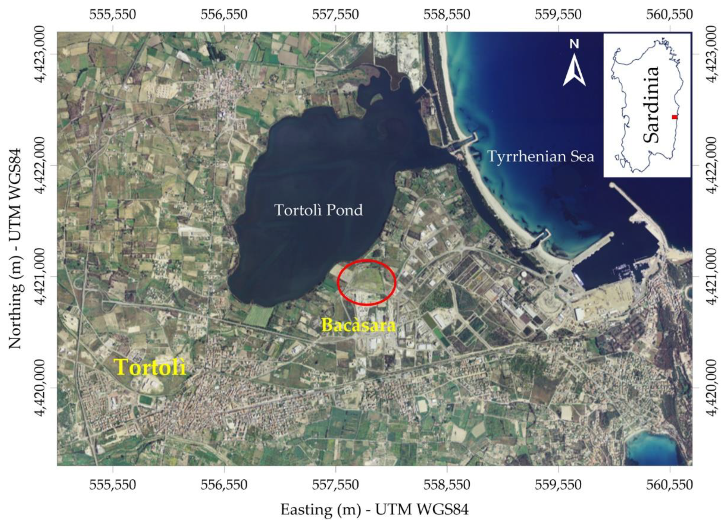
Figure 1. Geographical location of the landfill (red ellipse).
Remotesensing 14 00878 g001
Figure 2. Detailed image of the site with the topographic relief shown by the yellow contours. Isolines are plotted with a contour interval of 20 cm. The blue line indicates the general direction of the groundwater flow while the red circle shows the location of a metal electricity pylon.
Remotesensing 14 00878 g002
Figure 3. (a) Detail of the historical topographic map produced at the scale 1:100,000 (Sheet n. 219—Lanusei—by the Italian Military Geographic Institute (IGM)), derived from maps at the scale 1:25,000, surveyed in 1900, and revised in 1931. The red dashed-line circle shows the location of a pond. (b) Detail of the topographic map surveyed in 1967 (Sheet n. 219, IV, NE—Tortolì by IGM) at the scale 1:25,000.
Remotesensing 14 00878 g003
Figure 4. (a) 1977 aerial photograph (by courtesy of Regione Autonoma della Sardegna); the yellow dashed curve shows the approximated extension of a marshy area. (b) 1983 aerial photograph (by courtesy of Regione Autonoma della Sardegna).
Remotesensing 14 00878 g004
Figure 5. 1989 aerial photograph (by courtesy of Aeronike s.r.l.). Red and blue curves show areas where some works were carried out.
Remotesensing 14 00878 g005
Figure 6. 1995 aerial photograph (by courtesy of Regione Autonoma della Sardegna). The red curve shows the location of dump material.
Remotesensing 14 00878 g006
Figure 7. Location of EM31 survey transects within the survey area.
Remotesensing 14 00878 g007
Figure 8. (a) Simulated electromagnetic quadrature response of the EM31 for HCP configuration, and with coil elevation of 0.9 m, over a range of half-space conductivities extending to 500 mS/m; (b) induction number versus half-space conductivity; (c,d) are zooms of (a,b), respectively. Black solid lines represent the reference linear relation; dashed curves are relative errors. Curves have been simulated with the forward modelling code implemented in FDEMtools [44].
Remotesensing 14 00878 g008
Figure 9. (a) Apparent conductivity bias for different half-space conductivities over a range of coil heights extending to 1.5 m; (b) apparent conductivity bias for different coil heights over a range of half-space conductivities extending to 500 mS/m. Curves have been simulated with the forward modelling code implemented in FDEMtools [44].
Remotesensing 14 00878 g009
Figure 10. (a) raw quadrature response (in mS/m); (b) outliers of the quadrature response (>189.90 mS/m); (c) in-phase response (in ppt); (d) outliers of the in-phase response (<−1.44 ppt and >11.25 ppt). The values of Q1, median, and Q3 for both quadrature and in-phase response are listed in Table 1.
Remotesensing 14 00878 g010
Figure 11. (a) Raw apparent conductivity (Q) map; (b) LIN-corrected apparent conductivity (LIN ECa) map; (c) difference between the maps in (a,b).
Remotesensing 14 00878 g011
Figure 12. (a) Histogram of the LIN ECa with (b) the overlay of its probability density function (red curve) along with the mixture fitting curves (the blak curve is the probability density function of the component ϕ1 in equation (5); the blue curve is the probability density function of the component ϕ2 in equation (5)).
Remotesensing 14 00878 g012
Figure 13. Omnidirectional variograms of the apparent conductivity (a) and the in-phase component (b).
Remotesensing 14 00878 g013
Figure 14. (a) Variogram map of the LIN ECa; (b) directional variograms of the LIN ECa calculated along directions of greatest (N136°) and smallest (N46°) spatial continuity. The radius of the dashed circle in (a) is 37 m, which is the variogram range estimated for all directions.
Remotesensing 14 00878 g014
Figure 15. Plot of apparent conductivity corrected for nonlinearity as a function of elevation. The red line represents the background (LIN) apparent conductivity estimated by a nonlinear forward modelling.
Remotesensing 14 00878 g015
Figure 16. —Background apparent conductivity from nonlinear forward modelling.
Remotesensing 14 00878 g016
Figure 17. (LIN) apparent conductivity map (a) and in-phase component map (b). The dashed lines, which approximate the smoothed 100-mS/m contour line, indicate the boundary of the apparent conductivity anomalies described in the text.
Remotesensing 14 00878 g017
Figure 18. Superposition of the (LIN) apparent conductivity map and the aerial photographs taken in 1989 (a) and in 1995 (b).
Remotesensing 14 00878 g018
Figure 19. Superposition of the normalised apparent conductivity map (in dB) and the aerial photographs taken in 1989 (a) and in 1995 (b). The points indicated as Pz1, Pz2, and Pz3 are the locations of three boreholes drilled after the geophysical survey.
Remotesensing 14 00878 g019
Figure 20. (a) Location of ERT profiles (in red profiles L1, L2, and L3; in yellow the other profiles not described here); (b) ERT results along profiles L1, L2, and L3, plotted with the mapping software package Surfer (Golden Software, LLC); (c) lithologic logs based on core soil analysis from each borehole.
Remotesensing 14 00878 g020
Table 1. Descriptive statistics for raw apparent conductivity and in-phase component of the EM31 response.
Apparent Conductivity (mS/m)In-Phase
(ppt)
Mean82.955.13
Median73.474.79
Standard Deviation38.343.88
Variance1470.1315.04
IQR53.833.17
Q1 154.003.32
Q3 1107.836.49
Minimum5.5−20.47
Maximum207.920.47
CV (%)46.2275.52
Skewness0.940.56
Kurtosis3.6512.01
1 Q1 and Q3 are the first (or lower) and the third (or higher) quartiles, respectively.
Table 2. Coefficients of the fourth-order polynomial obtained by the least-square fitting of simulated response in Figure 8.
c0c1c2c3c4
Value−0.27681.2174.243 × 10−3−6.002 × 10−62.512 × 10−8
95% confidence bounds±0.00920±0.008 × 10⁻³±0.054 × 10⁻⁶±0.011 × 10⁻⁸
Table 3. Descriptive statistics for the LIN apparent conductivity and the filtered in-phase component of the EM31 response.
KERRYPNXLIN ECa
(mS/m)
Filtered In-Phase 1
(ppt)
Mean127.284.88
Median108.844.74
Standard Deviation66.062.19
Variance4364.544.81
IQR94.572.91
Q1 176.433.37
Q3 1171.006.28
Minimum6.54-1.43
Maximum371.0611.22
CV (%)51.9144.95
Skewness0.880.16
Kurtosis3.163.08
1 ECa values without the outliers.
Table 4. Variogram parameters and their validation.
VariableModelSlopeExponentNugget C0Partial Sill CRange a (m)Sill C0 + CR2
ECa 1Spherical 018003723800.9978
Power 1.2 580 (*)30 (*)
In-phase 1Spherical 1.5215.53.50.9829
Linear0.0085
ECa 2Spherical 3023003723300.9504
ECa 3Spherical 3020003727300.9995
Power 1.63 70038
1 Omnidirectional; 2 Directional N136°; 3 Directional N46°; Slope and Exponent are parameters for linear and power models, respectively; R2 measures the goodness of fit. (*) Equivalent partial sill, Ceq, and equivalent range, aeq [64].
Publisher’s Note: MDPI stays neutral with regard to jurisdictional claims in published maps and institutional affiliations.