
A New Methodology for Bridge Inspections in Linear Infrastructures from Optical Images and HD Videos Obtained by UAV


Abstract
:
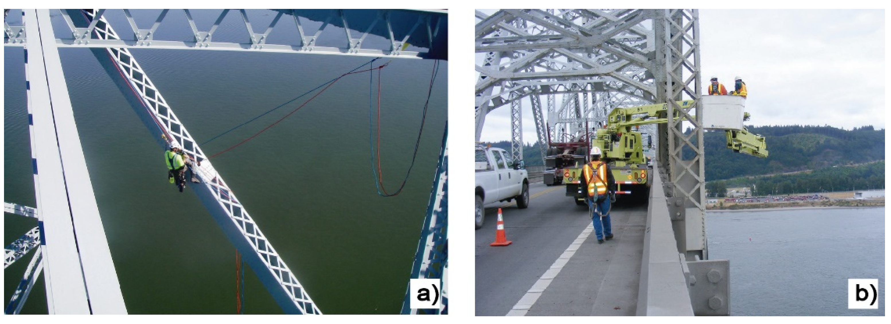
1. Introduction
2. Materials and Methods
2.1. Common Damages of Structures
- Leaching/efflorescence is a phenomenon that comprises the migration of a salt to the surface of concrete, leaving a coat of salt (Figure 3a,b). Efflorescence can present a white, brown, green or yellow color, depending on the type of salts.
- Lichen growth occurs when a stone-like material (masonry, concrete, bricks, etc.) support exhibits an excessive humidity (Figure 3c,e).
- Rust stains are due to lack of covering in structural reinforcement or to lack of covering in the formwork connectors (Figure 3f).
- Cracking is likely to occur when a structure cannot accommodate a movement (Figure 3b,d,h). Alternatively, cracks can appear because of other nonstructural issues (e.g., thermal effects). They can affect columns, beams, shear-keys, etc. and can present different configurations and distribution patterns. The location, length, orientation, and the opening of cracks are of paramount interest.
- Spalling is a term used to describe areas of concrete that have cracked and delaminated from the substrate. Steel reinforcement corrosion comprises the gradual destruction of the steel reinforcement of reinforced concrete structures by chemical and/or electrochemical reaction with their environment. It can affect any part of the reinforced concrete structure (Figure 3g).
- Structural steel corrosion comprises the gradual destruction of steel structural elements by chemical and/or electrochemical reaction with their environment (Figure 3c–e). It can affect any part of the steel structure. Special attention must be paid in suspension and cable-stayed bridges to the cables and anchorages. This Figure shows some examples of steel structures corrosion.
- Scaling of concrete surface comprises local peeling or flaking of a finished surface or hardening concrete because of abrasion, salt expansion, erosion or freeze/thaw action.
- Ground cracks in the ground-structure interface are developed by the relative movement of the structure and the surrounding ground.
- Constructive and thermal joints can suffer relative movements (opening or closing) because of deformations and displacements.
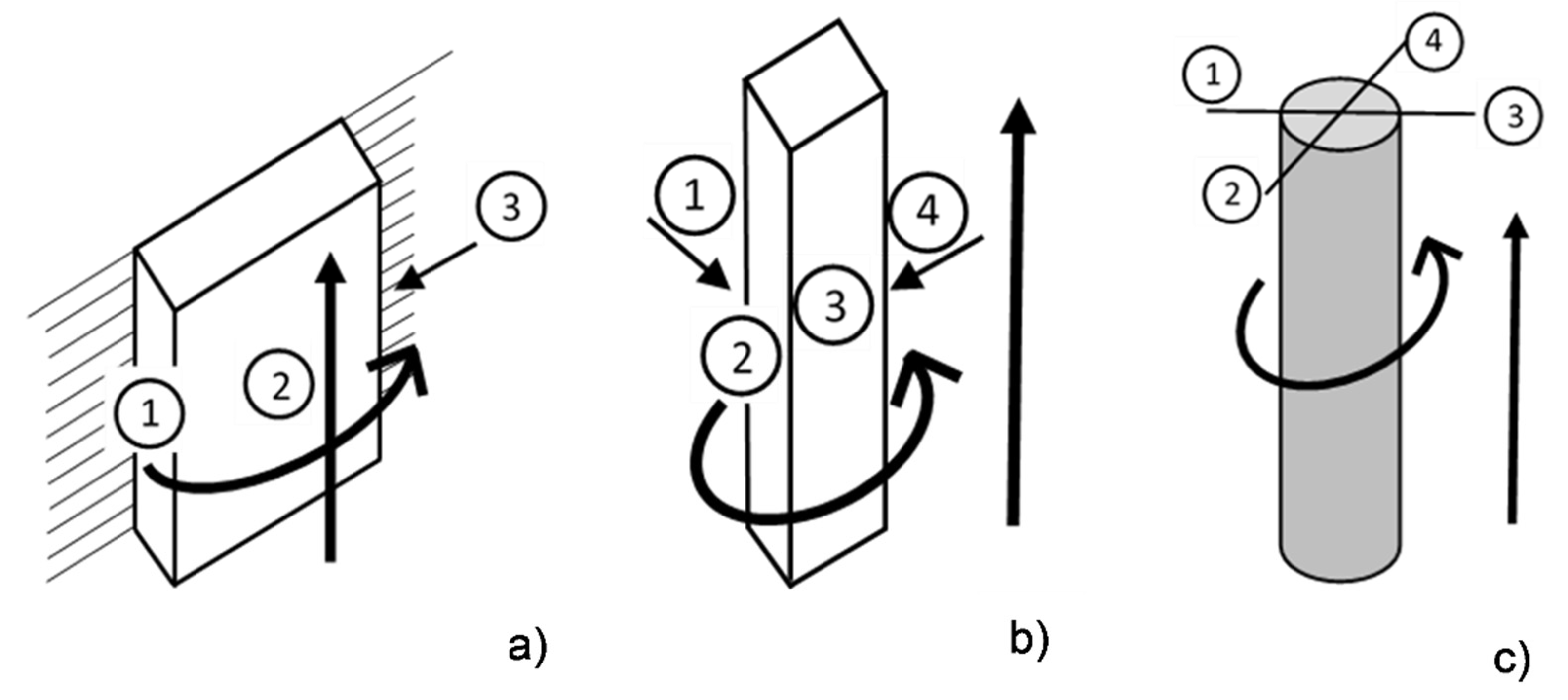
- Some structures can present anomalous tilts and displacements. Excessive displacements can put structural stability at risk.
2.2. Image Acquisition Protocol
- Before the inspection flight, it is necessary to establish a safety and security check/protocol. In this work it is followed the using steps defined by the European Union Safety Agency (EASA) https://www.easa.europa.eu/domains/civil-drones (accessed on 7 February 2022) and Specific country laws for drone flights must also be considered if applicable.
- It is recommended to carefully plan the time of the day to perform the image acquisition to get high-quality images, avoiding back-lit images, shadows, etc.
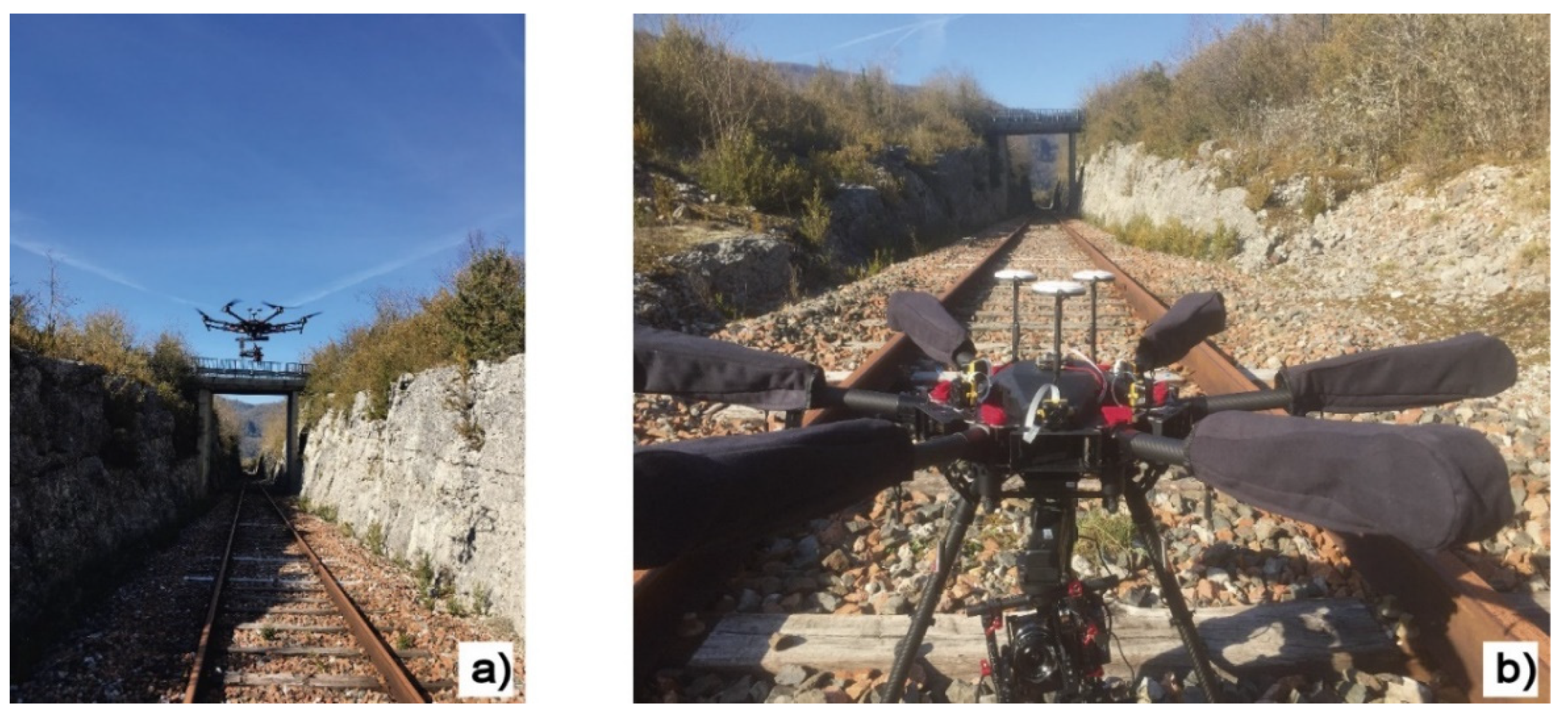
- Some parts of a bridge could be inaccessible for certain UAVs, such as the elastomeric bearing pads or the space between beams. To avoid this issue, it is recommended to combine small and large UAVs that can ensure a complete bridge inspection.
- Both laterals, top and bottom parts of the bridge should be inspected.
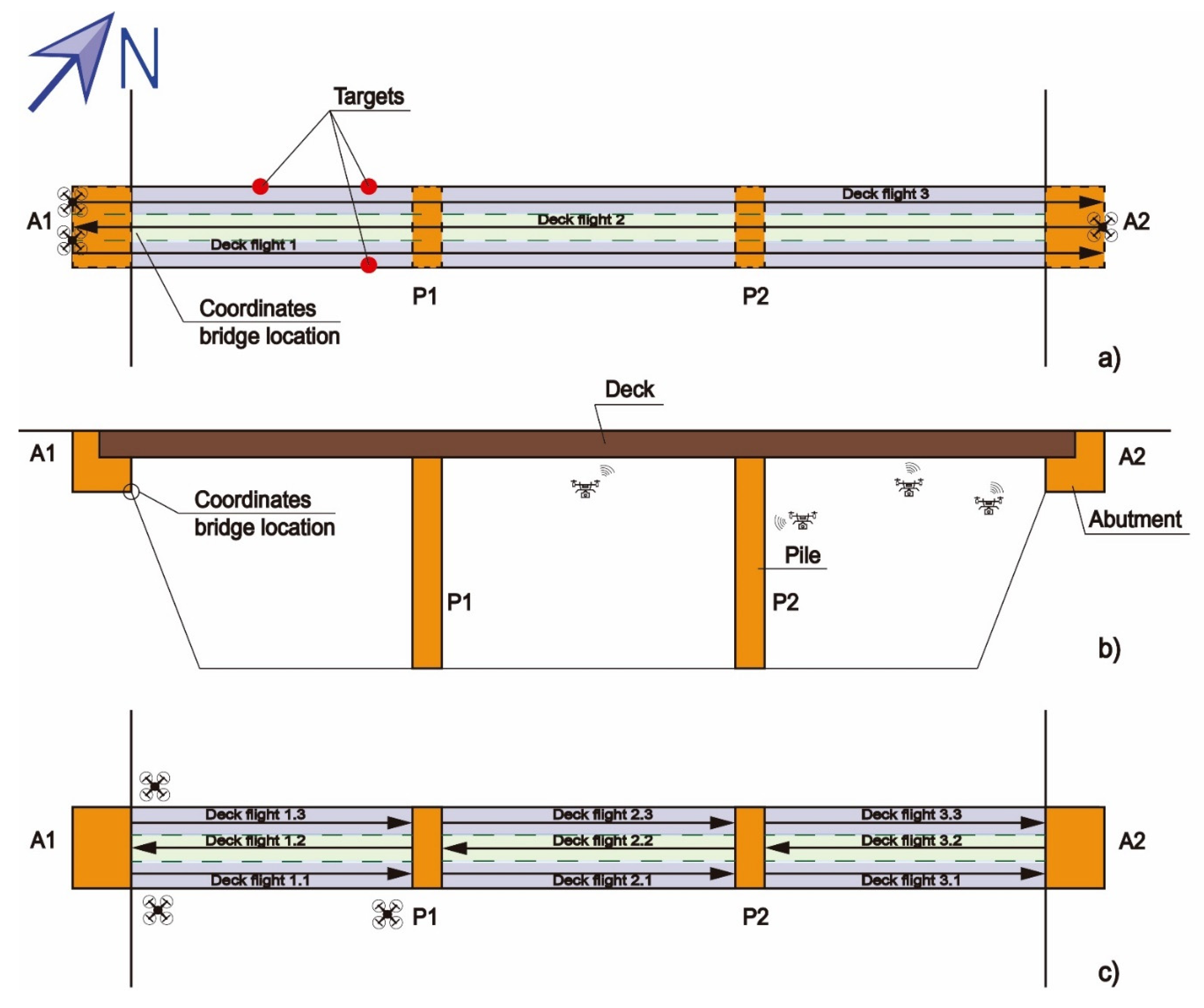
- It is recommended to systematize the order of image recording on a bridge inspection: from the first abutment to the last one, and all the intermediate columns. For example, the first abutment (A1) should be the one on the northwest. Its coordinates will determine the bridge location and the flight sequence A1-P1-P2-P3-…-Pn−1, Pn, A2 (Figure 4).
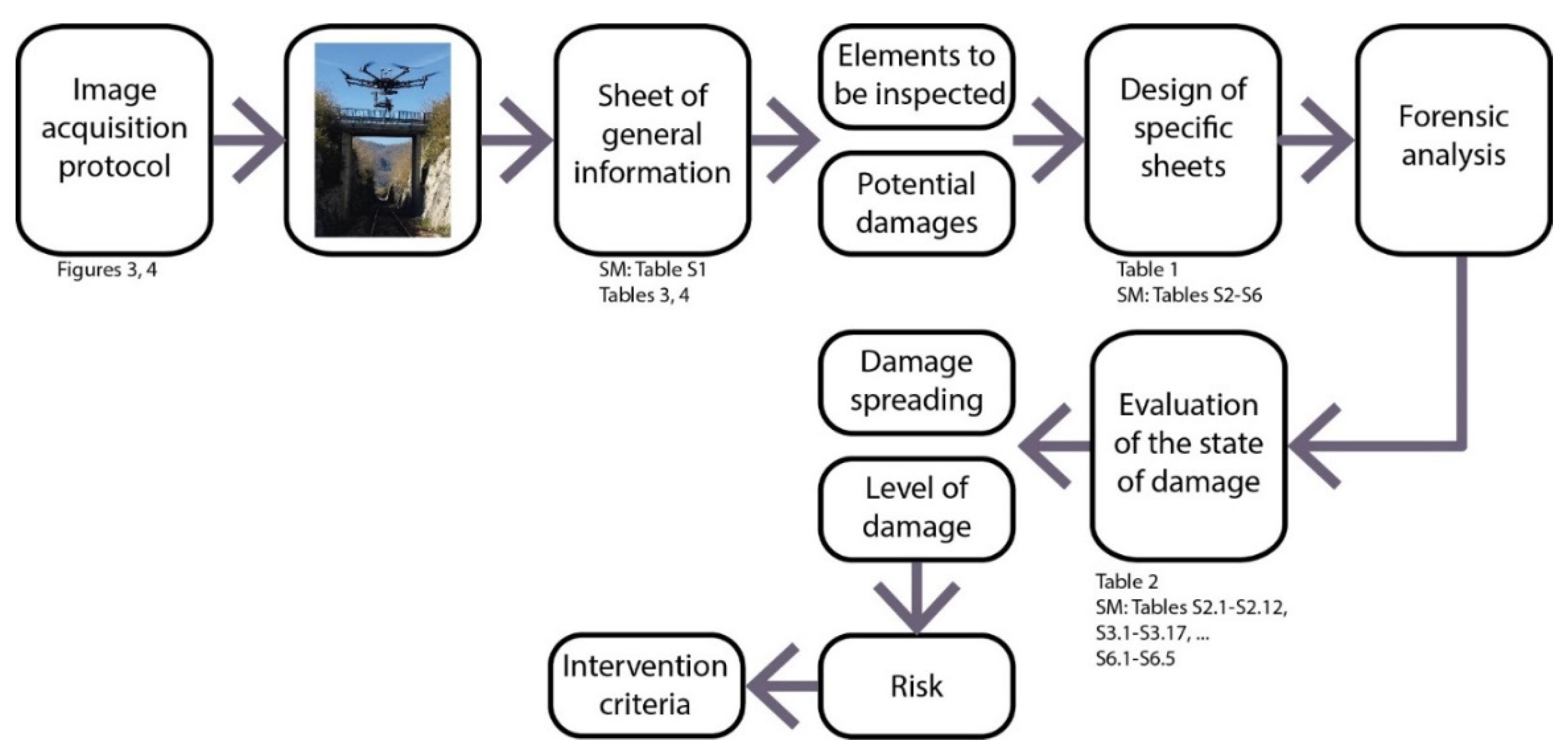
2.3. Inspections Form
2.4. Evaluation of Suggested Methodology: Case Study
3. Results
4. Discussion
5. Conclusions
Supplementary Materials
Author Contributions
Funding
Institutional Review Board Statement
Informed Consent Statement
Data Availability Statement
Conflicts of Interest
References
- The American Road & Transportation Builders Association (ARTBA). Bridge Conditions Report 2021; ARTBA: Washington, DC, USA, 2021; pp. 1–5. [Google Scholar]
- Valença, J.; Puente, I.; Júlio, E.; González-Jorge, H.; Arias-Sánchez, P. Assessment of cracks on concrete bridges using image processing supported by laser scanning survey. Constr. Build. Mater. 2017, 146, 668–678. [Google Scholar] [CrossRef]
- Riveiro, B.; González-Jorge, H.; Varela, M.; Jauregui, D.V. Validation of terrestrial laser scanning and photogrammetry techniques for the measurement of vertical underclearance and beam geometry in structural inspection of bridges. Measurement 2013, 46, 784–794. [Google Scholar] [CrossRef]
- Seo, J.; Duque, L.; Wacker, J. Drone-enabled bridge inspection methodology and application. Autom. Constr. 2018, 94, 112–126. [Google Scholar] [CrossRef]
- Teza, G.; Galgaro, A.; Moro, F. Contactless recognition of concrete surface damage from laser scanning and curvature computation. NDT E Int. 2009, 42, 240–249. [Google Scholar] [CrossRef]
- Kwiatkowski, J.; Anigacz, W.; Beben, D. A Case Study on the Noncontact Inventory of the Oldest European Cast-iron Bridge Using Terrestrial Laser Scanning and Photogrammetric Techniques. Remote Sens. 2020, 12, 2745. [Google Scholar] [CrossRef]
- Chan, B.H.J.M. Towards UAV-based bridge inspection systems: A review and an application perspective. Struct. Monit. Maint. 2015, 2, 283–300. [Google Scholar] [CrossRef]
- Koch, C.; Paal, S.G.; Rashidi, A.; Zhu, Z.; König, M.; Brilakis, I. Achievements and Challenges in Machine Vision-Based Inspection of Large Concrete Structures. Adv. Struct. Eng. 2016, 17, 303–318. [Google Scholar] [CrossRef]
- Humpe, A. Bridge Inspection with an Off-the-Shelf 360° Camera Drone. Drones 2020, 4, 67. [Google Scholar] [CrossRef]
- Hada, Y.; Nakao, M.; Yamada, M.; Kobayashi, H.; Sawasaki, N.; Yokoji, K.; Kanai, S.; Tanaka, F.; Date, H.; Pathak, S.; et al. Development of a Bridge Inspection Support System Using Two-Wheeled Multicopter and 3D Modeling Technology. J. Disaster Res. 2017, 12, 593–606. [Google Scholar] [CrossRef]
- Ivanovic, A.; Markovic, L.; Car, M.; Duvnjak, I.; Orsag, M. Towards Autonomous Bridge Inspection: Sensor Mounting Using Aerial Manipulators. Appl. Sci. 2021, 11, 8279. [Google Scholar] [CrossRef]
- Hidaka, K.; Fujimoto, D.; Sato, K. Autonomous Adaptive Flight Control of a UAV for Practical Bridge Inspection Using Multiple-Camera Image Coupling Method. J. Robot. Mechatron. 2019, 31, 845–854. [Google Scholar] [CrossRef]
- Shanthakumar, P.; Yu, K.; Singh, M.; Orevillo, J.; Bianchi, E.; Hebdon, M.; Tokekar, P. View Planning and Navigation Algorithms for Autonomous Bridge Inspection with UAVs. Springer Proc. Adv. Robot. 2018, 11, 201–210. [Google Scholar] [CrossRef] [Green Version]
- Achuthan, K.; Hay, N.; Aliyari, M.; Ayele, Y.Z. A Digital Information Model Framework for UAS-Enabled Bridge Inspection. Energies 2021, 14, 6017. [Google Scholar] [CrossRef]
- Barrile, V.; Candela, G.; Fotia, A.; Bernardo, E. UAV Survey of Bridges and Viaduct: Workflow and Application. Lect. Notes Comput. Sci. 2019, 11622 LNCS, 269–284. [Google Scholar] [CrossRef]
- Ham, Y.; Han, K.K.; Lin, J.J.; Golparvar-Fard, M. Visual monitoring of civil infrastructure systems via camera-equipped Unmanned Aerial Vehicles (UAVs): A review of related works. Vis. Eng. 2016, 4, 1. [Google Scholar] [CrossRef] [Green Version]
- Khaloo, A.; Lattanzi, D.; Cunningham, K.; Dell’Andrea, R.; Riley, M. Unmanned aerial vehicle inspection of the Placer River Trail Bridge through image-based 3D modelling. Struct. Infrastruct. Eng. 2018, 14, 124–136. [Google Scholar] [CrossRef]
- Hackl, J.; Adey, B.T.; Woźniak, M.; Schümperlin, O. Use of Unmanned Aerial Vehicle Photogrammetry to Obtain Topographical Information to Improve Bridge Risk Assessment. J. Infrastruct. Syst. 2018, 24, 04017041. [Google Scholar] [CrossRef]
- Morgenthal, G.; Hallermann, N. Quality Assessment of Unmanned Aerial Vehicle (UAV) Based Visual Inspection of Structures. Adv. Struct. Eng. 2014, 17, 289–302. [Google Scholar] [CrossRef]
- Escobar-Wolf, R.; Oommen, T.; Brooks, C.N.; Dobson, R.J.; Ahlborn, T.M. Unmanned Aerial Vehicle (UAV)-Based Assessment of Concrete Bridge Deck Delamination Using Thermal and Visible Camera Sensors: A Preliminary Analysis. Res. Nondestruct. Eval. 2018, 29, 183–198. [Google Scholar] [CrossRef]
- Agrawal, A.K.; Washer, G.; Alampalli, S.; Gong, X.; Cao, R. Evaluation of the consistency of bridge inspection quality in New York State. J. Civ. Struct. Health Monit. 2021, 11, 1393–1413. [Google Scholar] [CrossRef]
- Dorafshan, S.; Maguire, M. Bridge inspection: Human performance, unmanned aerial systems and automation. J. Civ. Struct. Health Monit. 2018, 8, 443–476. [Google Scholar] [CrossRef] [Green Version]
- Plotnikov, M.; Collura, J. Integrating Unmanned Aircraft Systems into State Department of Transportation Highway Bridge Inspection Procedures: Challenges, Implications, and Lessons Learned. Transp. Res. Rec. 2021, 2676. [Google Scholar] [CrossRef]
- Riveiro, B.; Arias, P.; Armesto, J.; Ordóñez, C. A Methodology for the Inventory of Historical Infrastructures: Documentation, Current State, and Influencing Factors. Int. J. Archit. Herit. 2011, 5, 629–646. [Google Scholar] [CrossRef]
- Rolander, D.D.; Phares, B.M.; Graybeal, B.A.; Moore, M.E.; Washer, G.A. Highway Bridge Inspection: State-of-the-Practice Survey. Transp. Res. Rec. 2001, 1749, 73–81. [Google Scholar] [CrossRef]
- Valenzuela, S.; Solminihac, H.; Echaveguren, T. Proposal of an Integrated Index for Prioritization of Bridge Maintenance. J. Bridg. Eng. 2009, 15, 337–343. [Google Scholar] [CrossRef]
- Morgenthal, G.; Hallermann, N.; Kersten, J.; Taraben, J.; Debus, P.; Helmrich, M.; Rodehorst, V. Framework for automated UAS-based structural condition assessment of bridges. Autom. Constr. 2019, 97, 77–95. [Google Scholar] [CrossRef]
- Sacks, R.; Kedar, A.; Borrmann, A.; Ma, L.; Brilakis, I.; Hüthwohl, P.; Daum, S.; Kattel, U.; Yosef, R.; Liebich, T.; et al. SeeBridge as next generation bridge inspection: Overview, Information Delivery Manual and Model View Definition. Autom. Constr. 2018, 90, 134–145. [Google Scholar] [CrossRef] [Green Version]
- Azari, H.; O’Shea, D.; Campbell, J. Application of Unmanned Aerial Systems for Bridge Inspection. Transp. Res. Rec. J. Transp. Res. Board 2021, 2676, 401–407. [Google Scholar] [CrossRef]
- Sajedi, S.O.; Liang, X. A convolutional cost-sensitive crack localization algorithm for automated and reliable RC bridge inspection. In Risk-Based Bridge Engineering: Proceedings of the 10th New York City Bridge Conference; CRC Press: Boca Raton, FL, USA, 2019; pp. 229–235. [Google Scholar] [CrossRef] [Green Version]


| Logo (If Any) | Structural Element | |||||
|---|---|---|---|---|---|---|
| Damage | Abutment | Column | Deck (or Arch) | Cables | Parapet/Handrail | Pavement |
| M1. Mortar joint degradation | X | X | X | - | X | X |
| M2. Biological growth in joints | X | X | X | - | X | X |
| M3. Stone degradation | X | X | X | - | X | X |
| M4. Efflorescence in joints | X | X | X | - | X | - |
| M5. Efflorescence in masonry stones | X | X | X | - | X | - |
| M6. Mineral precipitation in joints (speleothems) | X | X | X | - | - | - |
| M7. Lichen growth | X | X | X | - | X | X |
| M8. Loss and/or disengage of masonry stones | X | X | X | - | X | - |
| M9. Erosion or scour of columns and/or abutments | X | X | - | - | - | - |
| M10. Damp and seepage through abutments | X | - | - | - | - | - |
| M11. Displacement of the beam or the elastomeric bearing pad | X | X | - | - | - | - |
| M12. Elastomeric bearing pad degradation | X | X | - | - | - | - |
| Damage | A. Damage Spreading: | B. Level of Damage | R. Risk | IC. Intervention Criteria (Recommendation) |
|---|---|---|---|---|
| M1. Mortar joint degradation | 1. None/limited: none or some joints (<10% of the area) | 1. None/low: none or only discolouration | R1. None/low: A1/B1, A1/B2, A2/B1, A3/B1 | IC1. New regular inspection (frequency according to the age of the bridge): R1 |
| 2. Moderate: Some areas (10–50%) | 2. Moderate: weathering (the mortar looks like a sandy soil) | R2. Moderate: A1/B3, A2/B2, A3/B2 | IC2. A detailed inspection by specialized engineer is needed, with auxiliary means if necessary: R2 | |
| 3. Widespread (>50%) | 3. High/very high: disintegration of joints | R3. High/very high: A2/B3, A3/B3 | IC3. An URGENT detailed inspection by a specialised engineer is needed, with auxiliary means if necessary: R3 |
| Code: 2019/001 |  |
|---|---|
| Reference: Demonstrator bridge 1: Masonry bridge | |
| Bridge abutment 1 location (UTM coordinates) | X: 46.336143096035585 |
| Y: 5.6907070261430475 | |
Slide 1 photograph | Slide 2 photograph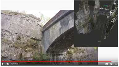 |
Top view photogram | Bottom view photogram |
| Construction date: Not available | Length of bridge: 10.8 m |
| Number of spans: 1 | Maximum height of the columns: unknown |
| Traffic on the bridge: Railway Road vehicles Mixed Pedestrian | Relevance of the upper track: Moderate Medium High |
| Lower circulation: Railway Road Natural feature: river, gorge… | Relevance of the lower track (if any): Moderate Medium High |
| Bridge abutment type Masonry Concrete Reinforced earth wall | Bridge columns (piers) type Masonry Concrete Metal Composite None |
| Bridge superstructure (deck/arch) Masonry Concrete Metal Composite | Steel cables elements Cable-stayed bridge Suspension bridges None |
| Bridge road pavement Masonry Concrete Asphalt pavement Without pavement Not available | Parapet/handrail Masonry Concrete Metal Composite None |
| Bearing Composite neoprene/steel Lead None Not available | Expansion joint: Yes None Not available |
| Wing walls Concrete Metal None | Number of bridge columns (piers): 0 |
| Code: 2019/002 | |
|---|---|
| Reference: Demonstrator bridge 2: Concrete bridge | |
| Bridge abutment 1 location (UTM coordinates) | X: 46.34248069440977 |
| Y: 5.692425433712043 | |
Slide 1 photograph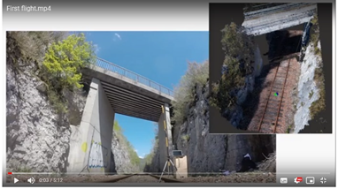 | Slide 2 photograph |
Top view photogram | Bottom view photogram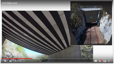 |
| Construction date: Not available | Length of bridge: 11.6 m |
| Number of spans: 3 | Maximum height of the columns: Unknown |
| Traffic on the bridge: Railway Road vehicles Mixed Pedestrian | Relevance of the upper track: Moderate Medium High |
| Lower circulation: Railway Road Natural feature: river, gorge… | Relevance of the lower track (if any): Moderate Medium High |
| Bridge abutment type Masonry Concrete Reinforced earth wall | Bridge columns (piers) type Masonry Concrete Metal Composite None |
| Bridge superstructure (deck/arch) Masonry Concrete Metal Composite | Steel cables elements Cable-stayed bridge Suspension bridges None |
| Bridge road pavement Masonry Concrete Asphalt pavement Without pavement Not available | Parapet/handrail Masonry Concrete Metal Composite None |
| Bearing Composite neoprene/steel Lead None Not available | Expansion joint: Yes None Not available |
| Wing walls Concrete Metal None | Number of bridge columns (piers): 2 |
Publisher’s Note: MDPI stays neutral with regard to jurisdictional claims in published maps and institutional affiliations. |
© 2022 by the authors. Licensee MDPI, Basel, Switzerland. This article is an open access article distributed under the terms and conditions of the Creative Commons Attribution (CC BY) license (https://creativecommons.org/licenses/by/4.0/).
Share and Cite
Cano, M.; Pastor, J.L.; Tomás, R.; Riquelme, A.; Asensio, J.L. A New Methodology for Bridge Inspections in Linear Infrastructures from Optical Images and HD Videos Obtained by UAV. Remote Sens. 2022, 14, 1244. https://doi.org/10.3390/rs14051244
Cano M, Pastor JL, Tomás R, Riquelme A, Asensio JL. A New Methodology for Bridge Inspections in Linear Infrastructures from Optical Images and HD Videos Obtained by UAV. Remote Sensing. 2022; 14(5):1244. https://doi.org/10.3390/rs14051244
Chicago/Turabian StyleCano, Miguel, José Luis Pastor, Roberto Tomás, Adrián Riquelme, and José Luis Asensio. 2022. "A New Methodology for Bridge Inspections in Linear Infrastructures from Optical Images and HD Videos Obtained by UAV" Remote Sensing 14, no. 5: 1244. https://doi.org/10.3390/rs14051244
APA StyleCano, M., Pastor, J. L., Tomás, R., Riquelme, A., & Asensio, J. L. (2022). A New Methodology for Bridge Inspections in Linear Infrastructures from Optical Images and HD Videos Obtained by UAV. Remote Sensing, 14(5), 1244. https://doi.org/10.3390/rs14051244