1. Introduction
In 2004, Fishler and others proposed the concept of Multiple input Multiple output (MIMO) radar based on the idea of spatial diversity [
1,
2,
3,
4]. Owing to the use of waveform diversity technology, MIMO radar has lots of advantages including flexible operation mode, high angle measurement accuracy, low probability of interception and strong multi-target tracking ability. The research contents in this field mainly include waveform design, beamforming, and parameter estimation [
5,
6]. In view of the defects in beam pointing of phased array radar and the contradiction between doppler ambiguity and range ambiguity, a new concept of frequency diversity array (FDA) is proposed [
7]. In recent years, the FDA system was introduced into MIMO radar, which is how the FDA-MIMO radar came into being [
8]. As a new radar system recently proposed, the FDA-MIMO radar has great advantages in parameter estimation, especially in target angle and range estimation [
9]. According to the spatial distribution of radar antennas, there are two main types of the MIMO radar: statistical MIMO radar with widely separated antennas [
10,
11] and collocated MIMO radar with close spacing antennas [
12,
13]. The research object of this paper is monostatic MIMO radar, which belongs to collocated MIMO radar.
The FDA-MIMO radar is different from the traditional array radar, and the carrier frequency of its transmitted signal is slightly different [
14]. Therefore, the phase difference of electromagnetic wave propagation of FDA-MIMO radar is related not only to the spatial angle, but also to the propagation range. In other words, the steering vector of FDA-MIMO radar signal has a two-dimensional dependence on range and angle, so it can effectively estimate the angle and range information of the target. The controllable degree of freedom (DOF) of range dimension of FDA-MIMO radar increases the flexibility of radar signal processing [
15]. It can meet the tasks of moving target detection and high-resolution radar imaging at the same time. In addition, FDA-MIMO radar can introduce more system controllable DOFs to solve the key problems faced by moving target detection of high-speed radar platform, such as range ambiguity, clutter suppression, and so on [
9]. Therefore, it is of great significance to study the target parameter estimation algorithm of FDA-MIMO radar.
The FDA-MIMO radar introduces the concept of frequency diversity on the basis of the MIMO radar. This kind of radar can make use of angle and range information of a target contained in a transmitting steering vector to solve the doppler ambiguity and range ambiguity in the traditional radar parameter estimation. Xu et al. realized the unambiguous estimation of angle and range by MLE algorithm [
16], while Chen et al. used sparse reconstruction method to estimate parameters [
17]. For the angle-range coupling problem, Wang et al. turned the transmitting array into sub-arrays, and the frequency increment between each sub-array was different [
18]. Wang et al. proposed to transmit two pulses with zero and non-zero frequency increments, respectively [
19]. There are many algorithms in MIMO radar applied to FDA-MIMO radar. In [
20,
21], the angle and range estimation of the target is achieved by the multiple signal classification (MUSIC) scheme. Owning to the spatial spectrum search process, the algorithm has large computational redundancy. To reduce the large computational redundancy caused by spatial spectrum search, many improved algorithms have been proposed. In [
22], Yan et al. proposed a two-stage estimating signal parameters via rotation invariance technique (ESPRIT) scheme for FDA-MIMO radar to achieve both range and angle estimations. To further reduce the computational redundancy, Liu et al. developed a real-valued ESPRIT scheme in [
23]. This algorithm utilizes the extended real-valued data constructed by the Centro-Hermitian property to cut down the computational redundancy.
All the above algorithms are based on well calibrated array. In other words, the above algorithms do not consider the influence of array gain-phase error [
24,
25]. Owning to the existence of gain-phase errors, the performance of many algorithms will be greatly reduced or even become invalid [
26,
27]. Unfortunately, for FDA-MIMO radar, few research work takes the impact of gain-phase error into account. For MIMO radar, many scholars have been using different methods to overcome the effect of array gain-phase error. A original ESPRIT-like method is developed in [
28], which utilizes the instrumental sensors method (ISM) to achieve the angle estimation. In [
29], an ESPRIT-based method is developed to obtain angle and gain-phase errors estimation. The ESPRIT-based algorithm first achieves the angle estimation. Then the gain-phase error is estimated subsequently. Besides subspace algorithms, the tensor-based algorithms also perform well in gain-phase error estimation. In [
30], a joint method for angle and gain-phase error estimation according to trilinear decomposition is proposed. This algorithm takes advantage of the parallel factor (PARAFAC) decomposition technique to obtain direction matrix estimation, and then estimates the angle and gain-phase error. In this work, there is no need for spatial spectrum search to realize automatically paired angle estimation. Moreover, this tensor based algorithm makes use of the multidimensional characteristics of multidimensional data and improves the performance of angle estimation. Therefore, this algorithm outperforms other subspace algorithms mentioned before. Unfortunately, there exists an error accumulation effect in the algorithm, which affects the accuracy of array gain-phase error estimation.
In this paper, aiming at the angle-range estimation problem of FDA-MIMO radar under the condition of gain-phase error, a high performance estimation algorithm is developed. The algorithm is on the basis of tensor and utilizes the multidimensional characteristics of multidimensional data. Firstly, the received data can be rewritten as a three-dimensional(3D) tensor. Then, the PARAFAC decomposition is utilized to decompose the 3D tensor to obtain the direction matrix containing the target information. After that, the direction matrix and auxiliary elements are used to track the angle of the target. Finally, the proposed algorithm takes advantage of the special properties of FDA-MIMO radar transmitting array and the angle estimation to achieve the range estimation. To remove the error accumulation influence in parameter estimation, the estimations of phase error and gain error are obtained separately. The gain error estimation is firstly achieved by the relationship between any two steering vectors and then the phase error estimation is obtained by the phase of all elements and the angle-range estimation. Since the estimation of phase error and gain error are achieved separately, the effect of each other is removed in the process of estimation. In brief, the algorithm removes the influence of error accumulation. Hence, this scheme can provide more outstanding angle-range and gain-phase error estimation performance than other algorithms.
To summarize, our contributions are as follows:
- (1)
The proposed algorithm solves the joint angle-range estimation problem of FDA-MIMO radar with array gain-phase error. A tensor-based estimation scheme that can provide superior estimation performance is developed;
- (2)
In this paper, an gain-phase error estimation method that can eliminate the influence of error accumulation is presented. The proposed algorithm can obtain more accurate gain-phase error estimation;
- (3)
In this paper, the Cramer-Rao bound (CRB) is derived for angle and range estimation and gain-phase error estimation in FDA-MIMO radar with array gain-phase error (see
Appendix A for details).
This paper can be divided into the following parts.
Section 2 expounds the signal model.
Section 3 is the target parameter estimation scheme of FDA-MIMO radar. Numerical experiments are presented in
Section 4.
Section 5 is the conclusion, and the
Appendix A is at the end of the paper.
The notations related to this paper are shown in the following
Table 1.
2. Tensor-Based Data Model
In this paper, a narrowband monostatic FDA-MIMO radar is considered. The radar array configuration is depicted in
Figure 1. The number of receiving and transmitting antennas is
N and
M, respectively. Both transmitting and receiving arrays are uniform linear arrays (ULA) with half wavelength spacing. The spacing of transmitting and receiving arrays is defined as
and
, respectively. According to the characteristics of frequency diversity, there is a small frequency increment between adjacent transmitting elements. If the first transmitting antenna is taken as the reference element, the signal carrier frequency on
m-th element can be given by [
31].
where
is the original carrier frequency of a radar.
is a well small frequency increment. Therefore, the transmitting signal on
m-th element is given by
where
E is total emission energy,
is the transmission waveform, and
T is pulse delay. Assume that the transmitting waveform satisfies orthogonality. In other words,
satisfies the following equation
Assuming that there are
K independent targets in the far field. The direction of arrival (DOA) of
k-th target is defined as
. Similarly, the range of
k-th target is given by
. The received data from the m-th antenna is given by [
16,
32]
where
is the complex-valued reflection coefficient of
k-th target,
is the time delay.
After matched filtering, the received snapshot can be written as [
33]
where
is the noise vector.
Therefore, the transmitting steering vector
can be expressed by the following formula [
34]
where
,
. The propagation velocity and wavelength of the transmitted signal are represented by
c and
, respectively. It is not difficult to find that the range and angle information are contained in transmitting steering vector. However, there exists a coupling phenomenon in the range and angle field. According to the characteristics of FDA-MIMO radar, there are differences between transmitting array and receiving array. The receiving steering vector
can be expressed as
The formula in Equation (
5) is expressed in ideal condition. The array elements are not impacted by gain-phase errors. In practice, it is impossible to calibrate all the elements accurately. Therefore, there will be gain-phase errors between array elements. Thus, the signal model with gain-phase errors is given by
where
,
.
and
are array gain-phase error matrices of transmit array and receive array, respectively, and they are both diagonal matrices. To eliminate the gain-phase error, the well-calibrated array element needs to be used. Given
m and
n well-calibrated array elements at transmitter and receiver, the first element of transmitter and receiver is set as the reference of transmitter and receiver, respectively. Therefore, the steering vector with gain-phase error is expressed as
where the space between
n-th receive array and reference array can be expressed by
. Similarly, the distance between
m-th transmit array and reference array is given by
. The definition of
and
is given by
Since the signal model is three-dimensional, the signal model can be constructed in tensor form, which is written as
where
L stand for the number of snapshots, the
-th element of the transmit direction matrix
is represented by
,
-th element of
can be expressed as
,
is the
-th element of
, while
.
is the noise matrix.
By definition, the third-order signal
is decomposed into three parts in three directions. In order to simplify the expression, the mode-3 matrix unfolding of the third-order signal
is represented by
, where
can be expressed as [
35]
where
can be given by
Similarly, in order to simplify the expression, the other two directions of the third-order signal
can be represented by
and
, where
and
can be expressed as [
35]
where
and
represent the noise matrices of the corresponding direction, respectively.
4. Simulation Results
To verify the effectiveness of the proposed method and highlight its advantages, several groups of numerical experiments are presented in this part. MUSIC method [
21], Unitary ESPRIT algorithm [
23], ESPRIT-based algorithm [
29], Li’s method [
30], and Cramer-Rao bound (CRB) (see
Appendix A for details) are used to compare with the proposed method. It is worth mentioning that the ESPRIT-based algorithm and Li’s method are for MIMO radar. In this paper, we combine the ESPRIT-based method and Li’s method with the proposed method, respectively. Then ESPRIT-based method and Li’s method are introduced into FDA-MIMO radar.
In this part, the monostatic FDA-MIMO is composed of
transmit elements and
received elements. In the simulation experiment, suppose there are
uncorrelated targets. Specifically, the positions of the three targets are
m,
m, and
m. Since the proposed algorithm is under the condition of gain-phase error, the array gain-phase error is added to the receiving and transmitting elements in the simulation. The coefficients of gain-phase error are stochastically written as:
and
. The root mean square error (RMSE) is used to evaluate the developed algorithm’s performance. The RMSEs of the angle estimation and range estimation are given by
where the
ith Monte Carlo tests of
and
can be represented by
and
, respectively. In addition, the total number of Monte Carlo tests is given by
.
For the gain-phase error estimation, the RMSE is given by
where the
ith Monte Carlo tests of
and
are written as
and
, respectively.
The probability of the successful detection (PSD) is another standard to evaluate the performance of the proposed algorithm, where PSD can be defined as
where
D is the total number of correct results. When the absolute error of a simulation result is less than
, we define it as a successful experiment.
Figure 2 and
Figure 3 show the joint estimation results of angle-range and the estimation results of gain-phase error, respectively. In this experiment, the number of snapshots
, while
. It is obvious from
Figure 2 that the developed scheme can accurately obtain the joint angle and range estimation. In addition, we can see from
Figure 3 that the gain-phase error estimation is also correct. Therefore, the two graphs testify the availability of the proposed method.
For testifying the advantages of the proposed method, several groups of numerical experiments are presented. The first set of numerical experiments shows the connection between RMSE and
in angle and range estimation. The experimental consequence are shown in
Figure 4 and
Figure 5. The number of snapshots
. The MUSIC method, the unitary ESPRIT algorithm, the ESPRIT-based algorithm, Li’s method, and CRB are used to contrast the performance with the method in this paper. From
Figure 4 and
Figure 5, we can know that the performance of the proposed algorithm is more outstanding than that of the others. It is worth mentioning that the MUSIC method and the unitary ESPRIT algorithm directly fail in the presence of gain-phase errors. It fails to obtain the correct estimations of angle and range. Most of the existing joint angle and range estimation algorithms for FDA-MIMO radar will fail in the presence of gain-phase error. In brief, the method in this paper is very meaningful. The angle and range estimation performance of this algorithm with gain-phase error is not only more outstanding than that of the others, but also closer to CRB curve, which is verified by
Figure 4 and
Figure 5. The reason why the angle and range estimation performance of the developed scheme is superior than that of the others is that the developed scheme takes advantage of multi-dimensional characteristics and retains the original structure of multidimensional data. In the data processing stage, the proposed algorithm uses more effective information.
To verify the superiority of the proposed algorithm in gain-phase error estimation, the second numerical simulations can be presented.
Figure 6 shows the performance of different algorithms for gain-phase error estimation under different
. The number of snapshots
. From the last experiment, it can be known that the MUSIC method and the unitary ESPRIT algorithm have been invalid under the condition of gain-phase error. Therefore, in this numerical experiment, the MUSIC method and the unitary ESPRIT algorithm will not be added to the comparison. From
Figure 6 we can know that the gain-phase error estimation performance of the three algorithms advances with the increase of
. However, the performance of the proposed method is obviously superior than that of Li’s method and the ESPRIT-based method. The multi-dimensional structure of data is considered in the proposed algorithm. Moreover, the gain error and the phase error are estimated separately. Thus the error accumulation effect is eliminated, which is the reason why the performance of the method in this paper is more outstanding.
The following numerical simulations can be designed to find out the effect of snapshot number on the performance of angle and range estimation with
.
Figure 7 and
Figure 8 show the influence of different snapshot numbers on angle estimation performance and range estimation performance of different methods, respectively. From
Figure 7, we can see that the angle estimation performance of the proposed method is obviously superior than that of the ESPRIT-based method when the number of snapshots is lower than 100. With the increase of the number of snapshots, the angle estimation performance of the two methods has been advanced to varying degrees. When the number of snapshots is more than 100, the angle estimation performance gap between the two algorithms is very small. However, the angle estimation performance of method in this paper is still superior to that of the ESPRIT-based algorithm, and closer to the CRB curve. In addition, the performance of the proposed algorithm is always superior to that of Li’s algorithm.
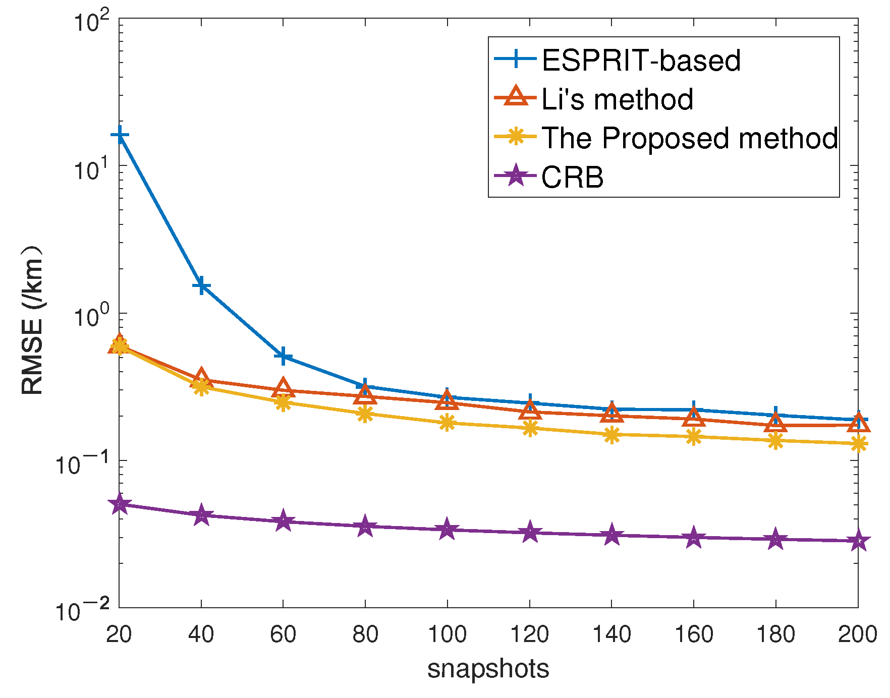
Figure 8 shows the influence of the number of snapshots on range estimation performance. According to
Figure 8, as the number of snapshots increases, the range estimation performance of both algorithms has been improved. When the number of snapshots is lower than 80, the range estimation accuracy of the proposed method is obviously superior to that of the ESPRIT-based method. When the number of snapshots is more than 80, the performance gap between the two algorithms tends to be stable, but the range estimation accuracy of the method in this paper is still significantly superior to that of the ESPRIT-based method. The performance of Li’s algorithm is at the average level of the other two algorithms. Since the proposed algorithm utilizes the multi-dimensional structure of data, its performance is obviously more outstanding than that of Li’s algorithm and the ESPRIT-based method.
The following numerical experiment is designed to demonstrate the superiority of the method in this paper for gain-phase error estimation. In this experiment,
is 20 dB. According to
Figure 9, we can see that the gain-phase error estimation accuracy of the three algorithms is improved with the increase of the number of snapshots. It is worth mentioning that the gain-phase error estimation accuracy of the method in this paper is always superior to that of the other two algorithms. The performance of the method in this paper is more stable. There are two main reasons for this. On the one hand, the proposed method takes advantage of the multi-dimensional structure and improves the gain-phase error estimation performance of the algorithm. On the other hand, the proposed algorithm eliminates the error accumulation effect in the gain-phase error estimation, so the estimation performance is not only superior but also more stable.
In this experiment, the advantage of the proposed algorithm in probability of the successful detection in angle and range estimation is demonstrated. It should be noted that the number of snapshots
.
Figure 10 and
Figure 11 represent PSD of angle estimation and range estimation of different algorithms, respectively. From the curve shown in
Figure 10, the PSD of both algorithms can reach
when
reaches 35
. The PSD of the proposed method is lower than that of Li’s algorithm when the
is less than 25
. However, the PSD of the proposed method is significantly greater than that of the other two methods when the
is more than 25
.
Figure 11 shows the advantages of the proposed method in range estimation. According to
Figure 11, we can see that the method in this paper has more significant advantages in range estimation. Under the same
, the proposed method always has more excellent PSD than the other two methods. Moreover, when the PSD of the proposed algorithm reaches
, the
is lower than that of the other two algorithms. This means that the method in this paper can perform more outstanding range estimation performance in poor environment.
The proposed algorithm also has significant advantages in gain-phase error estimation, which can be verified by following numerical experiments. In this experiment, the number of snapshots
. According to
Figure 12, we can see that the PSD of both methods augments with the rise of
, and eventually reaches
. In addition, the PSD of the proposed method can achieve
faster and the
threshold is lower. The reason why the PSD of the method in this paper is higher at the same
is that it eliminates the error accumulation effect in the gain-phase error estimation, so it can obtain more accurate gain-phase error estimation.


