Article

Multifunctional Signal Design for Measurement, Navigation and Communication Based on BOC and BPSK Modulation

1
School of Mechanical and Electrical Engineering, University of Electronic Science and Technology of China, Chengdu 611731, China
2
School of Microelectronics and Communication Engineering, Chongqing University, Chongqing 400044, China
3
Lunar Exploration and Space Engineering Center, Beijing 100190, China
4
School of Aeronautics and Astronautics, University of Electronic Science and Technology of China, Chengdu 611731, China
*
Author to whom correspondence should be addressed.
Remote Sens. 2022, 14(7), 1653; https://doi.org/10.3390/rs14071653
Submission received: 11 February 2022 / Revised: 3 March 2022 / Accepted: 23 March 2022 / Published: 30 March 2022

Abstract

:
In a multi-node spacecraft or unmanned aerial vehicle (UAV) group, a multifunctional signal containing measurement, navigation, and communication functions is required to simplify the receiver structure, and to increase spectrum utilization. The paper proposes a multifunctional signal based on a binary offset carrier (BOC) and binary phase shift keying (BPSK) modulation. The signals which carry different functions are orthogonal in the frequency domain, which causes the data transmission signal to not be affected by BOC signal. In addition, in the high carrier to noise ratio (C/N0), the spreading gain of the BOC signal ensures that the communication signal has a slight influence on navigation signals. Moreover, the multifunctional signal can achieve communication and measurement functions at the same frequency point and fast switching in multinodes. These advantages can simplify the receiver design and improve the frequency band utilization. Finally, in this study we completed the design and verification of the hardware system.

1. Introduction

At the initial stage of aerospace engineering, the measurement, navigation, and communication functions are designed independent of each other in order to obtain better performance and reduce any difficulties. With the rapid development of space technology, the numbers and types of satellites or unmanned aerial vehicles (UAV) are increasing [1]. Therefore, the requirements for measurement, navigation and high-speed communication are different from the initial stage. At present, it is hoped that these vehicles can carry more functions on the same frequency and simplify the design of the system as much as possible [2,3]. The mutually independent systems are facing problems of complex management, waste of resources, and the difficulty of effective interaction between different systems, which cannot meet the current needs of satellites and UAVs.
Ref. [4] proposes the Gaussian filtered minimum shift keying (GMSK) and Pseudo-noise (PN) code to transmit ranging signals and communication signals. These systems modulate the different signal through amplitude and phase modulation. In addition, the bit error rate of the communication signal is the same as binary phase shift keying (BPSK) modulation, ignoring the ratio of different function signal. In addition, the receiver will regenerate the local communication signal and subtract it from the receiving signal. In this way, the ranging signal can be separated from the whole receiving signal. Thus, the demodulation of GMSK + PN is complicated, and the data transmission rate is limited to 3 Mbps [5]. To simplify the receiving system and increase the data transmission rate, Unbalanced Quaternary Phase Shift Keying (UQPSK) is used to transmit ranging signals and communication signals in I and Q channels. However, UQPSK has some disadvantages, such as low frequency band utilization and significant influence on channel nonlinearity [6,7].
Betz presented binary offset carrier (BOC) modulation to improve accuracy and combat multipath propagation. The modulation has been adopted in the modernized global positioning system (GPS), Indian regional navigation satellite system (IRNSS), and Galileo satellite navigation system [8,9,10]. In the Beidou navigation system, the variant signals of BOC signals are applied to the B1, B2, and B3 frequency bands [11]. In these systems, BOC signals have better ranging accuracy, multipath interference resistance, and anti-interference performance than BPSK modulation [12,13,14]. However, since the autocorrelation function (ACF) of a BOC signal has multiple sidepeaks [15,16], the receiving process can lock to the sidepeak of the BOC signal, which results in biased pseudorange measurements.
The main problem in the BOC signal receiving process is the ambiguity caused by sidepeaks. Therefore, Julien et al. proposed the autocorrelation sidepeak cancellation technique (ASPeCT) [17,18]. The algorithm uses local PN code signals that contain subcarriers and do not contain subcarriers to perform correlation integral processing with BOC signals to achieve unambiguity acquisition. However, this method is only applicable to BOC (n, n) signals. The subcarrier phase cancellation (SCPC) presented by Ward and Lillo uses two orthogonal local codes to eliminate ambiguity [19]. Ref. [20] correlates two locally generated BOC-like signals with received signals to eliminate side peaks. Lee Y and Chong D et al. proposed an algorithm that decomposed a local signal, and correlated it with the received BOC signal separately to eliminate sidepeaks [21]. Tian. et al. proposed a decimation double-phase estimator (DDPE) tracking algorithm for BOC signals that uses a normal carrier and a subcarrier to shift upper and lower sideband signal [22]. Ref. [23] uses two-dimensional correlation to alleviate the tracking ambiguity, which is called the double estimator technique (DET). The DET consists of subcarrier correlation and code correlation. The former obtains ambiguous but accurate pseudoranges. The latter obtains less accurate pseudoranges without ambiguity, and therefore is used to resolve the ambiguity of former. In summary, the BOC signal receiving process has two strategies: the traditional BPSK-like receiving method, and reconstruction of the correlation function.
To obtain a multifunctional signal, the paper adds the BPSK signals at the central frequency point of the BOC signal. At present, the combination of BPSK and BOC modulation is mostly used for global navigation satellite system (GNSS) navigation signals. Deepak Mishra uses interplex modulation to combine three signals at the same frequency [24]. The interplex modulator forms the signal of the in-phase (I) channel and the quadrature (Q) channel signal as a constant envelope signal by phase modulation. Cahn et al. use phase-optimized constant envelope a transmission method to achieve multiplexing at the same frequency [25]. The method can finish phase modulation through optimized algorithm. However, these methods should modulate PN code on each signal to distinguish each other, and cannot achieve high-speed data transmission. He Ting and Ma Zherui propose an integrated signal based on orthogonal frequency division multiplex (OFDM) and BOC modulation [26]. The OFDM signal can accomplish high-speed data transmission, and the BOC signal achieves measurement and navigation. The power of the BOC signal is lower than the OFDM signal in order to protect the OFDM signal from interference.
The multifunctional signal has the characteristics of both a BOC signal and a central frequency functional signal. By carrying two different signals at the same frequency point, the two signals assist and optimize each other, reduce hardware complexity, and simplify transmitter design. Since a BOC signal has better anti-interference performance and Doppler tracking performance than a BPSK signal, the parameters of a BOC signal (such as the PN code offset and Doppler frequency) can assist the carrier synchronization and bit synchronization of a BPSK signal. In addition, the BOC + BPSK multifunctional signal is suitable for fast switching and communication in spacecraft formation and UAV groups.
The outline of the remainder of this paper is as follows. First, the composite signals are designed in Section 2. The design of the receiving and multinode fast switching algorithm of the composite signal are described in Section 3. The application scenarios and performance analysis of the system are given in Section 4. In Section 5 and Section 6, we provide the discussion and conclusion of the composite signal, respectively.

2. The Transmitting and Receiving System of the Composite Signal

In this section, we will give a signal model of the composite signal, and introduce the structure of the transmitting and receiving system.

2.1. Signal Model

The composite BOC signal has two parts: a BOC signal and a BPSK signal. The main idea of BOC modulation is to modulate the square wave subcarrier on the spread spectrum modulation so that the power spectrum of the signal is moved to both sides of the central frequency point [27,28]. In addition, we need to insert the BPSK signal at the central frequency to achieve data transmission. Mathematically, the composite BOC signal can be expressed as Equation (1):
s t ( t ) = s BOC ( t ) + s BPSK ( t ) = α d ( t ) c ( t ) s i g n [ cos ( 2 π f s t ) ] + β b ( t )
where d ( t ) is the navigation data, c ( t ) represents the PN sequence, s i g n ( · ) is the symbolic function, and f s is the frequency of the square wave subcarrier. b ( t ) is the communication data. In addition, α and β are the signal power of the BOC signal and BPSK signal, respectively. These values indicate the proportion of BOC and BPSK signals in the whole transmitted signal. The chosen α and β are explained in Section 4. c ( t ) and b ( t ) can be expressed as Equations (2) and (3):
c ( t ) = k = α k p T c ( t k 1 f s )
b ( t ) = l = α l p T b ( t k 1 f s )
α k = ± 1 and α l ± 1 . p T c is the PN sequence, and p T b is the communication data. f s is the bandwidth, which is equal to the frequency of the subcarrier.
The received analog intermediate frequency (IF) composite signal at the wideband ADC input can be expressed as Equation (4):
s r ( t ) = s BOC ( t ) + s BPSK ( t ) + n ( t ) = α d ( t τ ) c ( t τ ) s i g n [ cos ( 2 π f s ( t τ ) ) ] e [ j 2 π ( f IF + f d ) ( t τ ) ] ( α + β = 1 ) + β b ( t τ ) e [ j 2 π ( f IF + f d ) ( t τ ) ] + n ( t )
where f IF is the IF carrier frequency, f s represents the subcarrier frequency in the receiving end, and τ is the time delay.
The paper uses BOCcos(5,5) and BPSK(5) to form the composite signal. The power spectrum with f IF = 20   MHz is shown in Figure 1. The bandwidth of BPSK and PN and the frequency of the subcarrier in the system are 5.115 MHz. The signal power spectra of the BOCcos(5,5) signal, BPSK(5) signal, and composite signal are shown in Figure 2. When the multifunctional signal is buried in noise, such as the GNSS signals, the communication data cannot be demodulated. However, in inter-spacecraft or inter-UAV communication, the signals are well above the noise floor. Thus, we ignore the case when the signal is buried in noise.

2.2. The Reception of the Composite Signal

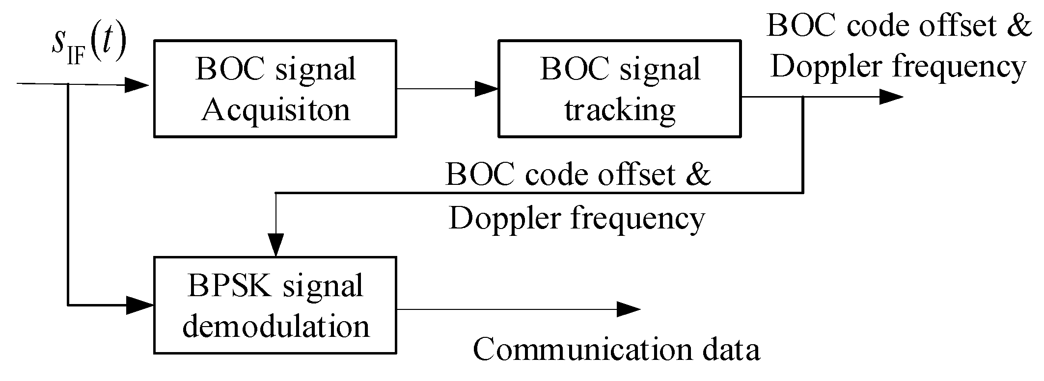
The receiving process of the composite signal is shown in Figure 3. The reception of the BOC signal is divided into two processes: acquisition and tracking. Acquisition realizes the rough estimation of the BOC signal PN code offset and Doppler frequency, and tracking achieves high accuracy estimation of the BOC signal parameters.
Since the BOC signal and the BPSK signal are at the same frequency, the two signals have the same Doppler frequency. In addition, the BOC signal has better anti-interference performance due to the use of a PN code. Therefore, we use the parameter of the BOC signal to assist the demodulation of the BPSK signal in Section 3.

3. The Receiving Process of the Composite Signal

In this section, we present the receiving process of the BOC signal and BPSK signal. First, we show that BPSK signal and BOC signal interfere with each other in the case of spectrum aliasing. Then, we design the receiving system of the composite signal. Finally, the application scenario is proposed.

3.1. The Receiving Independence of a BOC Signal and BPSK Signal

The code offset and Doppler frequency of a BOC signal are obtained through correlation between the received signal and the locally generated BOC signal. The correlation function ignoring the noise is as shown in Equation (5).
R ( t , t + τ ) = E ( s r ( t ) s BOC ( t + τ ) ) = E ( ( s BOC ( t ) + s BPSK ( t ) ) s BOC ( t + τ ) ) = E ( s BOC ( t ) s BOC ( t + τ ) + s BPSK ( t ) s BOC ( t + τ ) ) = α R BOC ( τ ) + β R BOC , BPSK ( τ )
Here, s r ( t ) represents the receiving signal in the IF frequency, and s BOC ( t ) is the locally generated BOC signal. R BOC ( τ ) is the autocorrelation function of the BOC signal. R BPSK ( τ ) is the cross-correlation function of the BOC signal and BPSK signal. R BOC ( τ ) is 30 dB higher than R BOC , BPSK ( τ ) when α = β . Therefore, the latter has little effect on the reception of the BOC signal.
The correlation function of the BOC signal and BPSK signal within a chip can be expressed as Equation (6):
0 T s s BPSK ( t ) s BOC ( t τ ) d t = 0 T s b ( t ) d ( t τ ) c ( t τ ) s i g n [ cos ( 2 π f s ( t τ ) ) ] d t
where T s = 1 f s is the width of a chip. Assuming that b ( t ) , d ( t τ ) and c ( t τ ) do not change signs during T s , the left side of Equation (6) is equal to zero, which shows that s BOC ( t ) and s BPSK ( t ) are orthogonal to each other. Therefore, after ignoring the influence of the Doppler frequency, we integrate the signal in a chip period, as in Equation (7).
0 T s s r ( t ) d t = 0 T s α d ( t τ ) c ( t τ ) s i g n [ cos ( 2 π f s ( t τ ) ) ] d t + 0 T s β b ( t τ ) d t
The first term on the right side of Equation (7) is equal to zero under ideal conditions. Thus, the demodulation of the BPSK signal is not affected by the BOC signal.

3.2. The Tracking Process of a BOC Signal

The reception of a BOC signal is divided into two processes: acquisition and tracking. Acquisition realizes the rough estimation of the BOC signal PN code offset and Doppler frequency, and tracking achieves the high accuracy estimation of BOC signal parameters. The acquisition method used in this composite signal is the same as the traditional BOC signal acquisition method [27], which is not discussed here. After obtaining the rough estimations of the code offset and Doppler offset, the system inserts the two values into the tracking system for high accuracy estimation. Figure 4 shows the structure of tracking loop.
The tracking loop is composed of a carrier tracking loop, code tracking loop, and subcarrier tracking loop. In addition, the numerically controlled oscillator (NCO) generates the local carrier according to the tracking discriminator. The carrier tracking loop adopts the second-order frequency locked loop (FLL) to assist the third-order phase locked loop (PLL), which has excellent performance under high dynamic conditions. The loop can track the frequency and phase of the carrier [29,30]. The phase discriminators of the FLL and PLL are shown in Equations (8) and (9), respectively:
e f k = a tan 2 ( C r o s s , D o t )
e p k = a tan ( Q p s , I p s )
where C r o s s and D o t are the cross product and dot product of the I channel and Q channel, respectively. Q p s is the integration result of the Q channel, and I p s is the integration result of the I channel.
The code tracking loop adopts the delay locked loop (DLL), which achieves synchronization between the PN code offset generated locally and the received signal. Its inputs are the integration and accumulation results of the early, prompt, and delay channel data of the I and Q channels [31]. The interval between the three channels is a half chip. In addition, the discriminator is shown in Equation (10):
e c k = [ I e s ( k ) I l s ( k ) ] I p s ( k ) + [ Q e s ( k ) Q l s ( k ) ] Q p s ( k ) I p s 2 ( k ) + Q p s 2 ( k )
where I e s , I p s , and I l s are the integration and accumulation results of the I channel delay, prompt, and early code, respectively. In addition, Q e s , Q p s , and Q l s are the integration and accumulation results of the Q channel delay, prompt, and early code, respectively.
The subcarrier code tracking loop has the same DLL structure, and is named the subcarrier delay locked loop (SDLL) [32]. The loop achieves synchronization between the local subcarrier and the received subcarrier. However, the inputs of the SDLL are the integration and accumulation results of early, prompt, delay channel data of subcarriers.

3.3. The Tracking Process of a BPSK Signal
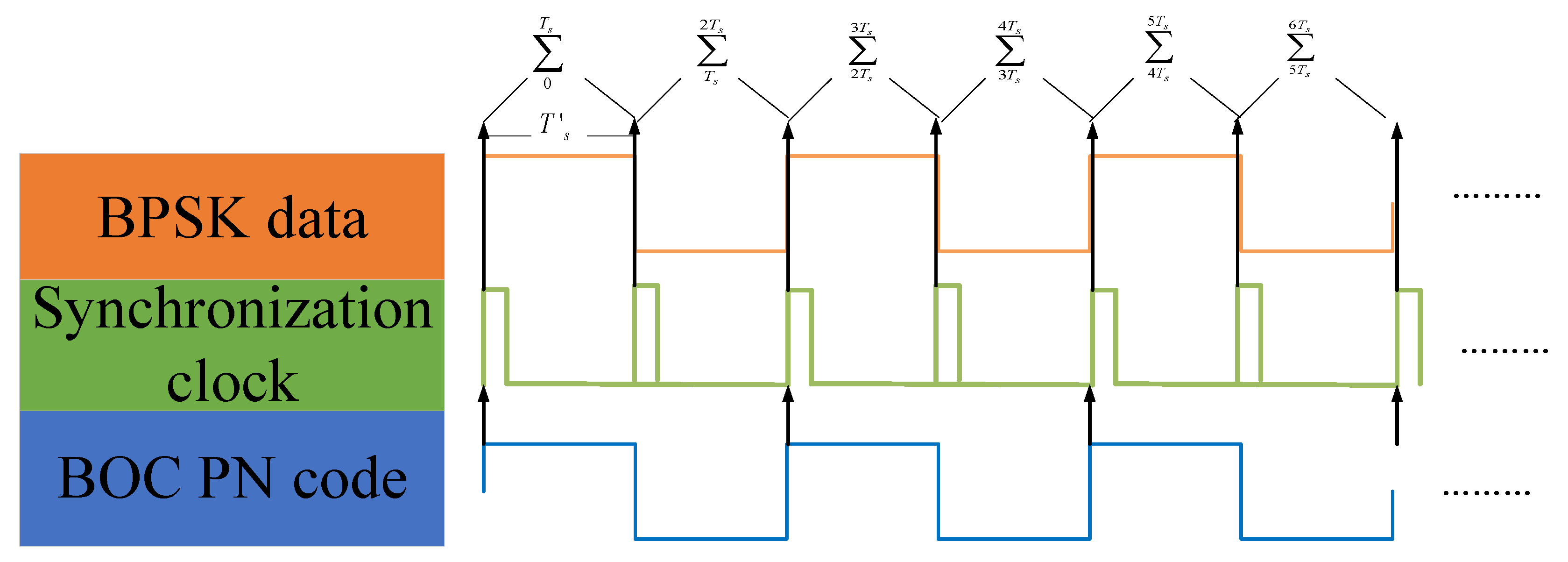
In the tracking system, we obtain the Doppler frequency and code tracking results of a BOC signal. A BOC signal and BPSK signal have the same carrier frequency and phase. Therefore, the carrier tracking results of Section 3.2 can be used by BPSK demodulation. For the bit synchronization of the BPSK signal, since the frequency of the PN code in the BOC signal at the transmitting end is the same as the chip rate of the BPSK signal, the chip lengths of the two received signals are equal without the Doppler frequency. However, the code frequency will change due to the influence of the Doppler frequency. The PN code frequency and Doppler frequency are shown in Equations (11) and (12), respectively.
f PNcode ( t ) = λ f RF ( t ) = f PNcode + λ f d ( t )
f RF ( t ) = f RF + f d ( t )
where f PNcode ( t ) and f RF ( t ) are the PN code frequency and radio frequency (RF) at time t , respectively. f PNcode and f RF represent the PN code frequency and RF without the influence of the Doppler frequency, respectively. λ = f PNcode f RF = f PNcode ( t ) f RF ( t ) is the ratio of the chip rate to RF output frequency.
The chip rate f BPSKcode ( t ) of the BPSK signal at time t is shown in (13):
f BPSKcode ( t ) = λ B f RF ( t ) = f BPSKcode + λ B f d ( t )
Here, f BPSKcode is the chip rate of the BPSK signal without Doppler influence. λ B = f BPSKcode f RF = f BPSKcode ( t ) f RF ( t ) represents the ratio of the BPSK chip rate to the RF output frequency. According to (11–13), when f BPSKcode = f PNcode , the PN code frequency is also equal to the BPSK chip rate when the Doppler frequency exists. Therefore, the chip offset of the BOC signal is the same as that of the BPSK signal. This means that we can simplify the bit synchronization process of the BPSK signal by using the bit synchronization clock of the BOC signal.
The time flow is shown in Figure 5. The DLL of the BOC signal outputs the bit synchronization clock, which assists the demodulation of the BPSK signal. In addition, the signal is accumulated according to the synchronization clock and Equation (14), and the resulting symbol is the communication data in the BPSK signal.
b ( n ) = w = ( n 1 ) T s n T s s r ( w )
Here, s r ( · ) is the BPSK signal. T s is the interval of the synchronization clock.
Figure 5. Bit synchronization and demodulation of the BPSK signal.
Remotesensing 14 01653 g005

3.4. The Application Scenario

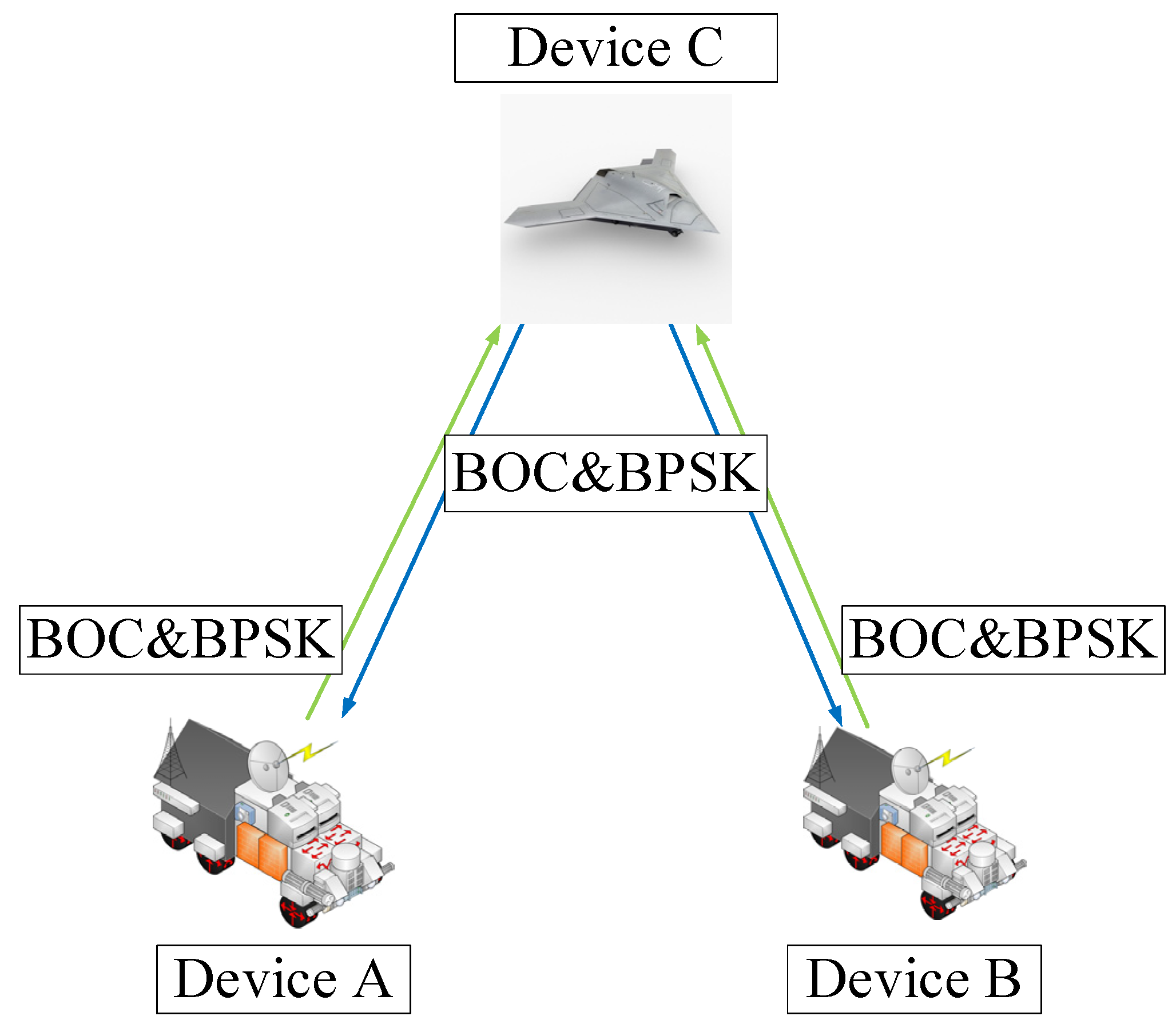
In addition to saving spectrum resources, the composite signal can also be suitable for highly dynamic communication under spacecraft formation or UAVs. The paper uses Figure 6 as an application scenario to explain this. In the scenario, the spacecraft or UAVs are replaced by different devices.
Device C is the master device that can continuously transmit composite signals to slave device A and device B. In addition, devices A and B send two different BOC signals to device C, which are used to distinguish the two devices. In addition, the BPSK signal of the uplinks are controlled of device C. When the communication target of device C is switched from A to B, the chip offset and Doppler frequency of the BOC signal are resynchronized to the BPSK demodulation module. In this way, slave devices switch in a clock cycle without the Doppler frequency search process, even under highly dynamic conditions.
In the system, we use three different PN codes in BOC signals to differentiate between devices A, B, and C. However, in the code division multiple access (CDMA) system, the near-far problem will cause the cross-correlation interference of different spacecraft. To prevent the interference of near spacecraft, we adopt the regenerative BOC signal to suppress the influence of near-far effect [33]. In the algorithm, the receiver will regenerate the BOC signal of near spacecraft with same frequency and phase through tracking loop. Then, the receiver subtracts the regenerative signal from the received signal, and obtains the transmitting signal of far spacecraft without interference.

3.5. The Fast Switching of the Composite Signal

The switching at different devices will cause a frequent loss of locked communication links. When the change rate of the Doppler Frequency is small, the out-of-lock process has little effect on data demodulation. However, if the Doppler frequency changes drastically, the communication link cannot be locked, and the data cannot be demodulated.
To solve this problem, the novel composite signal using the parameter of the BOC signal assists the retracking of the BPSK signal, which only costs one clock cycle.
There are two preconditions:
(1)
The BOC signal is continuously transmitted; and
(2)
The transmission of uplink BPSK signals is controlled by the master device.
The steps of the fast-switching algorithm are as follows.
In Figure 7, we propose the control flow of the master device to the slave device. First, master control device A transmits the BPSK signal; then, before switching, it controls device A to stop transmitting the BPSK signal using the transmission stop frame. Then, master device control device B transmits the BPSK signal.
  • The master device starts communication with device A. The links contain the BOC signal and BPSK signal.
  • Before switching, device C transmits one frame of data to control device A to stop transmitting the BPSK signal. In addition, the frame can control device B to start transmitting the BPSK signal to device C.
  • Master device C uses the code offset and Doppler frequency in the BOC signal of device B to demodulate the BPSK signal from device B.
  • If master device C needs to communicate with device A, the process is the same as steps 2 and step 3.
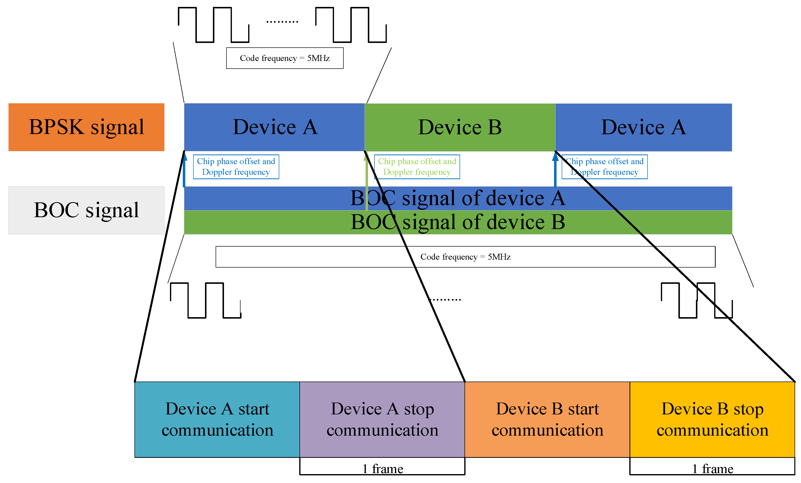
Figure 7. The time sequence of device C in the fast-switching process.
Remotesensing 14 01653 g007

4. Performance Analysis of the BOC Signal and BPSK Signal

In this section, we investigate the performance of the composite signal in terms of the acquisition time, tracking performance, bit error ratio (BER), and switching time for different ratios of BOC and BPSK signals. In addition, we will give the hardware implementation of the novel BOC signal.

4.1. The Design of the Signal Channel

The parameters of the simulation scenario are given in Table 1. We simulate the state of the nodes under very high frequency (VHF) and S-band conditions.

4.2. Acquisition Performance of the BOC Signal

For the receiver of the traditional multinode switching, the switching process will be accompanied by signal reacquisition and retracking. According to [34], the BOC signal acquisition process and the clock cycles required in each stage are shown in Figure 8. Thus, all clock cycles of one acquisition are shown in Equation (15):
T acq = T code + T FFT + T IFFT + T mul + T max + Δ t
where T code represents the PN code period. T FFT and T IFFT are the time costs of the fast Fourier transform (FFT) and inverse fast Fourier transform (IFFT) with 4096 points, respectively. T mul is the time cost to multiply the FFT results of the local PN code and the FFT results of the receiving signal. T max represents the time cost to search for the maximum value of the IFFT process. Δ t is the time cost in other processes, which is less than 100 clock cycles. The system adopts f s = 80   MHz , and the time of one acquisition is 0.6 ms.
Since a single acquisition will increase false alarms and missed alarms, the receiver uses multiple detections to increase the acquisition success probability. For the Tong detector, the minimum detection times is 6 times. In addition, the Doppler frequency caused by relative motion is less than 12 kHz. In addition, we should search the Doppler frequency using 500 Hz intervals. Based on these parameters, the acquisition time when switching devices requires T a c q _ t o t a l = 12,000   Hz × 2 500   Hz × 6 × T a c q = 172.8   ms . The total switching time is T a c q _ t o t a l + T t r a c k _ l o c k , where T t r a c k _ l o c k is the time of PLL lock time. However, the novel composite signal can ignore T a c q _ t o t a l , which saves switching time. Furthermore, the T t r a c k _ l o c k of the novel system is the same as that of the traditional system.
Figure 9 shows the single acquisition success probability under different BOC and BPSK power ratio Monte Carlo simulations. When the ratio of α and β is greater than 0.3:0.7, the main factor for the reduction of the acquisition probability is the reduction of the proportion of BOC signal power in the composite signal. When the ratio of α and β is less than 0.3:0.7, the power of the BPSK signal will interfere with the acquisition of the BOC signal. Therefore, if the system is in a low carrier-to-noise (C/N0) environment, it is reasonable to use α : β = 0.3 : 0.7 . However, when the C/N0 is higher than 70 dB-Hz, the power of the BOC signal can be reduced to improve communication performance.

4.3. Tracking Performance for the BOC Signal

The tracking performance of the BOC signal is mainly reflected in the ranging error and velocity measurement error. The ranging result error of the code tracking loop is shown in Equation (16):
σ DLL = [ d · B D F 2 · C / N 0 ( 1 + 1 T c o h · C / N 0 ) ] 0.5 · λ c
Here, λ c represents the wavelength of the BOC signal. B D F is the bandwidth of the code tracking loop. C/N0 is the carrier-to-noise ratio of the BOC signal. d represents the chip interval of the delay locked loop (DLL). T c o h represents the integration time [35].
The velocity measurement error can be equivalent to the Doppler frequency measurement error, which is determined by the third-order phase locked loop (PLL) in the system. The dynamic stress error and thermal noise jitter error of the third-order PLL are shown in (17):
σ PLL = σ t PLL + 1 3 θ e = [ B P F C / N 0 ( 1 + 1 2 T c o h · C / N 0 ) ] 0.5 + f 2 π 3 ( 1.2 B P F ) 3
The Doppler frequency can be calculated as (18).
σ Doppler = 2 σ PLL 2 π · Δ t
Here, σ t PLL represents the thermal noise jitter error, and θ e represents the dynamic stress error. B P F is the bandwidth of the PLL. f ¨ is the system acceleration. Δ t is the refresh interval time of the Doppler measurement, which is equal to 0.2 ms in the system [36,37].
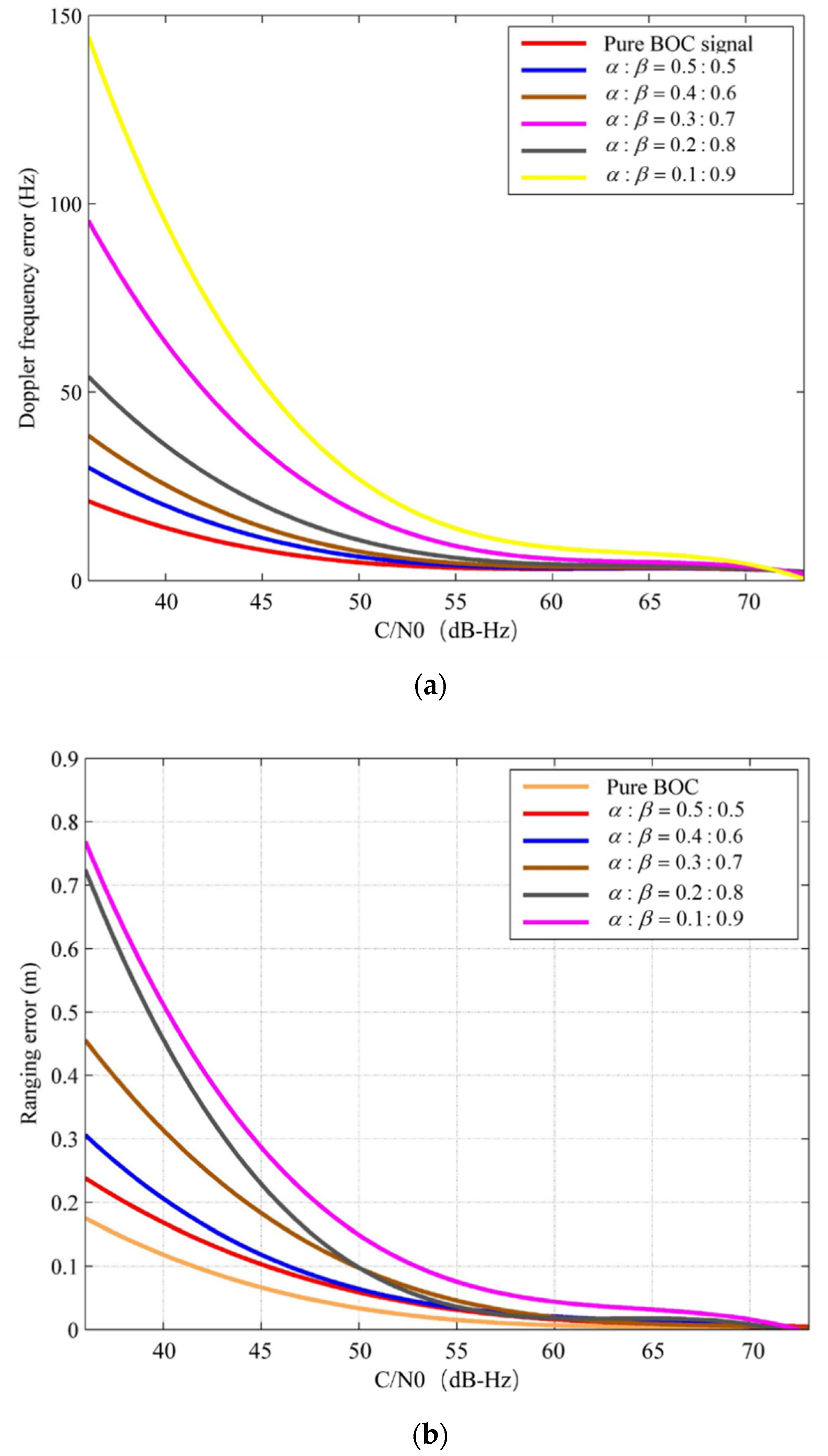
Figure 10 shows the Doppler frequency measurement error and ranging error of the composite signal under different combination modes of BOC and BPSK signals through Monte Carlo simulation. When α : β 0.3 : 0.7 , the degradation of the Doppler measurement performance is mainly due to the reduction in the power occupied by the BOC signal in the composite signal. In addition, when α : β < 0.3 : 0.7 , the improvement of the BPSK signal power will reduce the ranging and Doppler frequency measurement performance. However, when the C/N0 is higher than 65 dB-Hz, the performance of the BOC signal has the approximate measurement performance of the pure BOC signal, even if the power of the BOC signal only occupies 10% of the composite signal.

4.4. Data Demodulation with Diffferent BOC and BPSK Ratios

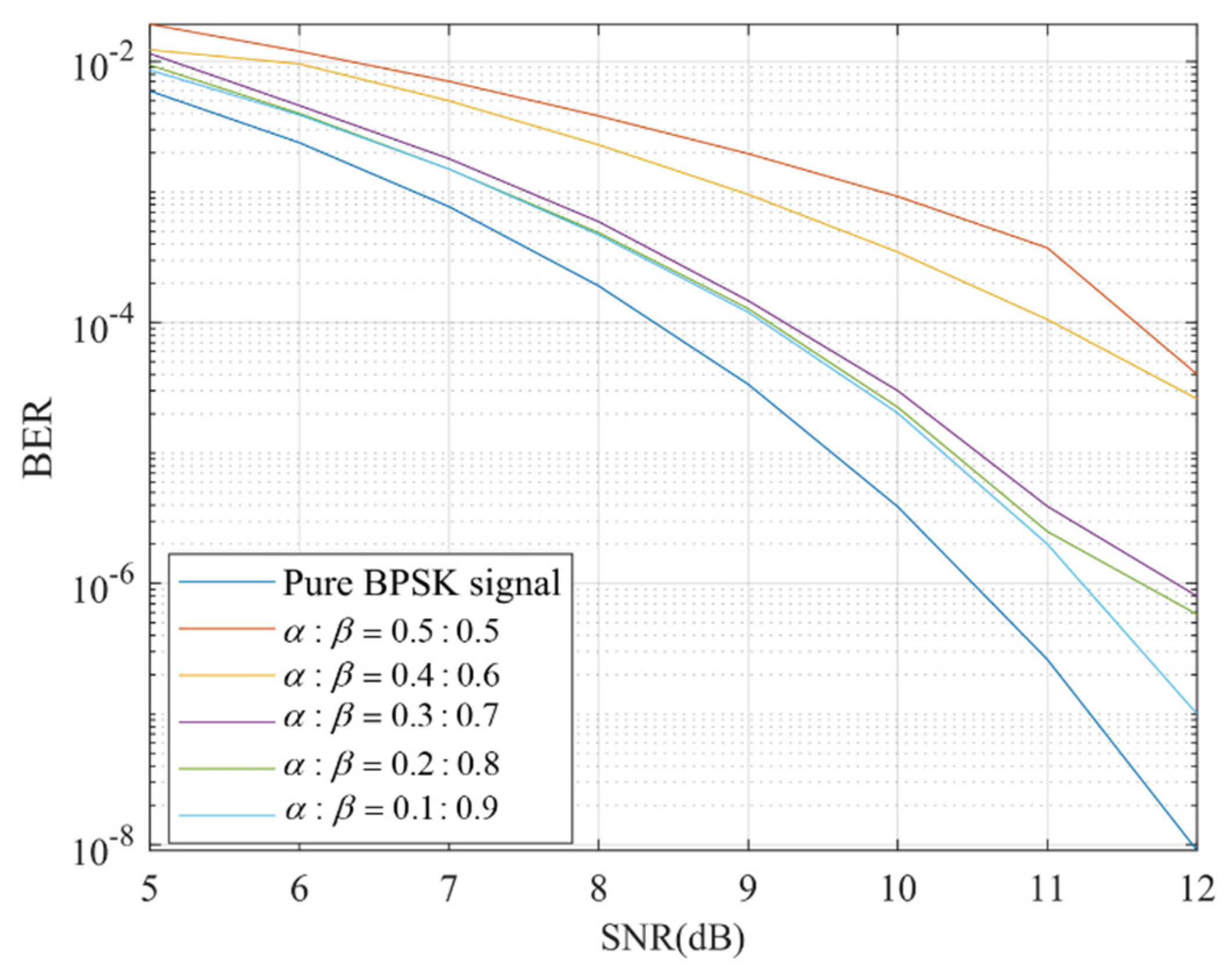
According to Equation (6), the communication signal and the BOC signal are orthogonal in the time domain. Therefore, as long as the chip accumulation time of the BPSK signal is the length of one chip of the BOC signal, the BOC signal cannot affect the demodulation of the BPSK signal. The bit error ratios (BERs) of the BPSK signal at different SNRs and ratios are shown in Figure 11. This shows that the demodulation of the BPSK signal is only influenced by the BPSK signal power in the composite signal. When the proportion of the BPSK signal in the composite signal is 50%, the signal power needs 3 dB more than the pure BPSK signal to meet the same BER.

4.5. The Performance of the Fast Switching Algorithm

The system requires fast switching among different devices. The simulation scenario is designed as follows:
(1)
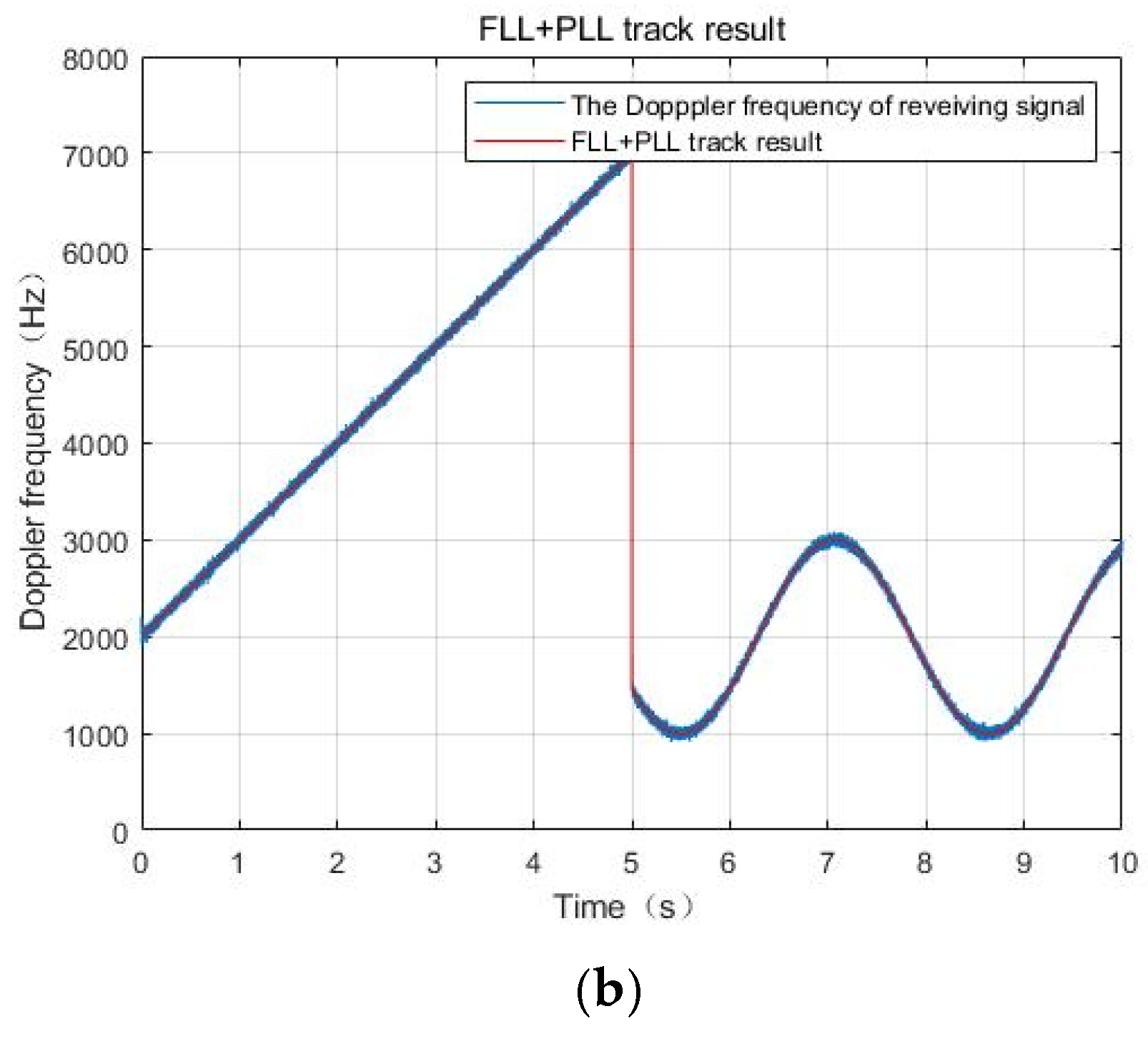
Device A performs uniform acceleration;
(2)
Device B performs sinusoidal motion; and
(3)
In the fifth second, the device communicates with the master device from A to B.
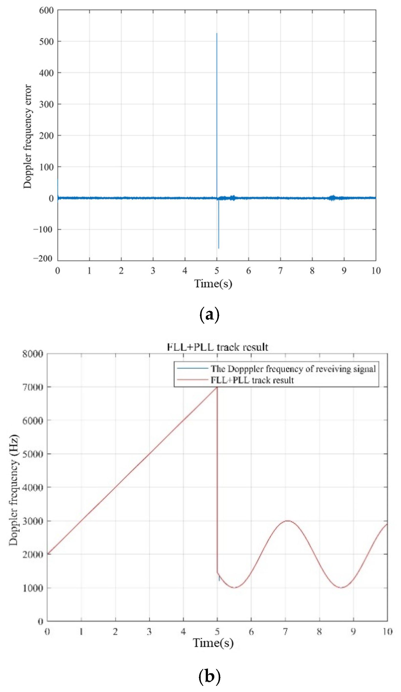
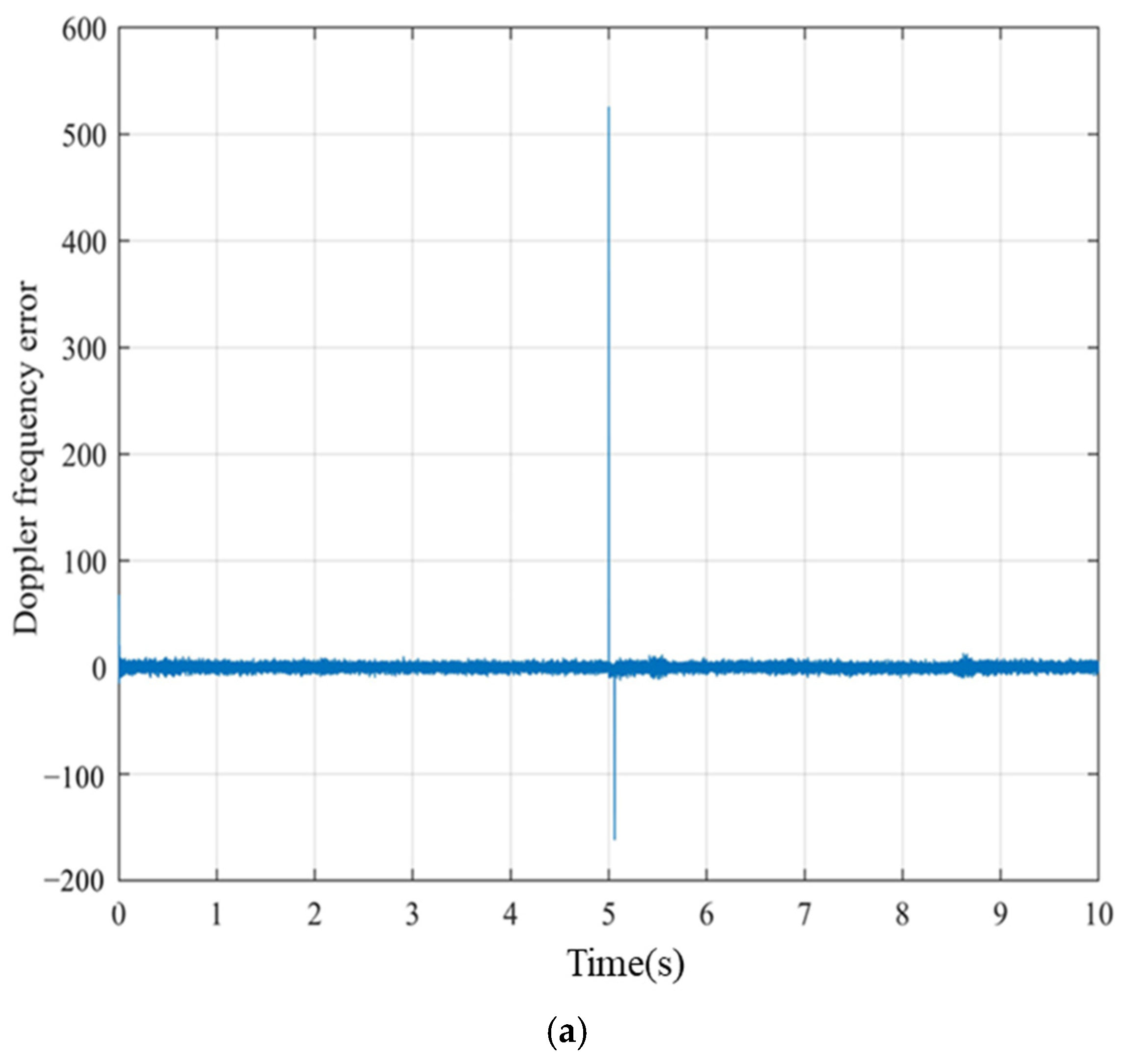
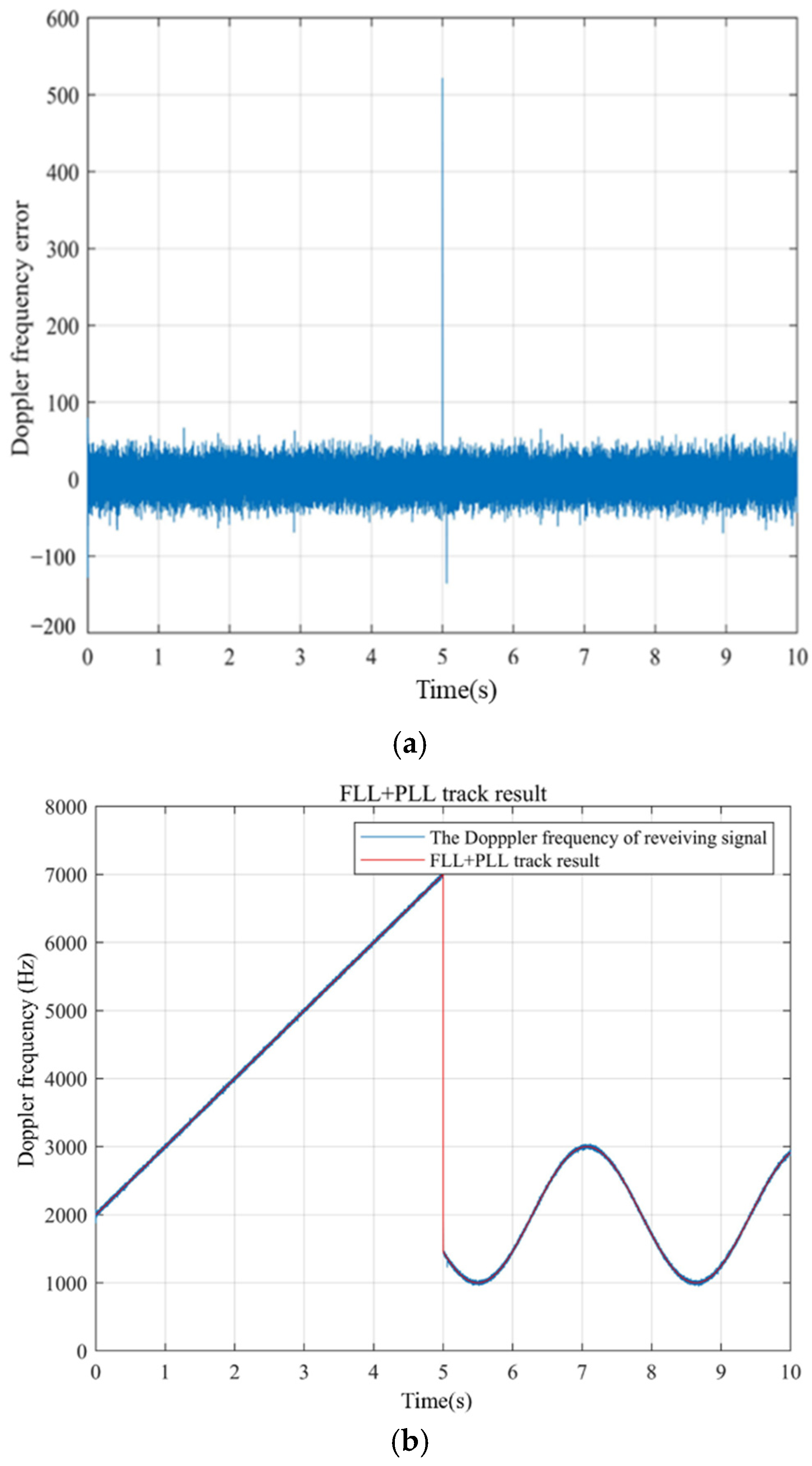
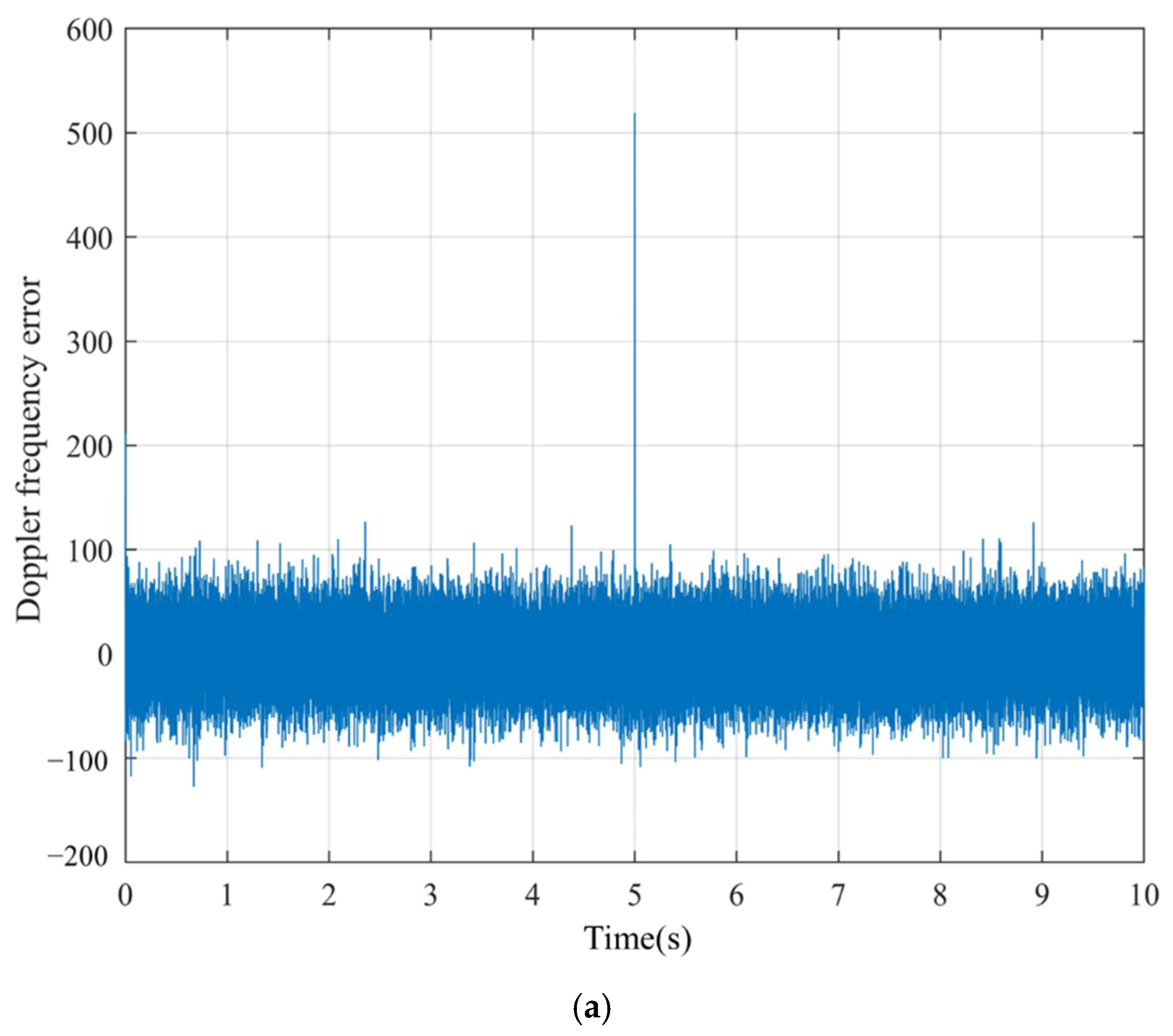
Figure 12, Figure 13 and Figure 14 show the switching time when C/N0 = 65 dB-Hz at different BOC and BPSK ratios. Furthermore, Figure 15 and Figure 16 show the switching times when α : β = 0.1 : 0.9 at different C/N0s. The simulations show that the switching time is 0.1 s in different situations. However, the switching time in software display is constrained by data refresh rate. In the hardware which we designed, we adopted 80 MHz as the sampling rate of hardware. Considering that synchronization of the reacquisition results with each module will cost 10 clock cycles, the whole requisition time is (1 + 10)/80 × 106 = 1.375 × 10⁻⁷ s.

4.6. The Hardware Application and Test
The hardware structure uses AD9361 and XC7Z020 as the transmitter and receiver, as shown in Figure 17a. The RF frequency point of the system can be any frequency point in the range of 200 MHz to ~6 GHz. In addition, we add the Doppler frequency, signal attenuation, and signal delay to the signal through the channel simulator, which is shown in Figure 17b, so as to better simulate the real environment. Some hardware test results are shown in Table 2.
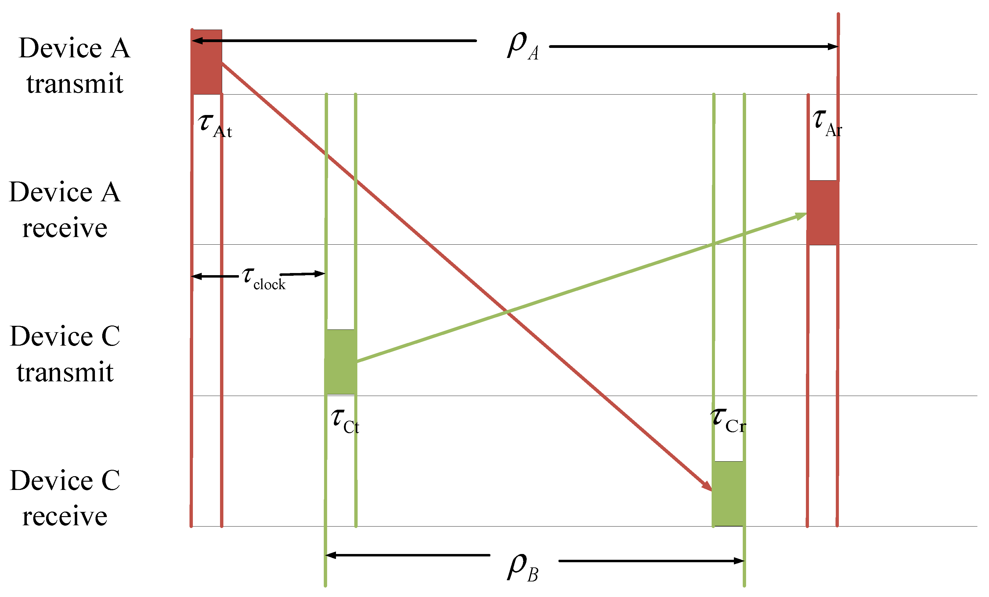
In the hardware system, the clock difference between multiple spacecraft will cause the ranging error. Therefore, we adopt dual one way ranging to measure the true ranging results, as well as to synchronize the clock of the whole network. The multiple devices exchange the local pseudo range measurement results. The true range D and clock difference Δ T clock between device C and device A are shown in Equation (19) and Figure 18.
{ D = 1 2 [ ( ρ A + ρ C ) ( τ Ar + τ At + τ Cr + τ Ct ) · c ] Δ t clock = 1 2 [ ( ρ A ρ C ) c + ( τ Ar τ At + τ Ct τ Cr ) ]
Here, ρ A and ρ C are the local ranging results with clock difference of devices A and C. τ At and τ Ct are the transmitting channel delay of device A and C. τ Ar and τ Cr are the receiving channel delay of devices A and C. c is the velocity of light. After the clock difference between slave devices and master device is obtained, devices A and B adjust the local clock to the master device.
Figure 18. The dual one way ranging.
Remotesensing 14 01653 g018

5. Discussion

The simulation and analysis above show the following:
(1)
The composite BOC signal can perform Doppler frequency measurement and high-speed communication at the same frequency. In addition, the communication signal and BOC signal are orthogonal in the time domain, which minimizes the influence of the BOC signal on the communication signal.
(2)
The paper gives the receiving algorithm of the composite signal. The algorithm includes the acquisition and tracking of the BOC signal and demodulation of the BPSK signal. By using the synchronization clock of the BOC signal for BPSK demodulation, the tolerance of the BPSK signal to a highly dynamic environment is increased, and the receiver design is simplified.
(3)
We discuss the fast-switching algorithm used to make the composite signal have better performance in spacecraft formation or UAVs. The reacquisition time after switching is reduced to one clock cycle.
(4)
We simulate and analyze the Doppler measurement and BER performance under different BOC and BPSK signal power ratios, as well as under different C/N0s. This shows that the BPSK signal will interfere with the BOC signal at low C/N0s. In this situation, the power ratio of the BOC signal needs to be improved. However, the performance of the BPSK signal is influenced only by its own power in the composite signal.
(5)
The fast-switching algorithm can operate at different C/N0s and signal power ratios in the case of the receiver regenerating local BOC signal to cancel the cross-correlation interference or the different nodes at similar distances.
(6)
The hardware platform can achieve all the functions of the composite BOC signal, which shows that the platform is feasible in the physical environment.

6. Conclusions

In this paper, we propose a BOC-derived signal with a data transmission function for a spacecraft formation or UAVs. The BOC signal inserts the BPSK signal at the central frequency of the traditional BOC signal. Moreover, the BPSK signal and BOC signal are orthogonal to each other in the frequency domain. The two function signals are received by the same baseband system at the same frequency point, which greatly simplifies the design and resource consumption of the receiving system. In addition, the BOC signal has better anti-interference performance and large dynamic tracking performance, which can better assist the demodulation of the BPSK signal.
The simulation and analysis show that, when the C/N0 at a high level, the two signals are not affected by each other. When the C/N0 is low, the performance of BOC signal will deteriorate, while the BPSK signal is still not affected. Furthermore, we designed the hardware of the BOC + BPSK signal in a multinode scenario, which can be used in the RF range of 200 MHz~6 GHz.

Author Contributions

Conceptualization, X.L. and W.W.; methodology, L.X.; software, J.D.; validation, L.X. and X.L.; formal analysis, L.X.; investigation, J.D.; resources, W.W.; data curation, L.X.; writing—original draft preparation, L.X.; writing—review and editing, L.X. and X.L. visualization, L.X.; supervision, L.X.; project administration, W.W. All authors have read and agreed to the published version of the manuscript.

Funding

This research was funded by the National Key R&D Program of China (No. 2021YFB3900300) and Technology and Industry for National Defense ( No. B0110).

Institutional Review Board Statement

Not applicable.

Informed Consent Statement

Not applicable.

Data Availability Statement

The study did not report any data.

Conflicts of Interest

The authors declare no conflict of interest.

References

  1. Li, C.; Chang, Q.; Zhao, N. A method of GMSK demodulation in inter-satellite link integration technology. In Proceedings of the 11th China Satellite Navigation Conference, Chengdu, China, 23–25 November 2020. [Google Scholar]
  2. Bai, Y.; Guo, Y.; Wang, X.; Lu, X. Satellite-Ground Two-Way Measuring Method and Performance Evaluation of BDS-3 Inter-Satellite Link System. IEEE Access 2020, 8, 157530–157540. [Google Scholar] [CrossRef]
  3. Yu, X.; Li, S.; Zhang, J.; Wang, Q.; Qiu, Y. Research on Unified Channel Method of Inter Satellite Radio TT&C and Data Transmission. In Proceedings of the 2021 International Conference on Microwave and Millimeter Wave Technology (ICMMT), Nanjing, China, 23–26 May 2021. [Google Scholar]
  4. Sessler, G.; Vassallo, E.; Visintin, M. Performance of GMSK for Telemetry and PN Ranging under Realistic Conditions. In Proceedings of the 6th ESA International Workshop on Tracking, Telemetry and Command Systems for Space Applications, Darmstadt, Germany, 10–13 September 2013. [Google Scholar]
  5. Sessler, G.; Vassallo, E.; Calzolari, G.P. GMSK/PN for High Rate Telemetry and High Accuracy Ranging of Lagrange and Mars Missions. In Proceedings of the 13th International Conference on Space Operations 2014, Pasadena, CA, USA, 5–9 May 2014. [Google Scholar]
  6. Zhao, N.; Chang, Q.; Wang, H.; Zhang, Z. An Unbalanced QPSK-Based Integrated Communication-Ranging System for Distributed Spacecraft Networking. Sensors 2020, 20, 5803. [Google Scholar] [CrossRef]
  7. Xia, X.Y.; Gao, F.; Han, X.D. An Improved Digital Carrier Synchronization Method for UQPSK. In Proceedings of the 5th International Conference on Information Science and Control Engineering (ICISCE), Zhengzhou, China, 20–22 July 2018; pp. 1076–1080. [Google Scholar]
  8. Ma, J.; Yang, Y. A generalized anti-interference low-ambiguity dual-frequency multiplexing modulation based on the frequency-hopping technique. IEEE Access 2020, 8, 95288–95300. [Google Scholar] [CrossRef]
  9. Xiong, H.; Wang, S.; Gong, S.; Peng, M.; Shi, J.; Tang, J. Improved synchronisation algorithm based on reconstructed correlation function for BOC modulation in satellite navigation and positioning system. IET Commun. 2018, 12, 743–750. [Google Scholar] [CrossRef]
  10. Juang, J.C.; Lin, C.T.; Tsai, Y.F. Comparison and Synergy of BPSK and BOC Modulations in GNSS Reflectometry. IEEE J. Sel. Top. Appl. Earth Obs. Remote Sens. 2020, 13, 1959–1971. [Google Scholar] [CrossRef]
  11. Ma, J.; Yang, Y.; Li, H.; Li, J. Expressions for the Autocorrelation Function and Power Spectral Density of BOC Modulation Based on Convolution Operation. Math. Probl. Eng. 2020, 2020, 2063563. [Google Scholar] [CrossRef]
  12. Lohan, E.S.; Lakhzouri, A.; Renfors, M. Binary-offset-carrier modulation techniques with applications in satellite navigation systems. Wirel. Commun. Mob. Comput. 2007, 7, 767–779. [Google Scholar] [CrossRef]
  13. Wang, C.; Cui, X.; Zhu, Y.; Lu, M. Thermal noise performance analysis for dual binary phase-shift keying tracking of standard BOC signals. IET Radar Sonar Navig. 2020, 14, 1019–1028. [Google Scholar] [CrossRef]
  14. Li, M.; Qu, L.; Zhao, Q.; Guo, J.; Su, X.; Li, X. Precise Point Positioning with the BeiDou Navigation Satellite System. Sensors 2014, 14, 927–943. [Google Scholar] [CrossRef] [Green Version]
  15. Sun, X.; Zhou, Q.; Ji, Y.; Fu, Q.; Miao, Q.; Wu, S. An Unambiguous Acquisition Algorithm for BOC (n, n) Signal Based on Sub-correlation Combination. Wirel. Pers. Commun. 2019, 106, 1609–1628. [Google Scholar] [CrossRef]
  16. Wang, B.; Li, T.; Wei, J.; Tang, Z. A new unambiguous tracking algorithm for sine-BOC(m, n) signals. GPS Solut. 2019, 23, 58. [Google Scholar] [CrossRef]
  17. Ma, J.; Yang, Y.; Li, H.; Li, J. FH-BOC: Generalized low-ambiguity anti-interference spread spectrum modulation based on frequency-hopping binary offset carrier. GPS Solut. 2020, 24, 70. [Google Scholar] [CrossRef]
  18. Julien, O.; Macabiau, C.; Cannon, M.E.; Lachapelle, G. ASPeCT: Unambiguous sine-BOC (n, n) acquisition/tracking technique for navigation applications. IEEE Trans. Aerosp. Electron. Syst. 2007, 43, 150–162. [Google Scholar] [CrossRef] [Green Version]
  19. Benedetto, F.; Giunta, G.; Lohan, E.S.; Renfors, M. A Fast Unambiguous Acquisition Algorithm for BOC-Modulated Signals. IEEE Trans. Veh. Technol. 2013, 62, 1350–1355. [Google Scholar] [CrossRef]
  20. Tang, Z.; Zhou, H.; Wei, J.; Yan, T.; Liu, Y.; Ran, Y.; Zhou, Y. TD-AltBOC: A new COMPASS B2 modulation. Sci. China-Phys. Mech. Astron. 2011, 54, 1014–1021. [Google Scholar] [CrossRef]
  21. Lee, Y.; Chong, D.; Song, I.; Kim, S.Y.; Jee, G.I.; Yoon, S. Cancellation of Correlation Side-Peaks for Unambiguous BOC Signal Tracking. IEEE Commun. Lett. 2012, 16, 569–572. [Google Scholar] [CrossRef]
  22. Feng, T. Decimation Double-Phase Estimator: An Efficient and Unambiguous High-Order Binary Offset Carrier Tracking Algorithm. IEEE Signal Processing Lett. 2016, 23, 905–909. [Google Scholar] [CrossRef]
  23. Zhang, Y.; Lu, W.; Chen, H.; Yu, D. Insight to Double Estimator Technique: The concept of subcarrier aided code tracking. In Proceedings of the 2015 International Conference on Communications and Signal Processing (ICCSP), Melmaruvathur, India, 3–5 April 2015. [Google Scholar]
  24. Mishra, D.; Kumar, M. Design and Implementation of a Novel Digital Interplex Modulator for Future Navigation Satellite System. In Proceedings of the 2014 International Conference on Signal Processing and Integrated Networks (SPIN), Noida, Delhi, India, 20–21 February 2014. [Google Scholar]
  25. Dafesh, P.A.; Khadge, G.K. Phase Optimized Constant Envelope Transmission (POCET) and the Method of Phantom Signals. In Proceedings of the ION 2017 Pacific PNT Meeting, Honolulu, HI, USA, 1–4 May 2017; pp. 100–117. [Google Scholar]
  26. He, T.; Ma, Z. Proposed OFDM modulation for future generations of GNSS signal system. J. Navig. 2016, 69, 971–990. [Google Scholar] [CrossRef] [Green Version]
  27. Saxena, T.; Jadon, J.S. Spectral analysis of Sine and Cosine BOC modulated signals. In Proceedings of the 2014 International Conference on Signal Processing and Composite Networks (SPIN), Noida, India, 20–21 February 2014; pp. 734–738. [Google Scholar]
  28. Zitouni, S.; Rouabah, K.; Chikouche, D.; Mokrani, K.; Atia, S.; Harba, R.; Ravier, P. General analytical models characterizing MBOC modulated signal. Aerosp. Sci. Technol. 2016, 50, 112–126. [Google Scholar] [CrossRef]
  29. Nie, S.J.; He, B.Z.; Wang, H.Z.; Qin, Y.F. Design of integration channel of ranging and data transmission. Mod. Electron. Tech. 2013, 36, 57–62. [Google Scholar]
  30. Kinman, P.W. Doppler tracking of planetary spacecraft. IEEE Trans. Microw. Theory Tech. 1992, 40, 1199–1204. [Google Scholar] [CrossRef]
  31. Lin, K.; Zhan, X.; Yang, R.; Shao, F.; Huang, J. BDS Space Service Volume characterizations considering side-lobe signals and 3D antenna pattern. Aerosp. Sci. Technol. 2020, 106, 106071. [Google Scholar] [CrossRef]
  32. Yoon, S.; Chae, K.; Kim, S.Y. A New Approach to Local Signal Design for Enhanced TMBOC Signal Tracking. J. Electr. Eng. Technol. 2020, 15, 1837–1845. [Google Scholar] [CrossRef]
  33. Lu, B.; Zhong, J.; Zhao, M.; Li, L. A near-far effect canceller for GPS high sensitivity receiver. In Proceedings of the 2012 IEEE/ION Position, Location and Navigation Symposium, Myrtle Beach, SC, USA, 23–26 April 2012. [Google Scholar]
  34. Yang, W.; Meng, S.; Wang, J.; Liu, J. Acquisition performance analysis of a synchronizati. In Proceedings of the 2009 9th International Conference on Electronic Measurement & Instrumentson scheme of DS/FH hybrid spread spectrum signals for TT&C, Beijing, China, 16–19 August 2009; pp. 4-395–4-399. [Google Scholar]
  35. Crisan, A.M.; Martian, A.; Cacoveanu, R.; Coltuc, D. Evaluation of synchronization techniques for inter-satellite links. In Proceedings of the 2016 International Conference on Communications (COMM), Bucharest, Romania, 9–10 June 2016; pp. 463–468. [Google Scholar]
  36. Meng, S.; Yang, W.; Lu, W.; Liu, J.; Yu, J. Code tracking performance of DS/FH spread spectrum signal for TT&C. In Proceedings of the 2010 2nd IEEE International Conference on Information Management and Engineering, Chengdu, China, 16–18 April 2010; pp. 491–495. [Google Scholar]
  37. Li, T.; Tang, Z.; Wei, J.; Zhou, Z.; Wang, B. Unambiguous Tracking Technique Based on Combined Correlation Functions for Sine BOC Signals. J. Navig. 2019, 72, 140–154. [Google Scholar] [CrossRef]
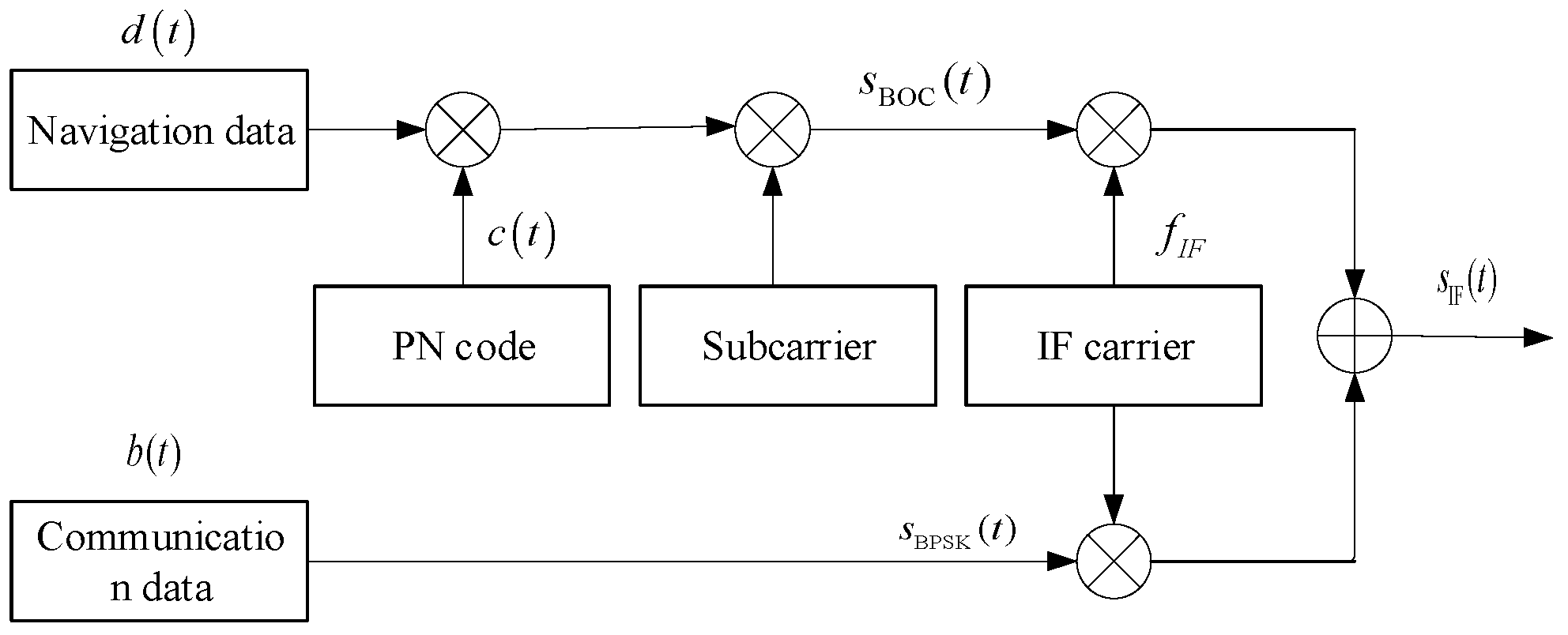
Figure 1. The transmitter of the composite signal.
Remotesensing 14 01653 g001
Figure 2. Characteristics of the BOCcos(5,5) and BPSK(5) composite signals. (a) α : β = 0.3 : 0.7 ; (b) The power spectrum of different α and β ratios.
Remotesensing 14 01653 g002
Figure 3. The reception of composite signal.
Remotesensing 14 01653 g003
Figure 4. The structure of the tracking loop.
Remotesensing 14 01653 g004
Figure 6. The application scenario.
Remotesensing 14 01653 g006
Figure 8. The acquisition process.
Remotesensing 14 01653 g008
Figure 9. Single acquisition success probability under different situations.
Remotesensing 14 01653 g009
Figure 10. Performance of the composite signal and pure signal: (a) Doppler frequency measurement results of the composite signal and pure BOC signal, and (b) ranging results of the composite signal and pure BOC signal.
Remotesensing 14 01653 g010
Figure 11. The data transmission error rate of a composite signal and pure signal.
Remotesensing 14 01653 g011
Figure 12. The switching time when α : β = 0.5 : 0.5 and C/N0 = 65 dB-Hz. (a) the Doppler frequency error, and (b) the Doppler frequency measurement.
Remotesensing 14 01653 g012
Figure 13. The switching time when α : β = 0.3 : 0.7 and C/N0 = 65 dB-Hz. (a) the Doppler frequency error, and (b) the Doppler frequency measurement.
Remotesensing 14 01653 g013aRemotesensing 14 01653 g013b
Figure 14. The switching time when α : β = 0.1 : 0.9 and C/N0 = 65 dB-Hz. (a) the Doppler frequency error, and (b) the Doppler frequency measurement.
Remotesensing 14 01653 g014
Figure 15. The switching time when α : β = 0.1 : 0.9 and C/N0 = 55 dB-Hz. (a) the Doppler frequency error, and (b) the Doppler frequency measurement.
Remotesensing 14 01653 g015
Figure 16. The switching time when α : β = 0.1 : 0.9 and C/N0 = 45 dB-Hz. (a) the Doppler frequency error, and (b) the Doppler frequency measurement.
Remotesensing 14 01653 g016aRemotesensing 14 01653 g016b
Figure 17. The hardware test environment. (a) The test environment, and (b) the hardware picture.
Remotesensing 14 01653 g017
Table 1. The parameter of simulation scenario.
ParameterValue
Distance between different nodesWithin 100 km
Relative movement speed1020 m/s
Radio frequency of VHF bandUplink 200 MHz/
Downlink 300 MHz
Radio frequency of S bandUplink 2.9 GHz/
Downlink 3.1 GHz
Maximum Doppler frequency of VHF bandUplink 2550 Hz/
Downlink 3825 Hz
Maximum Doppler frequency of S bandUplink 9860 Hz/
Downlink 10,540 Hz
Equivalent isotropically radiated power (EIRP) of VHF band45 dBm
Equivalent isotropically radiated power (EIRP) of S band47 dBm
VHF band receiving antenna gain8 dBi
S band receiving antenna gain28 dBi
Table 2. The hardware test results.
ParameterValue
Acquisition time0.034489 s
Acquisition frequency8950 Hz
Radio frequency of S bandUplink 2.9 GHz/
Downlink 3.1 GHz
The SNR of communication signal at receiving end11 dB
The C/N0 of navigation and measurement signal at receiving end65 dB-Hz
The Doppler frequencySinusoidal variation with amplitude 12 kHz, period 3 s
Channel attenuationRice fading channel
Doppler measurement accuracy<0.01 m/s
Ranging accuracy<0.1 m
BER8.964 × 10−7
Publisher’s Note: MDPI stays neutral with regard to jurisdictional claims in published maps and institutional affiliations.