Abstract
When a target is moving at high-speed, its high-resolution range profile (HRRP) will be stretched by the high-order phase error caused by the high velocity. In this case, the inverse synthetic aperture radar (ISAR) image would be seriously blurred. To obtain a well-focused ISAR image, the phase error induced by target velocity should be compensated. This article exploits the variation continuity of a high-speed moving target’s velocity and proposes a noise-robust high-speed motion compensation algorithm for ISAR imaging. The target’s velocity within a coherent processing interval (CPI) is modeled as a high-order polynomial based on which a parametric high-speed motion compensation signal model is developed. The entropy of the ISAR image after high-speed motion compensation is treated as an evaluation metric, and a parametric minimum entropy optimization model is established to estimate the velocity and compensate it simultaneously. A gradient-based solver of this optimization is then adopted to iteratively find the optimal solution. Finally, the high-order phase error caused by the target’s high-speed motion can be iteratively compensated, and a well-focused ISAR image can be obtained. Extensive simulation experiments have verified the noise robustness and effectiveness of the proposed algorithm.
1. Introduction
Inverse synthetic aperture radar (ISAR) imaging plays an important role in space target surveillance due to its long-range, all-day, all-weather, and two-dimensional high-resolution imaging capability [1,2]. In general, the slant high-range resolution depends on transmitting wide-band linear frequency modulation (LFM) waveforms with a large pulse width. In contrast, the high azimuth resolution depends on the relative motion between the radar and the observed targets over the coherent processing interval (CPI) [3,4]. When the target is stationary or its velocity is low, the “stop–go” model is used to analyze the target echo signals [5,6]. After de-chirp processing on the receiver [7,8], the range profile of the signal can be directly extracted from the pulse compression by the Fast Fourier transform (FFT). However, for a target moving at high speed (such as missiles and satellites), their high-resolution range profile (HRRP) would be stretched by the high-order phase error induced by target velocity [9,10,11]. Velocity estimation and compensation are of particular significance for the ISAR imaging of high-speed moving targets, which deteriorates the quality of HRRP and ISAR image [12,13]. Therefore, to not affect the subsequent ISAR imaging processing, it is necessary to estimate the target speed and compensate for the phase error caused by the high-speed motion.
The key to the high-speed motion compensation of ISAR imaging lies in accurately estimating the target’s high velocity. The current methods are divided into two main categories. One category is the algorithms based on signal decomposition to estimate the high-order phase error parameters directly for individual echo and then directly acquire the velocity for high-speed motion compensation. The fractional Fourier transform (FrFT) [14,15] and its modification [16] have been utilized to reconstruct HRRP for high-speed moving targets. Furthermore, many parameter estimation methods, such as the integrated cubic phase function (ICPF) [17,18], particle swarm optimization [19], Wigner Ville Distribution (WVD) and Hough Transform (HT) [20], etc., were utilized to estimate the target velocity from the quadratic phase error. These methods model the radar echo after pulse compression as the sum of multiple signals containing quadratic phase error, then compensate the high-speed motion by estimating the signal chirp term that contains the target velocity. This category of method relies on an accurate estimation of the signal’s chirp term, which is susceptible to noise. Another class of methods uses the focusing quality of the HRRP as a criterion for the indirect estimation of velocity, and the most typical criterion is the waveform entropy [11,21,22]. Entropy is an effective metric for evaluating the focusing quality of HRRP and is used in many ISAR imaging applications such as translational motion compensation [23,24,25] and image auto-focusing processing [26,27,28,29]. This class of methods creates a higher-order compensation term for each compressed echo and establishes a parametric model for individual echo high-speed motion compensation. Then, the phase error is searched and compensated by minimizing the waveform entropy. The problem with these algorithms is that they treat each pulse independently, ignoring the continuity and the integrity of a high-speed moving target’s motions during continuous observation. Due to the separate processing of the echoes, each echo’s high-speed motion estimation error gradually accumulates within a CPI, resulting in an inefficient high-speed compensation of the image as a whole. In addition, the signal-to-noise ratio (SNR) of the echo is often relatively low for targets due to the signal decay from the long range and absorption of the transmitting medium. The SNR problem is among the most significant challenges that ISAR imaging systems frequently face. In the presence of low SNR, the high-speed motion compensation always encounters some difficulties [17,30,31]. As a result, the imaging results would degrade seriously.
Aiming to perform the ISAR imaging of a high-speed moving target, this paper proposes a noise-robust high-speed motion compensation method for ISAR imaging based on parametric minimum entropy optimization. Firstly, for the radar echoes of high-speed moving targets in the De-chirp mode [7], we analyze the influence of the high-speed motion of the target on the compressed echoes and establish the signal model for the high-speed moving target. In general, for a continuously observed target, its movement state, including its trajectory and velocity, changes in a continuous manner [25,32,33,34]. Considering the variation continuity of the target’s velocity within one CPI, the target’s velocity is modeled as a high-order polynomial function, and 2D image entropy is minimized to optimize the velocity polynomial coefficients. A novel coordinate descent algorithm is proposed to solve the minimum entropy optimization based on the established minimum entropy optimization model. The coordinate descent algorithm is implemented by the Broyden–Fletcher–Goldfarb–Shanno (BFGS)-based quasi-Newton algorithm [35,36,37] yields fast convergence. The effectiveness of the high-speed compensation algorithm is verified by simulation data and Yak-42-measured data. Compared with existing algorithms, the proposed method is innovative in the following aspects:
(1) The most significant advantage of the proposed method is that it considers the correlation of velocity variations of sequential echoes during one CPI. The continuity and completeness of the target velocity variation are exploited to establish the high order polynomial of the sequential echo’s velocity for the high-speed motion compensation. Compared with the high-speed motion compensation method based on independent echo, the proposed method is more robust and has higher compensation accuracy.
(2) Most of the existing high-speed compensation methods use exhaustive search or signal parameter estimation, which is computationally expensive and sensitive to noise. In contrast, the proposed method uses the 2D ISAR image’s entropy as an evaluation index. This uses the BFGS algorithm, which is an effective quasi-Newton algorithm that does not need to calculate the second-order derivative of the objective function. The operational speed of the BFGS algorithm is faster than that of the Newton method. That is to say, the proposed algorithm is more effective and practical.
(3) The existing high-speed motion compensation methods do not take full advantage of the high accumulation gain of sequential echoes. The proposed method can achieve high SNR gain from 2D coherent integration [33,34], which benefits the high-speed motion compensation under low SNR.
This paper is organized as follows. Section 2 presents the De-chirped signal model for high-speed moving targets. In Section 3, a parametric model of the high-speed motion compensation within one CPI is established. The minimum entropy optimization is developed, and the gradient-based solver of this optimization problem is introduced. In Section 4, some imaging results based on the simulated and measured data are given, and the performance of the proposed high-speed compensation method is analyzed. Some conclusions are given in Section 5.
2. De-Chirp Signal Model for High-Speed Moving Targets
A general geometry of the radar and target is given in Figure 1, in which a coordinate is built on the center gravity O of the target with the Y axis along the direction of LOS. In Figure 1, the plane consisting of the XY axis including the line of radar sight (LOS) is the imaging plane. The final ISAR image is the projection of the 3D target structure on the imaging plane. In radar imaging, the high range resolution is usually achieved by transmitting large band-width linear-frequency-modulated (LFM) signals with pulse compression. Assuming the radar transmits a chirp waveform that
where , and , , and denote the pulse-width, carrier frequency, and frequency modulation rate, respectively. is the full time, where is the fast time and is the slow time. As shown in Figure 1, the point p is an arbitrary scatterer on the target whose distance from the radar at is ; then the radar echo of this scatter can be written as
where is the echo time delay of point p, c is the velocity of light, is the reflection coefficient. Note the instantaneous distance from the radar to scatter p, i.e., is only related to slow time because a “stop–go” assumption is adopted, i.e., the radar target is supposed to move between radar pulses and stop within each pulse, as shown in Figure 2a. Noting the pulse width of the wide-band signal is generally narrow, e.g., 100 us, the “stop–go” assumption is reasonable and has been widely used in ISAR imaging. For the target moving with high velocity, however, the target movement within a pulse cannot be ignored and the assumption of “stop-go” is invalid. For example, assuming that the radar transmits an LFM signal with a bandwidth of 1 GHz and a pulse width of 100 us, for a slow-moving target with a speed of 100 m/s (such as an airplane), the distance variation within a pulse is 0.01 m. Furthermore, for a high-speed moving target with a speed of 3000 m/s (such as the satellite), the distance variation within a pulse is 0.3 m. Compared to the range resolution m, the distance variation within the pulse for the slow-moving target can be ignored, while it can not be neglected for the high-speed moving target. For high-speed moving targets, since it is necessary to consider the target distance variation within one pulse-width, the distance between point p and the radar is the variable concerned with both fast time and slow time , which can be expressed as
where is the distance variation with slow time, and is the distance variation with the fast time. Considering the fact that a pulse time is short and the change of velocity within a pulse time can be neglected, i.e., the target can be approximated to be moving at a uniform speed within a pulse, then can be approximated as
where is the instantaneous velocity of the target at slow time . The de-chirp compression processing is expressed as the echo signal multiples with the reference signal’s conjugate [7]. The reference signal is
where , is the reference distance from point p to the radar at slow time . After the de-chirp processing, we can obtain the output signal
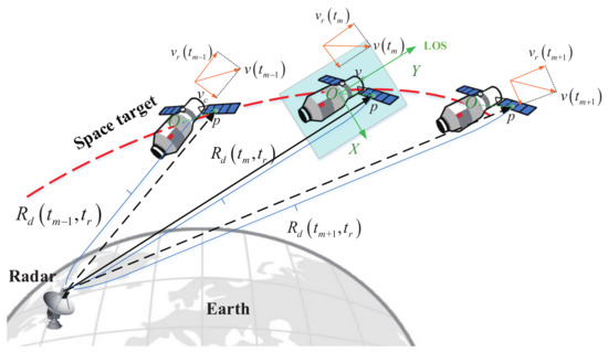
Figure 1.
Observation geometry for high-speed motion targets.
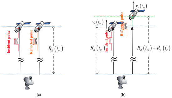
Figure 2.
Difference between low-speed moving target and high-speed moving target: (a) the low-speed moving target; and (b) the high-speed moving target.
Simplifying Equation (6) yields
where
where is the chirp term caused by the high-speed motion of the target. In ISAR imaging, the target’s motion can be divided into translational and rotational motion [6], respectively, as shown in Figure 3. Assuming that the coordinate of the point p in the imaging plane is , the instantaneous distance from scattering point p to radar is given by
where denotes the translational motion of the target, as shown in Figure 3. In ISAR imaging, since the time of a CPI is very short, such as a few milliseconds, the rotation of the target relative to the radar within a CPI is a few degrees (approximately ), and the target can approximate uniform rotation in a short time. At this time, the terms and in Equation (9) satisfy , where is the rotational velocity of the target in the imaging plane. Bringing Equation (9) into Equation (7) yields
where is the wavelength, and the phase in Equation (10) is divided into eight terms. The first term is the rotational Doppler term of point p and the second term is the range compression term of point p. These two terms are the time domain data corresponding to the final image of the target. The third term is constant and can be ignored. The fourth term is the range walk term due to rotational motion, which usually does not exceed one range cell in ISAR imaging, whose effect can be neglected [38,39]. The fifth term is the phase error from the translational movement of the target as a whole, which can be removed by the autofocus algorithm [6,40,41]. The 6th term is the residual video phase (RVP) error, which can be removed by RVP compensation. The seventh term is the envelope linear walk term brought by the target translational and high-speed motion, which can be eliminated by envelope alignment [23,42]. The eighth term is the range chirp term brought by the high-speed movement of the target, which needs to be compensated in this paper. After the envelope alignment [23] and phase error compensation [40], Equation (10) becomes
where is the time domain data of the ideal image after high-speed compensation, denoted as
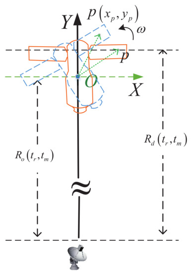
Figure 3.
Target’s rotational motion in ISAR imaging.
According to Equation (11), the high-speed compensation signal model for ISAR imaging can be expressed as
Applying the fast Fourier transform (FFT) with respect to and and considering the inevitable noise, Equation (13) can be expressed in a discrete form as
where is the ISAR image after high-speed motion compensation. , k is the range indices, N is the number of range bins, and , where h is the azimuth position and M is the number of azimuth cells. is the discrete form of , n and m are the discrete form of and , denotes the complex noise. Equation (14) is the signal model of the final ISAR images after high-speed motion compensation. In the following sections, the parametric minimum entropy optimized high-speed motion compensation algorithm is given based on this signal model.
3. Optimal Compensation for High-Speed Motion
3.1. Optimization Based on Parametric Minimum Entropy
From Equation (14), it can be seen that the velocity of the target varies with the slow time . The high-speed compensation for independent echoes does not consider the continuity of velocity variation [15,20,21]. Due to the complex motion of the target and the variance of the system and the environment, the high-velocity between the target and the radar usually has high-order terms [24,25,33,34]. Without loss of generality, we model the target’s high-velocity as an L-order polynomial, meaning that
where l denotes the order of velocity variation with slow time , , and represents the coefficient of each order. denotes the pulse repetition time (PRT). One notes that l begins from 0 to , indicates the initial value of the velocity. For simplicity and clarity, we define the polynomial coefficient vector as , and give the complex image after error correction by the high-speed compensation term as follows:
If the values of are obtained precisely, the high-speed motion of the target will be compensated, and a well-focused ISAR image can be obtained. Therefore, the high-speed motion compensation problem turns into an optimal parameter estimation problem. Actually, estimating the optimal parameters set in can be transferred into solving an unconstrained optimization problem in which are the variables of objective function.
Image entropy [25,26,27] and contrast [37,41] are frequently used in ISAR imaging to quantify the image focus. In this paper, image entropy is employed to evaluate the focus quality of images. Entropy has been used as a typical indicator in ISAR imaging in many different ways [28,29]. The entropy of the 2-D image represents its sharpness, and generally, the “sharpest” image corresponds to the entirely focused image. The complex image after high-speed motion correction by can be rewritten as
Therefore, the entropy of an image is defined as a function of , which is given by
where is the image intensity that can be expressed as
The estimate of is obtained by minimizing the image entropy, expressed as follows:
To date, the optimization based on entropy minimization for high-speed motion compensation is established, and it is an optimization function with series parameters . Many standard algorithms are available to solve this optimization, such as particle swarm optimization (PSO) and genetic algorithms (GA) [19]. However, these nonparameteric methods always need great computation time. BFGS is an effective quasi-Newton algorithm that efficiently solves unconstrained optimization problems. In the following subsection, we present a fast iterative optimization search method based on the BFGS quasi-Newton iteration method [37].
3.2. Parameter Optimization Based on Fast Iteration
To apply the BFGS-based fast iterative search method, one first has to obtain the gradient of each parameter. For an arbitrary parameter , , its gradient is
where ; then, we have
where
With the partial derivative expressions in Equation (23), the gradient of image entropy with respect to is
In the BFGS algorithm, an approximate matrix (defined as , whose initial form is ), is used to replace the Hessian matrix of the objective function. In this paper, since we are searching for each polynomial parameter individually, . In addition, considering the considerable number of velocity polynomial parameters, it is difficult to ensure the algorithm’s convergence speed and convergence robustness if the joint iterative search is performed for all parameters simultaneously. Therefore, to improve the convergence speed while providing the algorithm’s robustness, a BFGS-based quasi-Newton coordinate descent algorithm was used in this paper. Herein, this paper minimized the entropy with respect to a single parameter while holding the other parameter constant to avoid the local optimum. For example, for the parameter , with the first parameters ∼ which are already iteratively updated, the minimum entropy optimization function of can be expressed as
In the coordinate descent iterative algorithm, each parameter is solved independently iteratively and optimally. Considering that in Equation (25), , . Taking this into Equation (23), the gradient of the independent parameter can be expressed as
For each parameter , its iterative solution process is based on the BFGS algorithm. Let be the initial parameter and be the parameter of the iteration. The searching direction in BFGS is updated as follows:
The parameter is updated as follows:
where is the search step corresponding to at the iteration. It can be estimated by Equation (29) via some 1-D inexact searching methods, such as golden section search or the Armijo–Goldstein stepsize rule [37].
The Hessian matrix in BFGS is updated as follows:
where , .
All parameters are updated throughout the parameter optimization process in two loop iterations, the inner and outer loops, respectively. Within the inner loop, for the parameter , , the parameters are independently updated based on BFGS from ∼ in turn, and each parameter is independently updated as an inner loop. When all parameters are updated once, it is an outer loop, and after completing an outer loop, it goes to a new outer loop. Until the image entropy satisfies a certain value, the iteration stops.
To clearly describe the proposed algorithm, a flowchart of the proposed algorithm is given in Figure 4.
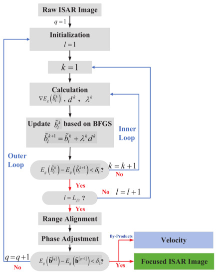
Figure 4.
The flow chart of the proposed algorithm.
As can be seen from the flow chart, first, the polynomial order is selected. Since the time of a CPI is very short, say less than 1 s, the target’s velocity variation is small, and a velocity polynomial of order 1–2 can accurately describe the high-speed motion of the target. In this paper, L is set to 5 to make the proposed algorithm more robust, i.e., it can satisfy the case of weak target maneuver as well as the case of strong target maneuver. For , the algorithm only sacrifices a small amount of computation time, but this will make the high-speed compensation more accurate and robust. The iterative process is divided into an inner loop and an outer loop. The inner loop is a BFGS-based gradient search for each polynomial parameter independently. After a complete search estimation of all order coefficients, the range alignment and phase adjustment were re-implemented. This process is an outer loop, where and are the inner loop and outer loop iteration termination conditions, respectively. In general, , are usually a good choice in reality. It is important to emphasize that after all the coefficients are updated, the range profile of each pulse will be changed because the high-speed motion of the target was compensated to a certain extent. Hence, it is necessary to realign all the echo envelopes [23] and refocus the image [26,27] for the next iteration.
4. Experiment Analysis
To verify the effectiveness of the proposed algorithm, in this subsection, different experiments were designed to demonstrate the performance of the proposed algorithm. The experiments are divided into the three types and all the images are generated by the conventional range-Doppler (RD) [1] imaging algorithm. The difference is that different high-speed motion compensation algorithms are used. For all experiments, the proposed method is compared with the algorithm in [21], which uses the idea of minimum entropy of individual echoes for high-speed compensation. It is referred to as ME. The proposed algorithm is also compared with the algorithm proposed in [17], which uses ICPF to estimate the chirp coefficients of independent echoes and thus for high-speed compensation. It is referred to as ICPF in this paper. It is important to emphasize that before the high-speed motion compensation, the translation compensation [23] and the phase error compensation [40] are applied to compensate for the fifth, sixth, and seventh terms in Equation (10).
(1) Firstly, point simulation experiments are designed to verify the performance of the proposed algorithm under different high-speed motion conditions.
(2) Considering the difficulty of obtaining the real measurement data of the space target, this paper uses the electromagnetic simulation data of the space target for the experiment, and the PO algorithm [43] obtains simulation data. In addition, to illustrate the robustness of the proposed algorithm in the case of low SNR, the performance of the proposed algorithm under different SNR conditions is given in the experiments.
(3) In this part of the experiment, different high-speed motion was added to the Yak-42 real measured data to evaluate the effectiveness of the proposed method, and the high-speed motion was added using Equation (11).
4.1. Experiments Based on Point Array Simulation
The first experiment is based on scattering point simulation. A simulated ballistic missile consisting of 13 scatterers is constructed as shown in Figure 5b, which is supposed to fly straight above the radar with different projected velocities. The motion model is given in Figure 5a. The radar transmits a linear frequency modulation (LFM) signal with the parameters given in Table 1. The signal-to-noise ratio (SNR) of the radar echo is 20 dB. The radar echo simulation was carried out under different high-speed motion conditions, as shown in Table 2. In this paper, the SNR of a signal is defined as
where denotes the energy of the radar echo, and denotes the energy of white Gaussian noise.

Figure 5.
(a) Target movement trajectory; (b) the scattering point model; and (c) the ideal image of zero velocity.

Table 1.
Radar parameters of the simulation.

Table 2.
Motion parameters for the simulation.
The high-speed compensated ISAR imaging results under different motion conditions are shown in Figure 6, all the imaging results were obtained using the RD imaging algorithm [1]. The left column of Figure 6 is the ISAR images without high-speed motion compensation. It can be seen that, as the target speed increases, the high-speed motion also has an increasing impact on the ISAR imaging results, and the images become increasingly blurred. The second column of Figure 6 shows the ISAR images acquired by the ME. It can be seen that the focusing image quality is significantly improved by using the high-speed compensation algorithm. The third column of Figure 6 shows the ISAR images acquired by the ICPF. It can be seen that the image focusing quality obtained by ICPF is basically the same as that of the ME algorithm. Compared with uncompensated images, the scattered points in the images are well focused. The fourth column of Figure 6 shows the focused ISAR images acquired by the proposed algorithm, and it can be seen that the proposed algorithm achieves images with better focusing quality. For comparison, the entropy of the images after high-speed compensation by different algorithms are given, as shown in Table 3. As can be seen from the table, compared with the ME and ICPF, the image entropy obtained by the proposed algorithm is smaller and closer to the ideal image. The variation of the image entropy with the iteration number of the proposed algorithm is given in the right column of Figure 6, and it can be seen that the proposed algorithm reaches convergence after approximately ten iterations. Considering that the first and second-order of the target velocity dominate the influence within a CPI, the image entropy against the velocity and acceleration are given in Figure 7a–d. It can be seen that the adoption of the global image entropy as the evaluation criterion has a global minimum, and the algorithm can robustly converge to the global optimum.
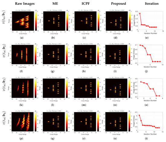
Figure 6.
High-speed compensated imaging results under different motion conditions. The leftmost column is the imaging results without high-speed motion compensation; the second column is the high-speed compensation imaging results by ME; the third column is the high-speed compensation imaging results by ICPF; the fourth column is the high-speed compensation imaging results of the proposed algorithm; the rightmost column is the image entropy against the iteration number of the proposed algorithm.

Table 3.
The entropy of images acquired by different algorithms.
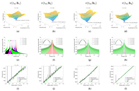
Figure 7.
(a–d) Image entropy variation with velocity and acceleration; (e–h) range profiles of individual scattering points in ISAR images; and (i–l) velocity estimation and its true value of different high-speed compensation algorithms at different motion conditions.
To better reflect the advantages of the proposed algorithm, the range profiles of the independent scattering points of the image are given in Figure 7e–h. From Figure 7e, it can be seen that as the target velocity continues to increase, the range chirp term brought by the high-velocity becomes more and more prominent, and the profile spreading after range compression becomes more and more serious. The range profile after high-speed motion compensation is shown in Figure 7f–h, and it can be seen that after high-speed motion compensation, the main lobe broadening of the independent points disappears, forming a well-focused range compression lobe. However, compared with the proposed algorithm, the main lobe of the range profile after the compensation of ME and ICPF still has the spreading phenomenon. In contrast, after the compensation of the proposed algorithm, the main lobe has no broadening.
Figure 7i–l gives the estimated velocity of the three algorithms and the true velocity. One can see that since the ME and ICPF algorithms process each echo independently from the velocity estimation, the estimated velocity is not correlated. The velocity estimates of each pulse are independent of each other. There are many speed estimates that deviate significantly from the true value, which will eventually lead to inadequate image compensation. In contrast, the proposed algorithm considers the continuity of the target’s velocity variation within a CPI, and the estimated velocity is consistent with the actual value which also reflects the effectiveness of the proposed algorithm. The root mean square error (RMES) of velocity estimated by different algorithms is shown in Table 4, and RMES is defined as
where is the estimated velocity and is the true velocity. It can be seen from the RMSE that the estimation error of the proposed algorithm is much lower than the errors of the comparison methods, which proves the effectiveness of the proposed algorithm.

Table 4.
Estimated speed RMSE of different algorithms with point simulation experiments.
4.2. Experiments Based on TG-I’s Electromagnetic Simulation
Since satellite data are rarely publicly available, the experimental data in this subsection are obtained based on electromagnetic simulations with the electromagnetic model TG-1, whose 3D model is shown in Figure 8a. All simulations adopt a triangular facet model to divide the target surface into thousands of equivalent scatterers. The radar echo data of a solid object are calculated by adopting the fast physical optics (FPO) algorithm [1], and the conventional RD algorithm generates the ISAR images for EM simulation. To illustrate the validity of the EM simulation, a comparison between the real ISAR image of TG-I (Figure 8a) and the EM simulation ISAR image (Figure 8b) is given in Figure 8. The German FGAN Lab published the measurement image of TG-I in March 2018 (at Fraunhofer FHR, available at https://www.fhr.fraunhofer.de/tiangong-bilder; accessed on 21 March 2018). The comparison result shows that the performance of the generated imagery is close to that of the measured ISAR image, which supports the investigation in this article. The radar parameters and target’s motion parameters used for the simulation are the same as the experiments in the previous section.

Figure 8.
(a) The CAD model of TG-I satellite; (b) real ISAR image; and (c) EM simulation ISAR image.
First, the imaging results of the different algorithms for high-speed compensation under different motion conditions are given, as shown in Figure 9. The left column of Figure 9 shows the imaging results without high-speed motion compensation, where one can see that as the target speed increases, the blurring of the ISAR images becomes increasingly severe, and the entropy value of the images becomes larger. When looking at the two high-speed compensation algorithms, since the electromagnetic simulation is closer to the actual measurement data than the previous simple scattering point simulation, the high-speed compensation of ME and ICPF is not satisfactory. The focusing quality of the images is minimally improved. In contrast, the algorithm proposed in this paper can still accurately compensate, and the image after high-speed compensation can be accurately focused, reflecting the robustness of the proposed algorithm. For comparison, the entropy of the images after high-speed compensation by different algorithms are given, as shown in Table 5. As can be seen from the table, compared with the ME and ICPF, the image entropy obtained by the proposed algorithm is smaller and closer to the ideal image. From Figure 10, it can be seen that the estimated velocity using ME and ICPF have a significant error, and the bias between the estimated velocity and the true value can reach several kilometers per second, which is the main reason for the failure of the algorithm. In contrast, the estimated velocity of the proposed algorithm basically matches the true value, and the error is basically negligible, which reflects the effectiveness of the proposed algorithm. Similarly, the RMSE for the speed estimation of different algorithms is given, as shown in Table 6. From the table, it can be seen that the speed estimation of the proposed algorithm is more accurate and has less error.
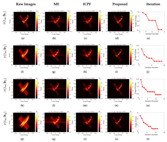
Figure 9.
Experimental results of TG-I electromagnetic simulation under different motion conditions. The leftmost column shows the imaging results without high-speed motion compensation; the second column shows the high-speed compensation imaging results by ME; the third column shows the high-speed compensation imaging results by ICPF; the fourth column shows the high-speed compensation imaging results of the proposed algorithm; the rightmost column is the image entropy against the iteration number of the proposed algorithm.

Table 5.
The entropy of images acquired by different algorithms using TG-I EM simulation data.

Figure 10.
Comparison of the estimated velocity and real velocity using TG-I EM simulation data under different motion conditions.

Table 6.
Estimated speed RMSE of different algorithms using TG-I EM simulation data.
4.3. Performance under Different SNRs
To verify the performance of the proposed method under low SNR, the complex white Gaussian noise is added to electromagnetic simulation data with velocity parameters of to generate different SNRs (from 0 dB to −13 dB). Figure 11 shows the experiment results under different SNRs. The images without high-speed compensation are shown in the first column in Figure 11, corresponding to the SNR equivalent of 0 dB, −5 dB, −10 dB, and −13 dB, respectively. The images obtained from the ME and ICPF are given in the second and third columns of Figure 11. The images obtained from the proposed method are given in the fourth column. Furthermore, entropy against the iteration number is shown in the last column of Figure 11. As one can note, even under the low SNR conditions, the proposed gradient-based optimization usually achieves convergence within less than 15 iterations. It is notable in Figure 11 that the images obtained without high-speed motion compensation are poor in quality due to the strong noise. It cannot generate focused images when the SNR is less than −5 dB. In addition, it can be seen that the images generated by the high-speed compensation algorithm based on ME and ICPF have some improvement in focus quality. However, in the case of low SNR, such as below −5 dB, both algorithms have failed, and it is basically impossible to focus the imaging.
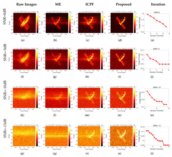
Figure 11.
Experimental results of TG-I electromagnetic simulation under different SNRs.
In contrast, the proposed algorithm can realize the accurate compensation for high-speed target motion at −13 dB and achieve well-focused images. Table 7 gives the entropy of the high-speed compensated images for different algorithms at different SNRs. The table shows that the proposed algorithm performs the best, and the proposed algorithm obtains the smallest image entropy compared to the other algorithms.

Table 7.
Entropy of high-speed compensated images with different SNRs based on TG-I’s EM simulation data.
In the experiments, we found that when the SNR decreases below −13 dB, the proposed method will fail to compensate for the high-speed motion accurately, and the compensated images will be seriously blurred. To illustrate these, the RMSE curves between the estimated velocity and the true velocity for different SNRs are given, as shown in Figure 12. As one can note, the proposed method provides very small MSE only when SNR is above −13 dB, while the speed estimation errors of the other two compared methods significantly increase at SNR lower than −5 dB. When the SNR decreases below −13 dB, the RMSE of the estimated velocity becomes much more significant, which leads to blurred images. As has been mentioned before, the relationship between the focusing quality and image entropy is inconsistent when extreme noise is involved in the data. Furthermore, the entropy of the image almost relies on the strong noise only, independent of the high-speed motion compensation. In this situation, one can use more pulses to obtain high-SNR gain, and then, the well-focused images may be generated by the proposed method. In general, the proposed algorithm has good noise robustness.
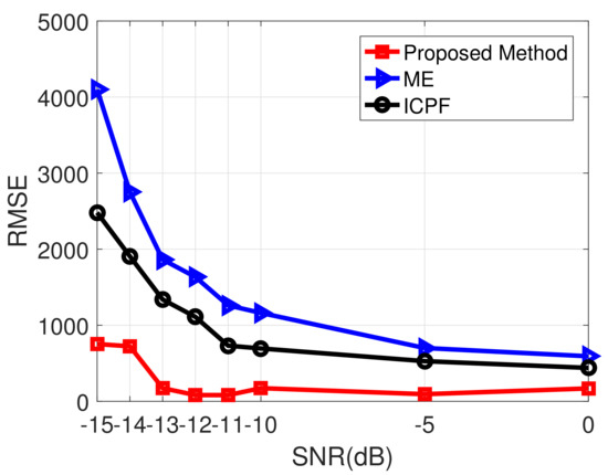
Figure 12.
RMSE under different SNRs based on EM simulation data.
4.4. Experiment Using Measured Yak-42 Data
To verify the performance of the proposed algorithm on the measured data, this section uses the Yak-42 measured data for the performance analysis of the algorithm. High-speed motion and different noise are added into the data, and the different high-speed motion compensation algorithms are performed. The dataset of the Yak-42 airplane is recorded by a C-band (5.52 GHz) ISAR experimental system. The system transmits a 400 MHz linear modulated chirp signal with 25.6 us pulse duration, providing a range resolution of 0.375 m. The de-chirp sampling rate is also 10 MHz. The SNR is up to 22 dB of the raw data. The picture of the Yak-42 aircraft is shown in Figure 13a. The standard ISAR image is shown in Figure 13b. Since the speed of the actual aircraft is relatively low (approximately 100 m/s), the speed of the aircraft itself is negligible compared to the high-speed motion of several kilometers per second. In addition, different high speed motions in Table 2 are added to the original radar echoes according to Equation (10). As in the two previous experiments, the transnational motion compensation and phase error compensation are performed first, followed by the high-speed motion compensation with different algorithms.
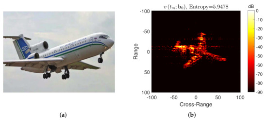
Figure 13.
(a) Yak-42 airplane and (b) its standard ISAR image.
As one can clearly see from Figure 14, compared with ME and ICPF, significantly clearer images can be achieved by using the proposed method, no matter which high-speed motions are added into the measured Yak-42 data. On the contrary, the images obtained by ME and ICPF are poor in focusing quality, although it is greatly improved compared to the images without high-speed compensation. To better show the advantage of the proposed method, Table 8 gives the image entropy after different high-speed motion compensation algorithms, as it can be seen that the proposed algorithm has the smallest image entropy after compensation, which is basically close to the entropy of the ideal image. Figure 15 gives the estimated velocity of different algorithms with respect to the real velocity, and Table 9 gives the RMSE of the estimated velocity, and it can be seen that the proposed algorithm still has the best performance on the real measured data.
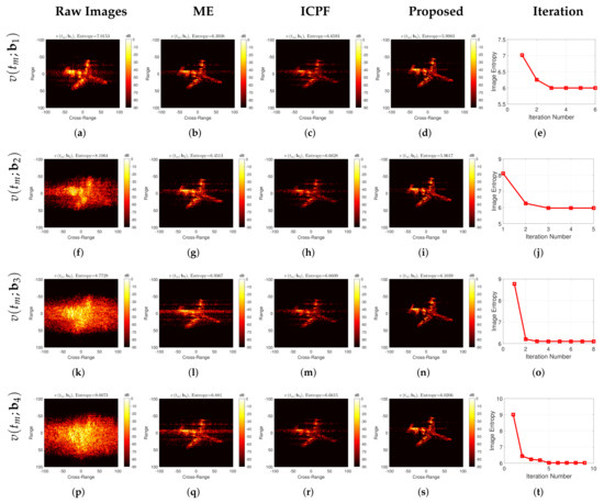
Figure 14.
Experimental results of Yak-42 measured data under different motion conditions. The leftmost column is the imaging results without high-speed motion compensation; the second column is the high-speed compensation imaging results by ME; the third column is the high-speed compensation imaging results by ICPF; the fourth column is the high-speed compensation imaging results of the proposed algorithm; the rightmost column is the image entropy against the iteration number of the proposed algorithm.

Table 8.
The entropy of images acquired by different algorithms using Yak-42 measured data.

Figure 15.
Comparison of estimated velocity and real velocity using Yak-42 measured data at different motion conditions.

Table 9.
Estimated speed RMSE of different algorithms using Yak-42 measured data.
The results of the high-speed motion compensation using Yak-42 measured data with different SNRs are given in Figure 16, and the different columns are the imaging results obtained by using different compensation algorithms. It can be seen that, similarly to the EM simulation data results, the proposed algorithm obtains well-focused images at low SNR (not lower than −13 dB), while both the ME and ICPF algorithms fail at low SNRs. Similarly, the entropies of the compensated images for different SNRs are given in Table 10. The RMSE of velocity estimation for different SNRs is also given, as shown in Figure 17. It can be seen that the proposed method performs the best.
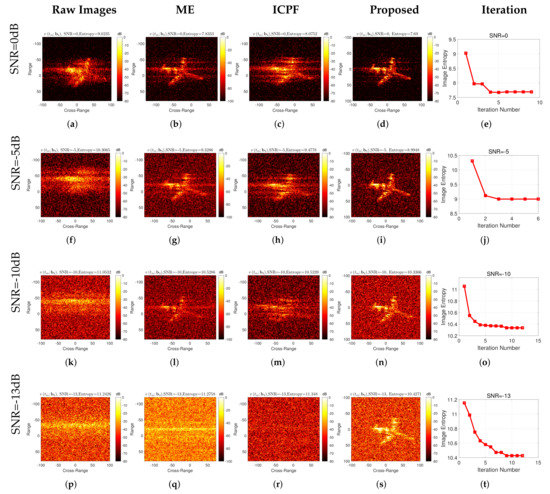
Figure 16.
Experimental results of Yak-42 measured data under different SNRs.

Table 10.
Entropy of high-speed compensated images with different SNRs based on Yak-42 measured data.
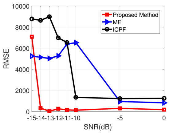
Figure 17.
RMSE under different SNRs based on Yak-42 measured data.
To reflect the speed advantage of the proposed algorithm, a comparison of the computation time of the proposed algorithm with several other algorithms is given in Table 11. The cpu time is obtained with MATLAB coding using a personal computer with an Intel Core i5 3.30-GHz processer and 8-GB memory. From the table, it can be seen that the proposed method requires only a few seconds for the computation time, while the other two compared algorithms require several hundred seconds. This is due to the fact that the proposed method compensates all the echoes within a CPI consistently, taking into account the integrity of the target motion. However, the other two algorithms process each pulse individually and require a longer computing time.

Table 11.
Computation time comparison of individual methods.
5. Conclusions
The target’s high-speed motion leads to the range profile spreading after echo pulse compression, which seriously affects the ISAR imaging and leads to severe image blurring. In addition, the low SNR of the high-speed moving target echoes has been a critical problem that plagues accurate and robust high-speed motion compensation. This paper proposes a noise-robust high-speed motion compensation algorithm for the high-speed moving target ISAR imaging under low SNR conditions. This paper innovatively considers the continuity of the target velocity variation. By transforming the velocity within a CPI into a high-order polynomial model, the proposed method establishes a parameterized minimum entropy optimization model and realizes the high-speed motion compensation for the targets by quickly and accurately searching the polynomial coefficients via the BFGS-based quasi-Newton iterative method. The proposed algorithm has promising noise robustness and can accurately compensate for the high-speed motion of the target under low SNR conditions. Different experiments verify the effectiveness of the proposed algorithm.
Author Contributions
Conceptualization and methodology, J.W. and Y.L.; software, J.W.; resources, J.W. and M.S.; writing—review and editing, J.W., Y.L., P.H. and M.X. All authors have read and agreed to the published version of the manuscript.
Funding
This work was supported in part by the National Key R&D Program of China under Grant 2018YFB2202500, in part by the National Natural Science Foundation of China (Grant No. 62171337), in part by the Key R&D program of Shaanxi Province under grant 2017KW-ZD-12, in part by the Shaanxi Province Funds for Distinguished Young youths under grant S2020-JC-JQ-0056, in part by the National Natural Science Foundation of China (Grant No. 62101396) and in part by the Fundamental Research Funds for the Central Universities (No. XJS212205).
Data Availability Statement
Not applicable.
Acknowledgments
The authors would like to thank all reviewers and editors for their comments on this paper.
Conflicts of Interest
The authors declare no conflict of interest.
References
- Walker, J.L. Range-Doppler imaging of rotating objects. IEEE Trans. Aerosp. Electron. Syst. 1980, AES-16, 23–52. [Google Scholar] [CrossRef]
- Xu, G.; Xing, M.D.; Zhang, L.; Duan, J.; Chen, Q.Q.; Bao, Z. Sparse apertures ISAR imaging and scaling for maneuvering targets. IEEE J. Sel. Top. Appl. Earth Obs. Remote Sens. 2014, 7, 2942–2956. [Google Scholar] [CrossRef]
- Yang, L.; Xing, M.; Zhang, L.; Sun, G.C.; Gao, Y.; Zhang, Z.; Bao, Z. Integration of rotation estimation and high-order compensation for ultrahigh-resolution microwave photonic isar imagery. IEEE Trans. Geosci. Remote Sens. 2020, 59, 2095–2115. [Google Scholar] [CrossRef]
- Ma, J.T.; Gao, M.G.; Guo, B.F.; Dong, J.; Xiong, D.; Feng, Q. High resolution inverse synthetic aperture radar imaging of three-axis-stabilized space target by exploiting orbital and sparse priors. Chin. Phys. B 2017, 26, 108401. [Google Scholar] [CrossRef]
- Jakowatz, C.V.; Wahl, D.E.; Eichel, P.H.; Ghiglia, D.C.; Thompson, P.A. Spotlight-Mode Synthetic Aperture Radar: A Signal Processing Approach: A Signal Processing Approach; Springer: Berlin/Heidelberg, Germany, 2012. [Google Scholar]
- Chen, C.C.; Andrews, H.C. Target-motion-induced radar imaging. IEEE Trans. Aerosp. Electron. Syst. 1980, AES-16, 2–14. [Google Scholar] [CrossRef]
- Caputi, W.J. Stretch: A time-transformation technique. IEEE Trans. Aerosp. Electron. Syst. 1971, AES-7, 269–278. [Google Scholar] [CrossRef]
- Wehner, D.R. High resolution radar. In Norwood; Artech House: London, UK, 1987. [Google Scholar]
- Tian, B.; Chen, Z.; Xu, S.; Liu, Y. ISAR imaging compensation of high speed targets based on integrated cubic phase function. In MIPPR 2013: Multispectral Image Acquisition, Processing, and Analysis; International Society for Optics and Photonics: Bellingham, WA, USA, 2013; Volume 8917, p. 89170B. [Google Scholar]
- Kun-Fan, Z.; Zhi-Hong, F.; De-Bao, M. Study on a method of compensation for the range profile of high velocity spatial targets. In Proceedings of the 2010 International Conference on Image Analysis and Signal Processing, Zhejiang, China, 9–11 April 2010; pp. 450–453. [Google Scholar]
- Tian, B.; Lu, Z.; Liu, Y.; Li, X. High velocity motion compensation of IFDS data in ISAR imaging based on adaptive parameter adjustment of matched filter and entropy minimization. IEEE Access 2018, 6, 34272–34278. [Google Scholar] [CrossRef]
- Gu, F.F.; Fu, M.H.; Chen, C.H.; Yang, M.; Zhang, Y. A novel ISAR imaging method for high speed moving target based on parametric sparse representation. In Proceedings of the 2017 16th International Conference on Optical Communications and Networks (ICOCN), Wuzhen, China, 7–10 August 2017; pp. 1–3. [Google Scholar]
- Zhiping, Y.; Zhen, F.; Dongjin, W.; Weidong, C. ISAR imaging of fast-moving target based on FRFT range compression. In Proceedings of the 2007 1st Asian and Pacific Conference on Synthetic Aperture Radar, Huangshan, China, 5–9 November 2007; pp. 306–309. [Google Scholar]
- Cao, M.; Fu, Y.; Jiang, W.; Li, X.; Zhuang, Z. High resolution range profile imaging of high speed moving targets based on fractional Fourier transform. In MIPPR 2007: Automatic Target Recognition and Image Analysis; and Multispectral Image Acquisition; International Society for Optics and Photonics: Bellingham, WA, USA, 2007; Volume 6786, p. 678654. [Google Scholar]
- Zhang, S.; Sun, S.; Zhang, W.; Zong, Z.; Yeo, T.S. High-resolution bistatic ISAR image formation for high-speed and complex-motion targets. IEEE J. Sel. Top. Appl. Earth Obs. Remote Sens. 2015, 8, 3520–3531. [Google Scholar] [CrossRef]
- Wang, F.; Jiang, D.; Chen, H. High range resolution profile construction exploiting modified fractional Fourier transformation. Math. Probl. Eng. 2015, 2015, 321878. [Google Scholar] [CrossRef] [Green Version]
- Liu, Y.; Zhang, S.; Zhu, D.; Li, X. A novel speed compensation method for ISAR imaging with low SNR. Sensors 2015, 15, 18402–18415. [Google Scholar] [CrossRef] [Green Version]
- Wang, Y.; Kang, J.; Jiang, Y. ISAR imaging of maneuvering target based on the local polynomial Wigner distribution and integrated high-order ambiguity function for cubic phase signal model. IEEE J. Sel. Top. Appl. Earth Obs. Remote Sens. 2014, 7, 2971–2991. [Google Scholar] [CrossRef]
- Brinkman, W.; Thayaparan, T. Focusing ISAR images using the AJTF optimized with the GA and the PSO algorithm-comparison and results. In Proceedings of the 2006 IEEE Conference on Radar, Verona, NY, USA, 24–27 April 2006. [Google Scholar]
- He, C.; Daiying, Z. High speed motion compensation based on the range profile. In Proceedings of the 2013 IEEE International Conference on Signal Processing, Communication and Computing (ICSPCC 2013), Kunming, China, 5–8 August 2013; pp. 1–4. [Google Scholar]
- Sheng, J.; Fu, C.; Wang, H.; Liu, Y. High speed motion compensation for terahertz ISAR imaging. In Proceedings of the 2017 International Applied Computational Electromagnetics Society Symposium (ACES), Suzhou, China, 1–4 August 2017; pp. 1–2. [Google Scholar]
- Guo, B.; Li, Z.; Xiao, Y.; Shi, L.; Han, N.; Zhu, X. ISAR Speed Compensation Algorithm for High-speed Moving Target Based on Simulate Anneal. In Proceedings of the 2019 IEEE 19th International Conference on Communication Technology (ICCT), Xi’an, China, 16–19 October 2019; pp. 1595–1599. [Google Scholar]
- Zhu, D.; Wang, L.; Yu, Y.; Tao, Q.; Zhu, Z. Robust ISAR range alignment via minimizing the entropy of the average range profile. IEEE Geosci. Remote Sens. Lett. 2009, 6, 204–208. [Google Scholar]
- Liu, L.; Zhou, F.; Tao, M.; Sun, P.; Zhang, Z. Adaptive translational motion compensation method for ISAR imaging under low SNR based on particle swarm optimization. IEEE J.Sel. Top. Appl. Earth Obs. Remote Sens. 2015, 8, 5146–5157. [Google Scholar] [CrossRef]
- Zhang, L.; Sheng, J.l.; Duan, J.; Xing, M.D.; Qiao, Z.J.; Bao, Z. Translational motion compensation for ISAR imaging under low SNR by minimum entropy. EURASIP J. Adv. Signal Process. 2013, 2013, 33. [Google Scholar] [CrossRef] [Green Version]
- Xi, L.; Guosui, L.; Ni, J. Autofocusing of ISAR images based on entropy minimization. IEEE Trans. Aerosp. Electron. Syst. 1999, 35, 1240–1252. [Google Scholar] [CrossRef]
- Wang, J.; Liu, X.; Zhou, Z. Minimum-entropy phase adjustment for ISAR. IEE Proc.-Radar Sonar Navig. 2004, 151, 203–209. [Google Scholar] [CrossRef]
- Kragh, T.J.; Kharbouch, A.A. Monotonic iterative algorithm for minimum-entropy autofocus. In Proceedings of the Adaptive Sensor Array Processing (ASAP) Workshop, Lexington, KY, USA, 6–7 June 2006; Volume 40, pp. 1147–1159. [Google Scholar]
- Wang, J.; Zhang, L.; Du, L.; Yang, D.; Chen, B. Noise-robust motion compensation for aerial maneuvering target ISAR imaging by parametric minimum entropy optimization. IEEE Trans. Geosci. Remote Sens. 2019, 57, 4202–4217. [Google Scholar] [CrossRef]
- Li, Y.; Wu, R.; Xing, M.; Bao, Z. Inverse synthetic aperture radar imaging of ship target with complex motion. IET Radar Sonar Navig. 2008, 2, 395–403. [Google Scholar] [CrossRef]
- Liu, Y.; Li, G.; Tian, B.; Chen, Z.P. ISAR imaging at low SNR level based on polarimetric whitening filter. In MIPPR 2013: Multispectral Image Acquisition, Processing, and Analysis; International Society for Optics and Photonics: Bellingham, WA, USA, 2013; Volume 8917, p. 891703. [Google Scholar]
- Barbarossa, S.; Di Lorenzo, P.; Vecchiarelli, P. Parameter estimation of 2D multi-component polynomial phase signals: An application to SAR imaging of moving targets. IEEE Trans. Signal Process. 2014, 62, 4375–4389. [Google Scholar] [CrossRef]
- Cantoni, A.; Martorella, M. Fourier-based ISAR imaging using 2D polynomials. IET Radar Sonar Navig. 2017, 11, 1216–1227. [Google Scholar] [CrossRef] [Green Version]
- Cantoni, A.; Martorella, M. ISAR image autofocus using 2D-polynomials. In Proceedings of the 2016 IEEE Radar Conference (RadarConf), Philadelphia, PA, USA, 2–6 May 2016; pp. 1–6. [Google Scholar]
- Nocedal, J.; Wright, S. Numerical Optimization; Springer: Berlin/Heidelberg, Germany, 2006. [Google Scholar]
- Shao, S.; Zhang, L.; Liu, H.; Zhou, Y. Spatial-variant contrast maximization autofocus algorithm for ISAR imaging of maneuvering targets. Sci. China Inf. Sci. 2019, 62, 40303. [Google Scholar] [CrossRef] [Green Version]
- Shao, S.; Zhang, L.; Liu, H.; Zhou, Y. Accelerated translational motion compensation with contrast maximisation optimisation algorithm for inverse synthetic aperture radar imaging. IET Radar Sonar Navig. 2019, 13, 316–325. [Google Scholar] [CrossRef]
- Chen, V.C.; Lipps, R. ISAR imaging of small craft with roll, pitch and yaw analysis. In Proceedings of the Record of the IEEE 2000 International Radar Conference, Alexandria, VA, USA, 12 May 2000; pp. 493–498. [Google Scholar]
- Chen, V.C.; Miceli, W. Time-varying spectral analysis for radar imaging of manoeuvring targets. IEE Proc.-Radar Sonar Navig. 1998, 145, 262–268. [Google Scholar] [CrossRef]
- Li, Y.; Xing, M.; Su, J.; Quan, Y.; Bao, Z. A new algorithm of ISAR imaging for maneuvering targets with low SNR. IEEE Trans. Aerosp. Electron. Syst. 2013, 49, 543–557. [Google Scholar] [CrossRef]
- Martorella, M.; Berizzi, F.; Haywood, B. Contrast maximisation based technique for 2-D ISAR autofocusing. IEE Proc.-Radar Sonar Navig. 2005, 152, 253–262. [Google Scholar] [CrossRef] [Green Version]
- Wang, J.; Kasilingam, D. Global range alignment for ISAR. IEEE Trans. Aerosp. Electron. Syst. 2003, 39, 351–357. [Google Scholar] [CrossRef]
- Boag, A. A fast physical optics (FPO) algorithm for high frequency scattering. IEEE Trans. Antennas Propag. 2004, 52, AES-16, 197–204. [Google Scholar] [CrossRef]
Publisher’s Note: MDPI stays neutral with regard to jurisdictional claims in published maps and institutional affiliations. |
© 2022 by the authors. Licensee MDPI, Basel, Switzerland. This article is an open access article distributed under the terms and conditions of the Creative Commons Attribution (CC BY) license (https://creativecommons.org/licenses/by/4.0/).