Article

An Effective Infrared and Visible Image Fusion Approach via Rolling Guidance Filtering and Gradient Saliency Map

1
Department of Electronic Engineering, Tsinghua University, Beijing 100084, China
2
School of Information and Electronics, Beijing Institute of Technology, Beijing 100081, China
3
College of Information Science and Engineering, Xinjiang University, Urumqi 830046, China
4
School of Mechanical Engineering, Guangxi University, Nanning 530004, China
5
Institute of Software, Chinese Academy of Sciences, Beijing 100190, China
6
State Key Laboratory of Remote Sensing Science, Aerospace Information Research Institute, Chinese Academy of Sciences, Beijing 100101, China
*
Author to whom correspondence should be addressed.
Remote Sens. 2023, 15(10), 2486; https://doi.org/10.3390/rs15102486
Submission received: 4 April 2023 / Revised: 28 April 2023 / Accepted: 4 May 2023 / Published: 9 May 2023

Abstract

:
To solve problems of brightness and detail information loss in infrared and visible image fusion, an effective infrared and visible image fusion method using rolling guidance filtering and gradient saliency map is proposed in this paper. The rolling guidance filtering is used to decompose the input images into approximate layers and residual layers; the energy attribute fusion model is used to fuse the approximate layers; the gradient saliency map is introduced and the corresponding weight matrices are constructed to perform on residual layers. The fusion image is generated by reconstructing the fused approximate layer sub-image and residual layer sub-images. Experimental results demonstrate the superiority of the proposed infrared and visible image fusion method.

1. Introduction

Infrared and visible light sensors are two kinds of commonly used imaging sensors. The infrared sensor recognizes the target by detecting the thermal radiation difference between the target and the background, and has the ability to identify camouflage, but it is not sensitive to the brightness changes of the scene [1]. Visible light imaging sensors are sensitive to the reflection of the target scene, and the acquired image is usually clear. It can accurately provide the details of the scene where the target is located, but it is vulnerable to light, weather, occlusion, and other factors. According to the respective characteristics of infrared and visible images, the fusion of the two images can make full use of information complementarity, expand the space-time coverage of system target detection, and improve the spatial resolution and target detection capability of the system [2].
There are many methods for image fusion, including multi-resolution analysis (MRA), sparse representation, deep learning, and edge-preserving filtering, etc. In terms of multi-resolution analysis-based methods [3], the Laplacian pyramid, steerable pyramid, DWT, DTCWT, ridgelet transform, contourlet transform, and shearlet transform are widely used in image fusion [4,5,6,7]. Mohan et al. [8] introduced the Laplacian pyramid into the multi-modal image fusion utilizing the quarter shift DTCWT and modified principal component analysis. The Laplacian pyramid is used to decompose the source images into low- and high-components, the quarter shift DTCWT is used to fuse the sub-bands, and the final fused image is obtained through modified principal component analysis. Vivone et al. [9] introduced the pansharpening method via the Laplacian pyramid. Liu et al. [10] introduced the early work on image fusion based on the steerable pyramid. Liu et al. [11] constructed image fusion work using DWT and stationary wavelet transform (SWT). Sulaiman et al. [12] introduced the contourlet transform into pansharpening with kernel principal component analysis and improved sum-modified Laplacian fusion rules. Huang et al. [13] introduced another pansharpening method using the contourlet transform and multiple deep neural networks. Qi et al. [14] introduced the co-occurrence analysis shearlet transform and latent low rank representation for infrared and visible image fusion. Feng et al. [15] introduced the intensity transfer and phase congruency into the shearlet domain for infrared and visible image fusion. Although these algorithms have achieved certain image fusion results, it is easy to lose detail information, and the implementation process of algorithms such as contourlet and shearlet transforms are relatively time-consuming.
Sparse representation-based methods also perform well in image fusion [16,17]. Nejati et al. [18] proposed an image fusion algorithm utilizing dictionary-based sparse representation and Markov random field optimization. Zhang et al. [19] introduced the joint sparse model with coupled dictionary learning for image fusion. The source images were presented with the common sparse component and innovation sparse comments by the over-completed coupled dictionaries; the designed new fusion rule is applied for fusing the sparse coefficients, and the fused image is obtained by using the fused coefficients and coupled dictionaries. Wang et al. [20] introduced the joint patch clustering-based adaptive dictionary and sparse representation for multi-modal image fusion, and this method is robust for dealing with infrared and visible image fusion. These image fusion algorithms utilizing sparse representation have achieved remarkable fusion results in multi-modal image processing.
Deep-learning-based image fusion algorithms have gained unprecedented development and application in recent years. Li et al. [21] introduced a meta learning-based deep framework for infrared and visible image fusion; that framework can accept the source images of different resolutions and generate a fused image of arbitrary resolution just with a single learned model. This method generates the state-of-the-art image fusion results. Cheng et al. [22] introduced a general unsupervised image fusion network based on memory units. This algorithm is applied to infrared and visible image fusion, multi-focus image fusion, multi-exposure image fusion, and multi-modal medical image fusion; qualitative and quantitative experiments on four image fusion subtasks have shown that this method has advantages over the most advanced methods. Zhang et al. [23] proposed an infrared and visible image fusion method using an entropy-based adaptive fusion module and a mask-guided convolutional neural network, and this method generates good performance in qualitative and quantitative assessments. Sun et al. [24] introduced the multiscale network for infrared and visible image fusion. This method generates state-of-the-art fusion performance. Xiong et al. [25] proposed cross-domain frequency information learning via the inception transformer for infrared and visible image fusion, and this method outperforms other fusion approaches in subject and object assessments.
In recent years, base-detail decomposition-based approaches have been introduced into image fusion by some scholars, achieving extraordinary fusion results. These methods decompose the source images into base layers and detail layers, and different fusion rules are performed on the decomposed sub-images [26,27,28]. Guided image filtering was introduced into image fusion using a weighted average strategy by Li et al. in 2013 [29]. Liu et al. [30] introduced the convolutional neural network (CNN) and nuclear norm minimization for image fusion via a rolling guidance filter (RGF). The source images are decomposed by RGF into base- and detail-information, the nuclear norm minimization-based fusion rule is applied for the detail components, and the CNN-based model is used to fuse the base components. Zou et al. [31] introduced guided filter and side window guided filter for image fusion; the visible image is enhanced by an adaptive light adjustment algorithm. This method improves the overall contrast, highlights salient targets, and retains weak details.
According to the above description, the rolling guidance filter has good application prospects in image fusion. In this paper, a novel and effective infrared and visible image fusion algorithm using rolling guidance filtering and gradient saliency map is proposed. We mainly focus on the design of fusion rules for both the approximate and residual layers. The main contributions of the proposed fusion approach are outlined as follows.
(1)
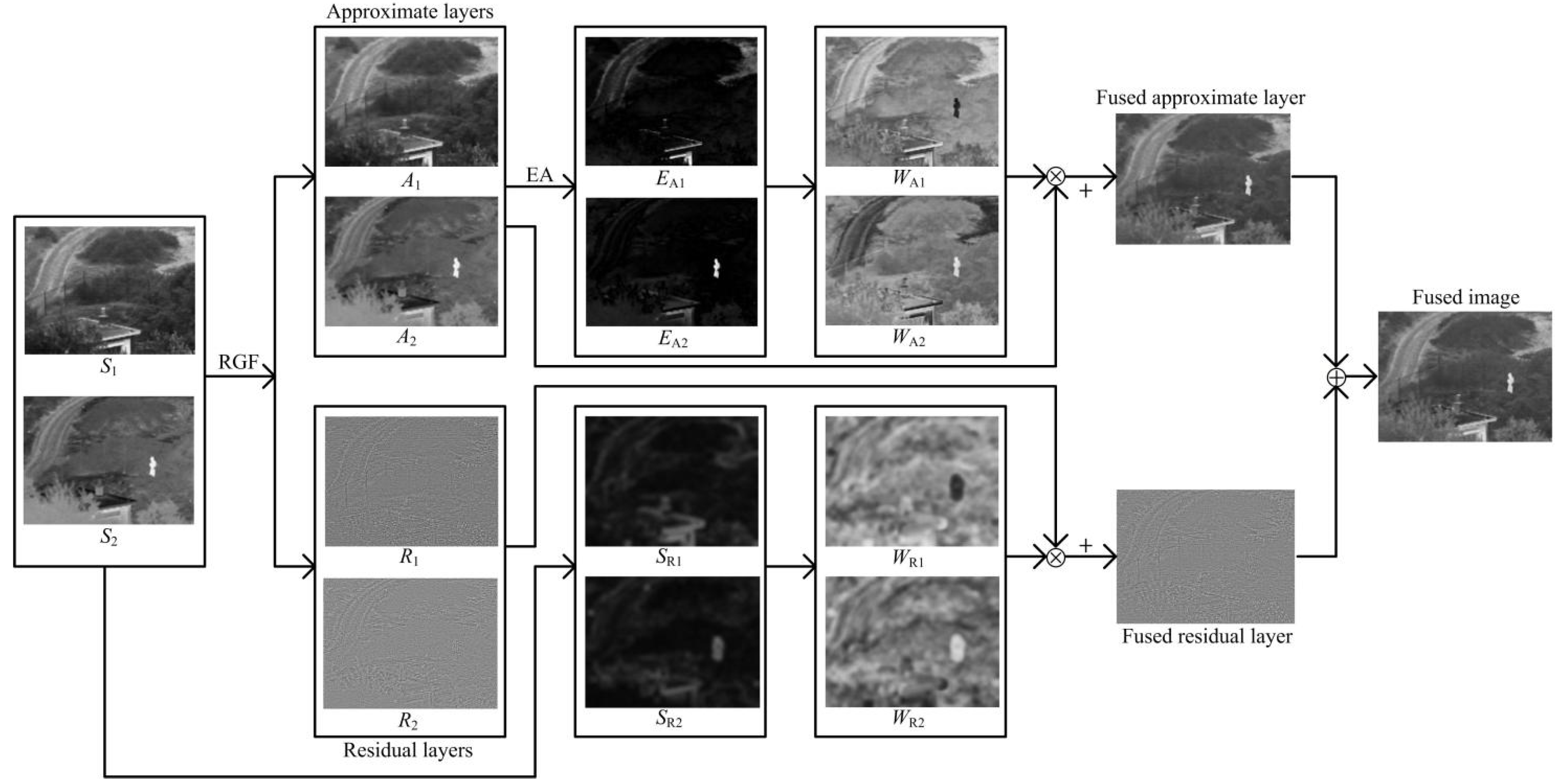
The rolling guidance filter is introduced as the decomposition structure, and the approximate and residual layers of the source images are generated.
(2)
The approximate layers contain most of the background and energy information of the source images, and the energy attribute (EA) fusion strategy is applied to fuse the approximate layers.
(3)
The residual layers contain small gradient textures and noise; the gradient saliency map and corresponding weight matrices are constructed to fuse the residual layers.
(4)
This method is superior to most fusion algorithms and provides an important approach for assisting target detection.
The rest of this paper is arranged as follows. The rolling guidance filtering is described in Section 2. The proposed method is shown in Section 3. The experimental results and discussions are given in Section 4. Finally, the conclusions and future works are presented in Section 5.

2. Rolling Guidance Filtering

Rolling guidance filtering (RGF) is an effective edge-preserving filter with fast convergence [32]. It is widely used in image fusion and image enhancement. Goyal et al. [33] proposed the multi-modal image fusion method using cross bilateral filter and rolling guidance filter. This method can generate good fusion results both visually and quantitatively. Prema et al. [34] introduced multi-scale multi-layer rolling guidance filtering for infrared and visible image fusion. The images are decomposed into micro-scale, macro-scale, and base layers; the phase-congruency-based fusion rule is used to fuse the micro-scale layers, the absolute maximum-based consistency verification fusion rule is used to fuse the macro-scale layers, and the weighted energy related fusion is used to fuse the base layers. This method can visually preserve the background and target information from the source images without pseudo and blurred edges compared to state-of-the-art fusion approaches. Chen et al. [35] proposed an image fusion technique via rolling guidance filtering and the Laplacian pyramid. The source images are separated into structural components and detail components, then the Laplacian pyramid-based model and sum-modified-Laplacian-based model are employed to fuse the structural components and detail components, respectively. This fusion method is superior to other fusion algorithms. Lin et al. [36] introduced rolling guidance filtering and saliency detection for adaptive infrared and visible image fusion technique; this method can improve the contrast and maintain details.
Firstly, the Gaussian filter is utilized to remove the small structures. The input image and output image are defined as I and G, respectively. σ s presents the standard deviation of Gaussian filter, and the filter is described as follows [32]:
G p = 1 K p q N p exp p q 2 2 σ s 2 I q
where p and q denote the pixel coordinates in the image, and K p is given by
K p = q N p exp p q 2 2 σ s 2
where N p denotes the set of neighboring pixels of p .
Secondly, the joint bilateral filter is adopted to recover the edge iteratively. The J 1 denotes the output of the Gaussian filter, 0 J t + 1 shows the output of the t-th iteration by the joint bilateral filter with the input I and previous iteration value J t . The corresponding formulas are given by:
J t + 1 p = 1 K p q N p exp p q 2 2 σ s 2 J t p J t q 2 2 σ r 2 I q
K p = q N p exp p q 2 2 σ s 2 J t p J t q 2 2 σ r 2
where K p is for normalization, σ s and σ r control the spatial and range weights, respectively.
Finally, the aforementioned two steps can be combined into one by starting rolling guidance simply from a constant-value image. Supposing that J t is constant C, then the J t + 1 is updated by the following:
J t + 1 p = 1 K p q N p exp p q 2 2 σ s 2 I q
In this paper, the filtered image U is defined as follows:
U = R G F I , σ s , σ r , T
where T denotes the number of iterations.

3. The Proposed Method

In this section, a novel infrared and visible image fusion technique based on rolling guidance filtering and gradient saliency map is proposed, and the structure of the proposed algorithm can be divided into four steps: image decomposition, approximate layer fusion, residual layer fusion, and image reconstruction. The flow-process diagram of the proposed method is shown in Figure 1.
  • Step 1. Image decomposition
The source images S n are decomposed by the rolling guidance filtering, and the approximate layers A n and residual layers R n can be given by:
A n = R G F I , σ s , σ r , T
R n = S n A n
where n 1 , 2 denotes the n-th image.
  • Step 2. The approximate layer fusion
The approximate layers present the brightness, energy information, and contrast information of the source images [37,38]. In this section, an energy attribute (EA) fusion model is applied to the approximate layers. The intrinsic property values of the approximate layers are calculated by:
I P A 1 = ( μ A 1 + M e A 1 ) / 2
I P A 2 = ( μ A 2 + M e A 2 ) / 2
where μ and M e show the mean value and the median value of A 1 and A 2 , respectively.
The EA function E A 1 and E A 2 are achieved by:
E A 1 x , y = exp a A 1 x , y I P A 1
E A 2 x , y = exp a A 2 x , y I P A 2
where exp shows the exponential operator, and a shows the modulation parameter.
The weight maps W A 1 and W A 2 are computed by:
W A 1 = E A 1 E A 1 + E A 2
W A 2 = E A 2 E A 1 + E A 2
The fused approximate layer is computed by the weighted mean:
F A = W A 1 × A 1 + W A 2 × A 2
where F A represents the fused approximate layer.
  • Step 3. The residual layer fusion
The residual layers contain the texture information and some noise of the input images, reflecting the changes of the small gradient so that the gradient saliency maps of residual layers based on the image gradient can be introduced; then, the multi-scale morphological gradient (MSMG) [39] is utilized to construct gradient maps. Compared to residual layers, the input source images has a smaller proportion of noise, so the multi-scale morphological gradient is adopted to obtain gradient features from the input images S n , generating the gradient graphs M S M G n . It can preserve the texture information, and the effect of noise can be reduced effectively. The detail steps of MSMG are as follows:
Firstly, the multi-scale structuring elements are computed by:
S E j = S E 1 S E 1 S E 1 j , j 1 ,   2 n
where S E 1 shows the basic structuring element with radius r , and n shows the number of scales.
Secondly, the gradient features G j can be calculated by the morphological gradient operator from image S , and the corresponding equation is defined as follows:
G j x , y = S x , y S E j S x , y Θ S E j , j 1 ,   2 n
where and Θ present the morphological dilation and erosion operators, respectively. They are defined as follows:
S S E = max u , v S x u , y v + S E u , v
S Θ S E = min u , v S x + u , y + v S E u , v
where x , y and u , v show the pixel coordinate in the image and structuring element, respectively.
Thirdly, MSMG is generated by integrating gradients of all scales, and it is defined as follows:
M S M G x , y = j = 1 n w j G j x , y
where w j denotes the weight for the gradients at scale j , and it is defined as follows:
w j = 1 2 × j + 1
In order to expand the influence range of the gradient on weight and achieve the final gradient saliency maps S R n , the Gaussian filter is utilized to diffuse the generated gradient images M S M G n . The corresponding equation is defined as follows:
S R n = G a u s s i a n M S M G n , δ , r
where G a u s s i a n denotes the Gaussian filter; δ and r present the standard deviation and the radius of Gaussian template, respectively. In this section, δ and r are set to 5.
For the saliency maps S R n of residual layers, the weight maps W R 1 and W R 2 of residual layers are calculated by the following:
W R 1 = S R 1 S R 1 + S R 2
W R 2 = S R 2 S R 1 + S R 2
The fused residual layers are computed by the following:
F R = W R 1 × R 1 + W R 2 × R 2
where F R represents the fused residual layer.
  • Step 4. Image reconstruction
The fused image F is generated by integrating the fused approximate and residual layers, and the corresponding equation is given by:
F = F A + F R

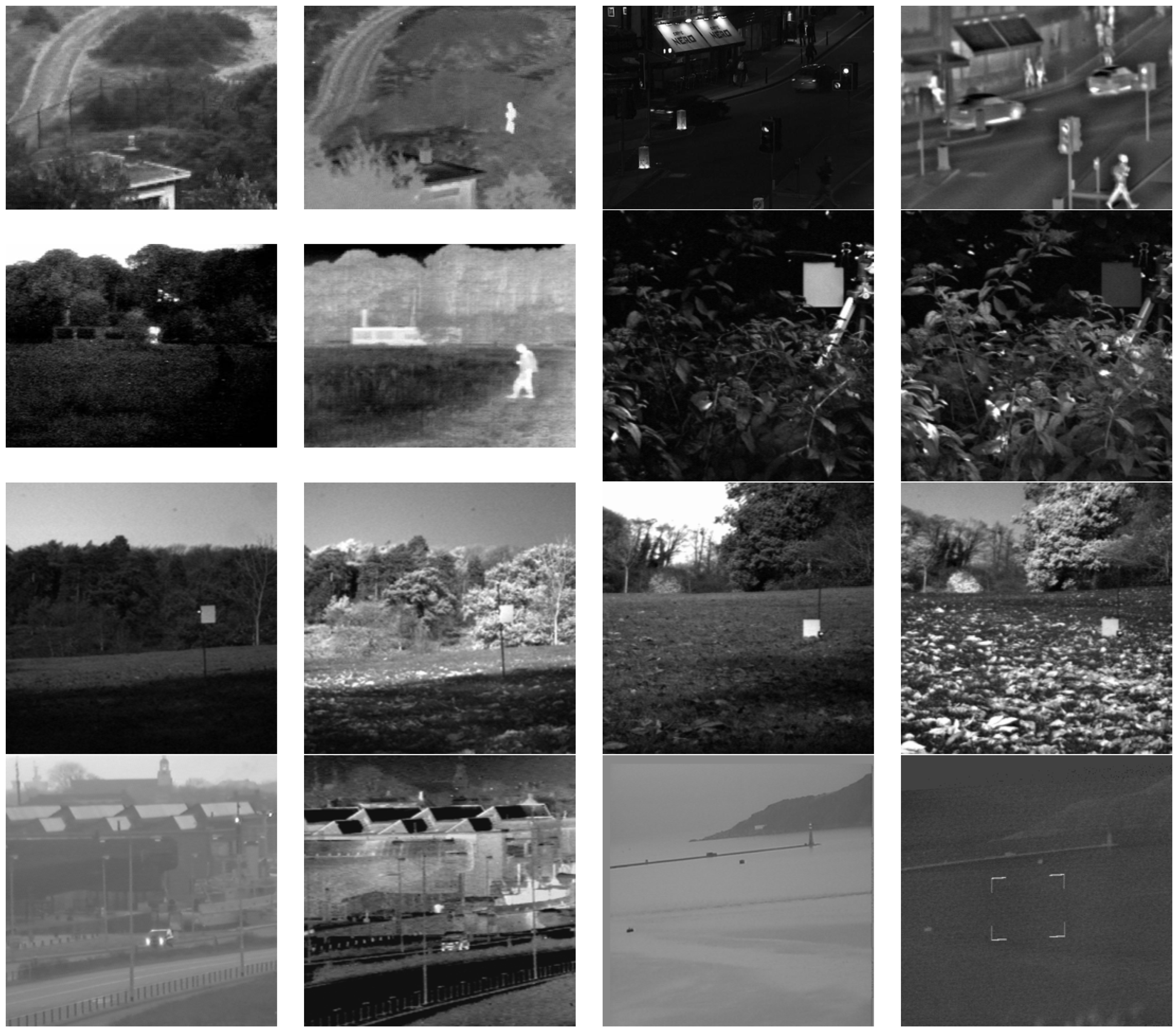
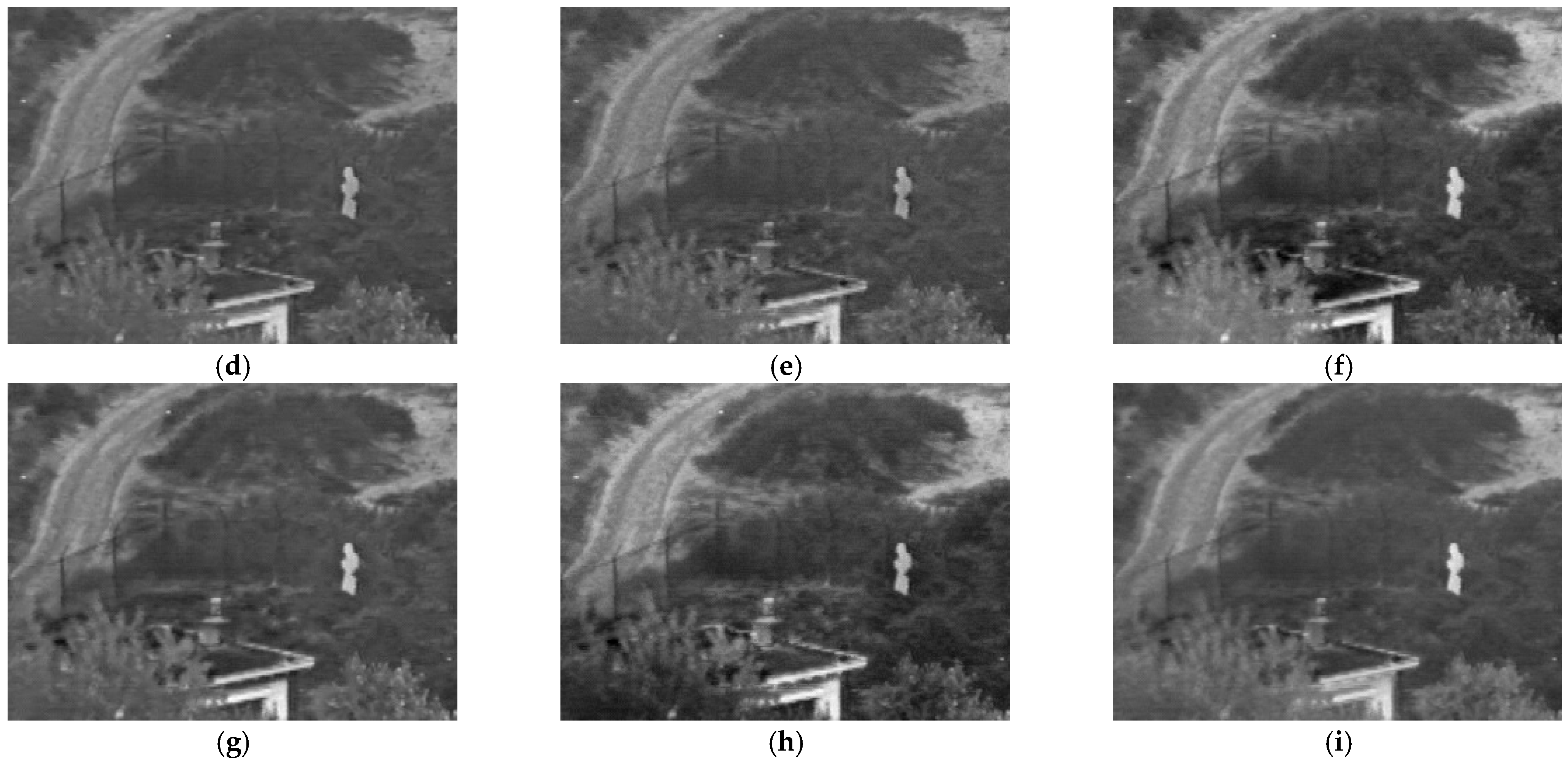
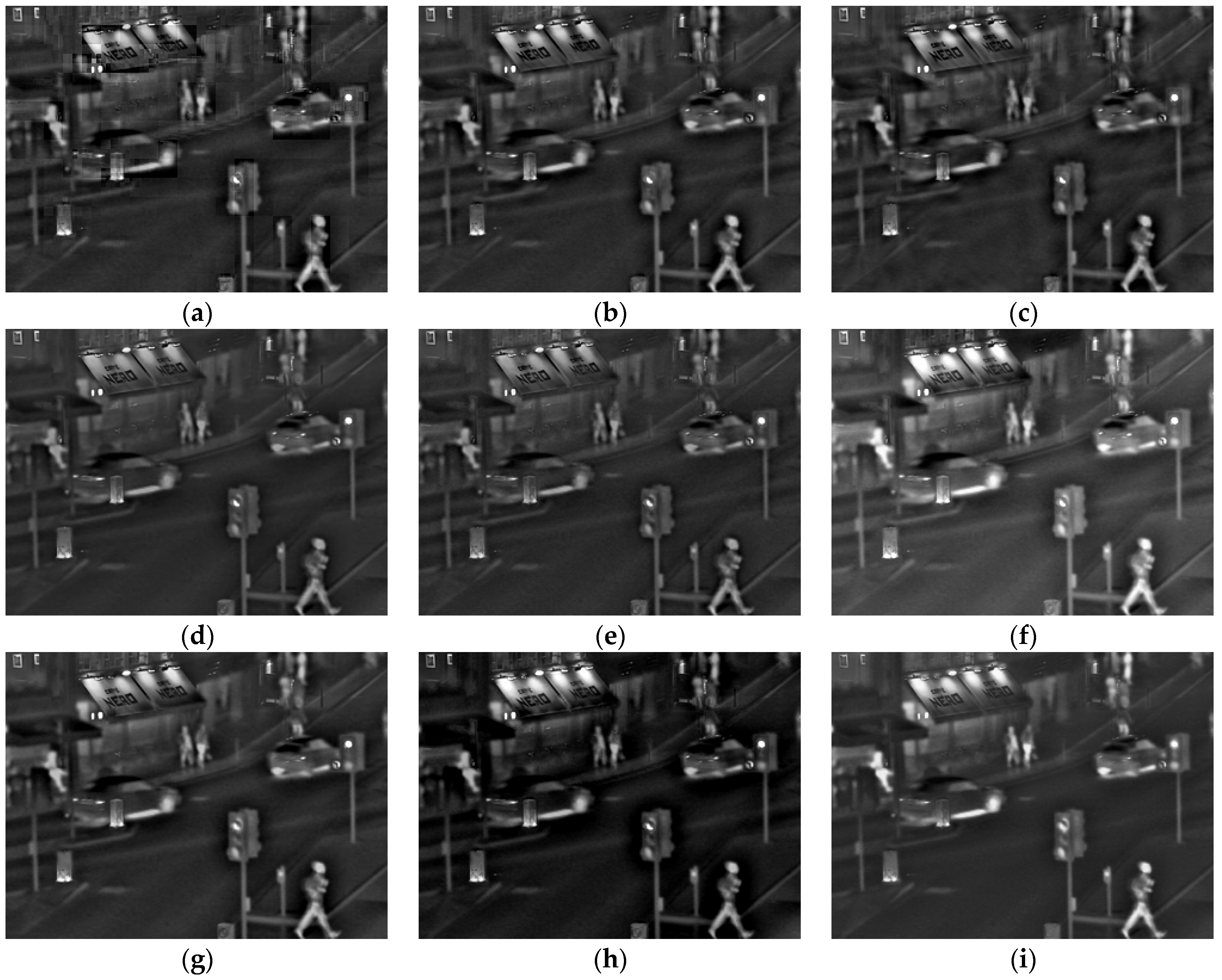
4. Experimental Results and Discussion

In order to verify the effectiveness of the proposed infrared and visible image fusion approach in this paper, we selected eight groups of infrared and visible images collected by Liu et al. [40] to test, and the corresponding datasets as shown in Figure 2. The eight image fusion algorithms are selected to compare with our method, which includes DWT [40], DTCWT [40], CVT [40], CSR [41], WLS [42], CNN [43], CSMCA [44], and TEMST [45]. In our framework, the parameters σ s , σ r and T are set to 1, 0.05, and 3, respectively. All the experiments were run on Matlab2018b.
We used subjective and objective evaluation assessments to analyze the fusion results. In terms of the objective evaluation, the following six evaluation metrics are used, which includes mutual information (QMI) [46,47,48], the human perception inspired metric (QCB) [49], nonlinear correlation information entropy (QNCIE) [50], the sum of the correlations of differences (QSCD) [51], average pixel intensity (QAPI) [52,53], and standard deviation (QSD) [53,54]. The larger the values of the six metrics, the better fusion performance there will be. The experiment results and metrics data are shown in Figure 3, Figure 4, Figure 5, Figure 6 and Figure 7 and Table 1, respectively.

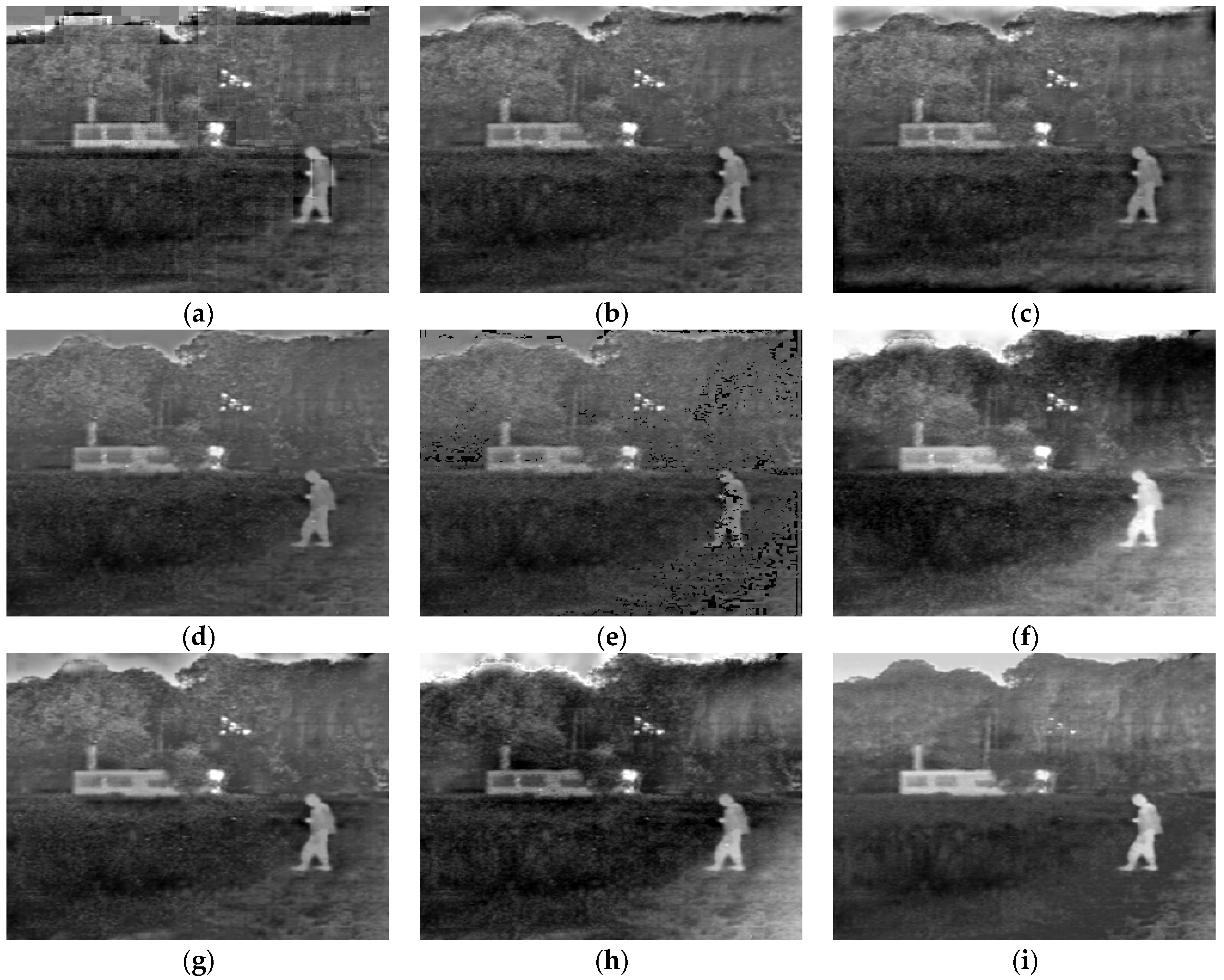
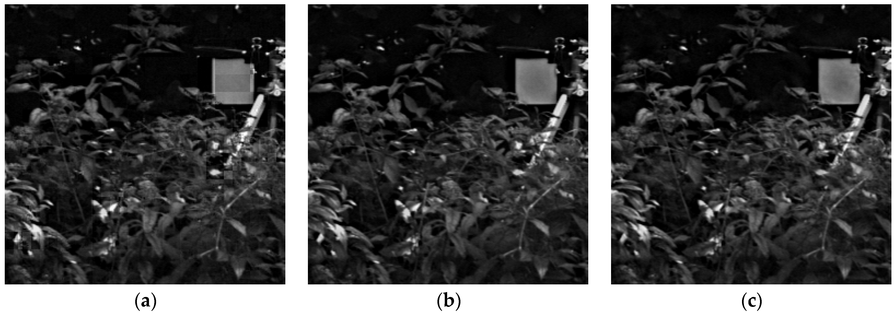
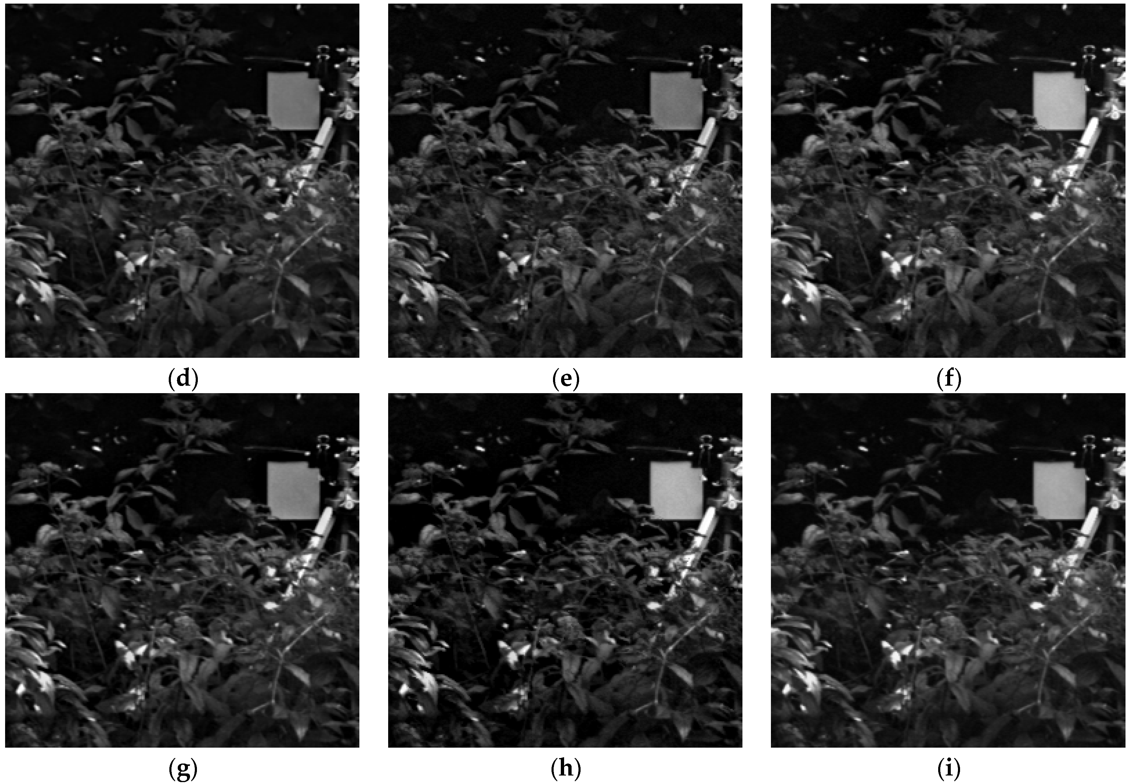
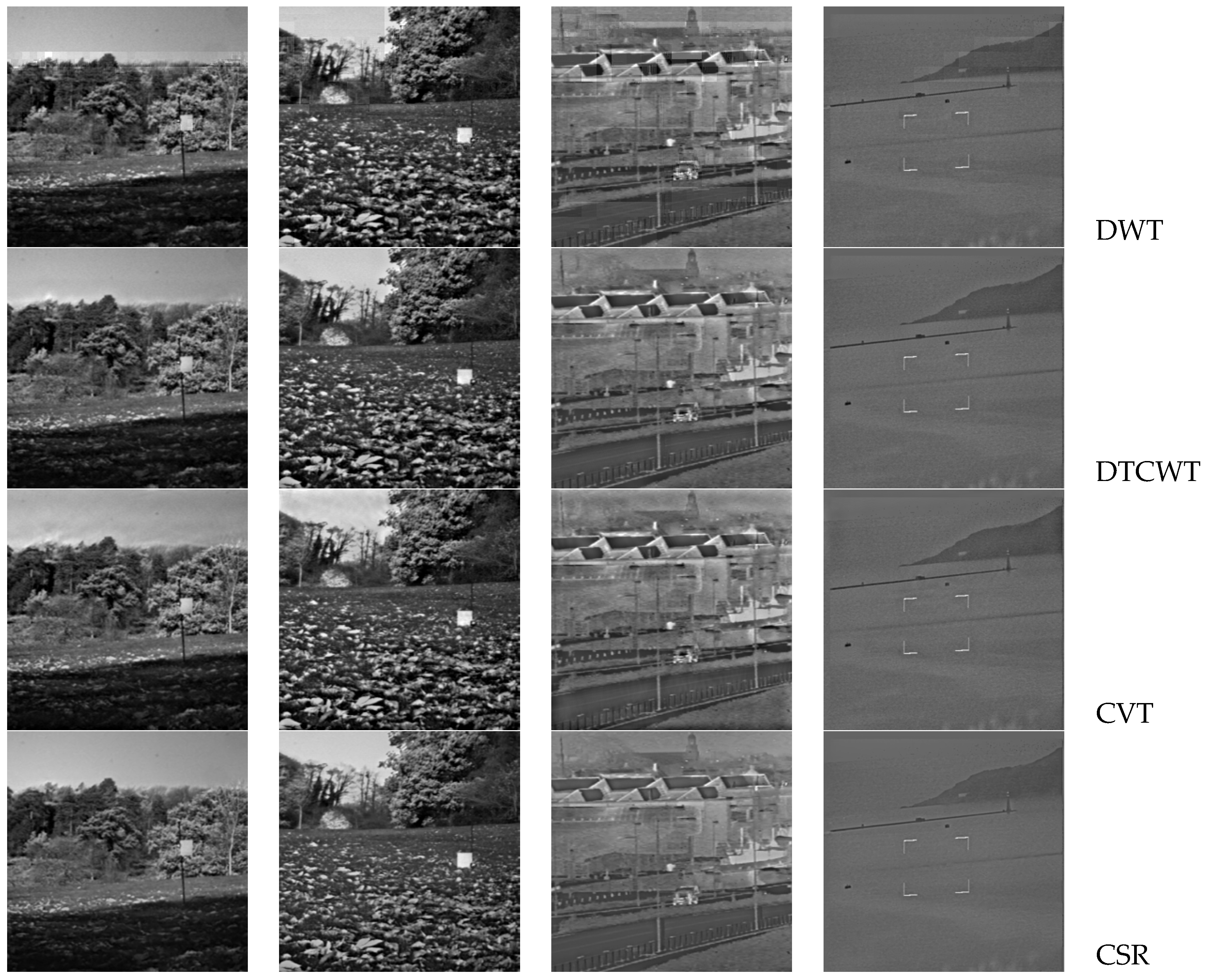
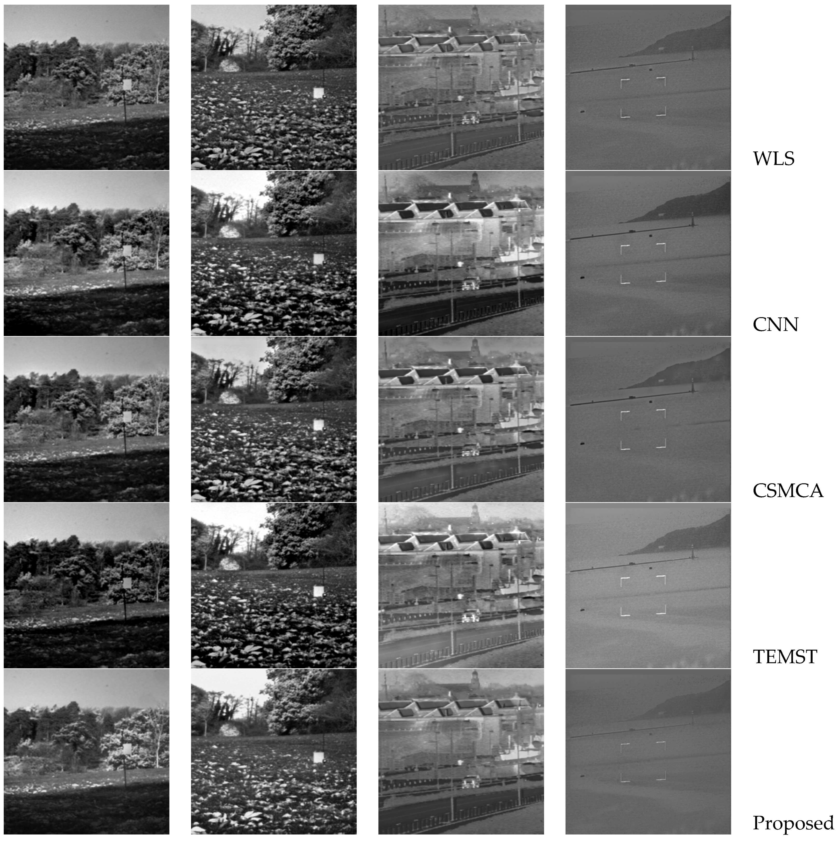
4.1. Subjective Evaluation

In this section, we will compare the subjective visual effect of the fused images, and Figure 3, Figure 4, Figure 5, Figure 6 and Figure 7 depict the fusion results. Figure 3 denotes the fused images of different methods simulated on the first group of images in Figure 2. From the results, we can notice that all fused images can depict the basic information of the scene, but the DWT method causes the blocking effect. The DTCWT and CVT methods are similar, but the surroundings of the target person in the scene are dark; the image fusion effects of the CSR and WLS methods are poor, and some information is lost. The CNN and CSMCA methods perform well in brightness preservation, and the TEMST method also achieves a certain fusion effect. Our method has an obvious effect on preserving the human body contour and the scene’s details.
Figure 4 shows the fusion images of different approaches simulated on the second group of images in Figure 2. From the fused images, we can see that all fusion image methods can basically express the basic information of the scene, including people, cars, street buildings, etc. The DWT algorithm generates the blocking effect and seriously affects information acquisition in the fused image; the fusion effects of the DTCWT and CVT algorithms are similar, but there is obviously incomplete fusion at the street lamp and the fork. The images generated by the CSR and WLS algorithms are dark, and some brightness information is lost; there are some shadows around people in the image generated by the CNN method. The image generated by the CSMCA algorithm is very dark, and the heat source object in the scene is not obvious; although the brightness information of the heat source object is maintained in the image computed by the TEMST, black blocks appear in some areas of the scene, and some important information is lost. The proposed method has a moderate brightness and clear texture, it is easy to observe the feature information, and the scene information is easy to interpret.
Figure 5 depicts the fused results of different methods simulated on the third group of images in Figure 2. From the results, we can notice that the DWT has a distortion and blocking effect. The DTCWT, CVT, CSR, and CNN generate artifacts, especially at the upper edge of the trees in the scene. The WLS has multiple black spots, poor visual effect and serious information loss. The CSMCA generates a dark fusion image, and it is difficult to capture and observe the person and object information in the scene. The TEMST produces some artifacts, and some areas are dark. Our method has moderate brightness, clear textures, and an easier access to information in the scene.
Figure 6 depicts the fused results of different methods simulated on the fourth group of images in Figure 2. From the results, we can notice that the DWT, DTCWT, and CVT generate the blocking effect and dark regions; the CSR, WLS, CNN, and CSMCA are similar, however, there are still some dark areas that are not easy to observe in detail. The image generated by TEMST is generally dark, including information such as leaves that are difficult to observe, and some information is severely lost. Our method has moderate brightness, clear textures, and an easier access to information in the scene.
Figure 7 depicts the experimental results of different fusion approaches on other infrared and visible images in Figure 2. From top to bottom, the fusion results are DWT, DTCWT, CVT, CSR, WLS, CNN, CSMCA, TEMST, and the proposed method. The experimental results demonstrate that the proposed fusion model has the advantages of maintaining brightness and detailed information.

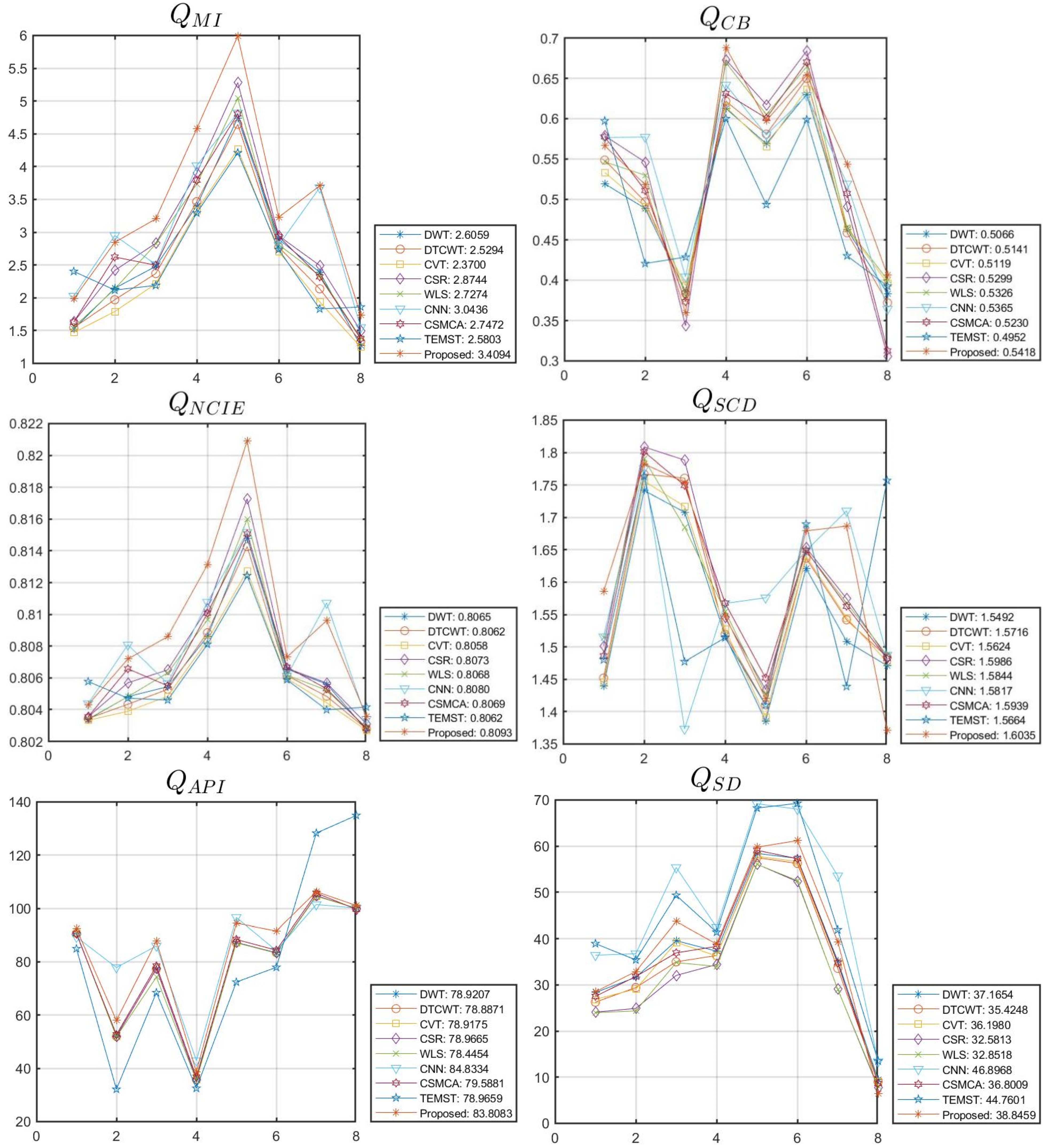
4.2. Objective Evaluation

In this section, the six metrics are used to evaluate the fusion effects objectively. For each indicator, the indicator scores obtained from different source images using the same fusion model simulation experiment are connected to generate a curve, and the average index value is given on the right side of the legend. From Figure 8, we can conclude that different methods have basically the same change trend in the given measurement. From Table 1, we can conclude that the average value of the metrics QMI, QCB, QNCIE, and QSCD computed by the proposed infrared and visible image fusion approach are the best, and that the average value of the metrics QAPI and QSD achieved by the proposed method also gains obvious results compared to other state-of-the-art algorithms.

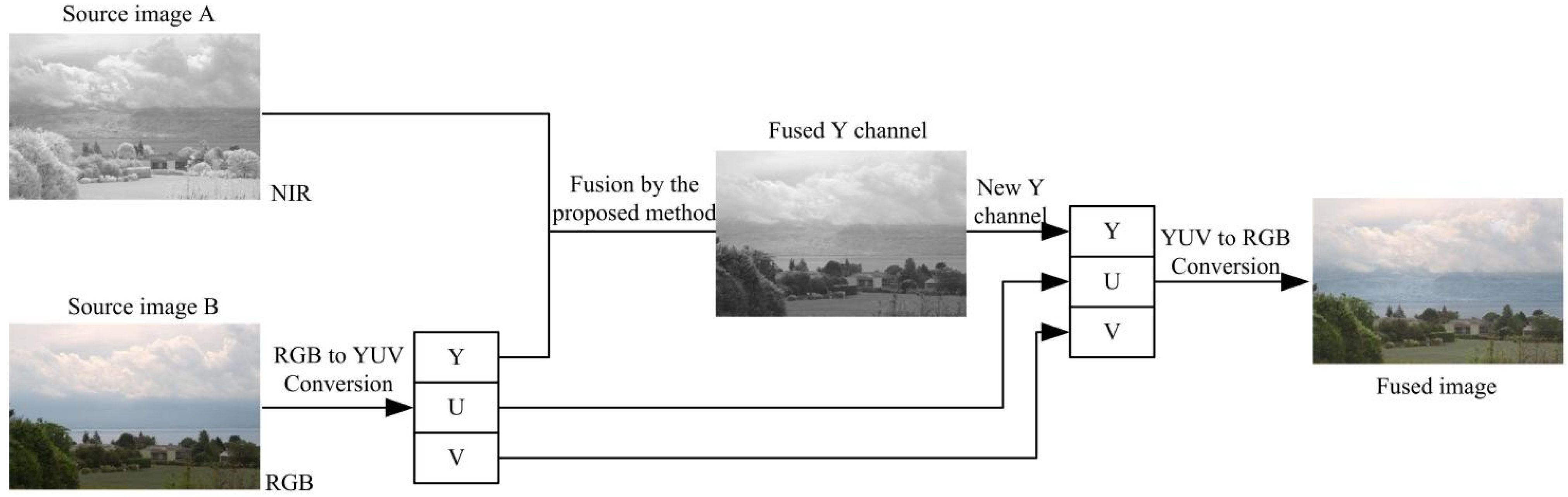
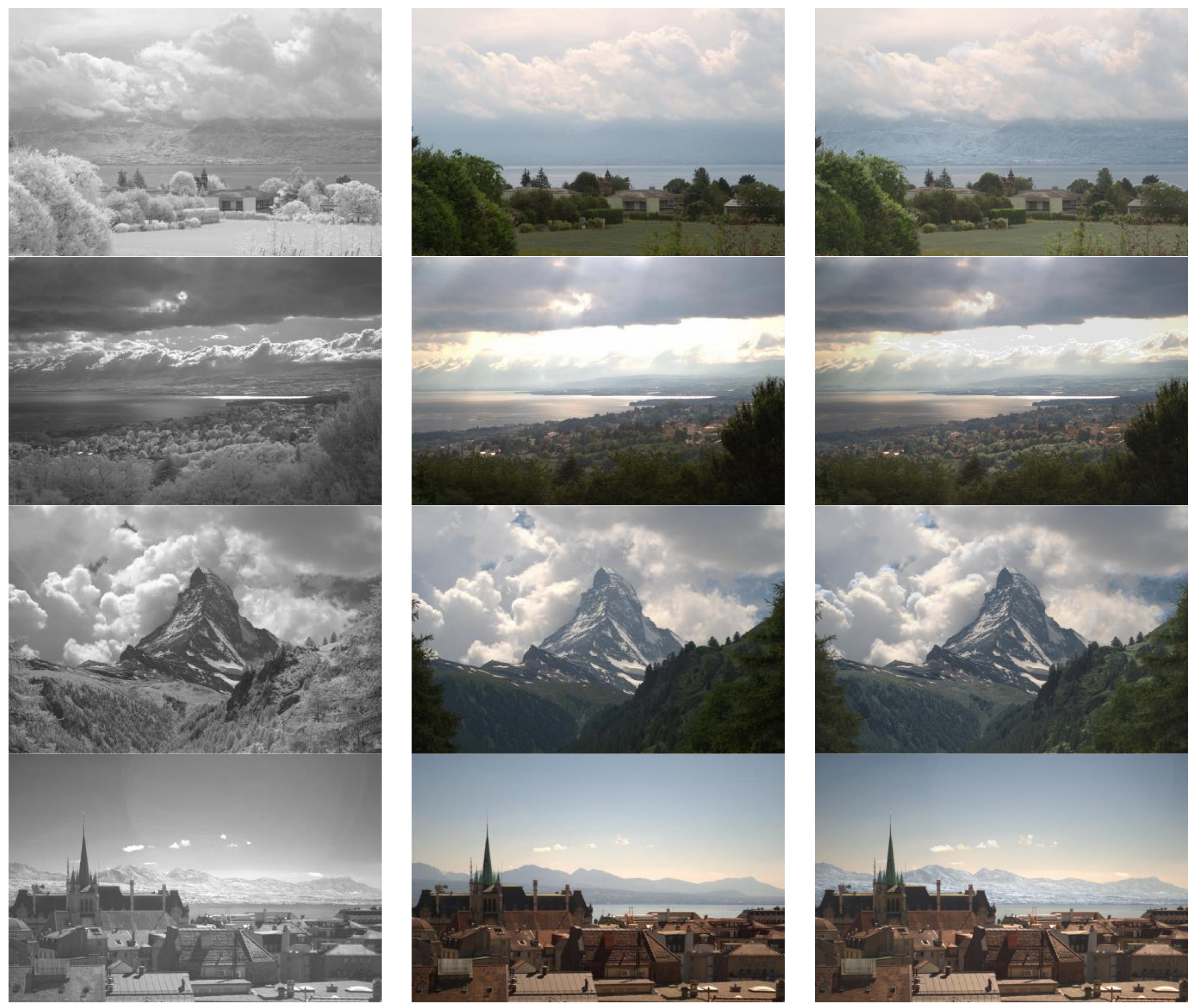
4.3. Application on RGB and Near-Infrared Fusion

In this section, we will extend the proposed method to fuse the RGB and near-infrared images, and the flow chart of the algorithm is shown in Figure 9. The color space conversion between RGB and YUV is applied here. Some experimental results generated by the proposed method are shown in Figure 10. The source images are provided by Vanmali et al., in reference [55]. From the results, we can denote that the proposed method can improve scene visibility, contrast and color perception.

5. Conclusions

This paper introduces an effective infrared and visible image fusion algorithm based on rolling guidance filtering and multi-scale morphological gradients. We constructed the energy attribute fusion model for approximate layers, and the gradient saliency map and weight matrices are constructed to perform on residual layers. In the end, the fusion image can be generated by superposing the fused approximate and residual layers. The experimental results demonstrate good performance and effectiveness compared to other state-of-the art fusion algorithms. We also extended this algorithm to fuse the RGB and near-infrared images demonstrating the effectiveness of improving contrast and color perception. In future work, we will expand the application of this algorithm to multi-focus image fusion, multi-exposure fusion, as well as medical image fusion [56,57,58]. Additionally, due to the good application of convolutional neural networks [59] in image fusion, we will consider the combination of edge-preserving filtering and deep learning in multi-modal image fusion.

Author Contributions

The experimental measurements and data collection were carried out by L.L. and H.M. The manuscript was written by L.L. with the assistance of M.L. (Ming Lv), Z.J., Q.J., M.L. (Minqin Liu), L.C. and H.M. All authors have read and agreed to the published version of the manuscript.

Funding

This work was supported by the Cross-Media Intelligent Technology Project of Beijing National Research Center for Information Science and Technology (BNRist) under Grant No. BNR2019TD01022.

Institutional Review Board Statement

Not applicable.

Informed Consent Statement

Not applicable.

Data Availability Statement

Not applicable.

Conflicts of Interest

The authors declare no conflict of interest.

References

  1. Ma, J.; Ma, Y.; Li, C. Infrared and visible image fusion methods and applications: A survey. Inf. Fusion 2019, 45, 153–178. [Google Scholar] [CrossRef]
  2. Xu, X.; Shen, Y.; Han, S. Dense-FG: A fusion GAN model by using densely connected blocks to fuse infrared and visible images. Appl. Sci. 2023, 13, 4684. [Google Scholar] [CrossRef]
  3. Liu, Y.; Wang, L.; Chen, J. Multi-focus image fusion: A Survey of the state of the art. Inf. Fusion 2020, 64, 71–91. [Google Scholar] [CrossRef]
  4. Liu, Y.; Chen, X.; Wang, Z. Deep learning for pixel-level image fusion: Recent advances and future prospects. Inf. Fusion 2018, 42, 158–173. [Google Scholar] [CrossRef]
  5. Karim, S.; Tong, G.; Li, J. Current advances and future perspectives of image fusion: A comprehensive review. Inf. Fusion 2023, 90, 185–217. [Google Scholar] [CrossRef]
  6. Li, S.; Kang, X.; Fang, L. Pixel-level image fusion: A survey of the state of the art. Inf. Fusion 2017, 33, 100–112. [Google Scholar] [CrossRef]
  7. Li, L.; Wang, L.; Wang, Z. A novel medical image fusion approach based on nonsubsampled shearlet transform. J. Med. Imaging Health Inform. 2019, 9, 1815–1826. [Google Scholar] [CrossRef]
  8. Mohan, C.; Chouhan, K.; Rout, R. Improved procedure for multi-focus images using image fusion with qshiftN DTCWT and MPCA in Laplacian pyramid domain. Appl. Sci. 2022, 12, 9495. [Google Scholar] [CrossRef]
  9. Vivone, G.; Marano, S.; Chanussot, J. Pansharpening: Context-based generalized Laplacian pyramids by robust regression. IEEE Trans. Geosci. Remote Sens. 2020, 58, 6152–6167. [Google Scholar] [CrossRef]
  10. Liu, Z.; Tsukada, K.; Hanasaki, K. Image fusion by using steerable pyramid. Pattern Recognit. Lett. 2001, 22, 929–939. [Google Scholar] [CrossRef]
  11. Liu, S.; Chen, J.; Rahardja, S. A new multi-focus image fusion algorithm and its efficient implementation. IEEE Trans. Circuits Syst. Video Technol. 2020, 30, 1374–1384. [Google Scholar] [CrossRef]
  12. Sulaiman, A.; Elashmawi, W.; Eltaweel, G. IHS-based pan-sharpening technique for visual quality improvement using KPCA and enhanced SML in the NSCT domain. Int. J. Remote Sens. 2021, 42, 537–566. [Google Scholar] [CrossRef]
  13. Huang, W.; Fei, X.; Feng, J. Pan-sharpening via multi-scale and multiple deep neural networks. Signal Process. Image Commun. 2020, 85, 115850. [Google Scholar] [CrossRef]
  14. Qi, B.; Jin, L.; Li, G. Infrared and visible image fusion based on co-occurrence analysis shearlet transform. Remote Sens. 2022, 14, 283. [Google Scholar] [CrossRef]
  15. Feng, X.; Gao, H.; Zhang, C. Infrared and visible image fusion using intensity transfer and phase congruency in nonsubsampled shearlet transform domain. Ukr. J. Phys. Opt. 2022, 23, 215–227. [Google Scholar] [CrossRef]
  16. Li, L.; Lv, M.; Jia, Z.; Ma, H. Sparse representation-based multi-focus image fusion method via local energy in shearlet domain. Sensors 2023, 23, 2888. [Google Scholar] [CrossRef]
  17. Liu, Y.; Chen, X.; Liu, A. Recent advances in sparse representation based medical image fusion. IEEE Instrum. Meas. Mag. 2021, 24, 45–53. [Google Scholar] [CrossRef]
  18. Nejati, M.; Samavi, S.; Shirani, S. Multi-focus image fusion using dictionary-based sparse representation. Inf. Fusion 2015, 25, 72–84. [Google Scholar] [CrossRef]
  19. Zhang, C.; Zhang, Z. Joint sparse model with coupled dictionary for medical image fusion. Biomed. Signal Process. Control 2023, 79, 104030. [Google Scholar] [CrossRef]
  20. Wang, C.; Wu, Y. Joint patch clustering-based adaptive dictionary and sparse representation for multi-modality image fusion. Mach. Vis. Appl. 2022, 33, 69. [Google Scholar] [CrossRef]
  21. Li, H.; Cen, Y.; Liu, Y. Different input resolutions and arbitrary output resolution: A meta learning-based deep framework for infrared and visible image fusion. IEEE Trans. Image Process. 2021, 30, 4070–4083. [Google Scholar] [CrossRef] [PubMed]
  22. Cheng, C.; Xu, T.; Wu, X. MUFusion: A general unsupervised image fusion network based on memory unit. Inf. Fusion 2023, 92, 80–92. [Google Scholar] [CrossRef]
  23. Zhang, J.; Lei, W. Infrared and visible image fusion with entropy-based adaptive fusion module and mask-guided convolutional neural network. Infrared Phys. Technol. 2023, 131, 104629. [Google Scholar] [CrossRef]
  24. Sun, L.; Li, Y. MCnet: Multiscale visible image and infrared image fusion network. Signal Process. 2023, 208, 108996. [Google Scholar] [CrossRef]
  25. Xiong, Z.; Zhang, X. IFormerFusion: Cross-domain frequency information learning for infrared and visible image fusion based on the inception transformer. Remote Sens. 2023, 15, 1352. [Google Scholar] [CrossRef]
  26. Li, L.; Ma, H. Saliency-guided nonsubsampled shearlet transform for multisource remote sensing image fusion. Sensors 2021, 21, 1756. [Google Scholar] [CrossRef]
  27. Li, L.; Si, Y.; Wang, L. A novel approach for multi-focus image fusion based on SF-PAPCNN and ISML in NSST domain. Multimed. Tools Appl. 2020, 79, 24303–24328. [Google Scholar] [CrossRef]
  28. Yan, H.; Zhang, J.; Zhang, X. Injected infrared and visible image fusion via L-1 decomposition model and guided filtering. IEEE Trans. Comput. Imaging 2022, 8, 162–173. [Google Scholar] [CrossRef]
  29. Li, S.; Kang, X.; Hu, J. Image fusion with guided filtering. IEEE Trans. Image Process. 2013, 22, 2864–2875. [Google Scholar]
  30. Liu, S.; Yin, L.; Miao, S. Multimodal medical image fusion using rolling guidance filter with CNN and nuclear norm minimization. Curr. Med. Imaging 2020, 16, 1243–1258. [Google Scholar] [CrossRef]
  31. Zou, D.; Yang, B. Infrared and low-light visible image fusion based on hybrid multiscale decomposition and adaptive light adjustment. Opt. Lasers Eng. 2023, 160, 107268. [Google Scholar] [CrossRef]
  32. Zhang, Q.; Shen, X.; Xu, L. Rolling guidance filter. Lect. Notes Comput. Sci. 2014, 8691, 815–830. [Google Scholar]
  33. Goyal, B.; Dogra, A. Multi-modality image fusion for medical assistive technology management based on hybrid domain filtering. Expert Syst. Appl. 2022, 209, 118283. [Google Scholar] [CrossRef]
  34. Prema, G.; Arivazhagan, S. Infrared and visible image fusion via multi-scale multi-layer rolling guidance filter. Pattern Anal. Appl. 2022, 25, 933–950. [Google Scholar] [CrossRef]
  35. Chen, J.; Zhang, L. A novel medical image fusion method based on rolling guidance filtering. Internet Things 2021, 14, 100172. [Google Scholar] [CrossRef]
  36. Lin, Y.; Cao, D.; Zhou, X. Adaptive infrared and visible image fusion method by using rolling guidance filter and saliency detection. Optik 2022, 262, 169218. [Google Scholar] [CrossRef]
  37. Tan, W.; Thitøn, W.; Xiang, P.; Zhou, H. Multi-modal brain image fusion based on multi-level edge-preserving filtering. BioMed. Signal Process. Control 2021, 64, 102280. [Google Scholar] [CrossRef]
  38. Ma, J.; Zhou, Y. Infrared and visible image fusion via gradientlet filter. Comput. Vis. Image Underst. 2020, 197, 103016. [Google Scholar] [CrossRef]
  39. Zhang, Y.; Bai, X.; Wang, T. Boundary finding based multi-focus image fusion through multi-scale morphological focus-measure. Inf. Fusion 2017, 35, 81–101. [Google Scholar] [CrossRef]
  40. Liu, Y.; Liu, S.; Wang, Z. A general framework for image fusion based on multi-scale transform and sparse representation. Inf. Fusion 2015, 24, 147–164. [Google Scholar] [CrossRef]
  41. Liu, Y.; Chen, X.; Ward, R.; Wang, Z. Image fusion with convolutional sparse representation. IEEE Signal Process. Lett. 2016, 23, 1882–1886. [Google Scholar] [CrossRef]
  42. Ma, J.; Zhou, Z.; Wang, B. Infrared and visible image fusion based on visual saliency map and weighted least square optimization. Infrared Phys. Technol. 2017, 82, 8–17. [Google Scholar] [CrossRef]
  43. Liu, Y.; Chen, X.; Cheng, J. Infrared and visible image fusion with convolutional neural networks. Int. J. Wavelets Multiresolution Inf. Process. 2018, 16, 1850018. [Google Scholar] [CrossRef]
  44. Liu, Y.; Chen, X.; Ward, R.K. Medical image fusion via convolutional sparsity based morphological component analysis. IEEE Signal Process. Lett. 2019, 26, 485–489. [Google Scholar] [CrossRef]
  45. Chen, J.; Li, X.; Luo, L. Infrared and visible image fusion based on target-enhanced multiscale transform decomposition. Inf. Sci. 2020, 508, 64–78. [Google Scholar] [CrossRef]
  46. Qu, X.; Yan, J.; Xiao, H. Image fusion algorithm based on spatial frequency-motivated pulse coupled neural networks in nonsubsampled contourlet transform domain. Acta Autom. Sin. 2008, 34, 1508–1514. [Google Scholar] [CrossRef]
  47. Li, L.; Ma, H.; Jia, Z. A novel multiscale transform decomposition based multi-focus image fusion framework. Multimed. Tools Appl. 2021, 80, 12389–12409. [Google Scholar] [CrossRef]
  48. Tan, M.; Gao, S. Visible-infrared image fusion based on early visual information processing mechanisms. IEEE Trans. Circuits Syst. Video Technol. 2021, 31, 4357–4369. [Google Scholar] [CrossRef]
  49. Chen, Y.; Blum, R. A new automated quality assessment algorithm for image fusion. Image Vis. Comput. 2009, 27, 1421–1432. [Google Scholar] [CrossRef]
  50. Wang, Q.; Shen, Y.; Zhang, J. A nonlinear correlation measure for multivariable data set. Phys. D Nonlinear Phenom. 2005, 200, 287–295. [Google Scholar] [CrossRef]
  51. Aslantas, V.; Bendes, E. A new image quality metric for image fusion: The sum of the correlations of differences. AEU Int. J. Electron. Commun. 2015, 69, 160–166. [Google Scholar] [CrossRef]
  52. Li, L.; Ma, H. Pulse coupled neural network-based multimodal medical image fusion via guided filtering and WSEML in NSCT domain. Entropy 2021, 23, 591. [Google Scholar] [CrossRef] [PubMed]
  53. Shreyamsha, K. Image fusion based on pixel significance using cross bilateral filter. Signal Image Video Process. 2015, 9, 1193–1204. [Google Scholar] [CrossRef]
  54. Yang, Y.; Liu, J.; Huang, S. Infrared and visible image fusion via texture conditional generative adversarial network. IEEE Trans. Circuits Syst. Video Technol. 2021, 31, 4771–4783. [Google Scholar] [CrossRef]
  55. Vanmali, A.; Gadre, V. Visible and NIR image fusion using weight-map-guided Laplacian-Gaussian pyramid for improving scene visibility. Sadhana-Acad. Proc. Eng. Sci. 2017, 42, 1063–1082. [Google Scholar] [CrossRef]
  56. Zhao, F.; Zhao, W.; Lu, H. Depth-distilled multi-focus image fusion. IEEE Trans. Multimed. 2023, 25, 966–978. [Google Scholar] [CrossRef]
  57. Li, H.; Chan, T. Detail-preserving multi-exposure fusion with edge-preserving structural patch decomposition. IEEE Trans. Circuits Syst. Video Technol. 2021, 31, 4293–4304. [Google Scholar] [CrossRef]
  58. Li, J.; Han, D.; Wang, X.; Yi, P.; Yan, L.; Li, X. Multi-sensor medical-image fusion technique based on embedding bilateral filter in least squares and salient detection. Sensors 2023, 23, 3490. [Google Scholar] [CrossRef]
  59. Li, L.; Xia, Z.; Han, H. Infrared and visible image fusion using a shallow CNN and structural similarity constraint. IET Image Process. 2020, 14, 3562–3571. [Google Scholar] [CrossRef]
Figure 1. The flow-process diagram of the proposed infrared and visible image fusion method.
Remotesensing 15 02486 g001
Figure 2. Visible and infrared image datasets.
Remotesensing 15 02486 g002
Figure 3. Results on first group of images. (a) DWT; (b) DTCWT; (c) CVT; (d) CSR; (e) WLS; (f) CNN; (g) CSMCA; (h) TEMST; (i) Proposed.
Remotesensing 15 02486 g003aRemotesensing 15 02486 g003b
Figure 4. Results on second group of images. (a) DWT; (b) DTCWT; (c) CVT; (d) CSR; (e) WLS; (f) CNN; (g) CSMCA; (h) TEMST; (i) Proposed.
Remotesensing 15 02486 g004
Figure 5. Results on third group of images. (a) DWT; (b) DTCWT; (c) CVT; (d) CSR; (e) WLS; (f) CNN; (g) CSMCA; (h) TEMST; (i) Proposed.
Remotesensing 15 02486 g005
Figure 6. Results on fourth group of images. (a) DWT; (b) DTCWT; (c) CVT; (d) CSR; (e) WLS; (f) CNN; (g) CSMCA; (h) TEMST; (i) Proposed.
Remotesensing 15 02486 g006aRemotesensing 15 02486 g006b
Figure 7. Results on the other four groups of infrared and visible images in Figure 2.
Remotesensing 15 02486 g007aRemotesensing 15 02486 g007b
Figure 8. Objective performance of different fusion algorithms on eight infrared and visible image datasets.
Remotesensing 15 02486 g008
Figure 9. The flow chart of the RGB and near-infrared image fusion.
Remotesensing 15 02486 g009
Figure 10. The fusion results of the proposed method. (a) Near-infrared image; (b) RGB image; (c) proposed method.
Remotesensing 15 02486 g010aRemotesensing 15 02486 g010b
Table 1. The average metrics data with different methods in Figure 8.
QMIQCBQNCIEQSCDQAPIQSD
DWT2.60590.50660.80651.549278.920737.1654
DTCWT2.52940.51410.80621.571678.887135.4248
CVT2.37000.51190.80581.562478.917536.1980
CSR2.87440.52990.80731.598678.966532.5813
WLS2.72740.53260.80681.584478.445432.8518
CNN3.04360.53650.80801.581784.833446.8968
CSMCA2.74720.52300.80691.593979.588136.8009
TEMST2.58030.49520.80621.566478.965944.7601
Proposed3.40940.54180.80931.603583.808338.8459
Disclaimer/Publisher’s Note: The statements, opinions and data contained in all publications are solely those of the individual author(s) and contributor(s) and not of MDPI and/or the editor(s). MDPI and/or the editor(s) disclaim responsibility for any injury to people or property resulting from any ideas, methods, instructions or products referred to in the content.

