Article

Comparing Thermal Regime Stages along a Small Yakutian Fluvial Valley with Point Scale Measurements, Thermal Modeling, and Near Surface Geophysics

1
Laboratoire Geosciences Paris-Saclay, Université Paris-Saclay, CNRS, GEOPS, 91405 Orsay, France
2
Laboratoire des Sciences du Climat et de L’Environnement (LSCE), CEA CNRS UVSQ, Université Paris-Saclay, 91191 Gif-sur-Yvette, France
3
Department of Geosciences, University of Fribourg, 1700 Fribourg, Switzerland
4
Département de Géomatique Appliquée, Universite de Sherbrooke, Sherbrooke, QC J1K OA5, Canada
5
Melnikov Permafrost Institute, 677010 Yakutsk, Russia
*
Author to whom correspondence should be addressed.
Remote Sens. 2023, 15(10), 2524; https://doi.org/10.3390/rs15102524
Submission received: 23 March 2023 / Revised: 3 May 2023 / Accepted: 9 May 2023 / Published: 11 May 2023
(This article belongs to the Special Issue Remote Sensing of the Cryosphere)

Abstract

:
Arctic regions are highly impacted by the global temperature rising and its consequences and influences on the thermo-hydro processes and their feedbacks. Theses processes are especially not very well understood in the context of river–permafrost interactions and permafrost degradation. This paper focuses on the thermal characterization of a river–valley system in a continuous permafrost area (Syrdakh, Yakutia, Eastern Siberia) that is subject to intense thawing, with major consequences on water resources and quality. We investigated this Yakutian area through two transects crossing the river using classical tools such as in–situ temperature measurements, direct active layer thickness estimations, unscrewed aerial vehicle (UAV) imagery, heat transfer numerical experiments, Ground-Penetrating Radar (GPR), and Electrical Resistivity Tomography (ERT). Of these two transects, one was closely investigated with a long-term temperature time series from 2012 to 2018, while both of them were surveyed by geophysical and UAV data acquisition in 2017 and 2018. Thermodynamical numerical simulations were run based on the long-term temperature series and are in agreement with river thermal influence on permafrost and active layer extensions retrieved from GPR and ERT profiles. An electrical resistivity-temperature relationship highlights the predominant role of water in such a complicated system and paves the way to coupled thermo-hydro-geophysical modeling for understanding permafrost–river system evolution.

1. Introduction

Having been hypothesized since the Third Assessment report of the Intergovernmental Panel on Climate Change (IPCC) [1], it is now observed that the thermal anomaly related to climate change is more pronounced at high latitudes than in the rest of the globe. This is especially observable in the Arctic regions [2], where the terms “Arctic thermal anomaly” and “Artic amplification” [3,4] are now widely used. Numerical modeling scenarios predict an acceleration of this trend by the end of the century [5] at different orders of magnitude depending on the chosen scenario (e.g., RCP 2.6, RCP 4.6). This increase in air temperature affects the fragile thermo-dynamical equilibrium present in the first 10 m of the permafrost, implying the modification of infrastructure stability [6], water resources, and vegetation [7] and, consequently, crucial cycles such as nitrogen and carbon cycles [8]. These modifications are, at first order, consequences, but tend to be the sources of the modifications through multiple positive and negative feedbacks [9].
In permafrost areas, similar to other ecosystems, the ground thermal state can show high spatial variability [10,11,12,13]. At the local scale (here less than one km), thermal heterogeneities would mainly be driven by a variability in ground properties, land cover, snow depth, and soil water content [10]. In particular, in a thick active layer (the upper soil layer thawing at warm seasons) soil moisture has a strong and specific influence on the propagation of freezing at depth, modulating temperature amplitudes due to latent heat effects [11,14]. Water bodies, when present, amplify such latent heat effects. They are locally responsible for major discontinuities of the ground thermal state as a result of large latent heat effects associated with vertical heat propagation in such units. When sufficiently wide and deep they can lead to the formation of a talik (unfrozen zone) at depth, even in continuous permafrost areas [15].
Lakes are likely the most prominent surface water bodies present in continuous permafrost areas, and have a dominant influence on the ground thermal state. They are also the most well-studied features in these regions (Hughes-Allen et al. [16], Mackay and Burn [17], Yoshikawa and Hinzman [18], Jorgenson and Shur [19], Plug and West [20], Rowland et al. [21], Kurylyk et al. [22], Johansson et al. [23]). Rivers, on the other hand, have received less attention, although they can also lead to talik development and represent an important source of year-round water resources for local communities and high latitude cities [24]. In turn, the hydrological characteristics of a water catchment regime are tightly linked with the thermal state of the ground, influencing the mobility of water in unfrozen zones [15]. When present, the river talik permanently influences the river flow rates in the form of base flow [15,25]. Furthermore, the evolution of river and water catchment hydrological regimes are impacted by evolution in the active layer depth (ALD), as described in the literature [15,25,26,27,28]. The river–groundwater continuum is a further key feature responsible for the lateral transport and redistribution of dissolved carbon [29,30].
Only a few studies have focused on the interactions of rivers with permafrost (e.g., Crampton [31], Arcone et al. [32], Mikhailov [33], Brosten et al. [34], Minsley et al. [35], Liu et al. [36], Malenfant-Lepage et al. [37]). These studies have implemented ground-based and/or aerial geophysical surveys and/or obtained limited in situ flow and heat monitoring data. However, they have not been able to provide a better understanding of river–talik systems, either in terms of their spatially distributed characteristics (e.g., talik extensions), in terms of their evolution over space and time, or in terms of their key controlling parameters. This knowledge could provide a foundation for spatialized and process-based numerical simulations that could be used to understand such systems in the context of climate change [15,22,38,39]. Since measuring near-surface thermo-hydrological properties is difficult in permafrost environments due to the specificities associated with freeze–thaw processes, extreme ecosystem sensibility, and the particular harsh conditions, one has to develop multi-sensing strategies to infer and complement the sparsity of point scale measurements used to constrain numerical models. As such, geophysical methods are commonly used for detecting and characterizing permafrost itself and the seasonal thawing layer at a spatial and temporal resolution fine enough to capture the various dynamics [40,41,42,43].
Recently, thanks to the advances in sensor energy consumption, costs, and size, a few studies have tackled the co-dynamics of geophysical properties with point scale measurements in permafrost contexts [40,43,44,45,46,47]. Léger et al. [43] compared thermal profile data acquired with low-cost nimble systems with electrical resistivity in an Alaskan discontinued permafrost area, allowing for discrimination between different zones where electrical signals were similar, notably areas where sub- and through-permafrost flows were present and were responsible for its degradation. The paper highlighted the difficulty of unequivocally determining the frozen or melted state with only electrical resistivity tomography and showed the advantage of coupled approaches, in this case co-spatializing temperature, UAV, and electrical resitivity tomography. Uhlemann et al. [40] used a electrical resistivity tomography monitoring approach coupled with temperature and volumetric water content monitoring. Through this multiple-sensor monitoring approach, they highlighted the role of snow and vegetation distribution in the permafrost thermo-hydrological responses and that in the case of discontinuous permafrost system intra- to inter-annual dynamics are present and can be linked to complex infiltration pathways and energy fluxes, including lateral flow. At a larger scale, Minsley et al. [35] used Airborne Electric Imaging (AEI) to image permafrost distribution across large hydrological systems between the Alaskan and Yukon border. Through their 1800 km line they exposed details on surface–ground water connections (such as lake and river taliks). This was one of the first geophysical studies that exhibited complex water–permafrost–talik links in an area characterized by the boundary between continuous permafrost and discontinuous permafrost. A seismic method was also used in the context of permafrost imaging [47], allowing us to exhibit saline water intrusion in the deep permafrost.
Geophysical data, notably obtained by means of Ground Penetrating Radar (GPR) and Electrical Resistivity Tomography (ERT) methods, are well-designed for sensing thermal states over large areas as they are sensitive to the geophysical response of water and ice content. As such, geophysical a priori information can be used for better setting up models and to infer boundary conditions for thermal modeling [48]. As presented by McClymont et al. [48] in the case of discontinuous permafrost, the bulk information retrieved by GPR and ERT profiles can be used for roughly delineating areas of frozen and unfrozen areas conditions in thermal modeling. Similarly, Jepsen et al. [49] used information obtained from AEI to impose realistic ground conditions for the hydrological modeling of a shrinking lake. The complement between AEI imaging and hydrological modeling allowed us to narrow the hypothesis on why the lake water-level decreased. This was due to lateral flow and to vertical flow through talik. Inspired by these studies, here we present the first study on a secluded area along a fluvial valley in Central Yakutia (Sakha Republic) where the permafrost exhibits different degradation stages. This degradation has a strong impact on the water resources and quality as the fluvial outlet is a lake used as water supply for the Syrdakh village community. Local inhabitants mainly use and drink melted water from ice cubes cut in the lake during winter which are kept in natural permafrost cellars through the summer. The first aim of the present study is to document the thermal regime on two transects intersecting the river having different widths, but being very similar in terms of topography and vegetation, and to quantify the extension of the thawed and frozen zones. The second aim is to compare the added value of geophysical information for the numerical simulation of thermal processes along these two transects, the first being densely instrumented and the second being solely characterized by non-invasive methods (geophysical and aerial imaging). This raises the challenge of extrapolating the modeling capabilities to similar system units that lack abundant in situ data and to identify the required level of information that can be derived from geophysical methods.

2. Area and Site Descriptions

This study focuses on a small river and its vicinity close to the settlement of Syrdakh village in Central Yakutia, in the Sakha Republic, Russian Federation (Figure 1). This part of the Central Yakutian region landscape is characterized by the presence of ice-rich late Pleistocene ice complex (Yedoma) deposits of about 50 m thickness on the fluvial terraces. In some areas the permafrost is degraded by thermokarst processes, resulting in the strong occurrences of degraded ice-wedges and thermokarst lakes [16,50,51,52]. Within this region, few narrow rivers segment the landscape, connecting larger thermokarst lakes (visible in Figure 1c as blacks dots). This region is exposed to an extreme subarctic continental climate regime (average temperature −10 °C) with a distinct seasonal variation (mean temperature +20 °C in July and −40 °C in January) [53]. Average snow depths for winter months (January to April) range from 24 cm in January to a maximum of 30 cm in March, then decreasing to 10 cm at the end of April [54]. The region exhibits a low precipitation amount of 250 mm per year, mainly occurring during the warm season (June–August [55]). The evaporation rate is up to four times the precipitation in summer, and even up to ten times during dry years [56]. The study area is localized within the boreal forest (taiga) zone, with the vegetation being dominated by trees such as larches (Larix gmelinii and Larix cajanderi) and pines (Pinus sylvestris), as visible in Figure 1c,d. Permafrost in this region is continuous and thick (>400 m deep) [57,58], and the upper 30–50 m (Pleistocene-age fluvial and aeolian sediments) can be extremely rich in ground ice (50–90% by volume) [51]. The ALD typically reaches 0.5 to 2.0 m, depending on landscape factors that include vegetation cover type, general topography, soil type, and subsurface water content [59]. The studied river flows from E to W, resulting in a south-facing right bank and a north-facing left bank, with the latter being covered at its southern extremity with forest (larch, pine, and birch species) at the study site (Figure 1c,d). The river width varies along its course from 2.5 m up to 15 m when the river forms larger water pools, with some being clearly visible in the aerial view in Figure 1c. We analyzed two transects separated by a few hundred meters along this river (Figure 1c and Figure 2). These two transects: (1) CS1, where the river was 3.5 m wide in 2017 with some variations measured between 2012 and 2018 ranging from 2.5 m to 6 m, and (2) CS2 further east (upstream) with a river width of 15 m in 2017. Across CS1, the maximum water depth varies between 80 cm down to 0 cm depending on the year, while there is always a water layer present at CS2 position due to the width and depth of the pool. Permafrost is known to be present at a few meters depth, measured either directly by drillings or by sensors (temperature and water content) embedded at several positions across CS1 (see Section 3).

3. Materials and Methods

The datasets include ERT and GPR transects obtained during two distinct field campaigns in September 2017 with dry conditions (no water in the river bed) and September 2018 (20 cm of water in the river) coupled with monitoring sensors network composed by soil temperature and water content at different depths, and one set of Uncrewed Aerial Vehicle (UAV)-derived products.

3.1. Long-Term Monitoring Temperature and Point-Scale Subsurface Measurements

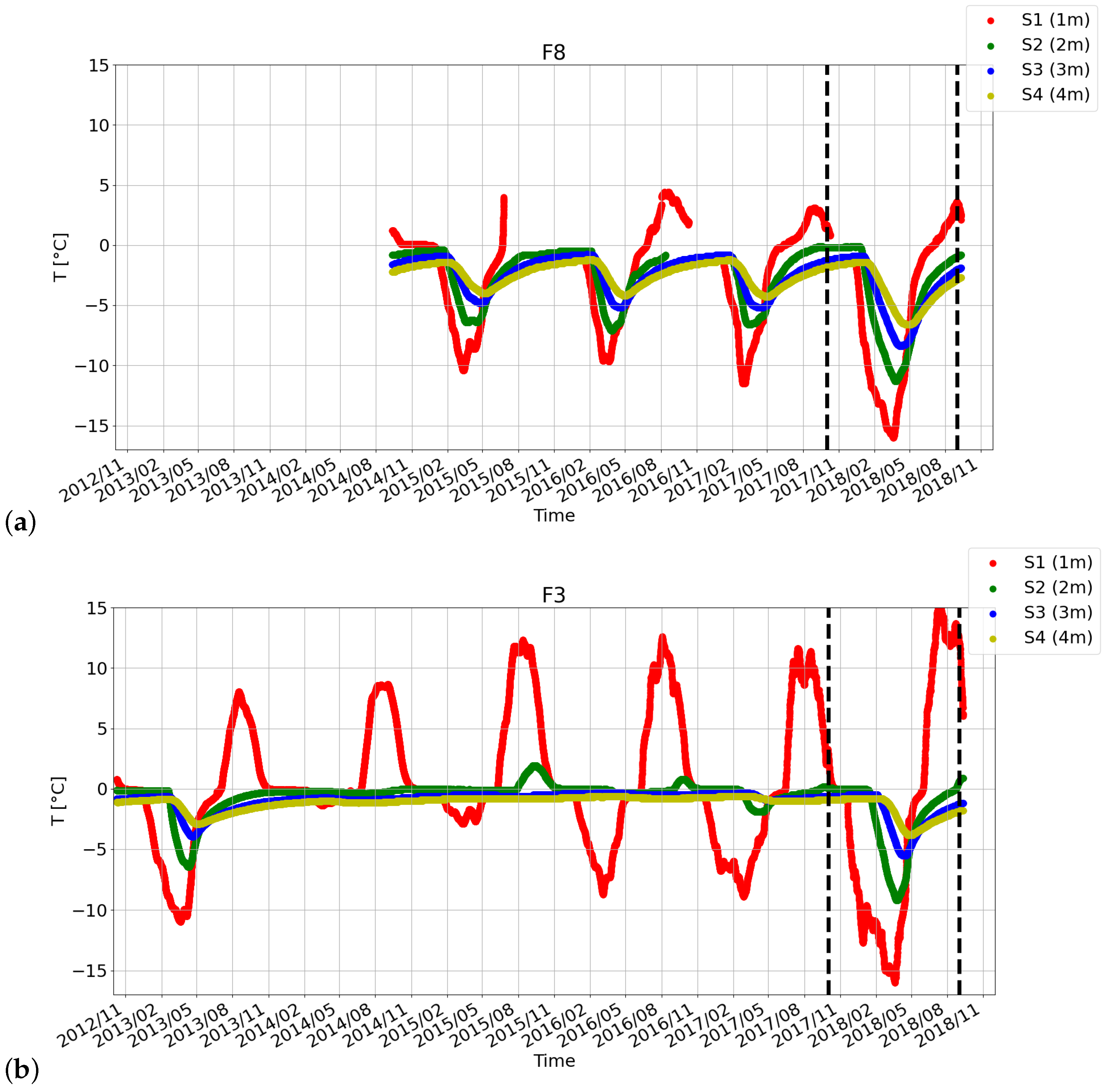
Since September 2012, ground temperature data have been recorded on CS1 transect using HOBO 4-channel data loggers (i.e., model U12-008, with an accuracy of ±0.25 °C [60]). The data loggers were installed inside manually-drilled boreholes placed in the river (F13 and F14) and on both banks of the river (F4, F3, F8, and F7 in Figure 3a). This provides a means to study the thermal influence of the river and to facilitate access and comparison between opposite riversides. F4, F7, and F8 are outside the river inundation area below meadow coverl while the proximity of the floodplains to the river suggests that F3, F13, and F14 are hydraulically influenced by the river. These sensors cover different thermal regimes and we considered four zones linked with different boundary conditions: (i) the “river zone” with river sediment temperatures, (ii) the “sunny zone” with south-oriented slope temperatures, (iii) an intermediate “mixed zone” around the river, and (iv) the “shaded zone” with north-oriented slope temperatures. Each borehole features four monitoring depths: for F3, F4, F7, and F8 at 1 m, 2 m, 3 m, and 4 m, and for F13 and F14 at 0.3 m, 1.2 m, 2, and 3 m. These depths were chosen because of easiness of digging, especially in the river area. Temperature and water content time series are from August 2014 to October 2018 (August 2012 to December 2018, respectively) and were acquired in the F8 (resp. F3) borehole presented in Figure 4. In F8, which is located about ten meters away from the south river bank, temperatures deeper than 2 m are always below 0 °C. The sensor at 1 m depth in F8 indicates thawing conditions start around mid-June every year, and warming usually starts just before April (see Figure 4a). In borehole F3, which is located in the riverbed, the temperature is almost constant all year round at 3 and 4 m depth, except in winter 2012 and 2018, which illustrate the river effect on the thermal state just below. The sensor at 2 m depth has consistently showed positive temperatures at the end of summer since October 2014. In both locations, F3 and F8, winter 2018 is clearly colder than winter 2017, whereas summer 2018 is warmer than summer 2017.
In addition to the borehole temperature, a total of ten Progress-Plus Thermo-Buttons (TB) iBTag (model 22L, with an accuracy of ±0.5 °C) were installed at various locations to automatically record temperatures. The use of such low cost devices allows for a good spatial coverage of conditions in the study area, despite the instruments’ low accuracy. These sensors were previously used for understanding the thermal regime of frozen islands along the Lena floodplain [27]. The adopted strategy relies on monitoring the air, and the surface temperature under various land covers to study land cover types influence the propagation of heat (e.g., to identify the impact of vegetation cover, soil properties, slope and orientation, etc.).
In addition to the temperatures, up to September 2018, transect CS1 was equipped with eleven piezometer tubes for direct ALD measurements during field missions that took place in September. In order to validate these measurements, four trenches were opened 10 m to the west of the CS1 transect on both sides and at different distances from the river. In these trenches, direct temperature, thermal properties (using a Tempos thermal properties analyzer-TTPA-METER group Inc., Pullman, WA, USA), and water content measurements gave us the assurance that the thawed layer thicknesses could be well-estimated from measurements in the piezometer tubes from direct ALD probe soundings or engine auger boreholes. Core samples from the frozen layer exhibited a water content saturation higher than 50%, the associated high ice content made the drill penetration and drill core excavation very difficult due the hardness of the permafrost. When using the drilling equipment, the frozen table depth corresponds to the place where the drill was stopped by the hard, frozen soil. The topography along the two transects CS1 and CS2 was estimated in the field using a theodolite and a few points referenced with a Differential Global Positioning System (DGPS).

3.2. UAV Imagery Acquisitions and Reconstructions

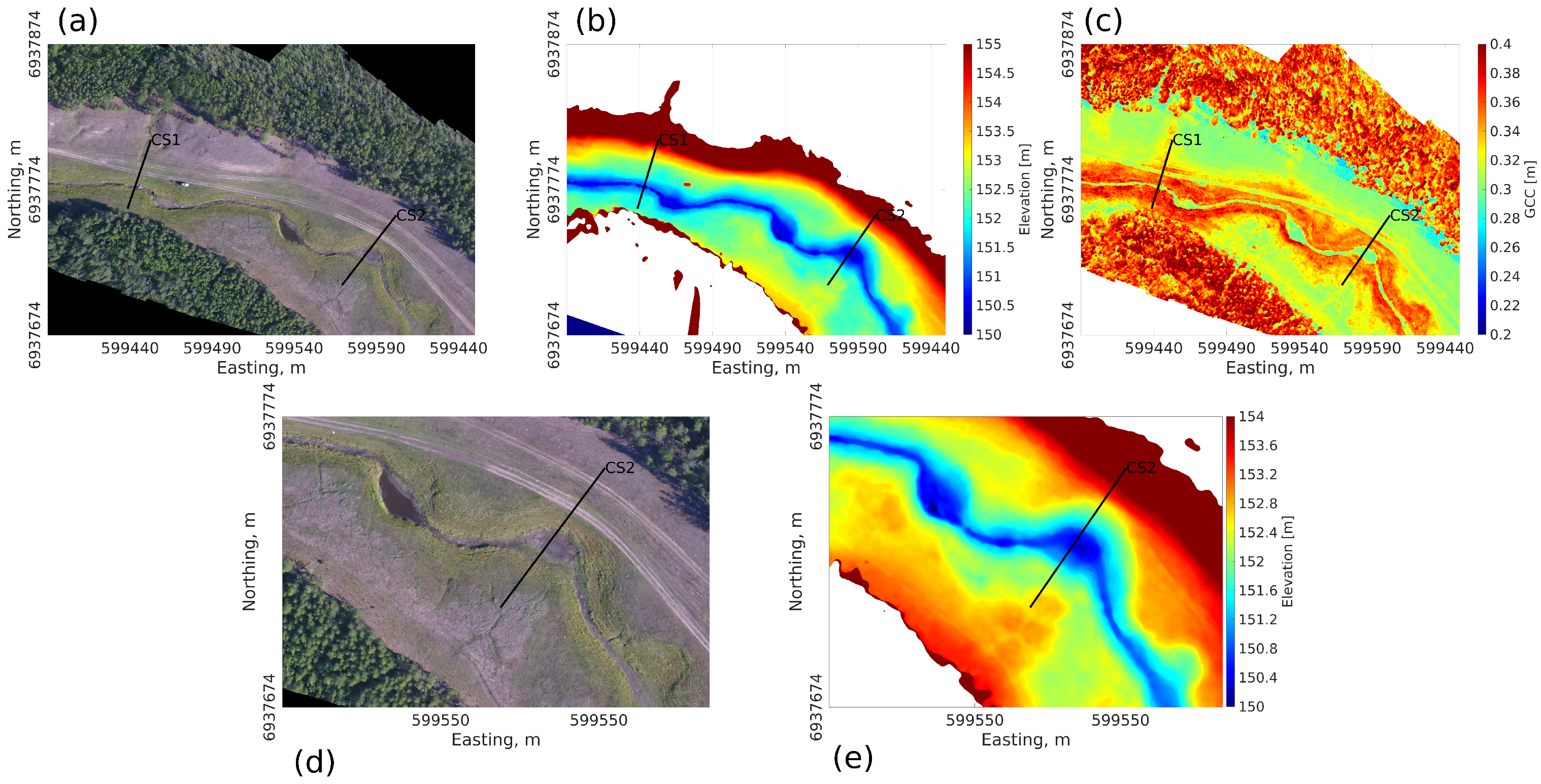
The Uncrewed Aerial Vehicle (UAV) imagery was obtained from a 4-rotor “DJI Phantom 4” (DJI). To cover the full area of interest, three flights were necessary. Visible spectrum (red, green, blue-RGB) imagery was collected with the embedded camera (24.3 megapixels). The angular field of view was 55.8° horizontal vertical, resulting in a 0.009-m ground sampling distance (GSD) at 50 m above ground level. We pre-planned flight lines and shutter intervals to provide 80% overlap. The images were in-flight geo-tagged and time-tagged using the DGPS embedded in the UAV. RGB images collected were processed with pix4D (https://www.pix4d.com/, accessed on 1 January 2023), using a Structure From Motion (SFM) technique to reconstruct the scene based on a large number of overlapping photos. The flowchart was standard, and can be found in many different publications, such as Chen et al. [61] or Gindraux et al. [62], while applied processes on the reconstructed mosaic can be found in, e.g., Dafflon et al. [63]. The Orthomosaic and Digital Surface Model (DSM) was extracted from the point cloud and is presented in Figure 2a,b, respectively. The resolution of the orthomosaic and the DSM were the same, with a spatial resolution of the resulting raster of 0.08 m by 0.08 m in the horizontal dimension and 0.1 m precision in the vertical dimension. The poor satellite coverage, inherent to measurements in secluded areas, explains the difficulty of obtaining a good resolution in elevation. The slope and its orientation were derived from the DSM using an opensource python library [64]. The Green Chromatic Coordinate (GCC) map was derived from the orthomosaic by dividing the Green channel by the sum of all three color channels (Red, Green, and Blue) [65]. As a result, they range between 0 and 1. As the GCC index is known to be a proxy for plant vigor (e.g., ref. [66]), we will indistinctly mention plant vigor or GCC when commenting GCC data. Topography, orientation, and GCC profiles for each transect were made by averaging the data over a one-meter diameter circle (corresponding to π m2 area) on the surface, and the standard deviation was extracted out of this surface.

3.3. Heat Transfer Numerical Experiments

The thermal system evolution was simulated using the Cast3M code (http://www-cast3m.cea.fr/, accessed on 1 January 2023) [39], representing heat transfers with prescribed soil water content properties only. The geometry of the modeled system was a 2D transect centered on the river, extending up to 8 m depth. The length of the transects was set to 44 m for CS1 and 80 m for CS2, respectively (Figure 3). Soil water content distribution and thermal parameters were measured at different depths in pits dug in the active layer near CS1 using the TTPA. For the thermal modeling, an average value was set for the whole model on both transects. The imposed boundary conditions were a geothermal flux at the bottom, zero heat flux on the sidesm and imposed temperature on the top of the modeled transect. These surface conditions result from air temperature measurements at the nearest meteorological station (Yakutsk City). An average year over the whole Syrdakh field monitoring period (2012–2019) was computed and, using the soil temperature just below the surface (10 cm), a transfer function was empirically created. The four different zones (river, shaded, mixed, and sunny zones) provide spatially variable temperature boundary conditions at the top of the modeled transect (Figure 3c). A spin up on this average year was computed until convergence to steady state conditions was achieved. On transect CS1, some minor calibration was made to match temperature time series recorded at different distances from the river during the 2012–2019 period. This calibrated average year provided the time evolution of the whole simulated 2D from which conditions during mid-September field surveys were selected.
In contrast to CS1, no direct thermal ground monitoring had been conducted on the CS2 transect. As a consequence, we used the available CS1 database for the thermal forcing and field investigations, including the actual CS2 topography and river width to delimit the four zones, using the same procedure that was used for CS1. The same approach, in terms of spin up using the average annual temperature time series, was carried out for both transects.

3.4. Ground-Penetrating Radar

Two Ground-Penetrating Radar (GPR) prospecting campaigns were performed in October 2017 and October 2018 when the upper thawed layer depths were close to their annual maxima, right before the start of the freezing period (Figure 4). GPR data were acquired in time domain using the Russian OKO system composed by one set of antennas centered on 150 MHz. In October 2017, the river had mostly dried out at its narrower part, allowing us to use the GPR with facilitated access to the riverbed in the cross-section CS1. However, for CS2, the data were acquired on each side of the water pond (about 50 cm at its deepest part). For all GPR data spatial sampling interval was set to 0.02 m, time sampling was 0.39 ns, and the time window was adjusted to 100 ns. Diffraction hyperbola analysis on CS1 and CS2 transects data gave an estimated electromagnetic wave velocity of 0.05 m/ns and 0.07 m/ns, respectively. On each transect, Stolt migration [67] was performed considering these velocities, which implies some uncertainty on reflector depth estimations where the active layer lithology could be different, for instance, close to the forest at the south end or on the northern part of the profile. Prior to migration, time-zero was set at the first trough and a background removal was applied, as well as a static correction using topography data acquired along the profile with a theodolite. Two-way travel times associated with radar reflections were identified in the radargram using a semi-automatic phase-continuity tool [68].

3.5. Electrical Resistivity Tomography

Electrical Resistivity Tomography (ERT) data were acquired using a 16-channel SibER-64 system with 64 electrodes and a 0.5 m spacing between electrodes, using Dipole-Dipole, Schlumberger, and Wenner configurations. Using a roll-over procedure, we were able to obtain a 63.5 m and a 71.5 m long transect for CS1 and CS2, respectively. The transect for CS2 was collected in 2018 and for CS1 in 2017 and 2018. We left positioning line rods in the field in 2017 to be in the same position for the 2018 survey. Data processing was performed prior to the inversion, consisting mainly of removing extreme contact resistance values due to bad contact with the ground. Data were inverted using the finite-element inversion program BERT [69,70] to obtain the spatial distribution of soil electrical resistivity, including topography. We used a robust inversion (L1-normalization), giving a higher probability to obtain blocky models with sharp boundaries. The triangular mesh was generated using gmsh [71], with 20 surface nodes between each electrodes. This resulted in about 40,000 triangular cells that were associated with an electrical resistivity value. From these electrical resistivity transects, profiles of electrical resistivity variations with depth were generated. This was achieved by extracting the electrical resistivity associated with cells with depths. The electrical resistivity associated with the position of a thermal sensor at a certain depth was computed using the average value over a 0.5-m diameter circle centered on the thermal sensor position and where the standard deviation was derived from the data set on these areas. For all the inverted resistivity models for CS1 and CS2 in any year, the comparison between modeled and measured data showed a root mean squared difference lower than or equal to 4%.

4. Results

4.1. Topographic and Surface Information

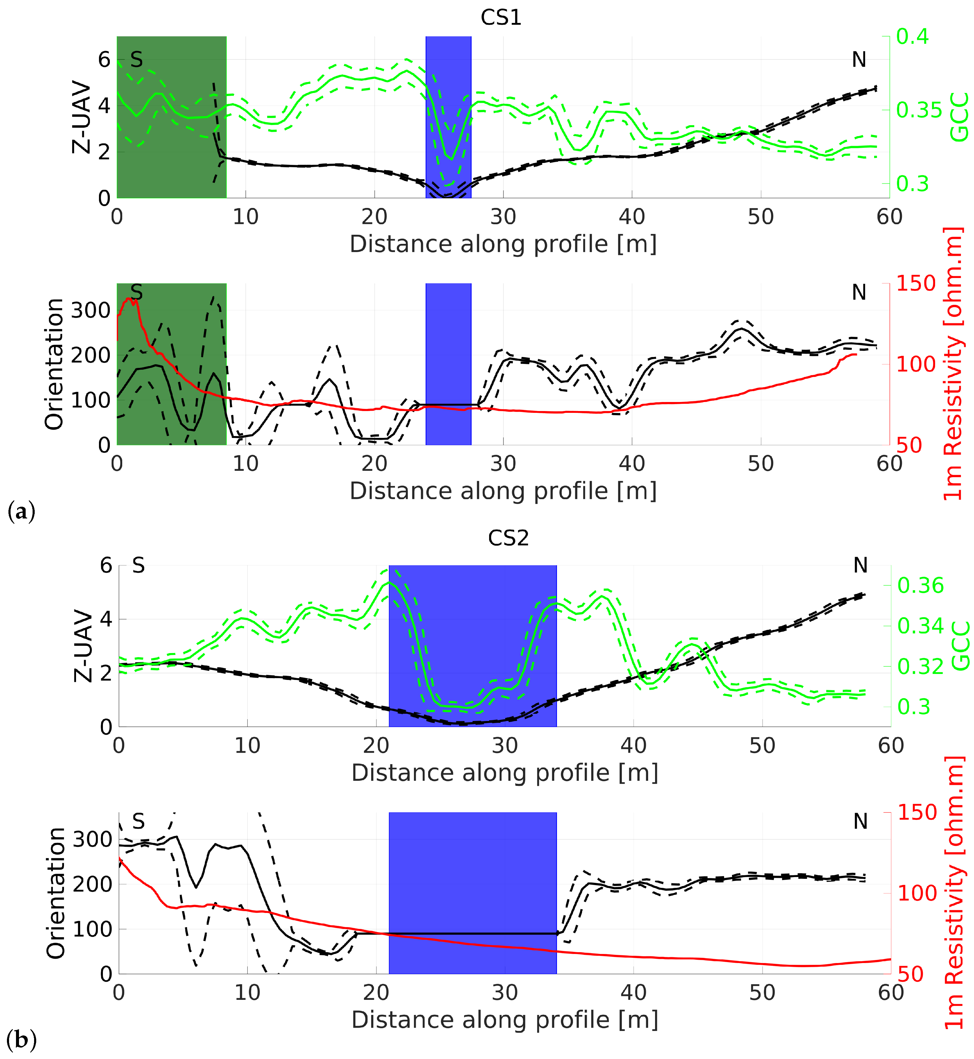
Using the orthomosaic, DSM, and inverted electrical resistivity model, the GCC, topography, orientation, and averaged electrical resistivity over the first 1 m soil depth along CS1 and CS2 transects were derived. Figure 5 presents both transects; plain lines represent the GCC (in green), elevation (Z-UAV), orientation, and resistivity averages (in red) over a one-meter diameter circle (corresponding to π m2) on the surface, while the dashed lines are the standard deviation (see Section 3.2 and Section 3.5). The forest area in the south is indicated by the green boxes; remote sensing indexes in this area might be affected by branches, leaves, and shadows. The river corresponds to the topographic low situated between 24–27.5 m for CS1 (Figure 5a) and 21–33 m for CS2 (Figure 5b). The river zones are represented by the blue boxes.
Overall, CS1 exhibits contrasts between the southern and the northern side of the river (Figure 5a). The topography and the orientation is more pronounced on the northern side (oriented SW ≈ 200°), and average electrical resistivity of the first meter of the northern side reaches up to 100 Ohm.m while the southern side stays at 75 ohm.m outside the forest, indicating less water content (assuming constant mineralisation) on the northern part, which was corroborated with weaker plant vigor (GCC). In the forested part UAV-derived data are erroneous, but the electrical resistivity shows consistently high values, reaching 150 Ohm.m, likely due to the presence of roots, rocks, and voids. Transect CS2 (Figure 5b) shows the same difference in topography and orientation between the left (south) and the right (north) banks of the river as CS1. The GCC index decreases slightly more in the northern side than in the southern side, corresponding to the spatial variability of average electrical resistivity of the first meter. The vegetation seems more vivid in the vicinity of the river, with maximum GCC index values found closest to the river banks. This is more pronounced for CS2, where the river is wider than for CS1. For both transects, the GCC decreases continuously towards the forested areas on either side of the river channel. In addition, the northern bank (south oriented ≈ 200) exhibits a lower GCC value than the southern side. For both transects, a contrast between both riversides is visible in terms of water content deduced from GCC and surface electrical resistivity.

4.2. Numerical Thermal Modeling

Six different isotherms were plotted for each transect in Figure 6, resulting from the thermal modeling presented in Section 3.3. The isotherms represent the model state at the end of the thawing period (September 15 of the average year). We chose these six isotherms, ranging from 0 °C to −0.5 °C, to illustrate the sensitivity of the depth variations depending on how we define the active layer/permafrost transition. The thermal impact of the river width and the differences in surface zonations result in a clear difference in the depth of different isotherms between the two transects, as shown in Figure 6. Beyond the clear impact of the river on the thermal regime, one has to note that the right bank exhibits a 30 cm deeper 0 °C isotherm than the left bank for both transects. However, they differ from each other in term of ALD, which keeps increasing with distance for CS1, while this is not the case for CS2. The active layer on the north bank seems more affected for CS1 than CS2. For both transects the river-affected zone is bulb-shaped. It seems that the bulb symmetry present under the river for CS2 is more symmetric than CS1, where its southern side is shallower than its northern side. This (a)symmetrical shape corresponds to the soil moisture variations (see the resistivity red curve in Figure 5) where the south-oriented side is drier. In addition, a small anomaly at 10 m from the beginning of the profile in CS1 in the −0.5 °C isotherm is noticeable, showing a lateral decrease in temperature on this zone linked to a potential thermal anomaly. The distances between the various isotherms are in the range of 10 to 20 cm far from the river but are large below the river (more than 50 cm due to the smooth vertical temperature gradients), showing the sensibility of the system to a few tens of degrees warmer or colder temperatures in the river area.

4.3. GPR Field Data on CS1 Transect

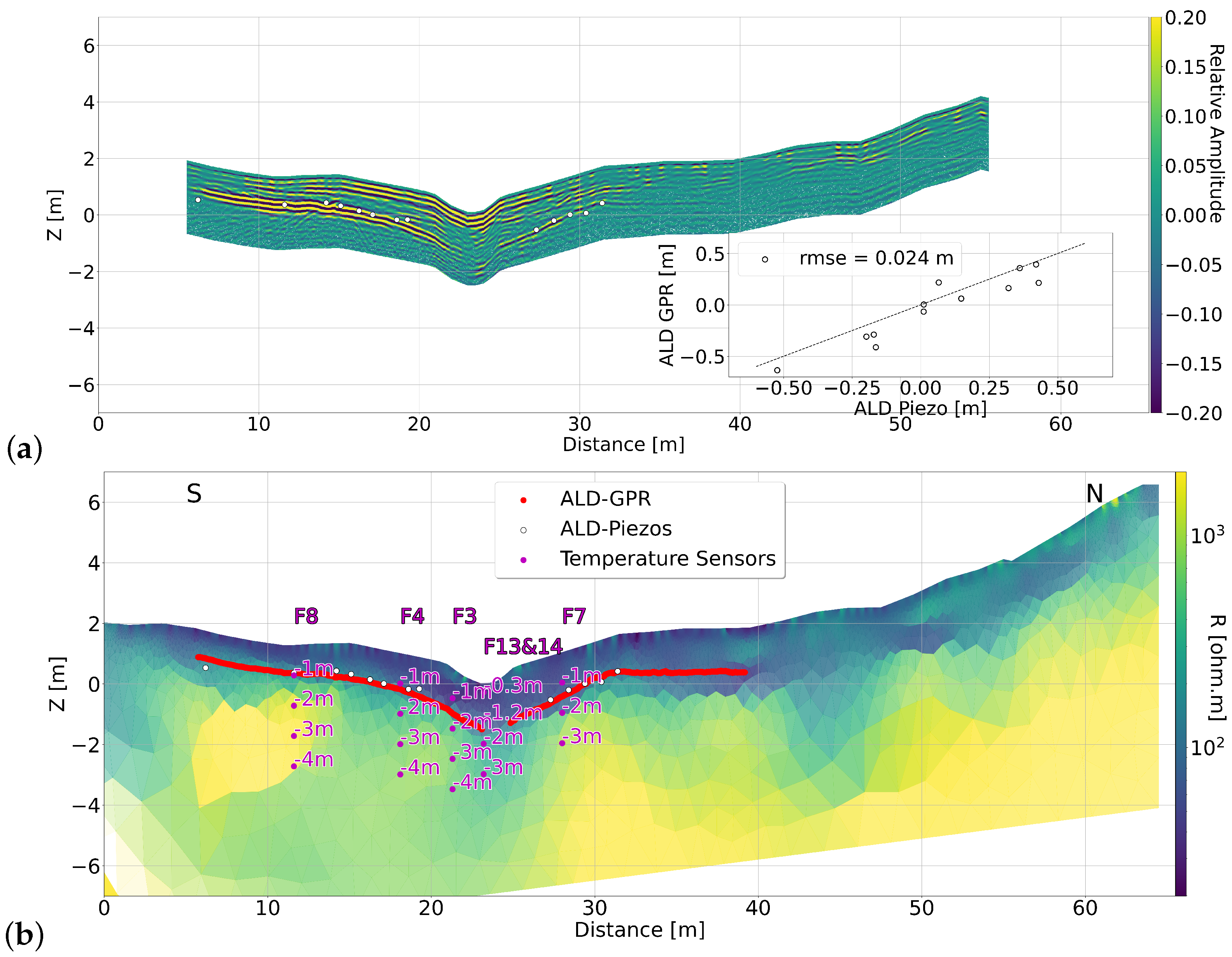
The migrated radargram on transect CS1 acquired during September 2017 is presented in Figure 7a. A strong reflection is visible, extending from 5 to 23 m along the track, disappearing under the river and re-appearing with a lighter amplitude on the northern bank until 38 m along-track. Using the seasonally thawed layer thickness measurements dispatched on the transect (white circles), we saw visual correspondences between the permafrost ceiling and this reflection for most of the piezometer points. The inset in Figure 7a, cross-comparing AL depth retrieved with GPR picking vs AL depth obtained from the piezometers shows a fair RMSE value of 0.024 m. The absence of a strong reflector on the south-facing side in the radargram is either a proof of the continuity of the permafrost on the first 6 m or a signal that is highly attenuated by AL heterogeneity dispersion or a thicker AL. A trench opened on the north side of transect CS1 in this zone showed an AL thickness of 2.2 m. This determination was difficult due to an extremely low ice content in the lower soil layers that allowed digging to some extent. Soil property and temperature measurements unequivocally indicated the frozen state of the soil.

4.4. Electrical Resistivity Tomography

4.4.1. Transect CS1

The electrical resistivity profile obtained from CS1 in 2017 from ERT data inversion is presented in Figure 7b. For visual comparison, positions of temperature sensors (in purple circles), thawed layer thicknesses obtained for direct measurements (in white circles), and GPR reflection from radargram Figure 7a (red line) were plotted along with the electrical resistivity profile. The resistivity values span from 101 to 104 Ohm.m, as logarithmically displayed here. Overall, the resistivity profile seems to be split in two parts, with the river as a boundary; the northern part exhibits larger resistivity values compared to the southern part. Vertically, the distribution appears to be different for both parts. The northern part first exhibits a moderately resistive layer of about 1–2 m thickness over a largely resistive layer, reaching 6 m in depth. The southern part of the resistivity profile exhibits a more conductive zone of approximately 1–2 m thickness, visually above the GPR reflector, over a deeper resistant zone. The southern part, at about 10 m from the beginning of the transect line, exhibits a more resistive anomaly, is very well defined, and is surrounded by less resistive media.
Below the river, a more conductive, bulb-shaped zone is strongly present until about 1 m depth and is less defined from 3 to 6 m depth. In agreement with the literature (e.g., ref. [43]), our GPR reflector, and our point measurements (temperature and drilling), we identified the top conductive layer as the thawed layer, while the more resistive area likely corresponds to the permafrost. The resistive anomaly at 10 m could be interpreted as an ice wedge, which are frequently found in soil cores in the area [72]. While not proven with an ice core taken by ourselves, this is coherent with the colder temperature measured in borehole F8 compared to borehole F3 (Figure 4).

4.4.2. Transect CS2

The electrical resistivity profile obtained from the 2018 ERT data inversion is presented in Figure 8 for the CS2 transect. The ALD retrieved from GPR is presented as a red line in the same way as CS1. Similar to the CS1 transect, the electrical resistivity distribution is different between the north and south sides of the river. However, as opposed to CS1, the larger resistive anomaly is on the southern side. The conductive shallow layer, in agreement with the GPR main reflector position, is thicker (around 4 m thick) and more conductive on the northern side, while on the southern side the first layer is about one meter thick. The conductive, bulb-shaped anomaly surrounding the river is about 10 m wide and much deeper and larger than the one observed for the CS1 transect. About 60 m along the track, another large conductive anomaly was visible at about 3–4 m deep and 10 m wide, with values in the same order of magnitude as under the river.

4.5. GPR and Electrical Resistivity Vertical Profile Variations

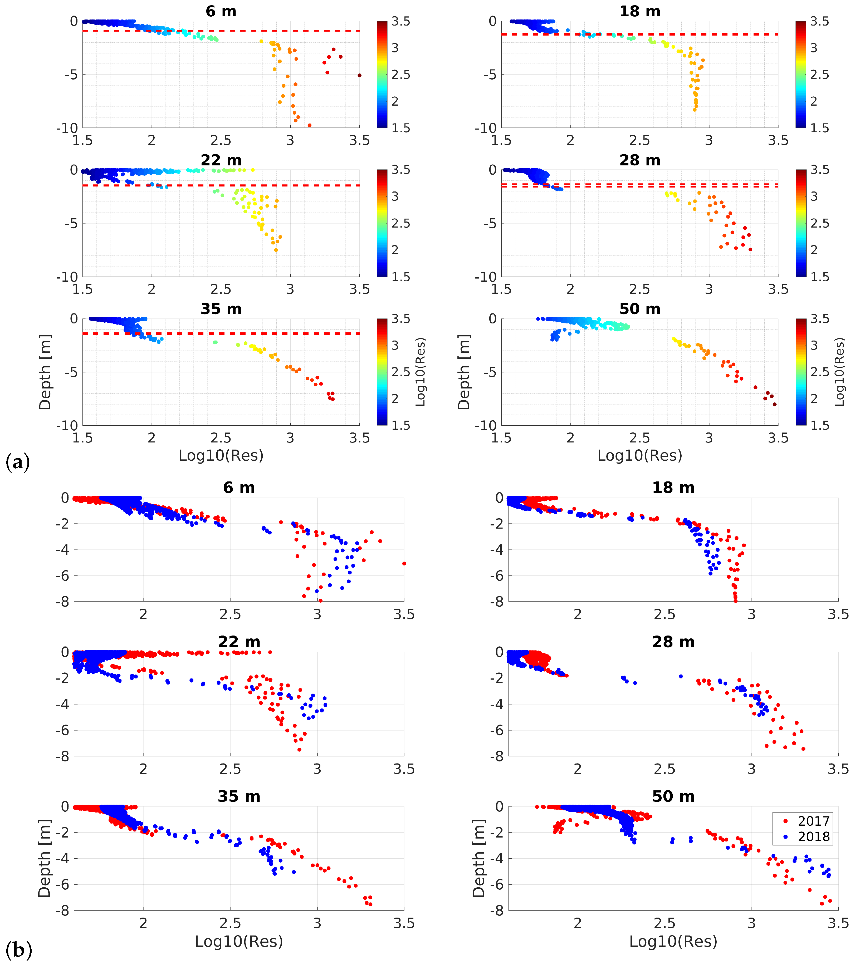
The electrical resistivity values at various depths at selected positions along the CS1 profile are displayed in Figure 9a. In each sub-figure the position of the GPR reflector, attributed to the permafrost table, is represented by red dashed lines when available (compared with Figure 7). The vertical electrical resistivity depth profiles show different behavior and variations depending on their sides and proximity of and to the river. It is noticeable that for all of them except the 50-m along-track profile, the electrical resistivity in the vicinity of the permafrost table changes sharply from about 80 Ohm.m to 1000 Ohm.m and this transition, precisely the 320 Ohm.m threshold, visually corresponds to the GPR reflector position when visible.
The profile in the riverbed (22 m along-track) reaches high resistive values at the very surface before transitioning to low values of 80 Ohm.m linked to the active layer. At 50 m along-track, within the first 3 m in depth, the rise of the electrical resistivity to about 102.5 Ohm.m, followed by a decrease down to 80 Ohm.m before increasing again deeper (in permafrost), is probably responsible for the disappearance of the GPR reflection on the AL base (see Figure 7a). These abrupt contrasts in electrical resistivity are likely responsible for the light GPR reflection we observe at 0.8 m deep on the radargram of Figure 7 between 45 and 53 m along-track. Here, this layer is “masking” the active layer bottom reflection.
Using the same depth-profile representation, we compared resistivity profiles in Figure 9b for the years 2017 in red and 2018 in blue. The distributions are very similar for positions not in the vicinity of the river (e.g., profiles at 28, 35, and 50 m along-track), even when, for the 50 m profile, the drop in resistivity at about 1 m was not present in 2018. This might be related to differences in surface wetness or fluid conductivity due to recent rain events. There are more pronounced differences in the near-surface for distributions at position 18 and 22 m, most likely due to a change in surface water content that is mainly linked to different river water levels. According to these depth-profile graphics, the differences between the two years of observations of the ALD, corresponding to the abrupt resistivity changes, are less than 0.1 m. Below 4 m depth we observe slight differences in resistivity that are difficult to interpret and are probably inherent to the inversion scheme and positioning uncertainties.

4.6. Relationship between Electrical Resistivity and Temperature

Using inverted ERT from the two years of field campaigns and temperatures from on-site monitoring soil sensors, we compared the relationship between inverted electrical resistivity and monitoring temperature in Figure 10, depending on the year of measurements (2017 or 2018). The global trend of the obtained relationship is following a linear decrease with increasing temperature above the freezing point, according to Archie [73]’s law. For temperatures below the freezing point, the resistivity follows an exponential increase [74,75]. We illustrated the freezing temperature by the zero-isotherm line, but we are aware that the freezing can happen for colder temperatures (approximately −1 °C), due to mineralization in water, implying a change in fluid electrical conductivity, and this is likely what we have observed here. We recall that the temperature error bars are associated with manufacturer specification (±0.25 °C) and resistivity error bars associated with the spatial variability on a 0.5 m circle centered on the thermal sensor positions. In general, the resistivity between the two survey years is not drastically different, as most of the resistivity values in the same spot are within the error bar intervals of each year. An exception to this is the sensors in the riverbed (F13 and F14), where the river temperature was higher in 2018 and likely impacted the measurements below. However, minor differences exist. The most noticeable is the higher surface temperature (for measurements around 1 m) in 2018 compared to 2017, which is associated with more precipitation in 2018. For lower temperatures, below 0 °C and lower, it seems to be the opposite behavior, i.e,. at roughly the same resistivity, temperatures were colder in 2018 compared to 2017. The range spanned by resistivity values increased near the 0 °C boundary (roughly between −1 °C and +1 °C) as expected, since this temperature range corresponds to the most affected area undergoing the freeze–thaw processes (Figure 9; frozen/partially frozen/unfrozen).

5. Discussion

The dataset presented in this study is a unique set of field observations in Yakutia. In the following, we focus on three main discussion points concerning the geophysical interpretation, the modeling extrapolation, and how both approaches can be merged.

5.1. Geophysical Derived Information

Resistivity profile comparisons between 2017 and 2018 at the CS1 transect (Figure 9b) exhibit strong similarities, except in the first meter, where the 2017 measurements gave a higher electrical resistivity than 2018. This is coherent with surface water content conditions observed within these two years, where 2017 was much drier than 2018. These differences in surface resistivity can lead to a resistivity model that is slightly different at a larger depth, numerically equivalent to the one with the best data fitting [76]. Even with these differences, which are mainly visible deeper than 2 m, the yearly comparison executed with setting new electrodes in the ground does not lead to major discrepancies, demonstrating the robustness of the approach for monitoring permafrost thermal degradation over different years in remote areas without the possibility to leave monitoring systems in place (see, for instance, Uhlemann et al. [40]).
Beyond the multi-year geophysical survey, the geophysical information showed that the wider the river is, the deeper its thermal influence on permafrost, as expected. This is very well-illustrated in our comparison of the two transects, with CS2 being located at a pond meander, making it more thermally affected than CS1. The UAV-derived products are in support of these findings, especially the DSM (see the zooms in Figure 2d,e), corroborating the likely existence of ice wedges on the south-western part of CS2, visible by the topographic anomaly. All this information (width/depth of river influence and UAV-derived) could be used to estimate the river thermal influence on permafrost and the degradation state in this valley.

5.2. Thermal Modeling versus Geophysical Information

As presented in Figure 3, the modeling approach takes advantage of a large volume of observations available at CS1: a zonation of surface boundary conditions derived from thermal monitoring at various positions and depths. Confronting geophysical results (Figure 7) with numerical simulations for the same date (Figure 6) shows a general agreement when it comes to the structure of the active layer across the river, deeper in the sun oriented slope (right bank) as compared with the left bank in shaded conditions. The river thermal influence in the middle of the valley is coherently deeper when the river is larger. The deeper isotherms on the south-facing bank compared to the ones on north-facing bank were qualitatively confirmed by GPR and ERT data on both transects (Figure 8).
The numerical simulation has not implemented heterogeneous soil thermal properties. However, the resistive anomaly centered at about 9 m along-track of CS1 in the ERT profile (visible in Figure 7b) corresponds to local variations in isotherms as they appeared in Figure 6a at the same distance. Interpreted as an ice wedge in formation, it is a strong argument in favor of coupling thermal numerical modeling with geophysically-derived information. Despite the fact that it is well beyond the capabilities of the actual simulation approach, this study tends to go toward the addition of geophysical data for spatially filling and refining the thermal properties between zonations (made from long term monitoring in situ data), with the aim of refining the numerical simulation.

5.3. Extending CS1 Interpretation Framework to Valley Characterization

The dense thermal monitoring instrumentation at the reference transect CS1, as well as complementary soil characterization and geophysical campaigns, provide a unique set of field conditions to test and evaluate the quality of thermal modeling approaches. When a good level of realism and confidence are obtained, these modeling approaches will then serve to study the evolution of permafrost along the river courses and predict the changes in the hydrological conditions within the water catchment or within a larger region. Comparing only the geophysically monitored transect CS2 (Figure 8) with the numerical modeling in Figure 6, we clearly observed that the numerical thermal modeling differs from the geophysical information. This is especially obvious when comparing the conductive part of the CS2 transect on the N bank of the river, which is unfrozen if we refer to Figure 10 but does not appear unfrozen on the thermal modeling. Several reasons can lead to differences between numerical thermal modeling and geophysical data. Insufficient spatial resolution and homogeneous soil parameterization cannot account for small scale heterogeneity in the sub-surface, including varying ice and soil water contents. However, heterogeneity of the frozen media was observed to be an important factor for thermal ground evolution, for instance, in laboratory experiments and field observations in the case of retrogressive thaw slumps [77]. One of the potential solutions in cases like ours would be iterative thermal model parameter calibration on obtained geophysical responses on well-constrained transect (CS1 for instance); obtained parameter sets could be applied to less-constrained sites. The available UAV dataset, showing the beginning of ice-wedge formation close to CS2, provides additional information for validation and a priori classification of a study area’s thermal regime to constrain boundary conditions for modeling and geophysical prospecting. For Syrdakh, a fully comprehensive approach is still in development due to delays caused by international conflicts.
The river is in an alas valley that was likely formed in the early Holocene period by the thawing of the upper part of the ice-rich permafrost [51]. In the future, following the enhanced warming of air temperature, it is possible that the deepening of the active layer may reach deeper ice-rich sediments and develop thermokarst processes. Whether the Central Yakutian climate will become drier or wetter is debated, thus impacting the water and the thermal regime of the river. Either of these hypotheses will have a strong impact on water resources for the future, especially for the Yakutian communities.

6. Conclusions

In this paper we have presented a unique dataset along two transects in a remote fluvial valley in Yakutia, aiming to quantify permafrost/active layer thermal regimes linked with the river. One of the transects, CS1, has been highly instrumental in monitoring thermal evolution and variations in soil water content since 2012m whereas the other one, CS2, was left pristine. The study showed that point scale measurements, GPRm and ERT data are all in agreement with each other to determine the ALD at locations where it can be estimated by direct measurements. As these direct measurements are, by definition, limited in space, our study suggests that applying GPR and ERT on densely instrumented transects allows us to sustain the continuity of time and space information for frozen/unfrozen media evolution. The thermal modelings presented in these study, only taking into account long-term temperature time series, give consistent results with geophysical measurements (GPR and ERT) and can be thought of as a first step that paves the way to coupled inversion for space and time evolution. The temperature-resistivity relationships covering a two-year time-lapse exhibit some differences, illustrating the role of water in the context of river–permafrost influence. This is corroborated with the UAV imaging upscaling the point-scale and geophysical data through micro-topography and vegetation indices, exhibiting degradation zones illustrated in ice-wedge polygons.

Author Contributions

Conceptualization, A.S. (Albane Saintenoy) and C.G.; methodology, E.L., A.S. (Albane Saintenoy) and C.G.; software, E.L., A.S. (Albane Saintenoy), C.G. and C.M.; validation, A.S. (Albane Saintenoy), C.G. and E.L.; formal analysis, E.L., A.S. (Albane Saintenoy) and C.G.; field investigation, A.S. (Albane Saintenoy), C.G., E.P., F.B., K.D., K.B., M.P., A.S. (Antoine Séjourné), I.K., A.F. and P.K.; resources, A.S. (Albane Saintenoy), C.G. and A.S. (Antoine Séjourné); data curation, E.L., A.S. (Albane Saintenoy), E.P. and C.G.; writing–original draft preparation, E.L., C.G., A.S. (Albane Saintenoy), E.P., F.B. and C.M.; writing–review and editing, E.L., A.S. (Albane Saintenoy), E.P., A.S. (Antoine Séjourné), F.B., C.M. and F.C.; visualization, E.L. and A.S. (Albane Saintenoy); supervision, C.G. and A.S. (Albane Saintenoy); project administration, C.G. and P.K.; funding acquisition, C.G., A.S. (Albane Saintenoy), E.P. and A.S. (Antoine Séjourné). All authors have read and agreed to the published version of the manuscript.

Funding

This research received different funding from Institut Pierre-Simon Laplace (A0 Recherche 2018), Universite Paris Saclay (AO Emergence SPU Paris-Saclay 2019) and the French Research Agency ANR (HiperBorea project, grant number ANR-19 CE46-0003-01).

Data Availability Statement

Dataset are available on demand from the corresponding author and on 10.5281/zenodo.7885821.

Acknowledgments

This study is dedicated to Christophe Grenier, who we all deeply miss. We are deeply grateful to the inhabitants of Syrdakh village. The authors thank three anonymous reviewers for their work which improved the quality of the manuscript.

Conflicts of Interest

The authors declare no conflict of interest.

References

  1. Working Group I. Climate Change: The IPCC Scientific Assessment; Houghton, J.T., Jenkins, G., Ephraums, J.J., Eds.; Cambridge University Press: Cambridge, UK, 1990; Volume 1, p. 990. [Google Scholar]
  2. Overland, J.; Dunlea, E.; Box, J.E.; Corell, R.; Forsius, M.; Kattsov, V.; Olsen, M.S.; Pawlak, J.; Reiersen, L.O.; Wang, M. The urgency of Arctic change. Polar Sci. 2019, 21, 6–13. [Google Scholar] [CrossRef]
  3. Previdi, M.; Smith, K.L.; Polvani, L.M. Arctic amplification of climate change: A review of underlying mechanisms. Environ. Res. Lett. 2021, 16, 093003. [Google Scholar] [CrossRef]
  4. Serreze, M.; Barrett, A.; Stroeve, J.; Kindig, D.; Holland, M. The emergence of surface-based Arctic amplification. Cryosphere 2009, 3, 11–19. [Google Scholar] [CrossRef]
  5. Pörtner, H.O.; Roberts, D.C.; Masson-Delmotte, V.; Zhai, P.; Tignor, M.; Poloczanska, E.; Weyer, N. The ocean and cryosphere in a changing climate. In IPCC Special Report on the Ocean and Cryosphere in a Changing Climate; Intergovernmental Panel on Climate Change: Geneva, Switzerland, 2019. [Google Scholar]
  6. Hjort, J.; Karjalainen, O.; Aalto, J.; Westermann, S.; Romanovsky, V.E.; Nelson, F.E.; Etzelmüller, B.; Luoto, M. Degrading permafrost puts Arctic infrastructure at risk by mid-century. Nat. Commun. 2018, 9, 5147. [Google Scholar] [CrossRef]
  7. Jorgenson, M.T.; Romanovsky, V.; Harden, J.; Shur, Y.; O’Donnell, J.; Schuur, E.A.; Kanevskiy, M.; Marchenko, S. Resilience and vulnerability of permafrost to climate change. Can. J. For. Res. 2010, 40, 1219–1236. [Google Scholar] [CrossRef]
  8. Petrone, K.; Hinzman, L.; Shibata, H.; Jones, J.; Boone, R. The influence of fire and permafrost on sub-arctic stream chemistry during storms. Hydrol. Process. Int. J. 2007, 21, 423–434. [Google Scholar] [CrossRef]
  9. Pithan, F.; Mauritsen, T. Arctic amplification dominated by temperature feedbacks in contemporary climate models. Nat. Geosci. 2014, 7, 181–184. [Google Scholar] [CrossRef]
  10. Throop, J.; Lewkowicz, A.G.; Smith, S.L. Climate and ground temperature relations at sites across the continuous and discontinuous permafrost zones, northern Canada. Can. J. Earth Sci. 2012, 49, 865–876. [Google Scholar] [CrossRef]
  11. Romanovsky, V.; Osterkamp, T. Effects of unfrozen water on heat and mass transport processes in the active layer and permafrost. Permafr. Periglac. Process. 2000, 11, 219–239. [Google Scholar] [CrossRef]
  12. Shiklomanov, N.; Nelson, F.; Streletskiy, D.; Hinkel, K.; Brown, J. The circumpolar active layer monitoring (CALM) program: Data collection, management, and dissemination strategies. In Proceedings of the Ninth International Conference on Permafrost, Fairbanks, AK, USA, 29 June–3 July 2008; Institute of Northern Engineering Fairbanks Alaska: Fairbanks, AK, USA, 2008; Volume 29, pp. 1647–1652. [Google Scholar]
  13. Biskaborn, B.K.; Lanckman, J.P.; Lantuit, H.; Elger, K.; Streletskiy, D.; Cable, W.; Romanovsky, V.E. The new database of the Global Terrestrial Network for Permafrost (GTN-P). Earth Syst. Sci. Data 2015, 7, 245–259. [Google Scholar] [CrossRef]
  14. Riseborough, D. Soil latent heat as a filter of the climate signal in permafrost. In Proceedings of the Fifth Canadian Permafrost Conference, Collection Nordicana, Quebec City, QC, Canada, 5–9 June 1990; Citeseer: Princeton, NJ, USA, 1990; Volume 54, pp. 199–205. [Google Scholar]
  15. Walvoord, M.A.; Kurylyk, B.L. Hydrologic Impacts of Thawing Permafrost–A Review. Vadose Zone J. 2016, 15, 1–20. [Google Scholar] [CrossRef]
  16. Hughes-Allen, L.; Bouchard, F.; Séjourné, A.; Fougeron, G.; Léger, E. Automated Identification of Thermokarst Lakes Using Machine Learning in the Ice-Rich Permafrost Landscape of Central Yakutia (Eastern Siberia). Remote Sens. 2023, 15, 1226. [Google Scholar] [CrossRef]
  17. Mackay, J.; Burn, C. The first 20 years (1978–1979 to 1998–1999) of ice-wedge growth at the Illisarvik experimental drained lake site, western Arctic coast, Canada. Can. J. Earth Sci. 2002, 39, 95–111. [Google Scholar] [CrossRef]
  18. Yoshikawa, K.; Hinzman, L.D. Shrinking thermokarst ponds and groundwater dynamics in discontinuous permafrost near Council, Alaska. Permafr. Periglac. Process. 2003, 14, 151–160. [Google Scholar] [CrossRef]
  19. Jorgenson, M.T.; Shur, Y. Evolution of lakes and basins in northern Alaska and discussion of the thaw lake cycle. J. Geophys. Res. Earth Surf. 2007, 112. [Google Scholar] [CrossRef]
  20. Plug, L.J.; West, J. Thaw lake expansion in a two-dimensional coupled model of heat transfer, thaw subsidence, and mass movement. J. Geophys. Res. Earth Surf. 2009, 114. [Google Scholar] [CrossRef]
  21. Rowland, J.C.; Travis, B.J.; Wilson, C.J. The role of advective heat transport in talik development beneath lakes and ponds in discontinuous permafrost. Geophys. Res. Lett. 2011, 38. [Google Scholar] [CrossRef]
  22. Kurylyk, B.L.; MacQuarrie, K.T.; McKenzie, J.M. Climate change impacts on groundwater and soil temperatures in cold and temperate regions: Implications, mathematical theory, and emerging simulation tools. Earth Sci. Rev. 2014, 138, 313–334. [Google Scholar] [CrossRef]
  23. Johansson, E.; Gustafsson, L.G.; Berglund, S.; Lindborg, T.; Selroos, J.O.; Liljedahl, L.C.; Destouni, G. Data evaluation and numerical modeling of hydrological interactions between active layer, lake and talik in a permafrost catchment, Western Greenland. J. Hydrol. 2015, 527, 688–703. [Google Scholar] [CrossRef]
  24. Lemieux, J.M.; Fortier, R.; Talbot-Poulin, M.C.; Molson, J.; Therrien, R.; Ouellet, M.; Banville, D.; Cochand, M.; Murray, R. Groundwater occurrence in cold environments: Examples from Nunavik, Canada. Hydrogeol. J. 2016, 24, 1497–1513. [Google Scholar] [CrossRef]
  25. Woo, M.k. Permafrost Hydrology; Springer Science & Business Media: Berlin/Heidelberg, Germany, 2012. [Google Scholar]
  26. Costard, F.; Dupeyrat, L.; Gautier, E.; Carey-Gailhardis, E. Fluvial thermal erosion investigations along a rapidly eroding river bank: Application to the Lena River (central Siberia). Earth Surf. Process. Landforms J. Br. Geomorphol. Res. Group 2003, 28, 1349–1359. [Google Scholar] [CrossRef]
  27. Costard, F.; Gautier, E.; Konstantinov, P.; Bouchard, F.; Séjourné, A.; Dupeyrat, L.; Fedorov, A. Thermal regime variability of islands in the Lena River near Yakutsk, eastern Siberia. Permafr. Periglac. Process. 2022, 33, 18–31. [Google Scholar] [CrossRef]
  28. Gautier, E.; Dépret, T.; Costard, F.; Virmoux, C.; Fedorov, A.; Grancher, D.; Konstantinov, P.; Brunstein, D. Going with the flow: Hydrologic response of middle Lena River (Siberia) to the climate variability and change. J. Hydrol. 2018, 557, 475–488. [Google Scholar] [CrossRef]
  29. Schuur, E.A.; McGuire, A.D.; Schädel, C.; Grosse, G.; Harden, J.W.; Hayes, D.J.; Hugelius, G.; Koven, C.D.; Kuhry, P.; Lawrence, D.M.; et al. Climate change and the permafrost carbon feedback. Nature 2015, 520, 171–179. [Google Scholar] [CrossRef]
  30. Vonk, J.E.; Gustafsson, Ö. Permafrost-carbon complexities. Nat. Geosci. 2013, 6, 675–676. [Google Scholar] [CrossRef]
  31. Crampton, C. Changes in permafrost distribution produced by a migrating river meander in the northern Yukon, Canada. Arctic 1979, 32, 148–151. [Google Scholar] [CrossRef]
  32. Arcone, S.A.; Chacho, E.F.; Delaney, A.J. Seasonal structure of taliks beneath arctic streams determined with ground-penetrating radar. In Proceedings of the seventh International Permafrost Conference, Yellowknife, NT, Canada, 23–27 June 1998; International Permafrost Association, Canadian National Committee: Ottawa ON, Canada, 1998; pp. 19–24. [Google Scholar]
  33. Mikhailov, V. Convective heat exchange between rivers and floodplain taliks. In Proceedings of the Ninth International Conference on Permafrost, Institute of Northern Engineering, University of Alaska, Fairbanks, AK, USA, 29 June–3July 2008; pp. 1215–1220. [Google Scholar]
  34. Brosten, T.R.; Bradford, J.H.; McNamara, J.P.; Gooseff, M.N.; Zarnetske, J.P.; Bowden, W.B.; Johnston, M.E. Estimating 3D variation in active-layer thickness beneath arctic streams using ground-penetrating radar. J. Hydrol. 2009, 373, 479–486. [Google Scholar] [CrossRef]
  35. Minsley, B.; Abraham, J.; Smith, B.; Cannia, J.; Voss, C.; Jorgenson, M.; Walvoord, M.; Wylie, B.; Anderson, L.; Ball, L.; et al. Airborne electromagnetic imaging of discontinuous permafrost. Geophys. Res. Lett. 2012, 39. [Google Scholar] [CrossRef]
  36. Liu, W.; Fortier, R.; Molson, J.; Lemieux, J.M. A conceptual model for talik dynamics and icing formation in a river floodplain in the continuous permafrost zone at Salluit, Nunavik (Quebec), Canada. Permafr. Periglac. Process. 2021, 32, 468–483. [Google Scholar] [CrossRef]
  37. Malenfant-Lepage, J.; Doré, G.; Ingeman-Nielsen, T.; Daniel, F. Using resistivity method to characterize water flow patterns in permafrost environment (Ilulissat, Greenland). In Proceedings of the XI. International Conference on Permafrost, Potsdam, Germany, 20–24 June 2016; p. 966. [Google Scholar]
  38. Roux, N.; Costard, F.; Grenier, C. Laboratory and Numerical Simulation of the Evolution of a River’s Talik. Permafr. Periglac. Process. 2017, 28, 460–469. [Google Scholar] [CrossRef]
  39. Grenier, C.; Anbergen, H.; Bense, V.; Chanzy, Q.; Coon, E.; Collier, N.; Costard, F.; Ferry, M.; Frampton, A.; Frederick, J.; et al. Groundwater flow and heat transport for systems undergoing freeze-thaw: Intercomparison of numerical simulators for 2D test cases. Adv. Water Resour. 2018, 114, 196–218. [Google Scholar] [CrossRef]
  40. Uhlemann, S.; Dafflon, B.; Peterson, J.; Ulrich, C.; Shirley, I.; Michail, S.; Hubbard, S. Geophysical Monitoring Shows that Spatial Heterogeneity in Thermohydrological Dynamics Reshapes a Transitional Permafrost System. Geophys. Res. Lett. 2021, 48, e2020GL091149. [Google Scholar] [CrossRef]
  41. Jafarov, E.E.; Harp, D.R.; Coon, E.T.; Dafflon, B.; Tran, A.P.; Atchley, A.L.; Lin, Y.; Wilson, C.J. Estimation of subsurface porosities and thermal conductivities of polygonal tundra by coupled inversion of electrical resistivity, temperature, and moisture content data. Cryosphere 2020, 14, 77–91. [Google Scholar] [CrossRef]
  42. Tran, A.P.; Dafflon, B.; Bisht, G.; Hubbard, S.S. Spatial and temporal variations of thaw layer thickness and its controlling factors identified using time-lapse electrical resistivity tomography and hydro-thermal modeling. J. Hydrol. 2018, 561, 751–763. [Google Scholar] [CrossRef]
  43. Léger, E.; Dafflon, B.; Robert, Y.; Ulrich, C.; Peterson, J.; Biraud, S.; Romanovsky, V.; Hubbard, S. A distributed temperature profiling method for assessing spatial variability of ground temperatures in a discontinuous permafrost region of Alaska. Cryosphere 2019, 13, 2853–2867. [Google Scholar] [CrossRef]
  44. Léger, E.; Saintenoy, A.; Serhir, M.; Costard, F.; Grenier, C. Brief Communication: Monitoring active layer dynamic using a lightweight nimble Ground-Penetrating Radar system. A laboratory analog test case. Cryosphere Discuss. 2022, 17, 1271–1277. [Google Scholar] [CrossRef]
  45. Wielandt, S.; Uhlemann, S.; Fiolleau, S.; Dafflon, B. Low-Power, Flexible Sensor Arrays with Solderless Board-to-Board Connectors for Monitoring Soil Deformation and Temperature. Sensors 2022, 22, 2814. [Google Scholar] [CrossRef]
  46. Dafflon, B.; Wielandt, S.; Lamb, J.; McClure, P.; Shirley, I.; Uhlemann, S.; Wang, C.; Fiolleau, S.; Brunetti, C.; Akins, F.H.; et al. A Distributed Temperature Profiling System for Vertically and Laterally Dense Acquisition of Soil and Snow Temperature. Cryosphere 2022, 16, 719–736. [Google Scholar] [CrossRef]
  47. Majdański, M.; Dobiński, W.; Marciniak, A.; Owoc, B.; Glazer, M.; Osuch, M.; Wawrzyniak, T. Variations of permafrost under freezing and thawing conditions in the coastal catchment Fuglebekken (Hornsund, Spitsbergen, Svalbard). Permafr. Periglac. Process. 2022, 33, 264–276. [Google Scholar] [CrossRef]
  48. McClymont, A.F.; Hayashi, M.; Bentley, L.R.; Christensen, B.S. Geophysical imaging and thermal modeling of subsurface morphology and thaw evolution of discontinuous permafrost. J. Geophys. Res. Earth Surf. 2013, 118, 1826–1837. [Google Scholar] [CrossRef]
  49. Jepsen, S.; Voss, C.; Walvoord, M.; Rose, J.; Minsley, B.; Smith, B. Sensitivity analysis of lake mass balance in discontinuous permafrost: The example of disappearing Twelvemile Lake, Yukon Flats, Alaska (USA). Hydrogeol. J. 2012, 21, 185–200. [Google Scholar] [CrossRef]
  50. Fedorov, A.; Gavriliev, P.; Konstantinov, P.Y.; Hiyama, T.; Iijima, Y.; Iwahana, G. Estimating the water balance of a thermokarst lake in the middle of the Lena River basin, eastern Siberia. Ecohydrology 2014, 7, 188–196. [Google Scholar] [CrossRef]
  51. Soloviev, P. Alass thermokarst relief of Central Yakutia. In Proceedings of the International Permafrost Conference, Yakutsk, Russia, 13–28 July 1973; Volume 2. [Google Scholar]
  52. Desyatkin, R.; Filippov, N.; Desyatkin, A.; Konyushkov, D.; Goryachkin, S. Degradation of arable soils in central Yakutia: Negative consequences of global warming for yedoma landscapes. Front. Earth Sci. 2021, 9, 683730. [Google Scholar] [CrossRef]
  53. Hughes-Allen, L.; Bouchard, F.; Laurion, I.; Séjourné, A.; Marlin, C.; Hatté, C.; Costard, F.; Fedorov, A.; Desyatkin, A. Seasonal patterns in greenhouse gas emissions from thermokarst lakes in Central Yakutia (Eastern Siberia). Limnol. Oceanogr. 2021, 66, S98–S116. [Google Scholar] [CrossRef]
  54. Hughes-Allen, L.; Bouchard, F.; Hatté, C.; Meyer, H.; Pestryakova, L.A.; Diekmann, B.; Subetto, D.A.; Biskaborn, B.K. 14,000-year Carbon Accumulation Dynamics in a Siberian Lake Reveal Catchment and Lake Productivity Changes. Front. Earth Sci. 2021, 9, 949116. [Google Scholar] [CrossRef]
  55. Gidrometeoizdat. Handbook on the USSR Climate. Series 3 Long-Term Data. Part 1–6; Book 1; Technical Report; Gidrometeoizdat: Leningrad, Russia, 1989; Volume 24. [Google Scholar]
  56. Gavrilova, M. Climate of Central Yakutia; Yakutknogoizdat: Yakutsk, Russia, 1973; p. 120. (In Russian) [Google Scholar]
  57. Schirrmeister, L.; Froese, D.; Tumskoy, V.; Grosse, G.; Wetterich, S. Yedoma: Late Pleistocene ice-rich syngenetic permafrost of Beringia. In Encyclopedia of Quaternary Science, 2nd ed.; Elsevier: Amsterdam, The Netherlands, 2013; pp. 542–552. [Google Scholar]
  58. Hugelius, G.; Strauss, J.; Zubrzycki, S.; Harden, J.W.; Schuur, E.; Ping, C.L.; Schirrmeister, L.; Grosse, G.; Michaelson, G.J.; Koven, C.D.; et al. Estimated stocks of circumpolar permafrost carbon with quantified uncertainty ranges and identified data gaps. Biogeosciences 2014, 11, 6573–6593. [Google Scholar] [CrossRef]
  59. Ulrich, M.; Wetterich, S.; Rudaya, N.; Frolova, L.; Schmidt, J.; Siegert, C.; Fedorov, A.N.; Zielhofer, C. Rapid thermokarst evolution during the mid-Holocene in Central Yakutia, Russia. Holocene 2017, 27, 1899–1913. [Google Scholar] [CrossRef]
  60. Konstantinov, P.; Fedorov, A.; Machimura, T.; Iwahana, G.; Yabuki, H.; Iijima, Y.; Costard, F. Use of automated recorders (data loggers) in permafrost temperature monitoring. Earth Cryosphere 2011, 15, 23–32. [Google Scholar]
  61. Chen, C.; Jia, Y.; Chen, Y.; Mehmood, I.; Fang, Y.; Wang, G. Nitrogen isotopic composition of plants and soil in an arid mountainous terrain: South slope versus north slope. Biogeosciences 2018, 15, 369–377. [Google Scholar] [CrossRef]
  62. Gindraux, S.; Boesch, R.; Farinotti, D. Accuracy Assessment of Digital Surface Models from Unmanned Aerial Vehicles’ Imagery on Glaciers. Remote Sens. 2017, 9, 186. [Google Scholar] [CrossRef]
  63. Dafflon, B.; Oktem, R.; Peterson, J.; Ulrich, C.; Tran, A.P.; Romanovsky, V.; Hubbard, S.S. Coincident aboveground and belowground autonomous monitoring to quantify covariability in permafrost, soil, and vegetation properties in Arctic tundra. J. Geophys. Res. Biogeosciences 2017, 122, 1321–1342. [Google Scholar] [CrossRef]
  64. Barnes, R. RichDEM: Terrain Analysis Software; RichDEM: Yorkshire, UK, 2016. [Google Scholar]
  65. Huete, A. Huete, AR A soil-adjusted vegetation index (SAVI). Remote Sensing of Environment. Remote Sens. Environ. 1988, 25, 295–309. [Google Scholar] [CrossRef]
  66. Falco, N.; Wainwright, H.M.; Dafflon, B.; Ulrich, C.; Soom, F.; Peterson, J.E.; Brown, J.B.; Schaettle, K.B.; Williamson, M.; Cothren, J.D.; et al. Influence of soil heterogeneity on soybean plant development and crop yield evaluated using time-series of UAV and ground-based geophysical imagery. Sci. Rep. 2021, 11, 7046. [Google Scholar] [CrossRef]
  67. Stolt, R.H. Migration by Fourier transform. Geophysics 1978, 43, 23–48. [Google Scholar] [CrossRef]
  68. Stockwell, J.W., Jr. The CWP/SU: Seismic Un * x package. Comput. Geosci. 1999, 25, 415–419. [Google Scholar] [CrossRef]
  69. Rücker, T.G.C.; Spitzer, K. 3-d modeling and inversion of DC resistivity data incorporating topography–Part II: Inversion. Geophys. J. Int. 2006, 166, 506–517. [Google Scholar] [CrossRef]
  70. Rücker, C.; Günther, T.; Spitzer, K. 3-D modeling and inversion of DC resistivity data incorporating topography–Part I: Modeling. Geophys. J. Int. 2006, 166, 495–505. [Google Scholar] [CrossRef]
  71. Geuzaine, C.; Remacle, J.F. Gmsh: A 3-D finite element mesh generator with built-in pre-and post-processing facilities. Int. J. Numer. Methods Eng. 2009, 79, 1309–1331. [Google Scholar] [CrossRef]
  72. Windirsch, T.; Grosse, G.; Ulrich, M.; Schirrmeister, L.; Fedorov, A.N.; Konstantinov, P.Y.; Fuchs, M.; Jongejans, L.L.; Wolter, J.; Opel, T.; et al. Organic carbon characteristics in ice-rich permafrost in alas and Yedoma deposits, central Yakutia, Siberia. Biogeosciences 2020, 17, 3797–3814. [Google Scholar] [CrossRef]
  73. Archie, G. The electrical resistivity log as an aid in determining some reservoir characteristics. Trans. Am. Inst. Min. Mettallurgical Eng. 1942, 146, 54–61. [Google Scholar] [CrossRef]
  74. Hauck, C. Frozen ground monitoring using DC resistivity tomography. Geophys. Res. Lett. 2002, 29, 12-1–12-4. [Google Scholar] [CrossRef]
  75. Nakao, K.; McGinnis, L.; Clark, C. Geophysical identification of frozen and unfrozen ground, Antarctica. In Proceedings of the Permafrost: North American Contribution [to The] Second International Conference, Yakutsk, Russia, 13–28 July 1973; National Academies: Washington, DC, USA, 1973; Volume 2, p. 136. [Google Scholar]
  76. Clément, R.; Descloitres, M.; Günther, T.; Ribolzi, O.; Legchenko, A. Influence of shallow infiltration on time-lapse ERT: Experience of advanced interpretation. Comptes Rendus Geosci. 2009, 341, 886–898. [Google Scholar] [CrossRef]
  77. Costard, F.; Dupeyrat, L.; Séjourné, A.; Bouchard, F.; Fedorov, A.; Saint-Bézar, B. Retrogressive Thaw Slumps on Ice-Rich Permafrost Under Degradation: Results From a Large-Scale Laboratory Simulation. Geophys. Res. Lett. 2021, 48, e2020GL091070. [Google Scholar] [CrossRef]
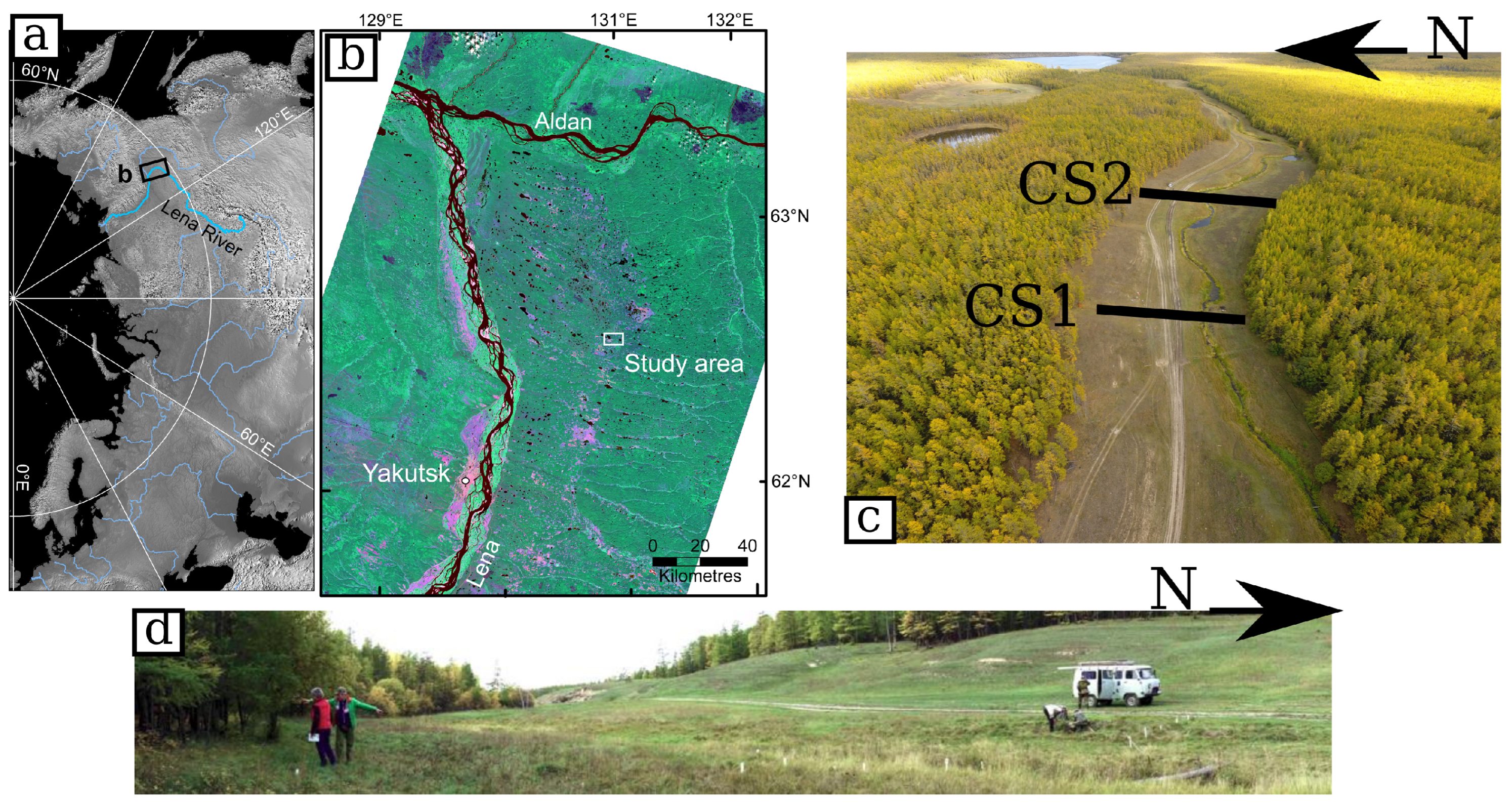
Figure 1. Overview map of the study sites: (a) Location in the northern hemisphere centered on Siberia; (b) Yakutia region; (c) aerial view of the valley looking to the west, with the river and the 2 transects of interest (CS1 and CS2 are 60 m), picture taken in September 2018; (d) panoramic picture of the CS1 transect (oriented SSW-NNE) with the scale given by the truck and the two persons on the left-hand side. Picture taken in September 2017.
Remotesensing 15 02524 g001
Figure 2. Uncrewed Aerial Vehicle imagery-derived results of the area of interest. (a) Visible spectrum (Red Green Blue) orthomosaic; (b) digital surface model cropped on the tree area; (c) green chromatic coordinates (see Section 3.2). Black lines CS1 and CS2 mark the transect positions. Coordinates are in meters (UTM zone 52 N). (d,e) are, respectively, RGB orthomosaic and DSM zoomed in the south part of CS2. The (e) associated colorbar is different to (b).
Remotesensing 15 02524 g002
Figure 3. Modeled domain geometries for (a) CS1 and (b) CS2, including temperature measurement network (red crosses) and classification for surface temperature boundary conditions (BC) for four zones (river, shaded zone, mixed zone, sunny zone), and (c) the associated one year daily temperature time-series averaged over the available seven years of monitoring data, serving as model boundary conditions.
Remotesensing 15 02524 g003
Figure 4. Time series acquired at four monitoring depths (sensor S1 at 1m depth, sensor S2 at 2 m depth, sensor S3 at 3 m depth, and sensor S4 at 4 m depth ) at two positions on CS1, (a) F8 left bank and (b) F3 in the riverbed (see Figure 3a for borehole positions). Dashed vertical black lines indicate the time of the geophysical surveys.
Remotesensing 15 02524 g004
Figure 5. Surface parameter extracted from UAV-derived data and electrical resistivity over the first 1 m soil depth extracted from ERT inversion results along (a) CS1 and (b) CS2 (see Figure 2 for position). The profiles are oriented SW–NE. Top: topography (black), GCC (green); bottom: surface orientation (black) and average electrical resistivity of the first meter (red). Forest area and river zones are represented in green and blue, respectively. The standard deviation values associated with the spatial sampling are indicated in dashed lines.
Remotesensing 15 02524 g005
Figure 6. ALD of different isotherms resulting from thermal modeling at the end of the thawing period on the 15th of September of the average year along (a) transect CS1 and (b) transect CS2. Each color is associated with an isotherm.
Remotesensing 15 02524 g006
Figure 7. Geophysical results on transect CS1 in September 2017. (a) Migrated GPR radargram with AL depth measured with direct piezometer (white circles). The inset compares AL depths were retrieved by both methods. (b) Electrical resistivity model obtained using ERT data. The red line is at the GPR main reflector position in (a), and the purple circles show the positions of temperature sensors. The white circles show the positions of AL depth measured in the tubes.
Remotesensing 15 02524 g007
Figure 8. Resistivity model obtained using ERT data on CS2 acquired in September 2018. The red line is at the GPR main reflector position considered at the base of the active layer.
Remotesensing 15 02524 g008
Figure 9. Resistivity profiles with depth at different distances along transect CS1 (see Figure 7). The river is at 25 m along the transect. (a) Resistivity profiles for September 2017, (b) resistivity profiles comparison for the years 2017 and 2018. Red dashed lines are the GPR main reflector positions.
Remotesensing 15 02524 g009
Figure 10. Inverted electrical resistivity versus temperature measured on site along CS1 for the two field campaigns in 2017 and 2018. Error bars correspond to (±0.25 °C) and spatial variability of the resistivity on a 0.5 m circle centered on the thermal sensor position. Names of the sensors correspond to those presented in Figure 5 and their positions are recalled on the inset.
Remotesensing 15 02524 g010
Disclaimer/Publisher’s Note: The statements, opinions and data contained in all publications are solely those of the individual author(s) and contributor(s) and not of MDPI and/or the editor(s). MDPI and/or the editor(s) disclaim responsibility for any injury to people or property resulting from any ideas, methods, instructions or products referred to in the content.