Article

Assessment of Swarm Kinematic Orbit Determination Using Two Different Double-Difference Methods

Faculty of Geoscience and Environmental Engineering, Southwest Jiaotong University, Chengdu 611756, China
*
Author to whom correspondence should be addressed.
Remote Sens. 2023, 15(10), 2669; https://doi.org/10.3390/rs15102669
Submission received: 6 April 2023 / Revised: 12 May 2023 / Accepted: 18 May 2023 / Published: 20 May 2023
(This article belongs to the Section Satellite Missions for Earth and Planetary Exploration)

Abstract

:
The Swarm mission aims to study the principle and change regularities of the Earth’s magnetic field. Precise orbit determination is essential to the successful implementation of the mission and relevant scientific research. This article focuses on using two different double-difference methods to improve the accuracy of Swarm kinematic orbit determination. The accuracy of the kinematic orbit determination relies entirely on the space-borne observation data, independent of any dynamic parameters. The article analyzes the data quality of the Swarm space-borne global positioning system (GPS) receiver and presents a detailed introduction to the data pre-processing algorithms. The double-difference observation gathering and the applied orbit determination strategy using two different double-difference methods are discussed. The results of the kinematic orbits under different solar cycle conditions are presented, along with an evaluation based on analysis of GPS carrier phase residuals, subtracting from the post-processed orbits, and assessment with satellite laser ranging (SLR) measurements. The results show that the accuracy of the kinematic orbit determination is at the centimeter level for the three Swarm satellites’ orbit solutions. The daily root mean square (RMS) values of the three satellites’ phase residuals remain at around the 6 mm level. The RMS values of the position residuals between the kinematic orbits and the reduced dynamic orbits released by the European Space Agency (ESA) are at about the 2–3 cm level. The external evaluation with SLR measurements shows a good agreement with the ESA level, with the RMS values of the SLR residuals for kinematic orbits around 2 cm.

1. Introduction

The computation of precise orbits for satellites in the low earth orbit (LEO) is an essential precondition to complete important scientific tasks such as ocean monitoring, earth gravity field model recovery, electromagnetic field exploration, topographic mapping, and atmospheric and space environment detection [1]. LEO satellite precise orbit determination (POD) can be divided into three approaches: kinematic orbit determination, dynamic orbit determination, and reduced dynamic orbit determination. During the past few years, since the continuing evolution of space-borne global positioning system (GPS) technology, the accuracy of kinematic precision orbit determination can reach the centimeter level [2,3,4,5,6,7,8,9]. It has been demonstrated that using kinematic positions is better suited for independent gravity field recovery. This is because kinematic positions are obtained from GPS measurements taken at different times, which allows for a larger separation between the positions and reduces the correlation between the observations. This makes the data more appropriate for independent analysis. In addition, kinematic orbit determination is a purely geometrical algorithm to study the motion of satellites. This algorithm does not use any information from the gravity field or LEO dynamic parameters. By contrast, the anomalous dynamic parameters will assimilate some gravitational orbital disturbances and impact the kinematic positions [10,11].
The European Space Agency (ESA) ‘s Earth Explorer Swarm mission consists of three satellites with different orbital altitudes [12]. The constellation was successfully launched on 22 November 2013 and provided Earth observations. The mission was granted an extension until the end of 2021. Swarm is dedicated to producing a comprehensive and precise examination of the magnetic field, including its variation over time. This is achieved through a constellation of satellites equipped with advanced magnetometers and other cutting-edge instruments [13]. Swarm A and Swarm C were initially positioned to fly in close proximity to each other at the equator, separated by a distance of 150 km. Both satellites were placed in orbit at an altitude of approximately 460 km. Meanwhile, Swarm B was placed in a higher orbit, with an initial altitude of about 510 km. In fact, as the extension of time, all three satellites’ orbits will undergo a natural decay after experiencing drag, the decay will be much more pronounced for the lower pair satellites [14]. Each satellite has a set of seven core instruments installed on it. Theseinclude the vector and scalar magnetometers for measuring the Earth’s magnetic field’s direction and strength, the Langmuir probe and thermal ion imager to measure the Earth’s electric field, the accelerometer for measuring the non-gravitational accelerations affecting the Swarm satellites, and the GPS receiver and laser retro-reflectors for orbit determination and validation [15].
Each of the Swarm satellites is loaded with two dual-frequency eight-channel GPS receivers manufactured by RUAG Space, a main and a redundant one [14]. The ESA provides Level 1b and Level 2 data products related to orbits with high accuracy. The Level 1b products contain space-borne GPS observation data and satellite attitude data. The Level 2 products contain corrected and calibrated accelerometer observations and time series of precise science orbits (PSOs) of each satellite. The PSOs consist of kinematic orbit and reduced dynamic orbit solution, and both orbits are calculated by the GPS high-precision orbit determination software tools (GHOST) [16] combined with observation files and external data from IGS, IERS, and CODE. The reduced-dynamic orbit products offer both position and velocity solutions with a smooth 10-s integer sampling, whereas the kinematic orbit products solely offer position information with non-integer time stamps [14]. The kinematic orbits have a sampling rate of 1 Hz and depend on the frequency of the GPS receiver. Additionally, a brief description detailing the accuracy of the two orbit types is contained in the Level 2 product. The accuracy of the final reduced dynamic orbit is less than 3 cm but is released at least 13 days later (generally 21 days) due to the use of precise ephemeris (ultrafast-3 h delay, fast-17 h delay, and final-13 days delay).
After the launch of Swarm satellites, Swarm POD has gained a great deal of attention. Zangerl et al. carried out a performance evaluation of the Swarm GPS receiver, presented the in-orbit measurement data, and compared it with ground-test results [17]. Several modifications have been made to the onboard receiver settings to further boost the tracking performance, thereby possibly increasing the quality of the results for both kinematic orbits and reduced-dynamic orbits [18]. Van den IJssel et al. explained the adopted POD strategies for the reduced dynamic approach and kinematic approach and presented the first precise science orbits based on over a year of GPS observations [14]. Zehentner developed an approach for kinematic POD with raw GPS measurements and validated that the proposed method can produce orbit positions as accurate or better than existing approaches [10,11]. Allende-Alba et al. provided a brief overview of the half-cycle ambiguity resolution process utilized in generating carrier phase observations and implemented the strategies for integer ambiguities fixing and the space baseline determination between Swarm A and Swarm C [19,20]. Zhang proposed kinematic and reduced dynamic POD methods for the Swarm satellites based on space-borne GPS precise point positioning measurements, and then the acceleration approach was adopted to recover the gravity field model [21,22]. Montenbruck et al. showed the PSO results from four years of GPS observation data by using a refined model and reprocessing technique. Following an assessment from the analysis of SLR observation, and overall, a 50% performance improvement can be inferred for the kinematic orbits and a 30% performance improvement can be inferred for the reduced-dynamic orbits [23]. Kermarrec et al. proposed a new way using the Matérn covariance family to reduce the influence of ionospheric scintillations [24] on Swarm orbit determination [25]. Ren and Schön developed software using precise point positioning batch least-squares estimation for kinematic POD and computed the 1-year orbit results of Swarm satellites with the software [26]. Li et al. processed the space-borne GPS data from Swarm and Sentinel-3 satellites via the undifferenced ambiguities resolution method for real-time LEO kinematic orbit determination [27]. Bezděk et al. showed that GPS data quality and calculation results from the Swarm mission have similar accuracy as the GRACE mission, thus the Swarm mission could fill the blank in gravity field observation before the launch of GRACE Follow-On in August 2017 [28,29,30,31,32]. Encarnação et al. demonstrated the best combination method for generating an optimal model based on the products provided by three institutes (ASU, Bezděk et al., 2016 [28]; AIUB, Jäggi et al., 2016 [30]; IfG, Zehentner et al., 2015 [10]). The quality of the Swarm-derived gravity field model is proven to be good [33]. Lück et al. utilized Swarm data from 37 months of kinematic orbit to derive and investigate time-variable gravity field and ocean mass variations [34].
In GPS data processing, the double-difference model is one of the most commonly used basic methods [35]. However, with the increase in multi-frequency, multi-mode, and station network scale, the calculation time of the double-difference model increases exponentially. To break the computational bottleneck of the double-difference model, some scholars have proposed precise point positioning (PPP) based on the zero-difference model [36]. PPP can obtain the absolute coordinates of the target by single-station processing, which significantly reduces the calculation time of data processing. For most of the research mentioned above, the POD strategies are based on zero-difference approaches. With the rapid improvement of computer performance in recent years, the double-difference model is preferred for solving in the absence of extra-long baselines. Hwang et al. used double-difference methods for processing KOMPSAT-2 and SAC-C satellite GPS observations, which satisfied the requirement of 1-m accuracy [37]. Švehla et al. used the double-difference method for the CHAMP satellite [3]. Jäggi et al. discussed the impact of fixed ambiguities on the double-difference baselines and obtained good orbital results for GRACE through different double-difference baseline solutions [4]. Kang et al. used zero-difference and double-difference observation values for reduced dynamic orbit determination for GRACE and GRACE-FO satellites and analyzed the results, the three-dimensional accuracy of the two orbits was better than 2 cm [38,39].
In this article, we focus on increasing the accuracy of Swarm kinematic precise orbit determination using two different double-difference methods. The orbit determination process with this method is a bit complicated and depends on the quality of the observation data. The satellite-borne GPS data in 2021 were processed to validate the proposed methods under different solar cycle conditions. The year 2021 is currently in the upward period of the solar cycle 25 [40], and the level of solar activity is gradually increasing, with a consequent increase in ionospheric activity. The deterioration of signal reception caused by the ionosphere can significantly reduce the signal-to-noise ratio, making it difficult to capture and track signals, thereby reducing positioning accuracy [25,41]. In severe cases, strong ionospheric activity can cause the navigation receiver to lose lock and signal interruption. The first ground enhancement of the 25th solar cycle occurred on 28 October 2021 [42]. Therefore, a special analysis was conducted on the impact of ionospheric activity. This article is divided into the following sections to explain. First, Section 2 introduces the double-difference observation gathering and satellite-borne GPS data pre-processing. Then, the applied POD strategy using the double-difference method is discussed. Afterward, the results of the orbit calculations are presented in Section 3, and the accuracy and reliability of the obtained results are evaluated through three methods: analysis of space-borne GPS phase observation residuals, subtracting from the ESA’s PSOs, and assessment with satellite laser ranging measurements. Section 4 is about an analysis and discussion of the results. Finally, a summary is given in Section 5.

2. Materials and Methods

2.1. Observation Analysis

This article analyses the quality of GPS observations offered by space-borne GPS receivers which provides a basis for data pre-processing. At the beginning of the mission, the Swarm constellation provided 10-s GPS observation, but no simultaneous GPS measurement epoch, which complicates the baseline determination between the Swarm constellation. Therefore, on 15 July 2014, the instrument setting was modified, and the three Swarm satellites delivered 1-s GPS observation. Each Swarm satellite has eight channels which means that the Swarm satellite supports tracking up to 8 GPS satellites simultaneously. For analyzing daily observation data, we calculated the number of tracked satellites and plotted them as a histogram. The total number of daily epochs approached to or was equal to 86,400. Figure 1 shows the GPS tracking performance for all three Swarm satellites from 1 January to 31 December 2021. On 1 November 2021, which is an exception, a malfunction occurred onboard of Swarm C. The quantity of available epochs was only 59,237 due to the anomaly. As indicated from the figure, the GPS receiver tracked eight satellites more than 80% of the time on most days of 2021. The average percent of tracking eight GPS satellites for the three Swarm satellites are 83.52%, 82.38%, and 83.67%, respectively. The reduction in the number of visible satellites was accompanied by a decline in the quality of GPS observation data. We observed a decline in data quality during one day in late November and the second half of December. This could account for the medium-high solar activity. A specific analysis will be conducted in the following section.
The true observation epoch of the Swarm constellation is expressed in GPS time and pretty close to an integer second. Therefore, the timestamp of the PSOs published by ESA is also pretty close to an integer second. In order to process single- and double-difference GPS data, an appropriate interpolation of IGS precise ephemeris and clocks is required. The high-order polynomial interpolation suffers from a potentially random noise process that is not appropriate for the clock parameters [43]. We choose to implement a simple linear interpolation method.

2.2. Data Pre-Processing

Suppose that there are Swarm satellite receiver  r  and GPS satellite  p , then, neglecting part of the errors, the simplified pseudo and phase basic observation equations are as follows
P r p = ρ r p + c ( t r t p ) + c ( b r b p ) + I r p + ε P
L r p = ρ r p + c ( t r t p ) + λ ( B r B p ) + λ N r p I r p + ε L
where  ρ r p  stands for the distance between the GPS satellite  p  and the Swarm receiver  r , measured by pseudo-range observations;  t r  is the receiver clock at the time of signal reception;  t p  is the satellite clock at the time of signal transmission;  b r  and  b p  refer to the code hardware delay of the receiver and satellite, whereas  B r  and  B p  are the receiver-dependent and satellite-dependent phase biases, respectively;  λ  is the wavelength;  N r p  is the phase ambiguity, and  I r p  is the ionospheric delay;  ε P  and  ε L  stand for the sum of random noise. Since the altitudes of the three Swarm satellites are around 500 km, the tropospheric delay is not considered in the observation equation.
The ionosphere-free (IF) combination of pseudo-range and phase observations at a specific epoch can be expressed as
P r , I F p = ρ r p + c ( t r t p ) + c ( b r , I F b I F p ) + ε P , I F = f 1 2 P 1 f 1 2 f 2 2 f 2 2 P 2 f 1 2 f 2 2
L r , I F p = ρ r p + c ( t r t p ) + λ I F ( B r , I F B I F p ) + λ I F N r , I F p + ε L , I F = f 1 2 L 1 f 1 2 f 2 2 f 2 2 L 2 f 1 2 f 2 2
where  b r , I F  and  b I F p  are the IF code hardware delay of receiver and satellite, whereas  B r , I F  and  B I F p  are the IF receiver-dependent and satellite-dependent phase biases, respectively;  λ I F  is the wavelength of IF combination observation;  N r , I F p  is the IF combination phase ambiguity;  ε P , I F  and  ε L , I F  are the sum of IF random noise and multipath effects;  f 1  and  f 2  are the carrier frequencies;  P 1 / P 2  and  L 1 / L 2  are the pseudo range and carrier phase observation, respectively. Since the  t r  and  t p  are estimated by IF combination observations, the code hardware delay of the GPS satellite and Swarm receiver in Equation (3) is assimilated into the clock offsets of the satellite and receiver, respectively, then eliminated. In addition, the phase ambiguity in Equation (4) will absorb both phase bias and the code hardware delay.
The Melbourne-Wübbena (MW) linear combination can eradicate the impact of geometric distance, ionospheric effects, GNSS satellite, and the receiver clock, including the wide-lane part and the narrow-lane part, and finally represented as
L r , M W p = λ W N r , W p + ε M W = f 1 L 1 f 2 L 2 f 1 f 2 f 1 L 1 + f 2 L 2 f 1 + f 2
where  L r , M W p  represents the MW linear combination;  λ W  represents the wavelength;  N r , W p  represents the ambiguity;  ε M W  is the sum of MW measurement noise and multipath errors.
At two continuous observation epochs  t i  and  t i + 1 , the epoch-side phase single-difference observable is defined by
S D r , I F p ( t i , t i + 1 ) = ρ r p ( t i + 1 ) ρ r p ( t i ) + c ( Δ t r Δ t p ) + Δ ε P , I F
where  Δ  is the operator for epoch difference in corresponding parameters. The single-difference between epochs eliminates the ambiguities but ignores the correlation between the phase observations. If the number of epochs of the observed arc segment is less; then, the coordinate correction  [ Δ X Δ Y Δ Z ]  cannot be calculated. In addition, Swarm orbit is required to have a higher precision priori orbit.
With the extension of the observation period, the possibility of cycle slip formation is increased. First of all, the methods of cycle slip detection are briefly introduced below. According to the results of kinematic point positioning using the ionosphere-free (IF) combination pseudo range observation, we can calculate the position and receiver clock bias of the Swarm satellite  X = [ X Y Z c t r ] . Then, the residual information is used to judge whether the pseudo-range observations are grossly inaccurate. Similarly, the various parameters of the position and receiver clock offset  X = [ Δ X Δ Y Δ Z Δ c t r ]  are estimated using a least squares algorithm, the cycle slips can be precisely detected in the current epoch through the IF combination epoch carrier phase single-difference observations. The observation equations of pseudo-range gross error and phase cycle slip can be modeled as follows
{ P = f ( X , Y , Z , c t r ) + Δ ε P , I F Δ L = g ( Δ X , Δ Y , Δ Z , Δ c t r ) + Δ ε L , I F
where  P  is the IF combination pseudo-range,  Δ L  is the epoch carrier phase single-difference observations.  [ X Y Z c t r ]  and  [ Δ X Δ Y Δ Z Δ c t r ]  are the parameters to be estimated. In addition to identifying gross errors and detecting cycle slips in the data pre-processing, the difference observation data must be optimized and corrected.
Possible configurations for the double-difference approaches are illustrated in Figure 2. The double-difference observation data involves two GPS satellites,  p  and  q , and two receiver stations. First, receiver-side single-difference between receiver stations is employed to eliminate the satellite clock error and satellite-dependent phase biases. Then, satellite-side double-difference is used to eradicate the receiver clock bias and receiver-dependent phase bias as shown in Figure 2 considering two different approaches to generating double difference observation
D D r m , I F p q = ( ρ r p ρ m p ) ( ρ r q ρ m q ) + λ I F Δ N r m , I F p q + Δ ε r m , I F p q
D D a c , I F p q = ( ρ a p ρ c p ) ( ρ a q ρ c q ) + λ I F Δ N a c , I F p q + Δ ε a c , I F p q
The moving baseline mode is used in Equation (9) because the positions of one Swarm satellite are not fixed. When both Swarm satellites are moving, one of the satellites is selected as the base station, and its position is determined through the single-point positioning method. The zero-difference IF combination phase observations can be expressed as Equation (4). The estimated parameters are positions and clock offsets. In order to ensure the accuracy of the reference orbit, numerical integration and iteration are required [21]. Compare reference positions with the final ESA orbits and eliminate the points with a difference greater than 10 cm. Then, the position of another Swarm satellite compared to the base station can be computed on an epoch-by-epoch basis.
When Equation (8) is used, double-difference baselines need to be formed between the Swarm satellite and all IGS ground stations. The positioning accuracy depends not only on the GPS satellite orbit but also on the coordinate accuracy of the ground station. Tropospheric delays must also be considered once ground stations are involved. Precise ephemeris for GPS satellite coordinates should be employed to reduce the broadcast ephemeris errors for the long-distance estimation between Swarm satellites and IGS ground stations. For the corrections not incorporated into the equation, the multipath effect is absorbed into the ambiguities and position coordinates. The IF linear combination is formed to remove the ionosphere terms. The Earth tidal effect and relativistic effect also need to be considered for the long-distance estimation between ground stations and satellites.
Fixing the phase ambiguities to integer values will increase the accuracy of the satellite orbit determination solution [44]. The long baseline processing represents a challenging situation for integer ambiguity resolution. We first used the traditional Kalman filtering algorithm to compute the ambiguity parameters, and the results showed that the fixing rate is very low. It may be caused by the modeling error and divergence of values in the filtering process. Therefore, the ambiguities must be determined epoch-by-epoch for kinematic positioning. The modified least-squares ambiguity decorrelation adjustment (LAMBDA) method has been used for single epoch integer ambiguities least-squares estimation [45]. Suppose the float ambiguity solutions vector  N  in Equations (8) and (9) have been solved,  Q N  is its variance-covariance matrix. The direct purpose is to obtain the integer parameter vector  N ^ , make the least squares residual minimize,
( N N ^ ) T Q N 1 ( N N ^ ) = min
The LAMBDA algorithm changes the ambiguity parameter and its variance–covariance matrix from the original space to a new space by Gauss transformation (so-called z-transformation) and aims to realize the reduction process of ambiguity,
{ Q N ¯ = z T Q N z N ¯ = z T N N ^ ¯ = z T N ^
Q N  and  Q N ¯  are symmetric positive definite. For the convenience of calculation, Cholesky factorization technique is usually used with them,
Q N = L T D L
Q N ¯ = L ¯ T D ¯ L ¯
where  L  and  L ¯  are lower triangular matrices, and  D  and  D ¯  are diagonal matrices.
L = ( 1 l 21 1 l n 1 l n 2 1 ) , L ¯ = ( 1 l ¯ 21 1 l ¯ n 1 l ¯ n 2 1 )
D = ( d 1 d 2 0 0 d n ) , D ¯ = ( d ¯ 1 d ¯ 2 0 0 d ¯ n )
There are two main steps in reduction process: first, to make the absolute values of the off-diagonal elements in the  L ¯  matrix less than or equal to 0.5, and second, to sort the diagonal elements of the  D ¯  matrix in descending order. The detailed methods are presented in [45]. After reducing the correlation between ambiguity parameters, the efficiency of the ambiguity search can be greatly accelerated. By resolving the float IF combination ambiguities, the positioning solution can subsequently be realized as long as the number of synchronous observation satellites is more than or equal to 4.

2.3. Kinematic Orbit Determination Strategy

For Swarm B, 50 IGS ground stations were selected based on station performance and geographic distribution to generate the double-difference model. The coordinates of ground stations calculated by CODE and corresponding tropospheric delays are introduced. Nevertheless, for the low-pair Swarm satellites, we take a different approach by forming a baseline of variable length to compute their kinematic position coordinates with Equation (9). These baselines were constrained to a maximum cross-track spacing of around 160 km at the equator. The distances from Swarm B to the ground stations are more than 500 km. These two types of double-difference methods represent a complex situation for integer ambiguity fixing and orbit determination due to the potential ionospheric and tropospheric delays in GPS observations. The Melbourne-Wübbena (MW) linear combination algorithm is used to determine carrier phase integer ambiguities. The algorithm works by first solving the wide-lane ambiguities of the MW combination. The wide-lane (WL) ambiguities are the difference in the number of whole cycles between the transmitted and received signals. Once the WL ambiguities are resolved, the narrow-lane (NL) ambiguities are solved by substituting the WL ambiguities into the equation of IF combination phase observations. In the process of ambiguity determination, the ambiguity should be fixed as an integer as possible. This means that the ambiguity should be resolved in such a way that it is as close to a whole number as possible. The resolved integer ambiguities are then employed as known parameters in kinematic orbit determination formulas using IF observation models. This allows for the computation of kinematic position coordinates using only carrier phase observations with fixed integer ambiguities. This significantly improves the accuracy of the positioning information obtained from GPS technology.
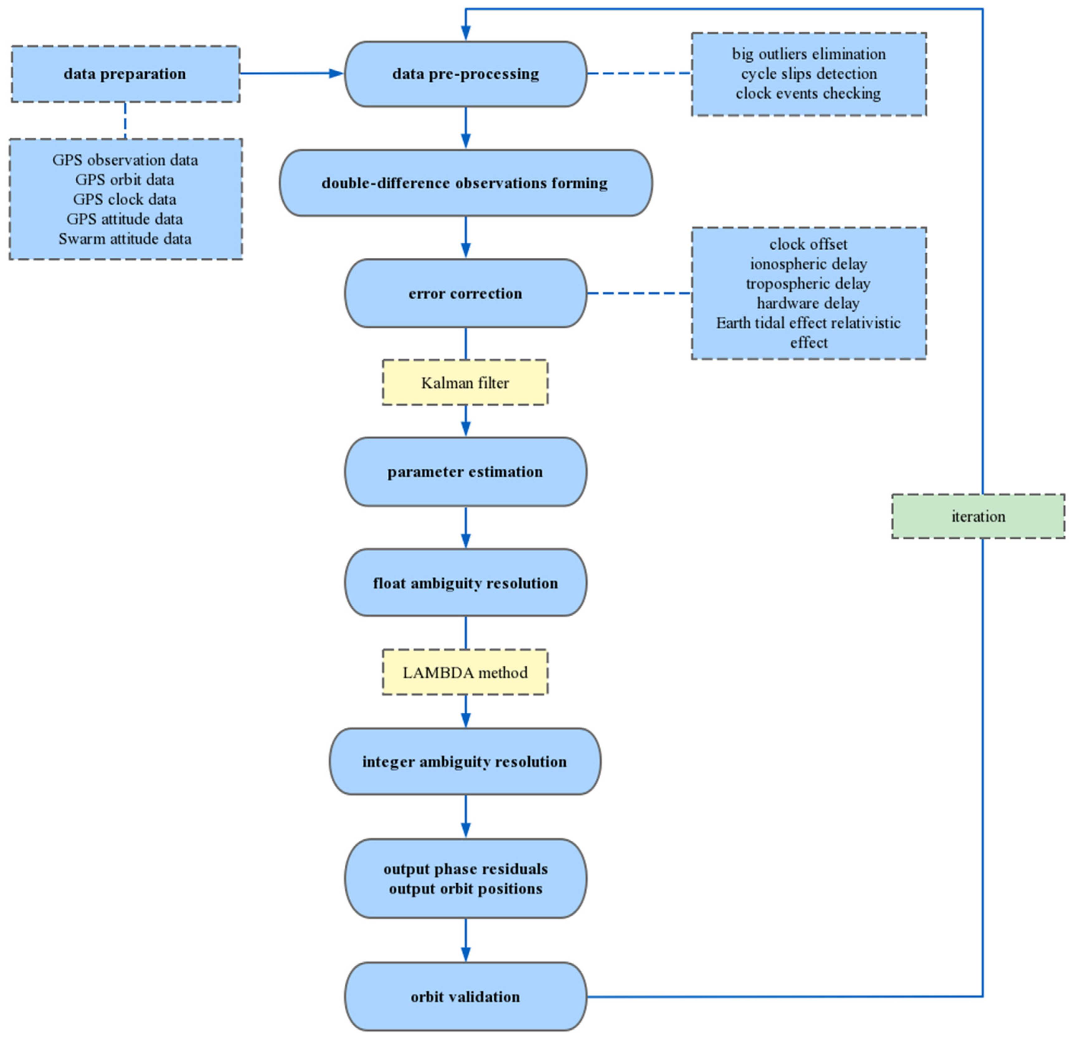
By utilizing the data processing algorithms mentioned in Section 2.3, the first-order ionospheric effect which accounts for over 99% of the whole ionospheric influence [46] is eliminated through the IF linear combination of GPS code and carrier observations. Receiver coordinates and phase ambiguities are then estimated to determine the double-difference parameters. The flow chart of orbit determination is shown in Figure 3. In this article, we utilize the final GPS orbits and high-rate 5-s GPS satellite clock corrections provided by the IGS analysis center. Additionally, we account for the absolute GPS transmit antenna phase center bias and variation in accordance with the igs14.atx file. The attitude data of the Swarm constellation need to be transformed from the satellite frame to the Earth center Earth fixed coordinates system. Throughout the mission lifetime, the satellite center of mass will experience slight movement with fuel consumption. The actual values of the center of mass position are also contained in the ESA PSO products. Finally, the elevation cut-off angle is set to zero for making full use of all observations. Table 1 showed the POD strategy, which details the measurement model and reference frame used for the Swarm kinematic orbit determination.

3. Results

Based on the processing standards described above, the time series of three kinds of kinematic orbits for the three Swarm satellites have been generated from 1 January to 31 December 2021:
  • zero-difference (ZD) kinematic POD;
  • double-difference (DD) kinematic POD without ambiguity resolution;
  • double-difference kinematic POD with ambiguity resolution.
The zero-difference orbit that meets the accuracy requirements is mainly used as an a priori orbit for a double-difference baseline solution. In theory, the accuracy of fixed ambiguity solutions is higher than that of float ambiguity solutions. The double-difference orbits with ambiguity resolution are the final results. As part of this section, the accuracy of the calculations is evaluated and contrasted with precise science orbits from ESA and satellite laser ranging (SLR) measurements. According to ESA documents, the kinematic and reduced dynamics orbit determination are carried out using the Bernese software. The Bernese software performs orbit determination operations based on zero-difference ionosphere-free observations. Further evidence of the quality of kinematic orbits was obtained by analyzing phase residuals as well. The contrast with reduced-dynamic orbits and independent SLR measurements is an external assessment of the orbits. The residuals of GPS observations provide another internal validation of the calculations.

3.1. Ambiguity Resolutions

In order to complete the task of improving the success rate of fixing ambiguities, we adopted a method of selecting an optimal subset of ambiguities and attempted to fix ambiguities multiple times within an epoch. Specifically, when the radio test verification has failed, we removed the satellite with the smallest weight (weighted according to elevation angle) and attempted to fix the ambiguity again. If the ambiguity was still not resolved, we continued removing the satellite with the lowest weight and repeated the process until there were no more satellites available or the ambiguity was successfully resolved. This section analyzes the ambiguity-fixing effect of Swarm satellites from the fixing rate and the changes in phase residuals before and after the fixed ambiguity. Figure 4 shows the results of the fixing ambiguity rate in 2021, which is the proportion of successfully fixed double difference ambiguities to all double difference ambiguities. Through applying this method, the WL ambiguity fixing rates reached 99% for the majority of days in 2021. The average fixing rates of NL ambiguity are 94–95%. Figure 5 demonstrates the mean value of the daily phase residuals before and after the fixed ambiguity. After fixing the ambiguity, the phase residuals of all three satellites increased significantly. The float ambiguities can absorb some other unmodeled errors, whereas the fixed ambiguities make the ambiguity parameters constrained and unable to absorb other errors. Therefore, the phase residuals of the float solutions are slightly larger than that of the fixed solutions.

3.2. Carrier Phase Residuals

The carrier phase residual of GPS observations is the difference between the predicted value and the observed value. It can be used to measure the accuracy of the observations and evaluate the internal consistency of the kinematic orbit solutions. The phase residuals were similar to the noise level of the observation when the observations are of satisfactory quality and pre-processed properly [22]. The mean values of daily RMS error of the phase residuals for three kinds of kinematic orbits are shown in Table 2. There are significant differences between the three kinds of orbits. The RMS values of zero-difference phase residuals remain at around 4 mm, which is smaller than that of the double-difference phase residuals. This indicates that the accuracy of the double-difference orbits is higher than that of the zero-difference orbits.
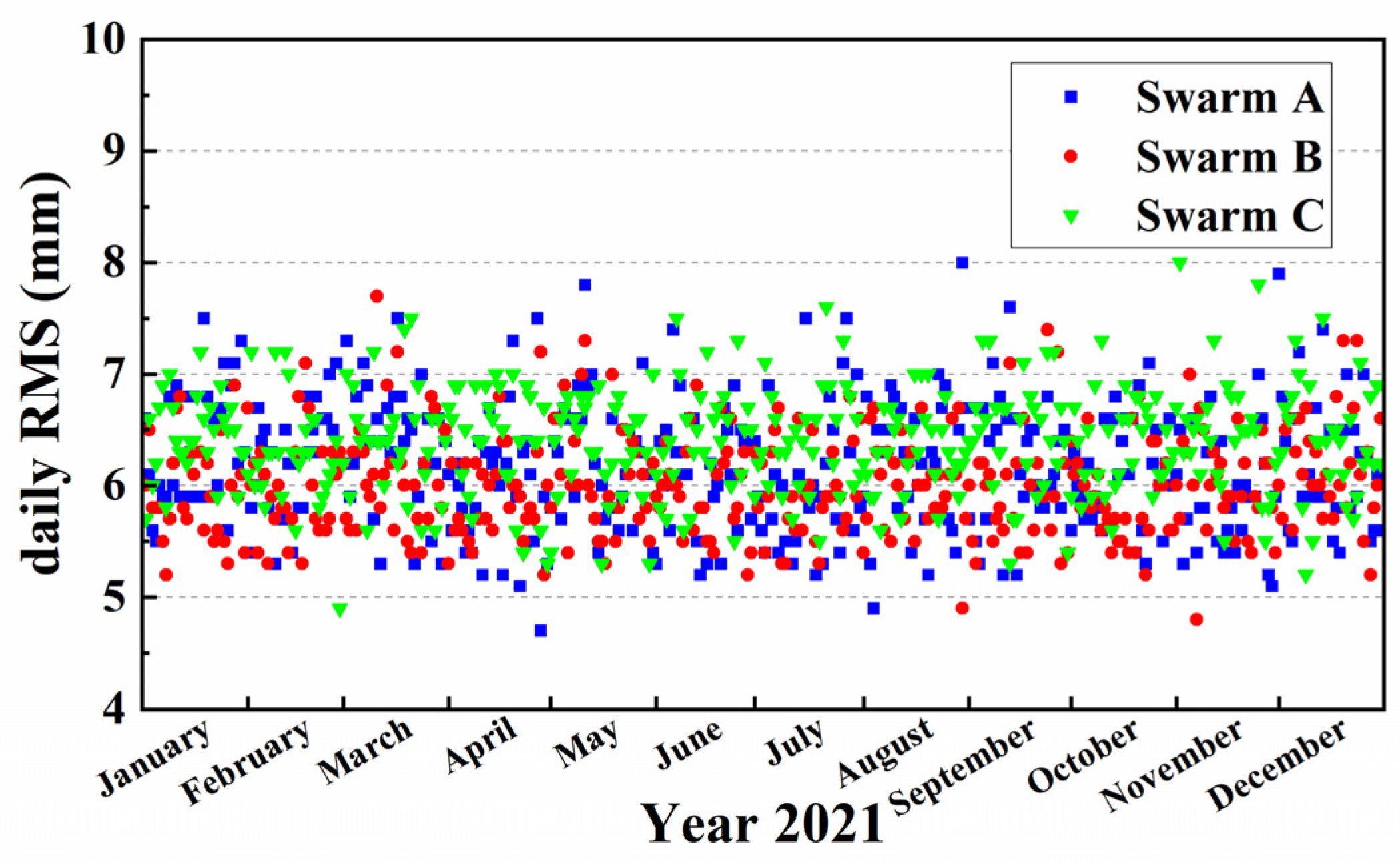
The detailed daily RMS values of the IF carrier phase observation residuals for final orbits in 2021 are shown in Figure 6. On 1 November at 10:27 UTC, an anomaly has been registered on board Swarm C. As a result, the carrier phase residuals have been affected (the daily RMS is 20 mm). For the rest, the average of the daily RMS for Swarm A, B, and C are 6.2 mm, 6.0 mm, and 6.4 mm, respectively. As expected, the RMS of three satellite GPS phase residuals are kept at around the 6 mm level and indicate that the observations are accurate.

3.3. Differences with Reduced Dynamic Orbit Products

The Faculty of Aerospace Engineering at Delft University of Technology is responsible for Swarm satellite precise science orbit determination. The reduced-dynamic orbit is calculated by GHOST software, and the orbit is checked by the observation data of the SLR station on the ground, with a precision of less than 2 cm. The products of the orbit determination have been published on the ESA website: http://swarm-diss.eo.esa.int (accessed on 23 March 2023). According to the orbit determination strategy given above, the results of three kinds of kinematic orbits are compared with those of ESA-reduced dynamic orbits. The statistical results for daily RMS values are presented in Table 3. The differences of the final double-difference fixed resolutions in all three directions are significantly reduced. The accuracies of the final orbits have been improved by 0.8–1.1 cm and 0.4–0.6 cm in three directions compared to the ZD and DD-float results. In the 3D direction, the accuracy of Swarm A has been improved by 35.2% and 17.4%, respectively, Swarm B has been improved by 37.5% and 20.7%, respectively, and Swarm C has been improved by 36.3% and 16.8%, respectively.
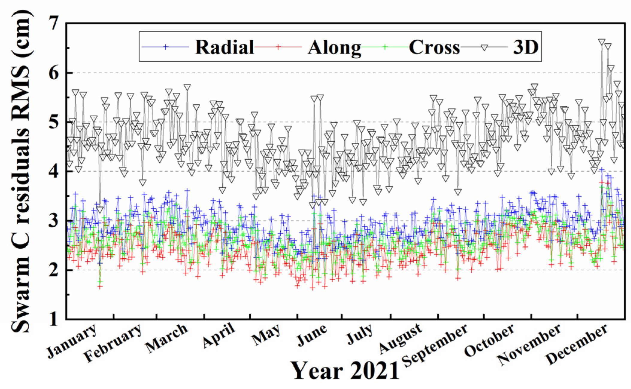
Figure 7, Figure 8 and Figure 9 show the detailed daily RMS of final position residuals for Swarm satellites with respect to ESA-reduced dynamic orbits in three directions. During 2021, the daily RMS values for Swarm A and Swarm C are prone to larger fluctuations, especially in late December, whereas Swarm B is relatively smoother. For the low pair Swarm A and Swarm C, the mean daily RMS of the difference between our kinematic orbit and reduced-dynamic orbit released by ESA in radial, along-track, and cross-track directions are around 2.9 cm, 2.5 cm, and 2.6 cm, respectively. The average of the daily RMS values for Swarm B is about 2.60 cm, 2.13 cm, and 2.45 cm in three directions. The computed Swarm B kinematic orbits are better than Swarm A and C due to their higher quality of observations. Furthermore, compared with the along-track and cross-track directions, the mean RMS values for the radial direction have lower accuracy. This may be caused by the weak observation geometry. The radial direction is also usually not well determined in kinematic orbit determination because the receiver clock corrections must be estimated at the same time as the kinematic positions [14]. On the whole, the mean 3D RMS values of the position residuals between kinematic calculations and reduced-dynamic orbits are below 4.7 cm for Swarm A and C and below 4.2 cm for Swarm B, which can satisfy the requirement for precision (cm level) and have application for gravity field recovery.

3.4. SLR Residuals

The calculated kinematic orbits are also compared against SLR measurements. The precision of millimeters to centimeters can be achieved with fully independent optical distance observations between the Swarm satellite and tracking station by using the SLR system [47,48]. In this way, the differences between measured and modeled values, or in other words, the SLR residuals, can be used to validate not only the precision but also the accuracy of satellite orbits. SLR observations are typically received from the International Laser Ranging Service (ILRS) tracking stations.
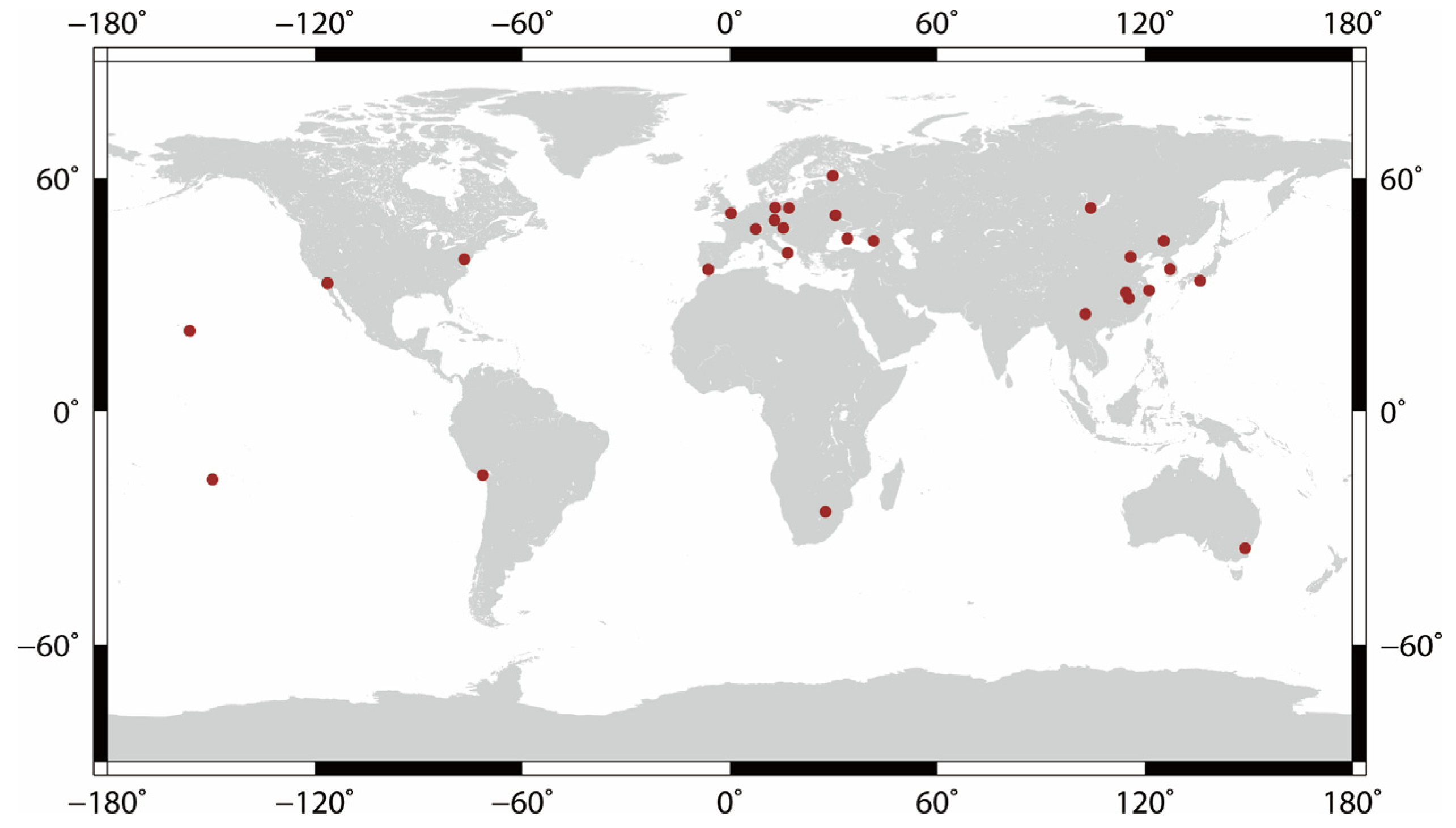
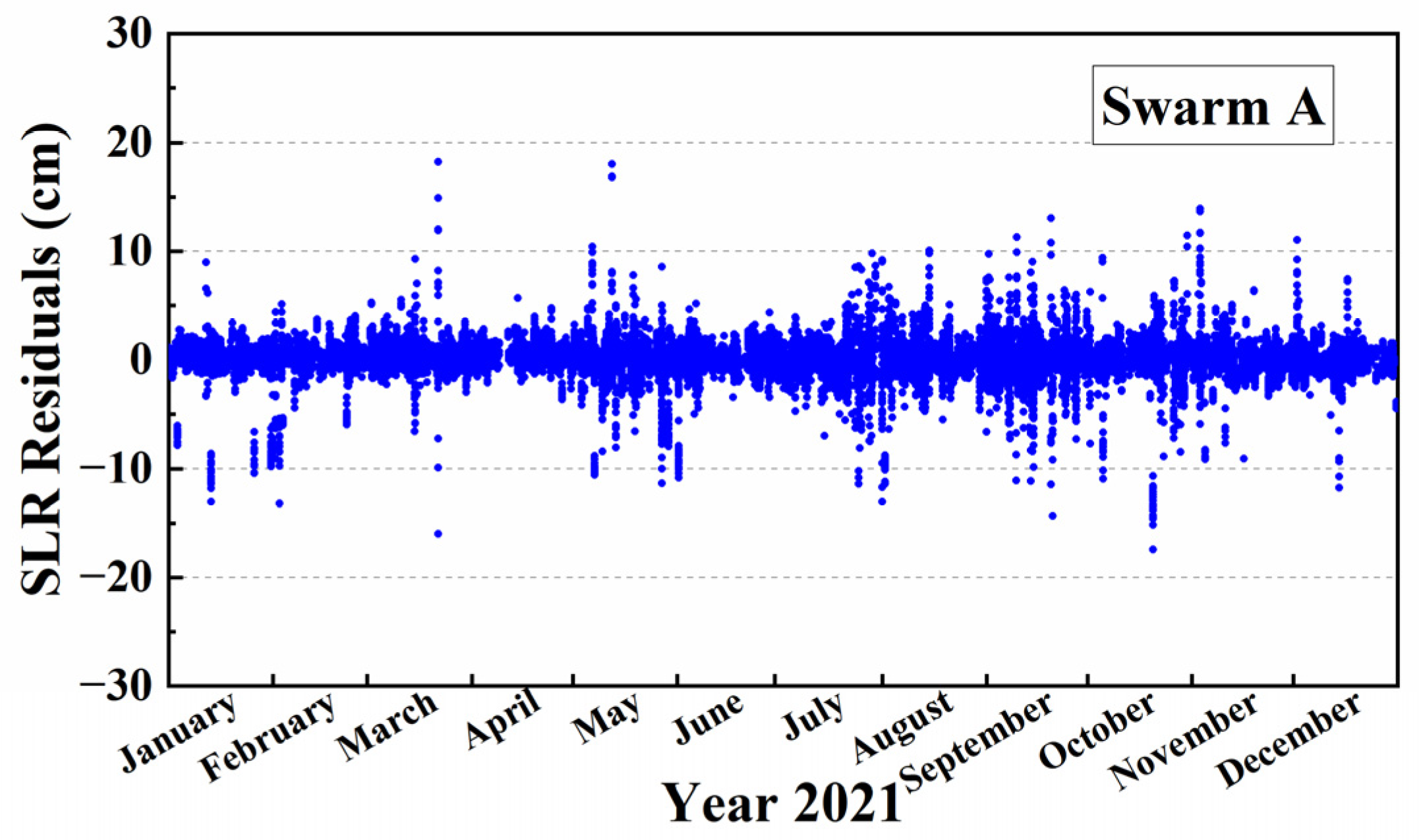
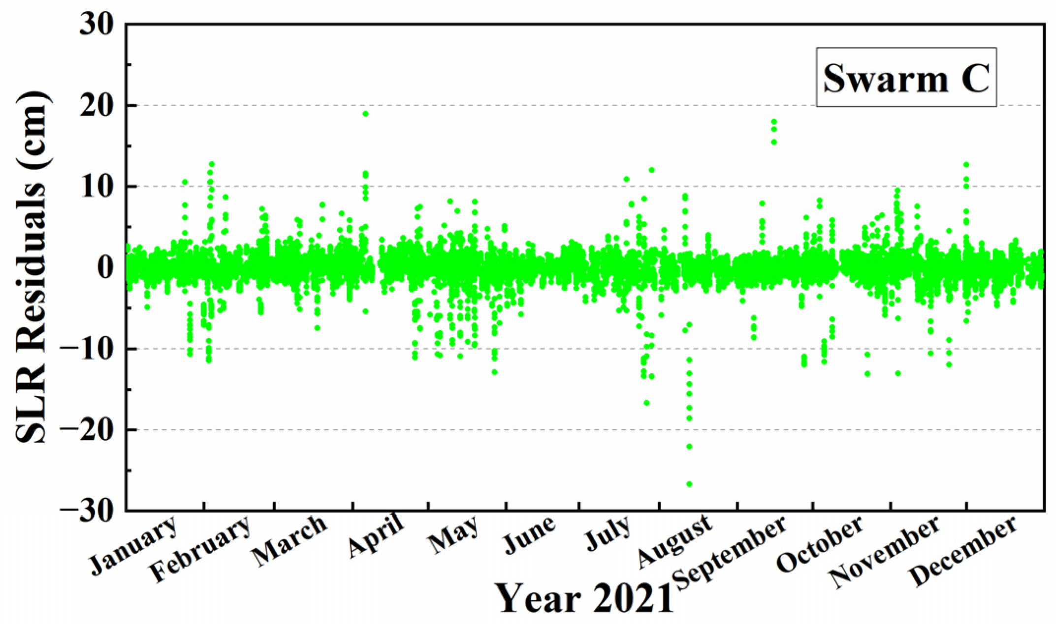
During the study period, there are 28 ground tracking stations that provided available SLR data. The global distribution of these 28 stations is given in Figure 10. The data from Wuhan station are all unavailable. The total number of normal points for the three Swarm satellites are 28,516, 82,126, and 26,952, respectively. More normal points are from Swarm B since it flies in a higher orbit. A moderate separation between Swarm A and Swarm C results in common station visibility. The computed kinematic solutions are first polynomially interpolated to the observed time of the SLR observations. Next, with consideration of the tropospheric delay, relativistic effects, solid Earth tides, and oceanic loads, the distances between the kinematic orbits and the ILRS stations are calculated and compared with the laser ranges. In order to detect outliers that may still exist in the SLR measurements, a screening threshold of 20 cm was used for the residuals. The SLR residuals for the three Swarm satellites during 2021 are shown in Figure 11, Figure 12 and Figure 13. The mean RMS values of SLR residuals are summarized in Table 4. It is worth mentioning that the residual values solved based on the SLR stations located in China are relatively large. For most SLR observations, the residuals between the kinematic orbits and SLR measurements are under the 5 cm level. The RMS value for Swarm A’s kinematic orbits is 1.8 cm, Swarm B is 2.1 cm, and Swarm C is 1.7 cm, respectively.

4. Discussion

For the assessment of the proposed double-difference methods, the three kinds of Swarm kinematic orbits were listed from 1 January to 31 December 2021. The zero-difference model is efficient in solving the problem but requires an accurate error correction model. On the contrary, the double-difference model can effectively weaken or eliminate the same kind of error sources, such as the GPS satellite clock offset and receiver clock offset. As expected, the accuracy of the final double-difference model with ambiguity resolution is higher than the zero-difference model and float resolution. However, it is inevitable that solving double-difference observations requires a significant amount of computational time and storage space. Analysis of the final ionosphere-free carrier phase residuals suggests that the mean daily RMS values for all three Swarm satellites are at around the 6 mm level. The carrier phase residuals under different solar cycle conditions remained below 9 mm and stayed at a satisfactory level, showing strong internal consistency. A comparison with the reduced-dynamic orbits released by ESA shows the mean daily RMS of the orbit differences in radial, along-track, and cross-track directions are around 2.9 cm, 2.5 cm, and 2.6 cm, respectively, for Swarm A and Swarm C. The average of the daily RMS values are about 2.60 cm, 2.13 cm, and 2.45 cm in three directions for Swarm B. For most SLR observations, the residuals between the kinematic orbits and SLR measurements are under the 5 cm level. The RMS values of SLR residuals for the three Swarm satellites’ kinematic orbits are 1.8 cm, 2.1 cm, and 1.7 cm, respectively, showing a very good agreement with the ESA level. For Swarm B, an improved orbit condition is apparent. It is also worth mentioning that the daily RMS of the position residuals for the low pair satellites has comparatively great fluctuation than Swarm B.
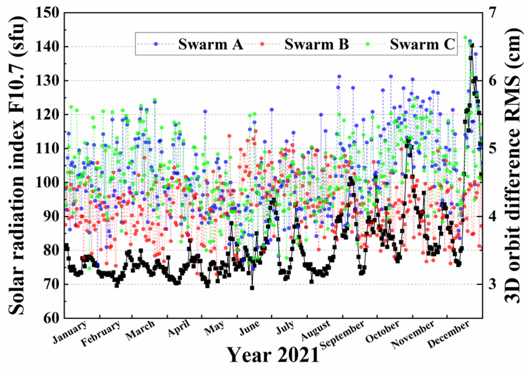
Solar activity has a significant impact on signal communication and satellite navigation. Strong solar activity increases the concentration of electrons and ions in the ionosphere, which increases thermospheric density and atmospheric drag, thus affecting satellite operations. The solar radiation index F10.7 is often used to indicate the intensity of solar activity. F10.7 is the radio radiation flow of the sun at 10.7 cm wavelength (2800 MHz), and its unit is sfu (1 sfu = 1 × 10⁻²² W·m−2·Hz−1). The value of the solar radiation index F10.7 can properly reflect the level of ionospheric conditions. As the value of F10.7 increases, the ionospheric scintillations which are disturbed by solar activity will be more intense [21]. In order to apprehend whether the kinematic orbits are impacted by ionospheric activities and further verify the effectiveness of the kinematic orbit determination strategy proposed above, we did an analysis of the F10.7 index. The data of F10.7 used in this article come from the National Centers for Environmental Information (NCEI) of the National Oceanic and Atmospheric Administration (NOAA): https://www.ngdc.noaa.gov (accessed on 23 March 2023). The average daily F10.7 index in 2019 is 69.7 sfu, in 2020, it was 73.8 sfu, and in 2021 it was 81.8 sfu. Figure 14 represents the sequence diagram of the solar radiation index F10.7 in 2021, and the data show that the overall level of solar activity is gradually rising. We can find that index F10.7 fluctuated between 110 sfu and 150 sfu from 16 December to 29 December (DoY 350-363), showing that the ionospheric activity during this time is relatively intense. This may explain why the daily RMS values for the low pair satellites are highly volatile in late December.
Figure 14 also shows the difference between the final double-difference orbit and the ESA-reduced dynamic orbit in 3D. We discussed the statistical method of the position difference to demonstrate the impact of the F10.7 index on the daily RMS variations. One of the statistical indicators of the strength of a monotonic relationship between paired data is Spearman’s correlation coefficient rs [49]. Spearman correlation analysis describes the correlation of two variables by a linear equation and does not require a priori information of the original data. It is a non-parametric statistical program that has a wide range of applications in mathematical statistics. The correlation coefficient rs and the p-value are computed and entered in Table 5. The significance test results are referred to as the p-value, if the p-value is small enough, we can be more certain that the observed correlation is not due to chance or random variation. A smaller p-value suggests a higher level of confidence that there is a correlation between kinematic orbits and ionospheric scintillations. The bigger absolute values of rs reflects the more relevant the correlation. As shown in Table 5, the rs of three directions range from 0.2 to 0.3 for the low pair satellites, which indicates the F10.7 index is in weak relativity to orbit residuals. However, the rs values for Swarm B are approximately equal to zero and show there is almost no correlation between the radio radiation flow of the sun and Swarm B kinematic orbit residuals.
Furthermore, we calculated the position residuals between the obtained kinematic orbits and the PSO products provided by ESA in intense ionospheric activity (sfu ≥ 110) and in relatively peaceful periods (sfu < 110). The results are shown in Table 6. In the high ionosphere active period, the mean daily RMS values of the difference between two orbit types in the radial direction are 3.38 cm, 2.61 cm, and 3.39 cm for three Swarm satellites, and 2.94 cm, 2.17 cm, and 2.90 cm, respectively, in the along-track direction. In the cross-track direction, the mean daily RMS are 3.09 cm, 2.47 cm, and 2.98 cm, respectively. The mean values of daily RMS in three directions are all larger than in a peaceful period, whereas the changes for Swarm B were not significant.
From the above studies, it is worth mentioning that the daily RMS values of the difference with the PSO products change little for Swarm B, with comparatively great fluctuation for Swarm A and Swarm C, especially in late December. This can be interpreted that Swarm B has a higher flight orbit, and the effect of the ionosphere is weaker than the low pair satellites.

5. Conclusions

In this study, we discussed the approach for determining the kinematic precise orbits with two different double-difference methods, one applied to the low pair satellites and the other applied to Swarm B. Swarm kinematic orbits are generated with moving base and ground stations, respectively. The accuracy and reliability of kinematic orbit rely on the quality of GPS data; therefore, an extensive analysis of GPS data was first performed. Although only eight channels are available for the Swarm constellation, the average percent of tracking eight GPS satellites for three Swarm satellites are 83.52%, 82.38%, and 83.67%, respectively. After processing all the GPS observations, we found that the ambiguities could not be fixed effectively by the Kalman filtering approach. The final WL and NL ambiguity fixing rates reached over 99% and 94% for the Swarm constellation by adopting a program of selecting an optimal subset of ambiguities and attempting to fix ambiguities multiple times within an epoch.
After evaluating the orbit quality, the overall results of the Swarm satellites’ kinematic orbits determination accord with the requirement precision (cm level). Compared to the zero-difference orbits, the accuracy of Swarm satellites was improved by 35.2%, 37.5%, and 36.3%, For the double-difference orbits without ambiguity resolutions, the accuracy was improved by 17.4%, 20.7%, and 16.8%, respectively. The daily RMS values of the IF phase residuals for Swarm satellites were maintained at about the 6 mm level. In contrast, the RMS values of the position residuals with the reduced-dynamic orbits offered by ESA are at about the 2–3 cm level in three directions, respectively. Compared to the SLR measurements, the RMS values of the SLR residuals for kinematic orbits are about 2 cm.
Ionospheric scintillations occur when ionospheric activity becomes intense. GPS receiver operations can be interrupted or degraded, contributing to the position difference between kinematic orbits and reduced-dynamic orbits showing a larger fluctuation. The changes in ionospheric activity are rapid in late December, and for Swarm A and Swarm C, the orbit residuals are strongly perturbed. Swarm B has a higher flight orbit than the low-pair satellites, so it is less affected by the influence of the ionosphere. In addition, ithere were weak monotonic relationships between the F10.7 index and the low pair satellites’ kinematic orbit residuals that were identified through statistical analysis. In a peaceful period, the mean daily RMS of positions residuals between the obtained kinematic orbits and ESA reduced-dynamic orbits in the along-track direction is 2.86 cm and 2.91 cm for Swarm A and Swarm C. Thecross-track directions are 2.45 cm and 2.41 cm, and the radial directions are 2.62 cm and 2.61 cm, respectively. However, in periods with strong ionosphere solicitations, the mean daily RMS are 3.38 cm, 2.94 cm, and 3.09 cm for Swarm A and 3.39 cm, 2.90 cm, and 2.98 cm for Swarm C in three directions. Notwithstanding, ionospheric scintillations do not disturb the carrier phase residuals much.
As expected, using both double-difference methods under different solar cycle conditions satisfies the requirement of centimeter accuracy in the three Swarm satellite orbit solutions and has application value for gravity field determination. Although this article has made a systematic study of Swarm satellite observation data quality and double-difference kinematic orbit determination, some useful conclusions have been obtained. However, there are still some shortcomings that need further research and improvement. For example, in phase residual analysis, it is also necessary to study the inherent effects of phase residual change, multipath error, and observation noise. For zero-difference kinematics orbit determination, the performance of the error processing model needs to be improved. Consider adding dynamic models to achieve reduced dynamic orbit determination.

Author Contributions

Conceptualization, Y.X. and R.Z.; methodology, Y.X. and R.Z.; software, R.Z.; validation, W.C., X.L. and B.Z.; formal analysis, R.Z.; data curation, R.Z.; writing—original draft preparation, R.Z.; writing—review and editing, Y.X. and S.X.; visualization, Y.X.; supervision, Y.X.; project administration, Y.X.; funding acquisition, Y.X. All authors have read and agreed to the published version of the manuscript.

Funding

This research was supported by the National Natural Science Foundation of China (grant number: 41674028) and the Sichuan Science and Technology Program (grant number: 2021YFG0339, 2022YFG0169).

Data Availability Statement

The Swarm spaceborne GPS observation data can be downloaded from http://swarm-diss.eo.esa.int (accessed on 23 March 2023). The GPS satellite ephemeris and clock products used in this paper can be downloaded from ftp://ftp.igs.org/pub/product/ (accessed on 23 March 2023). The SLR observation data can be downloaded from ftp://edc.dgfi.tum.de/pub/slr/data (accessed on 23 March 2023). The data of the solar radiation index F10.7 used in this article come from https://www.ngdc.noaa.gov (accessed on 23 March 2023).

Acknowledgments

The authors gratefully acknowledge ESA for the supplying of the Swarm spaceborne GPS observation data, attitude data, and post-processed reduced-dynamic orbits, which are publicly available from http://swarm-diss.eo.esa.int (accessed on 23 March 2023). CODE is appreciated for providing the earth orientation parameters, the GPS satellite ephemeris, high-rate GPS satellite clocks and corrections. Thanks also go to the SLR observation data from the ILRS Data Centers at ftp://edc.dgfi.tum.de/pub/slr/data (accessed on 23 March 2023).

Conflicts of Interest

The authors declare no conflict of interest.

References

  1. Yang, Y. PPP Based Sequential Orbit Determination for Satellites in Low Earth Orbit. Ph.D. Thesis, Northwestern Polytechnical University, Xian, China, 2015. [Google Scholar]
  2. Visser, P.N.A.M.; Van Den Ijssel, J. Aiming at a 1-cm Orbit for Low Earth Orbiters: Reduced-Dynamic and Kinematic Precise Orbit Determination. Space Sci. Rev. 2003, 108, 27–36. [Google Scholar] [CrossRef]
  3. Švehla, D.; Rothacher, M. Kinematic and reduced-dynamic precise orbit determination of low earth orbiters. Adv. Geosci. 2003, 1, 47–56. [Google Scholar] [CrossRef]
  4. Jäggi, A.; Hugentobler, U.; Bock, H.; Beutler, G. Precise orbit determination for GRACE using undifferenced or doubly differenced GPS data. Adv. Space Res. 2007, 39, 1612–1619. [Google Scholar] [CrossRef]
  5. Peter, H.; Jäggi, A.; Švehla, D.; Beutler, G.; Hugentobler, U.; Visser, P. Precise orbit determination for the GOCE satellite using GPS. Adv. Space Res. 2007, 39, 1638–1647. [Google Scholar] [CrossRef]
  6. Weinbach, U.; Schön, S. Improved GRACE kinematic orbit determination using GPS receiver clock modeling. GPS Solut. 2013, 17, 511–520. [Google Scholar] [CrossRef]
  7. Guo, X.; Zhao, Q. A New Approach to Earth’s Gravity Field Modeling Using GPS-Derived Kinematic Orbits and Baselines. Remote Sens. 2019, 11, 1728. [Google Scholar] [CrossRef]
  8. Luo, P.; Jin, S.; Shi, Q. Undifferenced Kinematic Precise Orbit Determination of Swarm and GRACE-FO Satellites from GNSS Observations. Sensors 2022, 22, 1071. [Google Scholar] [CrossRef] [PubMed]
  9. Yang, Z.; Liu, X.; Guo, J.; Guo, H.; Li, G.; Kong, Q.; Chang, X. Relative Kinematic Orbit Determination for GRACE-FO Satellite by Jointing GPS and LRI. Remote Sens. 2022, 14, 993. [Google Scholar] [CrossRef]
  10. Zehentner, N.; Mayer-Gürr, T. Precise orbit determination based on raw GPS measurements. J. Geod. 2016, 90, 275–286. [Google Scholar] [CrossRef]
  11. Zehentner, N. Kinematic Orbit Positioning Applying the Raw Observation Approach to Observe Time Variable Gravity. Ph.D. Thesis, Graz University of Technology, Graz, Austria, 2016. [Google Scholar]
  12. Friis-Christensen, E.; Lühr, H.; Knudsen, D.; Haagmans, R. Swarm–an Earth observation mission investigating geospace. Adv. Space Res. 2008, 41, 210–216. [Google Scholar] [CrossRef]
  13. Olsen, N.; Friis-Christensen, E.; Floberghagen, R.; Alken, P.; Beggan, C.D.; Chulliat, A.; Doornbos, E.; da Encarnação, J.T.; Hamilton, B.; Hulot, G.; et al. The Swarm Satellite Constellation Application and Research Facility (SCARF) and Swarm data products. Earth Planets Space 2013, 65, 1189–1200. [Google Scholar] [CrossRef]
  14. Van Den Ijssel, J.; Encarnacao, J.; Doornbos, E.; Visser, P. Precise science orbits for the Swarm satellite constellation. Adv. Space Res. 2015, 56, 1042–1055. [Google Scholar] [CrossRef]
  15. Visser, P.; Doornbos, E.; van den Ijssel, J.; Teixeira da Encarnação, J. Thermospheric density and wind retrieval from Swarm observations. Earth Planets Space 2013, 65, 1319–1331. [Google Scholar] [CrossRef]
  16. Van Helleputte, T. User Manual for the GHOST Orbit Determination Software, FDS-SUM-3110; Deutsches Zentrum für Luft-und Raumfahrt: Oberpfaffenhofen, Germany, 2004. [Google Scholar]
  17. Zangerl, F.; Griesauer, F.; Sust, M.; Montenbruck, O.; Buchert, S.; Garcia, A. SWARM GPS Precise Orbit Determination Receiver Initial In-Orbit Performance Evaluation. In Proceedings of the ION GNSS+2014, Tampa, FL, USA, 8–12 September 2014. [Google Scholar]
  18. Van Den Ijssel, J.; Forte, B.; Montenbruck, O. Impact of Swarm GPS receiver updates on POD performance. Earth Planets Sp. 2016, 68, 1–17. [Google Scholar] [CrossRef]
  19. Allende-Alba, G.; Montenbruck, O.; Jaggi, A.; Arnold, D.; Zangerl, F. Reduced-dynamic and kinematic baseline determination for the Swarm mission. GPS Solut. 2017, 21, 1275–1284. [Google Scholar] [CrossRef]
  20. Allende-Alba, G.; Montenbruck, O.; Hackel, S.; Tossaint, M. Relative positioning of formation-flying spacecraft using single-receiver GPS carrier phase ambiguity fixing. GPS Solut. 2018, 22, 68. [Google Scholar] [CrossRef]
  21. Zhang, B. Precise Orbit Determination and the Earth Gravity field Recovery by Acceleration Approach for Swarm. Ph.D. Thesis, Wuhan University, Wuhan, China, 2017. [Google Scholar]
  22. Zhang, B.; Niu, J.; Wang, Z.; Xu, F.; Tian, K. Centimeter precise orbit determination for the Swarm satellites via undifferenced kinematic method. Acta Geod. Cartogr. Sin. 2021, 50, 27–36. [Google Scholar] [CrossRef]
  23. Montenbruck, O.; Hackel, S.; van den Ijssel, J.; Arnold, D. Reduced dynamic and kinematic precise orbit determination for the Swarm mission from 4 years of GPS tracking. GPS Solut. 2018, 22, 79. [Google Scholar] [CrossRef]
  24. Buchert, S.; Zangerl, F.; Sust, M.; André, M.; Eriksson, A.; Wahlund, J.E.; Opgenoorth, H. SWARM observations of equatorial electron densities and topside GPS track losses. Geophys. Res. Lett. 2015, 42, 2088–2092. [Google Scholar] [CrossRef]
  25. Kermarrec, G.; Ren, L.; Schön, S. On filtering ionospheric effects in GPS observations using the Matérn covariance family and its impact on orbit determination of Swarm satellites. GPS Solut. 2018, 22, 66. [Google Scholar] [CrossRef]
  26. Ren, L.; Schön, S. PPP-based Swarm kinematic orbit determination. Ann. Geophys. 2018, 36, 1227–1241. [Google Scholar] [CrossRef]
  27. Li, X.; Wu, J.; Zhang, K.; Li, X.; Xiong, Y.; Zhang, Q. Real-Time kinematic precise orbit determination for LEO satellites using zero-differenced ambiguity resolution. Remote Sens. 2019, 11, 2815. [Google Scholar] [CrossRef]
  28. Bezděk, A.; Sebera, J.; Encarnação, J.T.d.; Klokočník, J. Time-variable gravity fields derived from GPS tracking of Swarm. Geophys. J. Int. 2016, 205, 1665–1669. [Google Scholar] [CrossRef]
  29. Richter, H.M.P.; Lück, C.; Klos, A.; Sideris, M.G.; Rangelova, E.; Kusche, J. Reconstructing GRACE-type time-variable gravity from the Swarm satellites. Sci. Rep. 2021, 11, 1117. [Google Scholar] [CrossRef] [PubMed]
  30. Jaggi, A.; Dahle, C.; Arnold, D.; Bock, H.; Meyer, U.; Beutler, G.; van den Ijssel, J. Swarm kinematic orbits and gravity fields from 18months of GPS data. Adv. Space Res. 2016, 57, 218–233. [Google Scholar] [CrossRef]
  31. da Encarnacao, J.T.; Visser, P.; Arnold, D.; Bezdek, A.; Doornbos, E.; Ellmer, M.; Guo, J.; van den IJssel, J.; Iorfida, E.; Jäggi, A. Description of the multi-approach gravity field models from Swarm GPS data. Earth Syst. Sci. Data 2020, 12, 1385–1417. [Google Scholar] [CrossRef]
  32. Schreiter, L.; Montenbruck, O.; Zangerl, F.; Siemes, C.; Arnold, D.; Jäggi, A. Bandwidth correction of Swarm GPS carrier phase observations for improved orbit and gravity field determination. GPS Solut. 2021, 25, 70. [Google Scholar] [CrossRef]
  33. da Encarnação, J.; Arnold, D.; Bezděk, A.; Dahle, C.; Doornbos, E.; van den Ijssel, J.; Jäggi, A.; Mayer-Gürr, T.; Sebera, J.; Visser, P.; et al. Gravity field models derived from Swarm GPS data. Earth Planet Sp. 2016, 68, 127. [Google Scholar] [CrossRef]
  34. Luck, C.; Kusche, J.; Rietbroek, R.; Locher, A. Time-variable gravity fields and ocean mass change from 37 months of kinematic Swarm orbits. Solid Earth 2018, 9, 323–339. [Google Scholar] [CrossRef]
  35. Blewitt, G. Fixed point theorems of GPS carrier phase ambiguity resolution and their application to massive network processing: Ambizap. J. Geophys. Res. Solid Earth 2008, 113, B12410–B12421. [Google Scholar] [CrossRef]
  36. Zumberge, J.F.; Heflin, M.B.; Jefferson, D.C.; Watkins, M.M. Precise point positioning for the efficient and robust analysis of GPS data from large networks. J. Geophys. Res. Solid Earth 1997, 102, 5005–5017. [Google Scholar] [CrossRef]
  37. Hwang, Y.; Lee, B.-S.; Kim, H.; Kim, J. Orbit determination performances using single-and double-differenced methods: SAC-C and KOMPSAT-2. Adv. Space Res. 2011, 47, 138–148. [Google Scholar] [CrossRef]
  38. Kang, Z.; Tapley, B.; Bettadpur, S.; Ries, J.; Nagel, P.; Pastor, R. Precise orbit determination for the GRACE mission using only GPS data. J. Geod. 2006, 80, 322–331. [Google Scholar] [CrossRef]
  39. Kang, Z.; Bettadpur, S.; Nagel, P.; Save, H.; Poole, S.; Pie, N. GRACE-FO precise orbit determination and gravity recovery. J. Geod. 2020, 94, 85. [Google Scholar] [CrossRef]
  40. Bisoi, S.K.; Janardhan, P.; Ananthakrishnan, S. Another Mini Solar Maximum in the Offing: A Prediction for the Amplitude of Solar Cycle 25. J. Geophys. Res. Space Phys. 2020, 125, e2019JA027508. [Google Scholar] [CrossRef]
  41. Aquino, M.; Moore, T.; Dodson, A.; Waugh, S.; Souter, J.; Rodrigues, F.S. Implications of Ionospheric Scintillation for GNSS Users in Northern Europe. J. Nav. 2005, 58, 241–256. [Google Scholar] [CrossRef]
  42. Papaioannou, A.; Kouloumvakos, A.; Mishev, A.; Vainio, R.; Usoskin, I.; Herbst, K.; Rouillard, A.P.; Anastasiadis, A.; Gieseler, J.; Wimmer-Schweingruber, R.; et al. The first ground-level enhancement of solar cycle 25 on 28 October 2021. Astron. Astrophys. 2022, 660, L5. [Google Scholar] [CrossRef]
  43. Montenbruck, O.; Gill, E.; Kroes, R. Rapid orbit determination of LEO satellites using IGS clock and ephemeris products. GPS Solut. 2005, 9, 226–235. [Google Scholar] [CrossRef]
  44. Bertiger, W.; Desai, S.D.; Haines, B.; Harvey, N.; Moore, A.W.; Owen, S.; Weiss, J.P. Single receiver phase ambiguity resolution with GPS data. J. Geod. 2010, 84, 327–337. [Google Scholar] [CrossRef]
  45. Chang, X.W.; Yang, X.; Zhou, T. MLAMBDA: A modified LAMBDA method for integer least-squares estimation. J. Geod. 2005, 79, 552–565. [Google Scholar] [CrossRef]
  46. Hoque, M.M.; Jakowski, N. Estimate of higher order ionospheric errors in GNSS positioning. Radio Sci. 2008, 43, 68–82. [Google Scholar] [CrossRef]
  47. Arnold, D.; Montenbruck, O.; Hackel, S.; Sośnica, K. Satellite laser ranging to low Earth orbiters: Orbit and network validation. J. Geod. 2019, 93, 2315–2334. [Google Scholar] [CrossRef]
  48. Strugarek, D.; Sośnica, K.; Zajdel, R.; Bury, G. Detector-specific issues in Satellite Laser Ranging to Swarm-A/B/C satellites. Measurement 2021, 182, 109786. [Google Scholar] [CrossRef]
  49. Spearman, C. The proof and measurement of association between two things. Int. J. Epidemiol. 2010, 39, 1137–1150. [Google Scholar] [CrossRef] [PubMed]
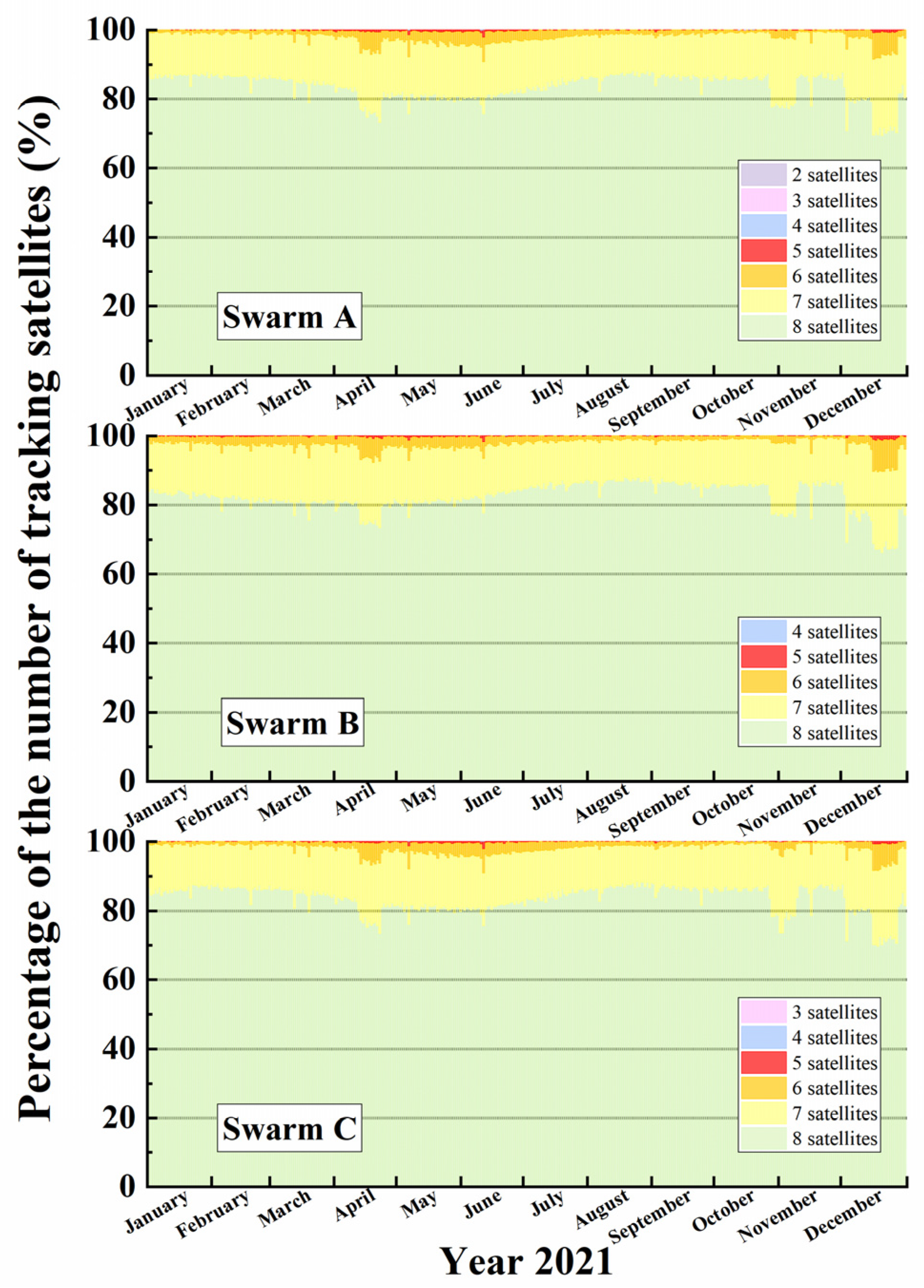
Figure 1. Swarm GPS data tracking observation of the year 2021.
Remotesensing 15 02669 g001
Figure 2. (a) Configurations of double-difference methods for the ground station; (b) Configurations of double-difference methods for satellite-to-satellite.
Remotesensing 15 02669 g002
Figure 3. The flow chart of orbit determination.
Remotesensing 15 02669 g003
Figure 4. The time series of WL and NL ambiguities fixing rates of the Swarm satellites.
Remotesensing 15 02669 g004
Figure 5. The mean daily RMS of the phase residuals of float and fixed ambiguity results.
Remotesensing 15 02669 g005
Figure 6. Daily RMS error of the carrier phase residuals of kinematic orbit determination for all three Swarm satellites during 2021.
Remotesensing 15 02669 g006
Figure 7. The daily RMS of positions residuals for Swarm A with respect to ESA reduced-dynamic orbits in the along-track, cross-track, and radial component for 2021.
Remotesensing 15 02669 g007
Figure 8. The daily RMS of positions residuals for Swarm B with respect to ESA reduced-dynamic orbits in the along-track, cross-track, and radial component for 2021.
Remotesensing 15 02669 g008
Figure 9. The daily RMS of positions residuals for Swarm C with respect to ESA reduced-dynamic orbits in the along-track, cross-track, and radial component for 2021.
Remotesensing 15 02669 g009
Figure 10. The distribution of the SLR tracking stations on the ground.
Remotesensing 15 02669 g010
Figure 11. The SLR residuals for the Swarm A kinematic orbits.
Remotesensing 15 02669 g011
Figure 12. The SLR residuals for the Swarm B kinematic orbits.
Remotesensing 15 02669 g012
Figure 13. The SLR residuals for the Swarm C kinematic orbits.
Remotesensing 15 02669 g013
Figure 14. Solar radiation index F10.7 (black) and 3D orbit difference RMS (blue for Swarm A, red for Swarm B, and green for Swarm C) of year 2021.
Remotesensing 15 02669 g014
Table 1. Summary of the measurement model and reference frame used for the Swarm kinematic orbit determination.
GPS Measurement ModelDescriptions
GPS tracking data1-s ionosphere-free code and phase
GPS orbitsIGS final sp3
GPS clock5-s IGS clk
GPS antenna phase center offsetigs14.atx
Swarm antenna phase center offsetphase center offset (Level 1b)
phase center variations map [18]
Swarm attitudeQuaternion from star camera (Level 1b)
Elevation cut-off angle
Ambiguityfixed
Reference frameOriginOrientation
ITRFcenter of earthX along Greenwich meridian
Y along 90° E meridian
Z towards North pole
GPSRGPSR antenna reference center/
ICRFbarycenter of solar system/
NECreference positionN towards North
E towards East
C towards center of Earth
Swarm Spacecraftantenna reference centerX nominal flight direction
Y sideways (“right”)
Z downwards (nadir)
RTNcenter of satelliteR towards center of Earth
T along track
N cross track
Table 2. Mean of daily RMS error of the carrier phase residuals for all three Swarm satellites during 2021.
SatelliteMean of Daily RMS Error of the Carrier Phase Residuals (mm)
ZDDD-FloatDD-Fixed
Swarm A4.15.76.2
Swarm B4.25.56.0
Swarm C4.55.96.4
Table 3. The mean daily RMS of the difference between the kinematic orbit and ESA reduced dynamic orbit during 2021.
SatelliteModelRadial (cm)Along (cm)Cross (cm)3D (cm)
Swarm AZD3.743.413.626.22
DD-float3.272.933.155.40
DD-fixed2.862.482.624.60
Swarm BZD3.553.063.285.72
DD-float3.082.712.895.02
DD-fixed2.602.132.454.16
Swarm CZD3.983.423.446.27
DD-float3.332.913.065.38
DD-fixed2.912.432.614.60
Table 4. The mean and RMS values of SLR residuals for the Swarm satellites using observations from SLR stations.
SatelliteNumber of Normal PointsMean (cm)RMS (cm)
Swarm A28,5160.101.80
Swarm B82,126−0.182.10
Swarm C26,952−0.031.73
Table 5. Spearman’s correlation between the F10.7 index and orbit difference for the Swarm satellites.
SatelliteRadial AlongCross
rsp-Valuersp-Valuersp-Value
Swarm A0.2726<10−60.2744<10−60.2592<10−6
Swarm B0.02220.67210.04600.38100.02180.6788
Swarm C0.2562<10−40.2876<10−40.2400<10−4
Table 6. The mean daily RMS of the difference between the kinematic orbit and reduced-dynamic orbit under different solar cycle conditions.
SatelliteRadial (cm)Along (cm)Cross (cm)
IntensePeacefulIntensePeacefulIntensePeaceful
Swarm A3.382.862.942.453.092.59
Swarm B2.612.602.172.122.482.45
Swarm C3.392.912.902.412.982.60
Disclaimer/Publisher’s Note: The statements, opinions and data contained in all publications are solely those of the individual author(s) and contributor(s) and not of MDPI and/or the editor(s). MDPI and/or the editor(s) disclaim responsibility for any injury to people or property resulting from any ideas, methods, instructions or products referred to in the content.