Article

The Uncertainty of SNO Cross-Calibration for Satellite Infrared Channels

1
Chinese Academy of Meteorological Sciences, Beijing 100081, China
2
University of Chinese Academy of Sciences, Beijing 100049, China
3
Key Laboratory of Radiometric Calibration and Validation for Environmental Satellites, National Satellite Meteorological Center (National Center for Space Weather), China Meteorological Administration, Beijing 100081, China
4
Innovation Center for FengYun Meteorological Satellite (FYSIC), Beijing 100081, China
5
Key Laboratory of Photoelectronic Imaging Technology and System of Ministry of Education of China, School of Optics and Photonics, Beijing Institute of Technology, Beijing 100081, China
*
Author to whom correspondence should be addressed.
Remote Sens. 2023, 15(13), 3313; https://doi.org/10.3390/rs15133313
Submission received: 7 May 2023 / Revised: 24 June 2023 / Accepted: 26 June 2023 / Published: 28 June 2023

Abstract

:
The on-orbit radiometric calibration is a fundamental task in quantitative remote sensing applications. A widely used calibration method is the cross-calibration based on Simultaneous Nadir Observation (SNO), which involves using high-precision reference instruments to calibrate lower-precision onboard instruments. However, despite efforts to match the observation time, spatial location, field geometry, and instrument spectra, errors can still be introduced during the matching processes and linear regression analysis. This paper focuses on the error generated by sample matching and the error fitting method generated by the sample fitting method. An error propagation analysis is performed to develop a generic model for assessing the uncertainty of the SNO cross-calibration method itself in meteorological satellite infrared channels. The model is validated using the payload parameters of the Hyperspectral Infrared Atmospheric Sounder (HIRAS) and the Medium Resolution Spectral Imager (MERSI) instruments aboard the FengYun-3D (FY-3D). Simulation experiments are performed considering typical bright temperatures, different background fields, and varying matching threshold conditions. The results demonstrate the effectiveness of the proposed model in capturing the error propagation chain in the SNO cross-calibration process. The model provides valuable insight into error analysis in the SNO cross-calibration method and can assist in determining the optimal sample matching threshold for achieving radiometric calibration accuracy.

1. Introduction

Radiometric calibration is a fundamental process in remote sensing that establishes the relationship between the output signal of a remote sensing instrument and the physical quantity of the observed target. It utilizes a standard radiation source or reference signal as a benchmark. The accuracy of radiometric calibration directly affects the quality of quantitative remote sensing products, as it determines the reliability of transforming observed data into meaningful physical measurements [1]. Various methods are employed for radiometric calibration, including laboratory calibration, onboard calibration, and vicarious calibration [2,3,4]. However, relying solely on laboratory calibration is insufficient due to the inability of ground laboratories to perfectly replicate the space environment and the degradation of onboard instrument performance over time following a satellite launch [5,6]. Meanwhile, due to the limitations of space, payload, energy consumption, and technology, some early meteorological satellites did not carry full-optical-path and full-aperture onboard calibrators, or the onboard calibration devices may not work normally [7,8]. Therefore, additional measures are necessary to acquire accurate calibration coefficients.
To address these challenges, the Simultaneous Nadir Observation (SNO) cross-calibration method has emerged as a popular approach for in-orbit vicarious calibration of satellite instruments [9,10,11]. The SNO cross-calibration method involves comparing simultaneous observations between the monitored instrument and a high-accuracy reference instrument, both observing the same area from the same viewing angle. This method offers advantages such as cost-effectiveness and higher calibration frequency; it is thus widely adopted for vicarious calibration, especially in the infrared channels of early meteorological satellites [12,13,14]. The SNO cross-calibration method is particularly valuable in climate studies, enabling long-term observations of subtle changes in the Earth’s atmosphere, oceans, and land surface. Furthermore, it helps identify and mitigate instrumental biases and uncertainties, thereby improving the accuracy and reliability of the collected data.
Understanding the uncertainty associated with the cross-calibration of satellite infrared channels is crucial for ensuring accurate and reliable climate observations. Previous studies have primarily focused on evaluating the accuracy of the SNO method in terms of its ability to provide reliable calibration results. For example, as the reference radiometric benchmarks for cross-calibration and its accuracy assessment, Advanced Very-High-Resolution Radiometry (AVHRR), Moderate Resolution Imaging Spectroradiometer (MODIS), and Infrared Atmospheric Sounding Interferometry (IASI) have been applied in the FY-2 and FY-3 meteorological satellites [15,16,17], while MODIS is applied in land, environmental, and ocean satellites [18,19]. The assessment of uncertainty in SNO cross-calibration results involves the consideration of various factors, including measurement noise from the monitored instrument, calibration uncertainties from the reference instrument, data matching errors, and uncertainty in regression analysis, all of which require further investigation. Recently, the actual observation data of two specific satellites during the calibration were analyzed to assess the uncertainty of calibration results [20,21,22]. However, the quantification and analysis of uncertainty within the calibration process itself have not been extensively explored [23,24].
The objective of this study is to assess the uncertainty associated with the SNO cross-calibration method itself, with a specific focus on satellite infrared channels. The analysis centers on the uncertainties arising from sample matching (temporal matching, spatial matching, angular matching, and spectral matching) and regression analysis methods employed during the calibration process. To achieve this, this paper proposes a method based on the Guide to the Expression of Uncertainty in Measurement (GUM) framework [25]. By analyzing the key factors that contribute to uncertainty and deriving theoretical equations, we aim to provide a comprehensive understanding of the sources of uncertainty and their impacts on calibration results. Rather than relying on actual satellite data, our approach utilizes satellite parameters such as the spatial resolution, spectral resolution, and the point spread function (PSF) to construct tailored datasets for evaluating uncertainty. The generalized model presented in this study offers a comprehensive framework for assessing the uncertainty of the SNO cross-calibration method in satellite infrared channels. It provides valuable guidance in selecting appropriate temporal and spatial matching thresholds, ensuring environmental uniformity and determining optimal parameters for reference instruments. Our research aims to enhance the accuracy and reliability of satellite-based infrared measurements by quantifying the uncertainties in the calibration process.
Subsequently, the parameters of the Hyperspectral Infrared Atmospheric Sounder (HIRAS) and the Medium-Resolution Spectral Imager (MERSI) onboard the FengYun-3D (FY-3D) were utilized to construct simulation datasets and examine the uncertainties of the SNO cross-calibration method under different parameter scenarios. These datasets allow for an examination of the SNO cross-calibration method’s uncertainty under various parameter settings. Simulated SNO cross-calibration matching data are generated by parameter of PSF, instrument spatial resolution, spatial uniformity, and considerations for errors in the fitting method for sample points. Furthermore, the study investigates the sensitivities of target radiance to temporal matching, spatial matching, angular matching, and spectral drift.
This article is organized as follows. In Section 2, we provide a summary of the SNO cross-calibration method and the associated uncertainty assessment model. Section 3 describes the design of the conducted simulation test. Moving on to Section 4, we present the results of the sensitivity analysis on error propagation. The assessment of radiometric calibration uncertainty is presented in Section 5, followed by discussions and conclusions in Section 6 and Section 7.

2. SNO Cross-Calibration and Uncertainty Assessment Model

2.1. SNO Cross-Calibration Method

The crucial aspect of SNO cross-calibration is to ensure that the monitored and reference instruments observe the same target simultaneously and under identical observation geometry conditions. To fulfill this requirement, the matching data of these two instruments must satisfy various criteria, including temporal matching, spatial matching, angular matching, spectral matching, uniform background field testing, and regression analysis [26,27].
The SNO cross-calibration process is shown in Figure 1, comprising the following key parts: (1) Temporal Matching: this step involves matching the observations of the reference and monitored instruments in time. It is crucial to ensure that both instruments capture data simultaneously to minimize temporal differences that may introduce uncertainties. The time difference threshold is set to determine the acceptable deviation between the observations; (2) Spatial Matching: spatial matching focuses on aligning the reference and monitored instruments’ observations in space. It involves selecting the target area for observation based on the spatial resolution relationship between the two instruments. However, positioning deviations may occur, leading to changes in the calibration results. The spatial matching threshold is set to determine the acceptable positioning deviation; (3) Angular Matching: angular matching aims to ensure that the reference and monitored instruments observe the same target under similar observation geometry conditions. This includes matching the viewing angles and geometries of the instruments to reduce uncertainties introduced by angular differences; (4) Spectral Matching: spectral matching involves comparing and aligning the spectral characteristics of the reference and monitored instruments’ observations. Spectral drift, or variations in the instrument’s spectral response over time, can introduce uncertainties. Spectral matching ensures that the observations are adjusted to account for these spectral differences.
By addressing these different aspects of matching, the SNO cross-calibration method aims to reduce uncertainties caused by temporal, spatial, angular, and spectral differences between the reference and monitored instruments. The calibration results obtained through this process help improve the accuracy and reliability of satellite measurements, particularly in infrared channels used for Earth observation.
Linear regression analysis methods are commonly employed in cross-calibration to establish the radiation relationships between the monitored and the reference instruments. Equation (1) illustrates the relationship between the radiance of the monitored instrument after calibration and the radiance of the monitored instrument before calibration.
L c a l i b r a t e d = a × L t a r g e t + b
Here, Lcalibrated represents the radiance of the monitored instrument after calibration, Ltarget denotes the radiance of the monitored instrument before calibration, and a and b are the slope and intercept, respectively. a and b are obtained from the regression relationship between the radiance of the monitored and the radiance of the reference instruments.

2.2. Derivation of a Generalized Model for SNO Cross-Calibration Uncertainty Assessment

The Guide to the Expression of Uncertainty in Measurement (GUM) is a valuable resource for ensuring accurate and reliable data. The following is a comprehensive operational flow based on the GUM.
(1) Define the quantity being measured: Before expressing any uncertainty, it is necessary to define the quantity being measured and its unit of measurement. This is important because the unit of measurement affects the calculation of uncertainty.
(2) Identify sources of uncertainty: The next step is to identify all possible sources of uncertainty that could affect the measurement. Examples include variations in the instrument, environmental factors, or human error.
(3) Quantify the uncertainty: To quantify the uncertainty, statistical methods such as standard deviation or confidence intervals can be used. The method chosen should be appropriate for the type of data being analyzed.
(4) Express the uncertainty: The uncertainty should be expressed in the same units as the measured quantity. It is also important to indicate the level of confidence associated with the uncertainty, such as a 95% confidence level.
(5) Report the result: Finally, the measured quantity and its uncertainty should be reported together, such as “the weight of the object is 5.00 ± 0.05 g”.
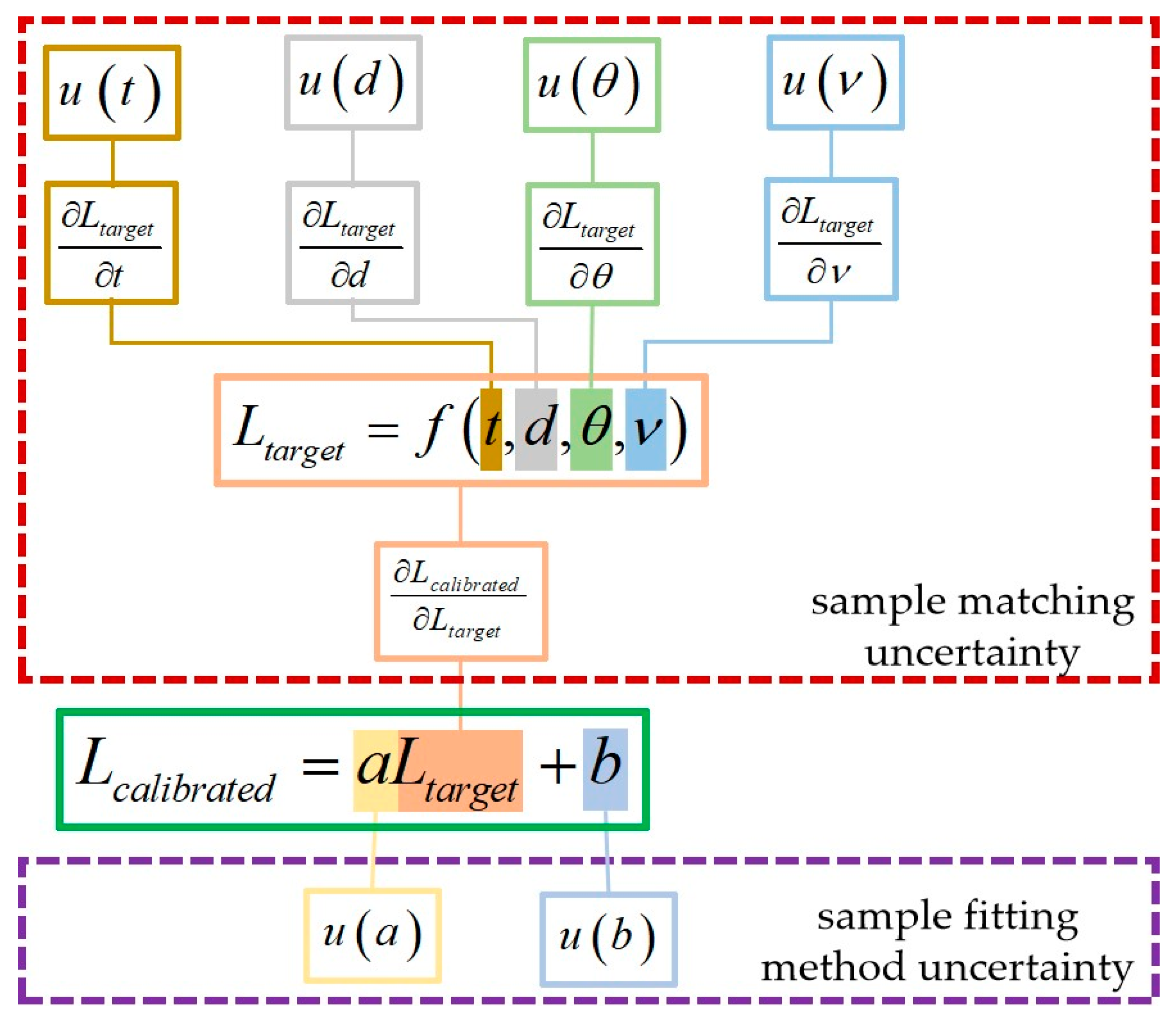
Following this operational flow based on the principles outlined in the GUM helps ensure accurate and reliable measurement data and facilitates effective communication of uncertainty in measurement. The uncertainty assessment method for the satellite IR channel SNO cross-calibration method itself is constructed based on the GUM principles. A flow chart of the SNO cross-calibration uncertainty is shown in Figure 2, where the uncertainty assessment includes both sample matching uncertainty assessment and sample fitting method uncertainty assessment.
According to Figure 2, the errors in the matching samples primarily arise from variations in the observation time (Δt), spatial position (Δd), satellite’s zenith angle (Δθ), and spectral characteristics (Δν) between the monitored instrument and the reference instrument during calibration. These errors are quantified by the standard uncertainties u(t), u(d), u(θ), and u(ν), respectively. It is important to note that all input parameters are assumed to be independent and have an equal probability of occurrence. Consequently, the standard uncertainty u(Ltarget) of the matched pixel radiance of the monitored instrument in the matching process can be calculated using Equation (2) [20,21,25].
u L t a r g e t = u t × L t a r g e t t 2 + u d × L t a r g e t d 2 + u θ × L t a r g e t θ 2 + u ν × L t a r g e t ν 2
Here, ∂Ltarget/t, ∂Ltarget/d, ∂Ltarget/θ, and ∂Ltarget/ν represent the sensitivities of the radiance to temporal matching, spatial matching, angular matching, and spectral matching, respectively. These sensitivities, also known as sensitivity coefficients, can be calculated through the sensitivity analysis of each factor. In the threshold range, it is assumed that each parameter has an equal occurrence probability, and thus, the parameter differences can be assumed to follow a rectangular distribution [24]. Based on this assumption, the standard uncertainty of each parameter can be expressed using the following equations:
u t = Δ t / 3
u d = Δ d / 3
u θ = Δ θ / 3
u ν = Δ ν / 3
In Equations (3)–(6), Δt, Δd, Δθ, and Δν represent the thresholds for time matching, spatial matching, angular matching, and spectral matching, respectively. These thresholds determine the acceptable range of differences in each parameter during the matching process.
In addition to the sample matching error, the regression analysis method introduces uncertainty into the calibration results, primarily arising from the slope and intercept of the regression line. The uncertainty of the fitting results can be calculated using Equation (7) [28]:
u L c a l i b r a t e d = L c a l i b r a t e d L t a r g e t u L t a r g e t 2 + L c a l i b r a t e d a u a 2 + L c a l i b r a t e d b u b 2 + 2 L c a l i b r a t e d a L c a l i b r a t e d b u a u b r a , b
In Equation (7), ∂Lcalibrated/∂Ltarget, ∂Lcalibrated/a, and ∂Lcalibrated/b represent the sensitivity coefficients of the calibrated pixel radiance of the monitored instrument (Lcalibrated) to the radiance of the monitored instrument before calibration (Ltarget), slope (a), and intercept (b), respectively. These sensitivity coefficients can be obtained by taking the partial derivatives of Equation (1). The correlation coefficient between the slope and intercept is denoted as ra,b, while u(a) and u(b) represent the standard uncertainties of the slope and intercept, respectively. These equations can be found in ISO/TS 28037 [29], which provides guidelines for the use of straight-line calibration functions.
The uncertainties for a and b can be calculated using Equations (8) and (9), respectively, while the correlation coefficient ra,b is determined by Equation (10).
u a = S e n / i = 1 n L t a r g e t , i 2 i = 1 n L t a r g e t , i 2
u b = S e i = 1 n L t a r g e t , i 2 / i = 1 n L t a r g e t , i 2 i = 1 n L t a r g e t , i 2
r a , b = i = 1 n L t a r g e t , i / n i = 1 n L t a r g e t , i 2
Here, Ltarget,i represents the radiance of the ith matched pixel from the monitored instrument prior to calibration. The variable n denotes the total number of matched pixels. The residual variance of the fitted curve, Se2, is determined using Equation (11) for calculation.
S e 2 = i = 1 n L r e f e r e n c e , i L c a l i b r a t e d , i 2 / n 2
Here, Lreference,i represents the radiance of the ith matched pixel from the reference instrument, and Lcalibrated,i represents the radiance of the ith matched pixel from the monitored instrument after calibration. The values of Lcalibrated,i are obtained by interpolating the fitted curve for each Ltarget,i, as described in Equation (1).
By substituting Equations (8)–(11) into Equation (7), we obtain a generalized model for SNO cross-calibration error assessment. This model combines the sample matching error and sample regression error to provide a comprehensive evaluation of the calibration errors:
u L c a l i b r a t e d = a × u L t a r g e t 2 + L t a r g e t × u a 2 + u b 2 + 2 L t a r g e t × u a × u b × r a , b

3. Design of Simulation Test

3.1. HIRAS and MERSI

The Medium-Resolution Imaging Spectrometer is one of the main optical imaging payloads on the FY-3 series satellites. The second generation of MERSI (MERSI-II) has improved in its performance compared to that of the first generation, forming a double satellite network with the FY-3C series, which greatly improves China’s meteorological satellite observation capability. MERSI-II is equipped with a total of twenty-five channels, including sixteen visible-near infrared channels, three short-wave infrared channels, and six medium–long wave infrared channels. Among them, six channels have a sub-satellite point resolution of 250 m, and the remaining nineteen channels have a resolution of 1000 m. Table 1 provides a comprehensive list of the specific bands.
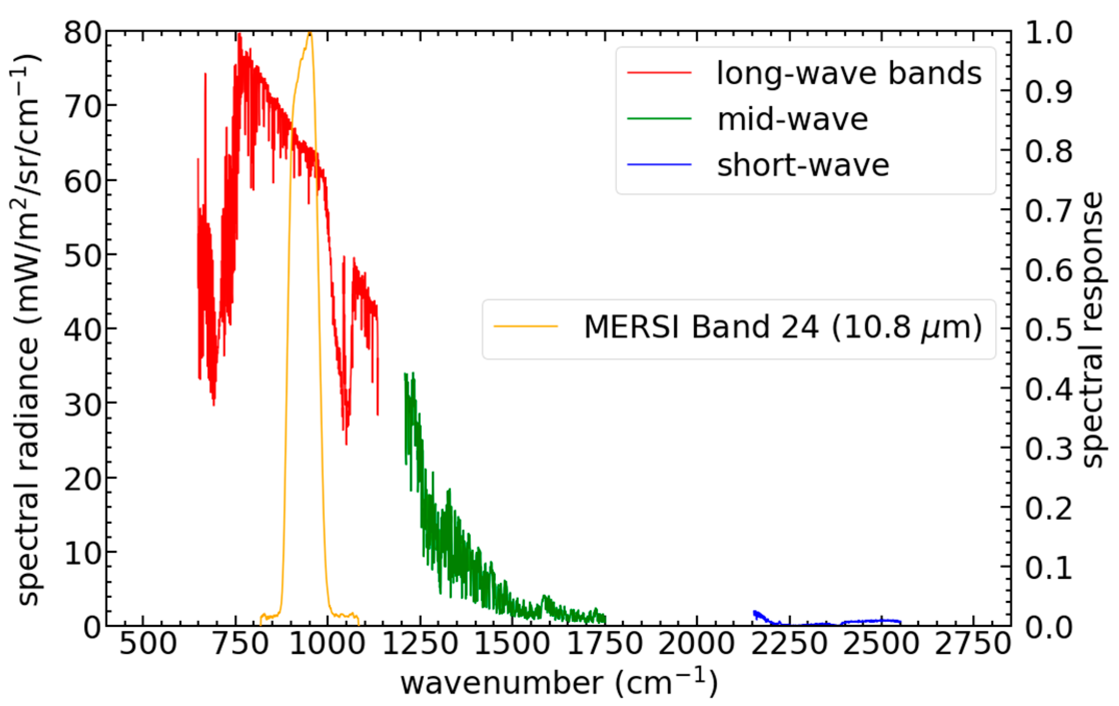
The High-Spectral InfraRed Atmospheric Sounder (HIRAS) is a space-borne Fourier transform spectrometer (FTS) onboard the FY-3D, launched into an afternoon orbit on 15 November 2017. It is the first infrared (IR) FTS onboard the satellite in the Chinese polar-orbiting FY-3 series and is a major step forward in the Chinese operational IR sounding capability previously provided by the broadband InfraRed Atmospheric Sounder (IRAS) onboard the first three satellites of the FY-3 series. HIRAS will be a standard payload on the following satellites in the FY-3 series. The FY-3D/HIRAS provides radiance spectra measurements of 2275 channels in three spectral bands: the long-wave (LW) IR band from 650 to 1135 cm−1, the mid-wave (MW) IR band from 1210 to 1750 cm−1, and the short-wave (SW) IR band from 2155 to 2550 cm−1, with a spectral resolution of 0.625 cm−1 for all the three bands, which are shown in Table 2. The FY-3D/HIRAS has a spatial resolution of 16 km.
Overall, the FY-3D/HIRAS instrument has a range of parameters that enable it to collect detailed and accurate data about the Earth’s surface and atmosphere, which can be used for a variety of scientific and practical applications.
In order to verify the reliability of the uncertainty assessment model of the SNO cross-calibration method for satellite IR channels proposed in Section 2.2 of this paper, FY-3D/HIRAS is used as the reference instrument and FY-3D/MERSI is used as the instrument to be calibrated. Using the loading parameters of these two instruments, such as the spatial resolution, spectral resolution, and the parameter of PSF, a dedicated dataset is constructed for assessing the uncertainty of the SNO cross-calibration method itself. Specifically, FY-3D/MERSI Band 24 (10.8 μm) was selected as the simulated channel in this study (Figure 3).

3.2. Model

Assessing the uncertainty of SNO cross-calibration results involves considering various factors, such as the measurement noise in the monitored instrument, calibration uncertainty in the reference instrument, data matching errors, and regression analysis uncertainty. In an ideal scenario, the matching data between the reference remote sensor and the remote sensor being calibrated should be identical when observing the same target under the same time and line-of-sight geometric conditions. However, in reality, discrepancies arise due to factors such as instrument optical parameters (e.g., PSF), instrument noise, and the inherent mismatch in the SNO cross-calibration process.
To address this, the data simulation model developed in this study comprises two parts. The first part utilizes measured data from the reference remote sensor, which is then simulated and constructed into the simulated data for the remote sensor being calibrated. To better capture the actual conditions, the PSF is introduced. The PSF weight matrix is used to generate multiple high-spatial-resolution image radiation values from low-spatial-resolution image radiation values within the same image field of view.
In the context of the SNO cross-calibration method, the PSF plays a crucial role in simulating and understanding the uncertainties associated with the matching of observed data between the reference and monitored instruments.
The PSF describes the response of the imaging system to a point source or object. The PSF effect causes the radiant power from the point target to become scattered in the surrounding single-element detectors rather than concentrated in one single-element detector [30,31]. It represents the spatial distribution of light intensity that results from diffraction, aberrations, and other factors in the system.
Mathematically, the PSF is a function that maps a point source, ideally represented as a mathematical point, to an intensity distribution on the image plane. It characterizes the blurring or spreading of the point source over neighboring pixels or areas in the image. Based on the two-dimensional Gaussian function, the weight matrix of the PSF of the instrument was constructed:
h x , y = 1 2 π σ 2 e x p x 2 + y 2 2 σ 2
Here, σ is the standard deviation, i.e., the width of the control function.
In the context of remote sensing and image analysis, understanding and accounting for the PSF is crucial for accurate interpretation, calibration, and deconvolution of images. It allows for the correction of spatial distortions and helps quantify the uncertainties introduced by the imaging system in capturing and representing the observed scene.
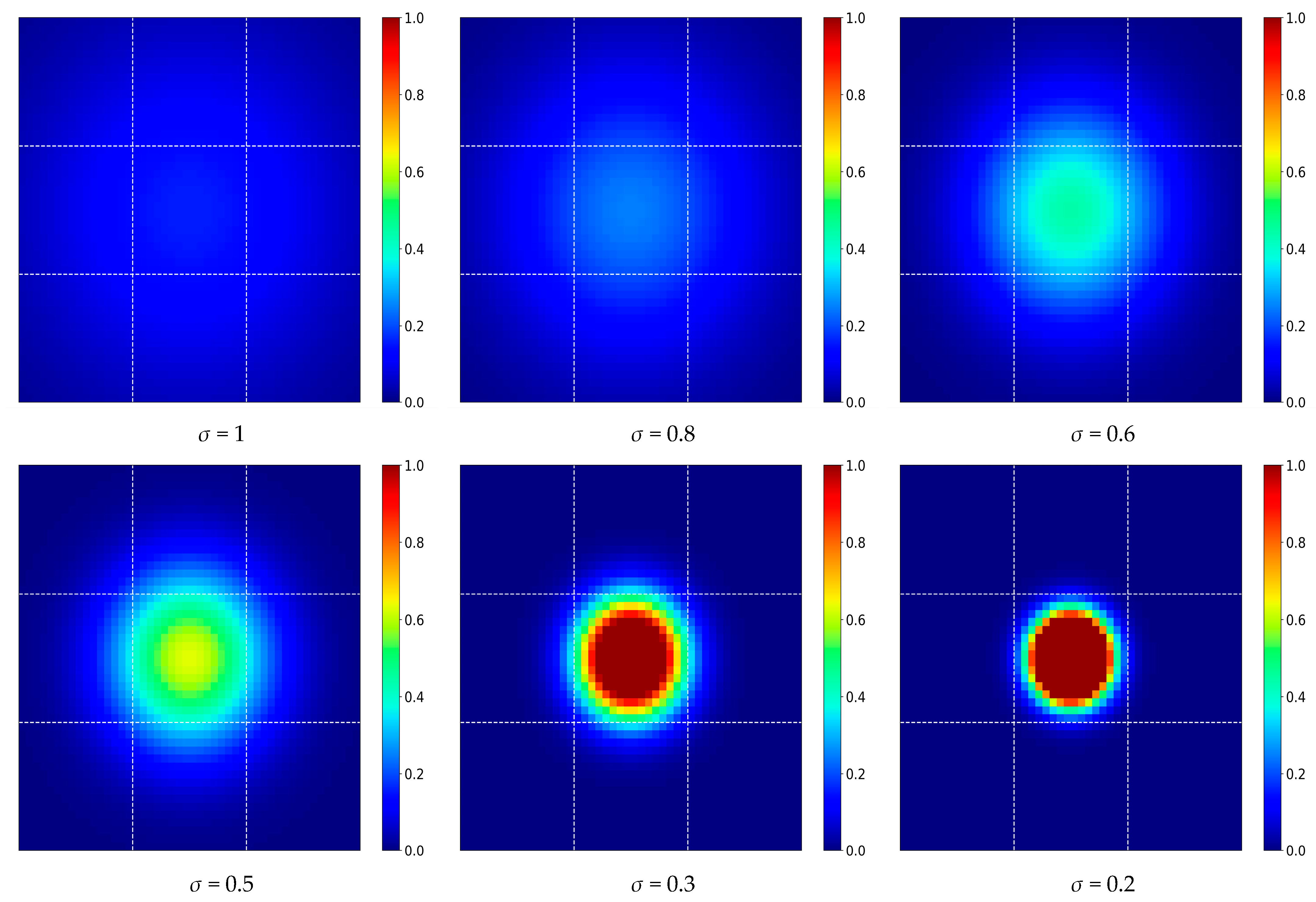
Normally, a diffuse spot will cover a 3 × 3 detection cell, and in the same way, a received detection cell; the received radiation value is the weighted sum of the data of the cell corresponding to the target and its surrounding 3 × 3 [20]. The different σ makes the weight of each pixel point different, and the weight of its center pixel is 20%, 25%, 36%, 47%, 82%, and 97.5% when σ = 1, 0.8, 0.6, 0.5, 0.3, and 0.2, respectively. The situation is shown in Figure 4.
To construct the PSF of the instrument, it is crucial to understand the influence of each pixel and its surrounding pixels on the target data collected by the instrument. Typically, the collected data are affected by the pixels within a 3 × 3 range around the target. By determining the weight at the corresponding point of each pixel, the radiation value of each pixel is multiplied by its weight and summed, resulting in the final instrument-collected data.
The weight matrix of the PSF is derived by assuming that each pixel is solely influenced by the 3 × 3 pixels centered on it. The σ parameter of the PSF, which represents the width of the control function, corresponds to different values of the satellite modulation transfer function at the Nyquist frequency (MTF0.5). These correspondences are presented in Table 3.
In this paper, σ = 0.36 (MTF0.5 = 0.3) is used as an example for analysis. Its weight matrix is as follows.
A = 0.00679312 0.06883413 0.00679312 0.06883413 0.69749101 0.06883413 0.00679312 0.06883413 0.00679312
The second part involves randomly incorporating errors introduced by each step of the SNO cross-calibration process into the constructed matching dataset from the previous step. This accounts for the uncertainties arising from the calibration process. By considering these factors and employing the data simulation model, comprehensive assessment of the uncertainty in SNO cross-calibration can be achieved.
In order to closely align the constructed data with the telemetry data, a simulation model is employed to generate matching data for both the reference instrument and the monitored instrument. This simulation takes into account the resolutions of the instruments, the parameters of the PSF (with a value of 0.36 for FY-3D/MERSI), the angle of observation, and the spatial uniformity. By considering these factors, the simulation model aims to generate data that closely resemble the actual observations made by the instruments.
The SNO cross-calibration process involves using matching point data, which includes both target area data and background area data. The size of these data sets is determined by the sub-satellite resolution of the satellite instruments. For HIRAS, the sub-satellite resolution is 16 km, while for MERSI Band 24 (10.8 μm), it is 250 m. To ensure uniformity in the background observations, the uniformity of the background area is tested. The background should meet certain conditions as described by Equation (16) in order to obtain consistent and reliable observations.
RSTD ENV = STD ENV / MEAN ENV < δ RSTD
For all pixel radiances observed by the monitored instrument in the environmental area (referred to as ENV), several statistical measures are considered. RSTDENV represents the relative standard deviation, STDENV represents the standard deviation of all pixel radiances, MEANENV represents the average value of all pixel radiances, and δRSTD represents the threshold for spatial uniformity. These measures provide insights into the variability, spread, and average of the pixel radiances within the environmental area, while the threshold δRSTD helps determine the level of acceptable spatial uniformity.
Because the half field of view of the ground target relative to the satellite detection system is significantly smaller than the instantaneous field of view of the detection system itself, the ground target can be treated as a point target during the simulation of satellite observation data, using the detection system as the reference plane.
As a result, multiple pairs of matched radiance data were obtained, and each pair was assigned a random error value that accounts for temporal differences, spatial differences, and angular differences with respect to the calibration results. Additionally, this study incorporates the convolution method to consider the radiance transfer from the IR hyperspectral instrument (reference instrument) to the channel spectrum of the instrument being calibrated.
In the SNO cross-calibration process, this study establishes thresholds for the matching parameters, which are provided in Table 4. These threshold parameters are based on references from previous studies [24,32,33].

4. Sensitivity Analysis of Error Propagation

Using the simulation model and the parameter thresholds specified in Table 1, we generated simulation data to assess the uncertainty associated with calibration results. This uncertainty arises from data matching and data regression, which can be quantified using the uncertainty assessment equations of the SNO cross-calibration method discussed in Section 3. The uncertainty analysis of data matching focused on temporal matching, spatial matching, angular matching, and spectral matching. A crucial aspect of this analysis involved conducting sensitivity analysis to evaluate the impact of these four factors on the overall uncertainty assessment. Consequently, we calculated the sensitivity coefficient of the uncertainty in sample radiation values for each factor.

4.1. Sensitivity to Temporal Matching

The temporal matching of observations between the reference and monitored instruments is not always perfect, resulting in a time gap. This time gap introduces variations in the atmosphere, clouds, and ground surface, which can impact the matched data. In this study, we utilized Himawari-8 geostationary satellite data to calculate the sensitivity coefficient (∂Ltarget/t) in Equation (2). Himawari-8’s regional observation mode with a short interval of 2.5 min allowed for a more detailed analysis of the variation in target radiance over time [34]. We specifically focused on the 10.4 μm channel of Himawari-8, which is similar to MERSI Band 24 (10.8 μm), and analyzed it using different spatial uniformity thresholds and time difference thresholds (Δt). The obtained ∂Ltarget/t values (unit: mW/m2/sr/cm−1/s) for the 10.4 μm channel under varying thresholds are presented in Table 5.
However, it should be acknowledged that the temporal sensitivity analysis using actual data may contain noise from the analyzed instrument itself, which could influence the accuracy of the results to some extent. Nevertheless, due to the low noise level of the instrument itself, the impact is considered to be limited.

4.2. Sensitivity to Spatial Matching

In spatial matching, the selection of the target area for observation is typically based on the spatial resolution relationship, with priority given to the area where the target instrument is closest to the reference instrument. However, in practical situations, there can be a certain positioning deviation of the pixel, which can introduce changes in the calibration results. To analyze the effect of positioning deviation, a simulation data set was constructed, and the variation of the target pixel radiance with respect to positioning deviation was examined under different positioning deviation thresholds (Δd) and spatial uniformity thresholds (δRSTD). The sensitivity coefficient (∂Ltarget/d) was calculated in mW/m²/sr/cm−1/km. The results for different Δd values of 1, 2, 3, and 4 km are presented in Table 6.

4.3. Sensitivity to the Zenith Angle Threshold of Satellite Observations

Deviations in the zenith angle of satellite observations can cause the matched data to deviate from the ideal value. In this study, the MODTRAN radiative transfer model was used to simulate the variation of target pixel radiance with respect to the angular matching error at different angular deviations, i.e., the sensitivity coefficient ∂Ltarget/∂θ with mW/m²/sr/cm−1/° as the unit. This part of the analysis is based on setting the true value of the satellite zenith angle to 30°. Statistical analysis was conducted with the spatial uniformity threshold δRSTD being 0.05, as there was no correlation between the spatial uniformity and the zenith angle of the satellite observations. The angle deviations were set to 1°, 2°, and 3° for three scenarios, corresponding to the angular matching error thresholds of 0.01, 0.02, and 0.03, respectively. The results are shown in Table 7. Hewison (2013) [21] also evaluated the uncertainty of the SNO cross-calibration results. The uncertainty caused by the spectra in them is also small and is consistent with the results of this paper.

4.4. Sensitivity to Instrument Spectral Matching

We considered the radiance from the IR hyperspectral (reference instrument) to the channel spectrum (instrument to be calibrated) by a convolution method. By convoluting the hyperspectral data with the channel spectrum, we can accurately establish the consistency of the channel spectral response. The spectral convolution equation is as follows:
L 2 = λ 1 λ 2 L 1 ( λ ) f ( λ ) d λ λ 1 λ 2 f ( λ ) d λ
where L1 is the radiance observed by the reference hyperspectral remote instrument, L2 is the radiance of the channel after integrating the channel spectral response function of the instrument to be calibrated, f is the spectral response function of the corresponding channel of the instrument to be calibrated, and 1, 2 represent the upper and lower limits of the spectral response range of the instrument to be calibrated, respectively.
One of the uncertainties associated with the SNO cross-calibration method is the spectrum drift (or spectral calibration) of the hyperspectral instrument. In this paper, we only consider the spectral drift of the hyperspectral instrument, as the channel relative spectral responses can be accurately measured.
The condition for spectral matching is expressed by the spectral drift threshold Δν/ν, which represents the relative deviation of the spectrum. In line with the previous subsection, statistical analysis was performed with a spatial uniformity threshold δRSTD of 0.05. The sensitivity coefficients of the radiance to the spectral drift thresholds were calculated by comparing the radiances obtained from the convolution before and after the spectral drift in three scenarios: 3, 4, and 5 ppm. The results are presented in Table 8.

5. Uncertainty Assessment of SNO Cross-Calibration

5.1. Standard Uncertainties Caused by Factors in Sample Matching

Using the sensitivity coefficients obtained from the previous section, the standard uncertainty caused by each factor can be calculated, leading to the determination of the uncertainty in the calibration results resulting from sample matching. The spatial uniformity threshold for the environmental area was set to 0.05 for these calculations.
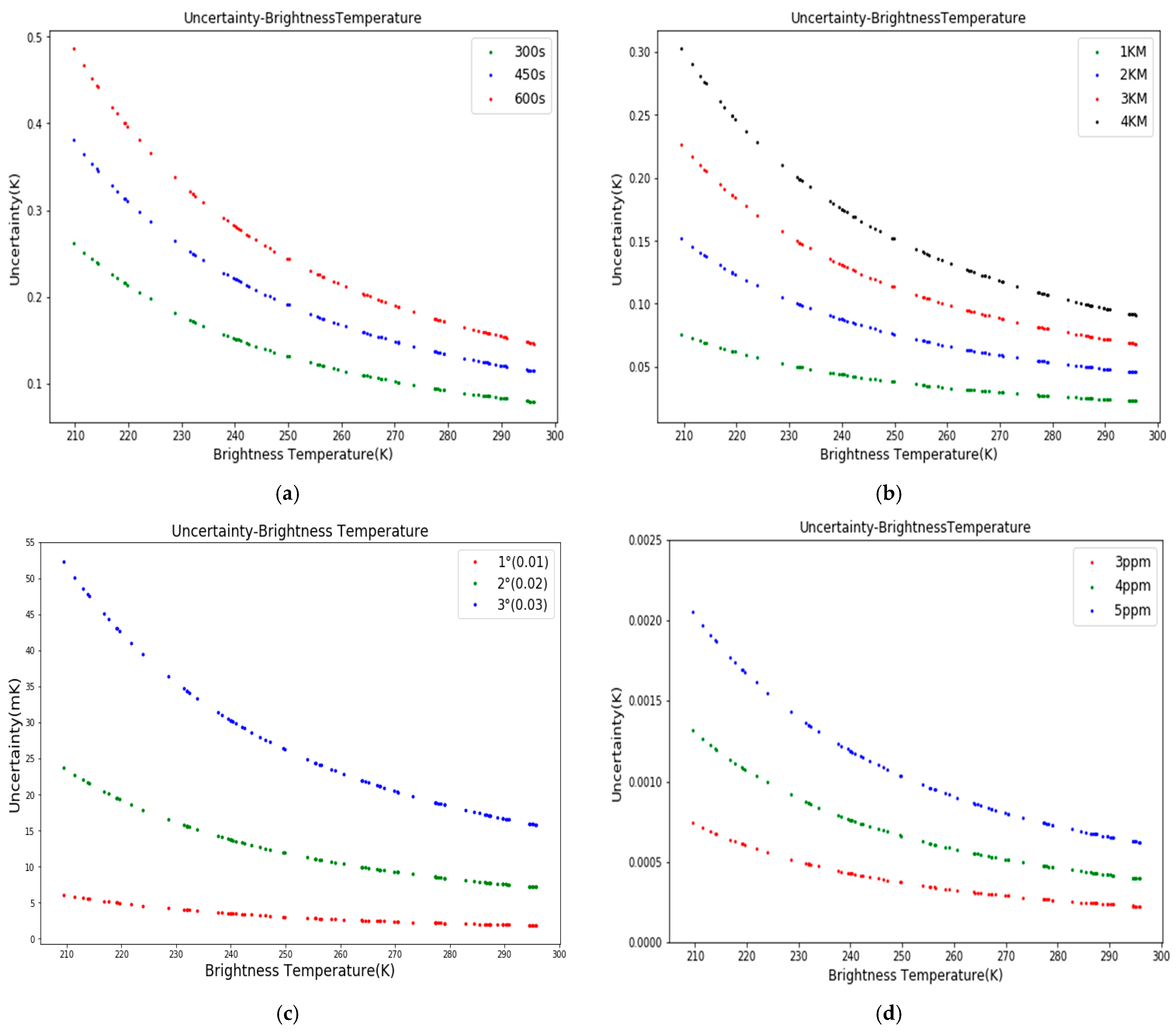
For different configurations of temporal matching, spatial matching, angular matching, and spectral matching, the standard uncertainties of brightness temperature were calculated for each of these four factors using Equation (2). Figure 5 illustrates that the standard uncertainty associated with each factor decreases as the brightness temperature increases. This trend can be attributed to the fact that, according to the derivative of the Planck equation, the same radiance variation produces less brightness temperature variation at higher brightness temperatures.
To analyze the variations in uncertainties of the calibration results due to sample matching in the SNO cross-calibration across different brightness temperatures, three representative brightness temperatures of 210 K, 280 K, and 300 K were selected to represent low, medium, and high brightness temperature environments, respectively. The results are presented in Table 9.
When the temporal matching threshold Δt was set to 450 s, the uncertainty of the calibration results reached 0.39 K at a low brightness temperature of 210 K, 0.13 K at a medium brightness temperature of 280 K, and 0.12 K at a high brightness temperature of 300 K. The threshold value can be adjusted if the required accuracy is not satisfied. For example, if Δt was set to 300 s, the uncertainties at the three typical brightness temperatures were 0.26 K, 0.08 K, and 0.05 K, respectively.
When the positioning deviation threshold Δd was set to 1 km, the uncertainty was 0.08 K at a low brightness temperature, approximately 0.025 K at a medium brightness temperature, and approximately 0.02 K at a high brightness temperature. However, when Δd was set to 3 km, the corresponding uncertainties were 0.23, 0.08, and 0.07 K, respectively.
When the zenith angle deviation threshold Δθ was set to 0.01, the uncertainty was approximately 6.0 × 10⁻³ K at a low brightness temperature, 2.0 × 10⁻³ K at a medium brightness temperature, and 1.5 × 10⁻³ K at a high brightness temperature. If Δθ was set to 0.03, the uncertainties were 5.3 × 10⁻², 1.9 × 10⁻², and 1.7 × 10⁻² K, respectively.
When the spectral drift threshold Δν was set to 3 ppm, the uncertainty at a low brightness temperature was only 7 × 10⁻⁴ K. As Δν increased, the uncertainty at a low temperature increased, which exceeded 2.0 × 10⁻³ K when Δν was set to 5 ppm.

5.2. Combined Uncertainty of Calibration Results

In the previous section, we analyzed the standard uncertainties resulting from different matching thresholds for sample matching. However, the fitting method used in regression analysis also introduces some uncertainty to the calibration results. To consider this combined uncertainty, the total uncertainty of the calibration results (with a coverage factor of k = 1) was calculated using Equation (11), taking into account the standard uncertainties from sample matching and the fitting parameters (slope and intercept). Table 10 presents the combined uncertainties for typical brightness temperatures under the SNO cross-calibration standard conditions. These conditions include a temporal matching threshold of 300 s, a positioning deviation threshold of 3 km, an observation geometry matching threshold of 0.01, a spectral drift threshold of 3 ppm, and a spatial uniformity threshold of 0.05.

6. Discussion

In order to address the uncertainty associated with the widely used SNO cross-calibration method for satellite infrared channels, this study conducted an analysis of the main factors influencing the cross-calibration. Theoretical equations were derived to assess the uncertainty, and simulation data were generated by considering the PSF parameters, instrument spatial resolution, and spatial uniformity. The sensitivities of target radiance to temporal matching, spatial matching, angular matching, and spectral drift were investigated. Additionally, errors in the fitting method for sample points were taken into account. As a result, a set of generalized models and methods applicable to the uncertainty assessment of commonly used meteorological satellite remote sensing instruments using the SNO cross-calibration method were developed.
Based on the parameters of FY-3D/HIRAS and FY-3D/MERSI instruments and the standard SNO cross-calibration thresholds, this study employed the standard SNO cross-calibration method as a reference. The spatial uniformity threshold was set to 0.05, and the PSF standard deviation was set to 0.36. The thresholds used were as follows: a temporal matching threshold of 300 s, a positioning deviation threshold of 3 km, an observation geometry matching threshold of 1°, and a spectral drift threshold of 3 ppm.
Considering only the error in temporal matching, the theoretical calibration uncertainties caused by the temporal matching threshold of 300 s in the standard SNO cross-calibration were found to be 0.26 K, 0.08 K, and 0.05 K for low, medium, and high brightness temperatures, respectively. Furthermore, the uncertainties resulting from the spatial matching threshold of 3 km were similar to those caused by the temporal matching threshold of 300 s, amounting to 0.23 K, 0.08 K, and 0.07 K, respectively. The uncertainties introduced by angular differences and spectral drift were on the order of millikelvins (mK), significantly smaller than those caused by temporal and spatial differences. The combined uncertainties (k = 1) calculated for the three typical brightness temperatures were 0.38548 K, 0.14456 K, and 0.10012 K.
Table 11 presents the results of cross-calibration uncertainty from different studies. Both this study and the work by Hewison (2013) [24] provide uncertainty values at any given brightness temperature for different channel SNO cross-calibration uncertainties. On the other hand, other studies [35] can only offer uncertainty ranges for specific channels. Assessing the uncertainty of SNO cross-calibration in the infrared channel can be accomplished using both actual and simulated data as the two main approaches.
The total uncertainty of the calibration results is mainly assessed by analyzing the actual observation data from two specific satellites during the calibration process. However, this analysis of actual satellite observations includes measurement noise from the monitored instrument, calibration uncertainties from the reference instrument, data matching errors, and uncertainty in regression analysis. Using actual data to assess the SNO cross-calibration uncertainty of satellite IR channels has some shortcomings, which are as follows:
(1)
Lack of representative data: the amount of data available may not be enough or may not be representative of all possible atmospheric conditions and surface types;
(2)
Instrument noise: the instruments used to collect the data may add noise or bias to the measurements, which can affect the accuracy of the calibration.
It is important to consider these shortcomings and account for them when assessing the uncertainty of SNO cross-calibration using actual data. Taking appropriate measures to address these issues can help improve the reliability and accuracy of the calibration results.
The SNO cross-calibration matching data are generated by simulating various parameters such as the two-dimensional PSF, instrument spatial resolution, and spatial uniformity. The study investigates the sensitivities of target radiance to factors such as temporal matching, spatial matching, angular matching, and spectral drift. Additionally, errors arising from the fitting method for sample points are taken into account. Through these analyses, a generalized model is developed to assess the uncertainty associated with the SNO cross-calibration method for meteorological satellite infrared channels.

7. Conclusions

This method enables the establishment of generalized models for assessing the uncertainty of the SNO cross-calibration method itself in satellite infrared channels, specifically in the forward direction. Furthermore, it offers valuable guidance for selecting appropriate temporal and spatial matching thresholds, ensuring environmental uniformity, and optimizing the parameters of reference instruments to achieve the desired radiometric calibration accuracy in the SNO cross-calibration method.
In addition, it is important to further investigate the factors that contribute to systematic errors in the SNO cross-calibration. This includes exploring systematic errors in the observation noises of satellite remote sensors and the calibration accuracy of the reference instruments. Regarding spectral matching, it is essential to consider the errors introduced by channel-to-channel spectral matching, which is widely used in the SNO cross-calibration of high-resolution satellites.
The satellite cross-calibration method holds significant importance in climate studies, particularly in capturing long-term observations of subtle changes in the Earth’s atmosphere, oceans, and land surface. By identifying and mitigating instrumental biases and uncertainties, it plays a vital role in enhancing the accuracy and reliability of climate data.
It is worth noting in this article that actual data are used in the analysis of temporal and spatial sensitivity analysis, and the analysis results may also contain noise from the analyzed instrument itself, which may influence the accuracy of the sensitivity analysis results to some extent. But this effect is limited because the noise level of the instrument itself is not large.
At this stage, this study is has been completed on the time, space, and spectral drift calibration results. The impact analysis will be carried out in the following areas.
(1)
Analysis of more remote sensing data to obtain a realistic situation;
(2)
Further analysis of the influencing factors such as observation geometry conditions and spectral corrections to improve the links;
(3)
Combination of the theoretical results with the actual remote sensing data to confirm the applicability of the method and make a correlation.
According to the Chinese Space-Based Radiometric Benchmarks program that started in 2014, a radiometric reference satellite is expected to be launched in 2025, which can act as a reference radiometric benchmark for other satellite instruments to improve the accuracy of space-based climate observations globally [36]. This method can also serve as a valuable reference for demonstrating Chinese space-based radiometric benchmark indexes and their transfer to radiometric cross-calibration. It offers insights into the process of establishing benchmark indexes and provides guidance on how to effectively apply them in radiometric cross-calibration procedures. By leveraging this method, Chinese space-based radiometric benchmark indexes can be utilized as reliable standards for ensuring the accuracy and consistency of radiometric measurements in various satellite missions.
Furthermore, this study provides reliable basic data support for climate application work. The satellite cross-calibration method holds great importance for climate studies, as they require long-term observations to detect subtle changes in the Earth’s atmosphere, oceans, and land surface. It plays a crucial role in identifying and reducing instrumental biases and uncertainties, thereby enhancing the accuracy and reliability of the collected data.
The findings of this study significantly contribute to strengthening the scientific and technical support for satellite observations in global climate change studies. The assessment of SNO cross-calibration uncertainty is instrumental in establishing a consistent and reliable long-term climate data record across multiple satellite sensors. Accurately quantifying this uncertainty is essential for evaluating the dependability of climate data products and comprehending their impact on climate research and decision-making processes.

Author Contributions

Conceptualization, L.C. and P.Z.; methodology, L.C., Z.G. and H.D.; validation, Z.G. and H.D.; formal analysis, Z.G. and H.D.; investigation, L.C., Z.G. and H.D.; writing—original draft preparation, Z.G., L.C. and L.T.; writing—review and editing, L.C., Z.G., L.T. and P.Z.; visualization, Z.G. and H.D.; supervision, L.C. and P.Z.; project administration, L.C., P.Z. and X.H.; funding acquisition, L.C. All authors have read and agreed to the published version of the manuscript.

Funding

This research was funded by the National Key Research and Development Program of China (Grant Nos. 2018YFB0504900, 2018YFB0504905) and National Natural Science Foundation of China (Grant Nos. 41675036).

Data Availability Statement

The data that support the findings of this study are available from the corresponding authors upon reasonable request.

Acknowledgments

The authors would like to thank the following for their support: FY-3D/HIRAS L1 data from National Satellite meteorological Center of China (NSMC), Himawari-8/AHI L1 data from Japan Meteorological Agency (JMA) and the MODTRAN model.

Conflicts of Interest

The authors declare no conflict of interest.

References

  1. Bouvet, M.; Thome, K.; Berthelot, B.; Bialek, A.; Czapla-Myers, J.; Fox, N.P.; Goryl, P.; Henry, P.; Ma, L.; Marcq, S. RadCalNet: A radiometric calibration network for Earth observing imagers operating in the visible to shortwave infrared spectral range. Remote Sens. 2019, 11, 2401. [Google Scholar] [CrossRef] [Green Version]
  2. Okuyama, A.; Takahashi, M.; Date, K.; Hosaka, K.; Murata, H.; Tabata, T.; Yoshino, R. Validation of Himawari- 8/AHI radiometric calibration based on two years of in-orbit data. J. Meteorol. Soc. Jpn. Ser II 2018, 96, 91–109. [Google Scholar] [CrossRef] [Green Version]
  3. Liu, Y.; Ma, L.; Zhao, Y.; Wang, N.; Qian, Y.; Li, W.; Gao, C.; Qiu, S.; Li, C. A spectrum extension approach for radiometric calibration of the advanced hyperspectral imager aboard the Gaofen-5 Satellite. IEEE Trans. Geosci. Remote Sens. 2021, 60, 1–10. [Google Scholar] [CrossRef]
  4. Yan, L.; Hu, Y.; Zhang, Y.; Li, X.-M.; Dou, C.; Li, J.; Si, Y.; Zhang, L. Radiometric Calibration Evaluation for FY3D MERSI-II Thermal Infrared Channels at Lake Qinghai. Remote Sens. 2021, 13, 466. [Google Scholar] [CrossRef]
  5. Rong, Z.; Zhang, Y.; Lu, F.; Xu, J.; Qiu, K. Inter-calibration of FY-2B IR channel with NOAA satellites. Acta Meteorol. Sin. 2005, 63, 485–492. [Google Scholar]
  6. Cao, C.; Uprety, S.; Blonski, S. Establishing radiometric consistency among VIIRS, MODIS, and AVHRR using SNO and SNOx methods. In Proceedings of the 2012 IEEE International Geoscience and Remote Sensing Symposium, Munich, Germany, 22–27 July 2012; pp. 6928–6931. [Google Scholar]
  7. Biggar, S.F.; Slater, P.N.; Gellman, D.I. Uncertainties in the in-flight calibration of sensors with reference to measured ground sites in the 0.4-1.1 μm range. Remote Sens. Environ. 1994, 48, 245–252. [Google Scholar] [CrossRef]
  8. Dinguirard, M.; Slater, P.N. Calibration of space-multispectral imaging sensors: A review. Remote Sens. Environ. 1999, 68, 194–205. [Google Scholar] [CrossRef]
  9. Cao, C.; Weng, F.; Goldberg, M.; Wu, X.; Xu, H.; Ciren, P. Intersatellite calibration of Polar-orbiting radiometers using the SNO/SCO method. In Proceedings of the IEEE International Geoscience and Remote Sensing Symposium, Seoul, Republic of Korea, 29 July 2005; pp. 109–112. [Google Scholar]
  10. Chander, G.; Hewison, T.J.; Fox, N.; Wu, X.; Xiong, X.; Blackwell, W.J. Overview of Intercalibration of Satellite Instruments. IEEE Trans. Geosci. Remote Sens. 2013, 51, 1056–1080. [Google Scholar] [CrossRef]
  11. Tobin, D.; Holz, R.; Nagle, F.; Revercomb, H. Characterization of the Climate Absolute Radiance and Refractivity Observatory (CLARREO) ability to serve as an infrared satellite intercalibration reference. J. Geophys. Res. Atmos. 2016, 121, 4258–4271. [Google Scholar] [CrossRef] [Green Version]
  12. Guo, Q.; Chen, B.-Y.; Zhang, Y.; Xu, N.; Feng, X.; Yang, C.J.; Wang, X.; Han, X.Z.; Li, Y.; Hu, X.Q. Progress in on-orbit radiometric calibration technology for Fengyun-2 satellite. Adv. Meteorol. Sci. Technol. 2013, 3, 6–12. [Google Scholar]
  13. Zhang, Z.; Zhang, H.; Chang, Y.; Chen, Z.C. Review of radiometric calibration methods of Landsat series optical remote sensors. J. Remote Sens. 2015, 19, 719. [Google Scholar]
  14. Jin, C.; Choi, C. The Assessment of Cross Calibration/Validation Accuracy for KOMPSAT-3 Using Landsat 8 and 6S. Korean J. Remote Sens. 2021, 37, 123–137. [Google Scholar]
  15. Xu, N.; Hu, X.-Q.; Chen, L.; Zhang, Y.-X. Cross-calibration of FY-2 E/VISSR infrared window and water vapor channels with TERRA/MODIS. J. Infrared Millim. Waves. 2012, 31, 319–324. [Google Scholar] [CrossRef]
  16. Xu, N.; Hu, X.; Chen, L.; Min, M. Inter-calibration of infrared channels of FY-2/VISSR using high-spectral resolution sensors IASI and AIRS. Yaogan Xuebao-J. Remote Sens. 2012, 16, 939–952. [Google Scholar]
  17. Zhang, P.; Lu, Q.; Hu, X.; Gu, S.; Yang, L.; Min, M.; Chen, L.; Xu, N.; Sun, L.; Bai, W. Latest progress of the Chinese meteorological satellite program and core data processing technologies. Adv. Atmos. Sci. 2019, 36, 1027–1045. [Google Scholar] [CrossRef]
  18. Xu, L.; Ma, L.; Hu, J.; Tang, L. Cross-calibration of HJ-1B/CCD1 against Terra/MODIS. Remote Sens. Inf. 2011, 2, 26–31. [Google Scholar]
  19. Zhang, Y.-H.; Mao, H.-Q.; Wang, Z.-T.; Guo, W.; Li, Q.; Li, Z.-Q.; Chen, X.-F.; Chen, H. Cross Calibration Between GOCI and MODIS Based on Spectral and Geometry Matching. J. Atmos. Environ. Opt. 2016, 11, 412–422. [Google Scholar]
  20. Wang, Z.; Xiao, P.; Gu, X.; Feng, X.; Li, X.; Gao, H.; Li, H.; Lin, J.; Zhang, X. Uncertainty analysis of cross-calibration for HJ-1 CCD camera. Sci. China Technol. Sci. 2013, 56, 713–723. [Google Scholar] [CrossRef]
  21. Chen, Z.; Zhang, B.; Zhang, H.; Zhang, W. Vicarious calibration of Beijing-1 multispectral imagers. Remote Sens. 2014, 6, 1432–1450. [Google Scholar] [CrossRef] [Green Version]
  22. Bhatt, R.; Doelling, D.; Haney, C.; Scarino, B.; Gopalan, A. Consideration of radiometric quantization error in satellite sensor cross-calibration. Remote Sens. 2018, 10, 1131. [Google Scholar] [CrossRef] [Green Version]
  23. Datla, R.V.; Kessel, R.; Smith, A.W.; Kacker, R.N.; Pollock, D.B. Uncertainty analysis of remote sensing optical sensor data: Guiding principles to achieve metrological consistency. Int. J. Remote Sens. 2010, 31, 867–880. [Google Scholar] [CrossRef]
  24. Hewison, T.J. An evaluation of the uncertainty of the GSICS SEVIRI-IASI intercalibration products. IEEE Trans. Geosci. Remote Sens. 2013, 51, 1171–1181. [Google Scholar] [CrossRef]
  25. Joint Committee for Guides in Metrology. Evaluation of measurement data—Guide to the expression of uncertainty in measurement. JCGM 2008, 100, 1–116. [Google Scholar]
  26. Xu, N.; Hu, X.; Chen, L.; Zhang, Y.; Hu, J.; Sun, L. On-orbit radiometric calibration accuracy of FY-3A MERSI thermal infrared channel. Spectrosc. Spectr. Anal. 2014, 34, 3429–3434. [Google Scholar]
  27. Zhao, W.; Hu, X.; Fang, W. Development and applications of intercalibration for satellite optical instruments. Opt. Precis. Eng. 2015, 23, 1921–1931. [Google Scholar] [CrossRef]
  28. Damasceno, J.C.; Couto, P.R. Methods for evaluation of measurement uncertainty. In Metrology; IntechOpen: London, UK, 2018; pp. 9–28. [Google Scholar]
  29. ISO/TS 28037; Determination and Use of Straight-Line Calibration Functions. International Organization for Standardization: Geneva, Switzerland, 2010.
  30. Zhang, Z.Y.; Peng, Q.Y. Comparison of fitting ePSF and fitting Gaussian-functions. Astron. Res. Technol. 2010, 7, 132–139. [Google Scholar]
  31. Mahalanobis, A.; Shilling, R.; Murphy, R.; Muise, R. Recent results of medium wave infrared compressive sensing. Appl. Opt. 2014, 53, 8060–8070. [Google Scholar] [CrossRef]
  32. Cao, C.; Weinreb, M.; Xu, H. Predicting simultaneous nadir overpasses among polar-orbiting meteorological satellites for the intersatellite calibration of radiometers. J. Atmos. Ocean. Technol. 2004, 21, 537–542. [Google Scholar] [CrossRef]
  33. Wu, X.; Hewison, T.; Tahara, Y. GSICS GEO-LEO intercalibration: Baseline algorithm and early results. In Proceedings of the Atmospheric and Environmental Remote Sensing Data Processing and Utilization V: Readiness for GEOSS III, San Diego, CA, USA, 2–6 August 2009; SPIE: Bellingham, WA, USA, 2009; Volume 7456, pp. 25–36. [Google Scholar]
  34. Bessho, K.; Date, K.; Hayashi, M.; Ikeda, A.; Yoshida, R. An Introduction to Himawari-8/9 — Japan’s New-Generation Geostationary Meteorological Satellites. J. Meteorol. Soc. Jpn. 2016, 94, 151–183. [Google Scholar] [CrossRef] [Green Version]
  35. Kim, D.; Gu, M.; Oh, T.H.; Kim, E.K.; Yang, H.J. Introduction of the Advanced Meteorological Imager of Geo-Kompsat-2a: In-orbit tests and performance validation. Remote Sens. 2021, 13, 1303. [Google Scholar] [CrossRef]
  36. Zhang, P.; Lu, N.; Li, C.; Ding, L.; Zheng, X.; Zhang, X.; Hu, X.; Ye, X.; Ma, L.; Xu, N. Development of the Chinese space-based radiometric benchmark mission LIBRA. Remote Sens. 2020, 12, 2179. [Google Scholar] [CrossRef]
Figure 1. The Simultaneous Nadir Observation (SNO) cross-calibration process.
Remotesensing 15 03313 g001
Figure 2. The flow chart of SNO cross-calibration uncertainty propagation.
Remotesensing 15 03313 g002
Figure 3. The measured spectral radiance of FY-3D/HIRAS (short-wave, mid-wave, and long-wave bands are shown using different colors) and the spectral response of FY-3D/MERSI Band 24 (10.8 μm).
Remotesensing 15 03313 g003
Figure 4. The different values of σ make the weight of each pixel point different, and the weight of its center pixel is 20%, 25%, 36%, 47%, 82%, and 97.5% when σ = 1, 0.8, 0.6, 0.5, 0.3, and 0.2, respectively.
Remotesensing 15 03313 g004
Figure 5. Standard uncertainties of the matched sample brightness temperature introduced by different configurations of (a) temporal matching, (b) spatial matching, (c) angular matching, and (d) spectral matching under the spatial uniformity threshold of 0.05.
Remotesensing 15 03313 g005
Table 1. The wavelengths of the FY-3D/MERSI-II instrument.
BandCenter Wavelength (µm)Width (nm)Spatial Resolution (m)
10.47050250
20.55050250
30.65050250
40.86550250
51.38020/301000
61.640501000
72.130501000
80.412201000
90.443201000
100.490201000
110.555201000
120.670201000
130.709201000
140.749201000
150.865201000
160.905201000
170.936201000
180.940501000
191.030201000
203.8001801000
214.0501551000
227.2005001000
238.5503001000
2410.801000250
2512.001000250
Table 2. The characteristics of the FY-3D/HIRAS instrument.
ChannelSpectral RangeSpectral ResolutionNEΔT
8.80~15.39 µm650~1136 cm−10.625 cm−10.15~0.4 K @ 250 K
5.71~8.26 µm1210~1750 cm−11.25 cm−10.1~0.7 K @ 250 K
3.92~4.64 µm2155~2550 cm−12.5 cm−10.3~1.2 K @ 250 K
Table 3. The parameter σ of point spread function PSF corresponding to MTF0.5.
σ0.310.330.360.390.45
MTF0.50.410.360.30.250.16
Table 4. Thresholds for the matching parameters in the SNO cross-calibration process.
Matching ParametersTime Difference
(s)
Positioning Deviation
(km)
Angle Deviation
(°)
Spectral Drift
(ppm)
Spatial
Uniformity
Thresholds300/450/6001/2/3/41/2/33/4/50.02/0.05/0.08/0.12
Table 5. Values of the ∂Ltarget/t for the 10.4 μm channel were calculated under various spatial uniformity and time difference thresholds.
δRSTDΔt (s)
300450600
0.022.53 × 10−42.47 × 10−42.24 × 10−4
0.057.41 × 10−47.17 × 10−46.86 × 10−4
0.081.03 × 10−39.94 × 10−49.47 × 10−4
0.121.27 × 10−31.20 × 10−31.17 × 10−3
Table 6. Values of ∂Ltarget/d for the 10.4 μm channel at various spatial uniformity and positioning deviation thresholds.
δRSTDΔd (km)
1234
0.022.56 × 10−22.59 × 10−22.56 × 10−22.58 × 10⁻²
0.056.44 × 10−26.43 × 10−26.40 × 10−26.42 × 10⁻²
0.081.04 × 10−11.02 × 10−11.03 × 10−11.04 × 10⁻¹
0.121.54 × 10−11.56 × 10−11.55 × 10−11.56 × 10⁻¹
Table 7. Values of ∂Ltarget/∂θ for the 10.4 μm channel at different zenith angle deviations Δθ.
Δθ (°)123
Ltarget/∂θ5.17 × 10−31.01 × 10−21.48 × 10⁻²
Table 8. Values of ∂Ltarget/ν for the 10.4 μm channel at different spectral drift thresholds.
Δν/ν (ppm)345
Ltarget/ν2.10 × 10−42.10 × 10−43.50 × 10⁻⁴
Table 9. Standard uncertainties of each factor in the sample matching under typical brightness temperatures (mK).
Typical Brightness TemperaturesΔt (s)Δd (km)Δθ (°)Δν/ν (ppm)
3004506001234123345
210 K260390524811512313006.0024530.701.352.10
280 K811341632161811202.009.00190.250.550.75
300 K511211442151711001.507.50170.20.450.65
Table 10. The combined uncertainties at typical brightness temperatures under the analyzed conditions (K).
Typical Brightness TemperaturesThe Combined Uncertaintiesu(a)u(b)
Low brightness temperature (210 K)0.385480.000230.00035
Medium brightness temperature (280 K)0.14456
High brightness temperature (300 K)0.10012
Table 11. The results of cross-calibration uncertainty from different studies.
ResearchUncertainty
Assessment Model
Monitored
Instrument
Reference
Instrument
Uncertainty
Hewison (2013) [24]GUMMeteosat-9/SEVIRIMetop-A/IASIWithin 0.05 K (286 K) in 10.8 μm
Kim et al. (2021) [35]StatisticsGK2A/Advanced
Meteorological
Imager (AMI)
Metop-B/IASIThe mean biases for Brightness Temperature (TB) between GK2A/AMI and Metop-B/IASI were within 0.2 K, except for SW038 (−0.32 K), while the biases at standard scene TB were mostly within −0.10 K, except for SW038 (−0.15 K).
This studyGUMFY-3D/MERSIFY-3D/HIRASWithin 0.15 K (280 K) in 10.8 μm
Disclaimer/Publisher’s Note: The statements, opinions and data contained in all publications are solely those of the individual author(s) and contributor(s) and not of MDPI and/or the editor(s). MDPI and/or the editor(s) disclaim responsibility for any injury to people or property resulting from any ideas, methods, instructions or products referred to in the content.