Article

Terrestrial and Airborne Lidar to Quantify Shrub Cover for Canada Lynx (Lynx canadensis) Habitat Using Machine Learning

1
School of Environmental and Forest Sciences, University of Washington, Seattle, WA 98195, USA
2
USDA Forest Service, Rocky Mountain Research Station, Moscow, ID 83843, USA
3
Mason, Bruce & Girard Natural Resources Consultants, Portland, OR 97205, USA
*
Author to whom correspondence should be addressed.
Remote Sens. 2023, 15(18), 4434; https://doi.org/10.3390/rs15184434
Submission received: 2 August 2023 / Revised: 30 August 2023 / Accepted: 5 September 2023 / Published: 9 September 2023
(This article belongs to the Special Issue Local-Scale Remote Sensing for Biodiversity, Ecology and Conservation)

Abstract

:
The Canada lynx is listed as a threatened species, and as such, the identification and conservation of lynx habitats is of significant concern. Lynxes require areas with high amounts of horizontal cover made up of ground vegetation. Lidar offers a robust method of quantifying vegetation structure, and airborne lidar has been acquired across large areas of potential lynx habitat. Unfortunately, airborne lidar is often not able to directly measure understory horizontal cover due to occlusion from the upper branches. Terrestrial lidar does directly measure understory horizontal cover and can be used as training data for larger area models using airborne lidar. In this study, we acquired 168 individual terrestrial lidar scans (TLS) across 42 sites in north-central Washington state. We generated metrics from the single-scan TLS plots using depth maps, a digital cover board, and voxels. Using our TLS metrics as the training data for the airborne lidar acquired for the entire Loomis State Forest, we were able to produce a model using xgboost with 85% accuracy. We believe our study shows that single-scan TLS plots can be used effectively to quantify fine-scale forest structure elements relevant to species habitat, to then inform larger area models using airborne lidar.

1. Introduction

1.1. Canada Lynx

The Canada lynx (Lynx canadensis) is listed as a threatened species in the conterminous United States [1]. As such, the identification and conservation of lynx habitats is of significant concern. Canada lynxes are considered to be specialist predators relying on snowshoe hares (Lepus americanus) as their main prey source. The Canada lynx–snowshoe hare relationship is well documented [2,3], with lynx location and hunting dictated by snowshoe hare abundance. The preferred lynx habitat is one that supports high numbers of snowshoe hares.
Lynxes tend to avoid open and lightly forested areas, preferring areas with high amounts of both vertical and horizontal cover [4,5,6,7,8]. While lynxes occupy a wide variety of forest types, they prefer mid-successional forests with moderate to high stem densities [9,10]. Canada lynx habitats require high levels of cover extending above 1.5 m to ensure sufficient vegetation and forage availability for snowshoe hares in the winter months when snow covers the lower vegetation [10,11]. Many habitat-sampling techniques to identify appropriate Canada lynx habitats rely on the metrics of visual occlusion and forage availability above typical snow depths.

1.2. Habitat-Sampling Methods

The Washington State Department of Natural Resources (WA DNR) is mandated to manage the habitats of Canada lynxes under the 2006 Lynx Habitat Management Plan [12], which was developed as a revision of its original 1996 Lynx Habitat Management Plan. An element of the plan is to maintain forage habitats on DNR-managed lands within lynx management zones. The lynx management zones in Washington state are primarily in the northeast of the state, with the largest state-managed forest within the management zones being the Loomis State Forest. The DNR lynx management plan calls for measuring understory horizontal cover using a 2 m × 30 cm cover board at a distance of 15 m and a height of 1.5 m to 2 m from the ground. Stands are measured at 10 points on a transect and 4 cover estimates are made at each point. Stands with 4 or fewer open views out of 40 observations are considered to have sufficient cover for forage habitat.
Similar sampling techniques are used throughout the range of Canada lynx habitats in the conterminous United States to identify areas for conservation. Aside from cover boards, other methods are also used for determining understory horizontal cover such as a staff ball, cover pole, or profile tube. The resultant estimated cover can vary significantly depending on the method used [13]. The determination of whether a cover board is open or not is normally a subjective assessment made in the field and is prone to observer bias. Cameras and post-field-work digital processing of imagery can remove some of that observer bias [14,15]; however, the use of active remote sensing technologies such as lidar may provide a better alternative for arriving at an objective measurement of forest and ground vegetation structure.

1.3. Lidar

Airborne laser scanning (ALS) has become a standard tool for forest mensuration. It is well-established in its use for quantifying forest structure [16,17]. Spatial models predicting forest structure from lidar data are well-established. Multiple linear regression (MLR) models providing estimates of basal area, tree heights, canopy closure, gap fractions, and leaf area index are all possible using airborne lidar [18,19,20,21,22]. Machine-learning regression models have been shown to outperform MLR models for predicting forest metrics from lidar data such as biomass [23,24], and machine learning using categorical data has been employed for tree location and species identification, point classification, stand heights, and other forest structure parameters [25,26,27,28]. Common machine-learning techniques for forest metrics using lidar data are random forest and support vector machine, with gradient-boosting methods such as xgboost becoming more common [29,30]. Further, deep-learning techniques are also becoming more commonly applied to lidar data to predict forest characteristics [31,32,33]. Machine-learning techniques can improve results beyond MLR analysis and allow for the modeling of ordinal data beyond what a regression analysis is capable of.
While aerial lidar has successfully been used to identify important habitat characteristics such as the height of dominant trees and mid-canopy forest structure [34,35,36], the occlusion from overstory branches and leaves makes the accurate prediction of understory metrics such as horizontal cover more difficult. Work has been conducted on modeling understory conditions using aerial lidar, including horizontal cover estimated in the field from cover boards to train landscape-level airborne lidar models to predict horizontal cover specifically for lynx habitats [37,38,39,40]. In this study, we sought to demonstrate that horizontal cover metrics derived from terrestrial lidar scanning (TLS) can be used in place of field cover board estimates of horizontal cover to train landscape-level airborne lidar machine-learning models.
TLS has been used in previous wildlife studies to characterize levels of concealment and predator sightlines [41]. TLS is well-suited to determine understory vegetation characteristics such as the density of foliage and amount of open area [42,43,44]. The depth of view and openness of a location can be quantified by looking at how far each pulse travels, and if a pulse is not returned at all [45,46]. TLS can replicate the use of a cover board at fixed locations in a non-subjective manner, as well as return a robust estimate of the total depth and openness of a plot. TLS offers many advantages over cover boards. It produces an accurate, high-resolution point cloud of forest vegetation that allows understory horizontal cover to be estimated over a large area. It can also produce consistent horizontal cover estimates by eliminating the subjectivity of ocular estimates with a cover board. TLS measurements are also likely to be considerably faster to complete compared to a large number of cover board measurements at each sample point.

1.4. Objectives

The goal of this study was to produce a model and raster map of understory horizontal cover estimates across the entirety of the Loomis State Forest, as a proxy for Canada lynx habitats. The study had two main objectives:
  • To generate a range of metrics that quantify understory horizontal cover from single-point TLS scans, and to determine which of these horizontal cover metrics best differentiates low from high horizontal cover.
  • To use TLS-derived understory horizontal cover metrics to train a model predicting horizontal cover from a host of ALS metrics at plot scale, which can then be applied to the rasterized ALS metrics to map horizontal cover across the landscape.
A large portion of this study was an exploration of what reasonable metrics can be derived from TLS for understory horizontal cover and, in turn, identifying which metrics can be derived from ALS to produce a high-performing model. The outcomes of this research will aid in creating robust models of habitat conditions that can be used by land managers to identify areas of special conservation concern.

2. Methods

2.1. Study Area

This study was conducted primarily in the Loomis State Forest with additional study sites in the nearby Little Pend Oreille State Forest in north-central Washington State, USA (Figure 1). Both forests are managed by the WA DNR. The Loomis State Forest occupies just over 54,000 hectares in northern Washington with the northernmost boundary abutting the Canadian border. There are several vegetation zones within the Loomis forest, with the two most common zones being dominated by the Douglas fir (Pseudotsuga menziesii) and subalpine fir (Abies lasiocarpa) tree species [47]. The other vegetation zones are shrub steppe, ponderosa pine (Pines ponderosa), lodgepole pine (Pinus contorta), and alpine. The western side of Loomis tends to be higher in elevation and hence more heavily forested than the east side. Much of the forest within Loomis is fragmented due to logging activity and past fires. Active cattle grazing also occurs over a large percentage of the forest.

2.2. Site Selection

The WA DNR uses the Remote Sensing Forest Inventory System (RS-FRIS) to characterize forest lands on state trust lands [48]. RS-FRIS includes a grid of 0.04 ha sample plots that are used both for statistical estimates and to train predictive models. Existing RS-FRIS plots were used as study sites for this study. Plots were broadly characterized by the WA DNR into four categories based on past measurements: low cover, young forest, normal, and mature forest. Sites from the existing pool of RS-FRIS plot locations were chosen for this study based on three criteria: (1) within 2 km of a road for ease of access, (2) no significant disturbances (such as fire or logging) at the site since the most recent ALS acquisition, and (3) good representation of the four RS-FRIS categories. In total, 40 sites were selected with 4 TLS scans acquired at each site for a total of 160 scan plots.

2.3. TLS Acquisition

A FARO s350 TLS unit was used for this study. The FARO uses 1550 nm laser light and a phase shift sampling process. Scan line resolution was set at 0.035° for both horizontal and vertical scan lines, and full 360° horizontal scans including color photos were taken at each scan location. Scan line density was 164 per meter at 10 m from the scanner and 109 per meter at 15 m from scanner. Vertically, the FARO scans from 30° to 180°, with 180° being straight up (overhead) and 0° being straight down (nadir).
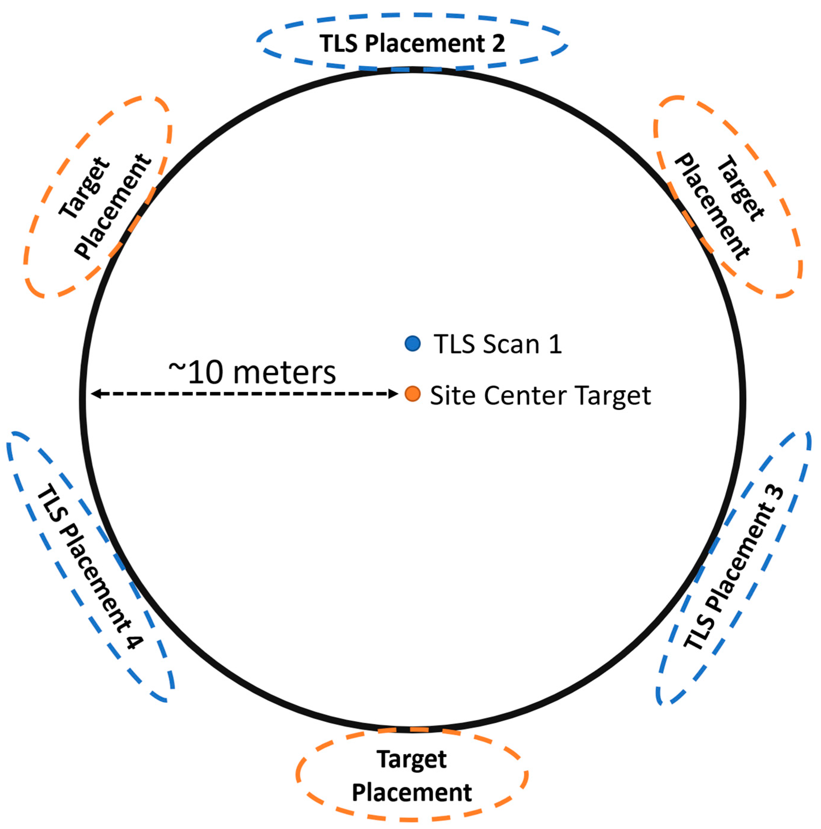
Scanning was performed between October 2021 and September 2022. Scanning was only performed in the summer and early fall. Each site had a center monumented for the RS-FRIS program. TLS scanning was performed with a central scan (scan 1) placed 1 m north of the monumented site center unless that location was heavily occluded by vegetation, in which case the location within 1 m of the site center with the best visibility was used. A TLS target sphere was placed at the site center with three other spheres placed at ~10 m distance from the center in the general directions of 60°, 180°, and 300° magnetic north. Scans 2, 3, and 4 had a generally similar distribution placed at ~10 m distance from the center in the general directions of 0°, 120°, and 240° magnetic north (Figure 2). Each scan location was considered a plot for the TLS metrics derived from a single scan. The edge scans and sphere placement had to have a significant amount of leniency in the actual location. If extremely dense vegetation or a large tree occupied the preferred location of placement, then the closest location to the preferred location that allowed for the surveying of the largest amount of the site was chosen. This scanning location selection criteria inevitably biased the scans against locations with near total occlusion, but that bias was deemed better than potentially missing as much as 50% of an area due to the scanner being placed directly next to a large tree.

2.4. TLS Pre-Processing and Georectification

The pre-processing of the scans was performed in the program FARO Scene [49]. Two different processing workflows were used depending on whether the scans were to be used for the digital cover board (DCB) or voxelization. For the DCB, the scans had all position data removed ensuring that the scan center was at a 0, 0, 0 positional index. No point filtering was applied to the scans to ensure that all potentially valid points were included. TLS noise and edge effects have little effect on the DCB process, as a 2D depth map is created from the point cloud, and the trailing points of an object due to the inherent edge effects of TLS are not visible when creating a raster of the view from the scanner. Removing points through filtering, however, can create gaps in the depth raster, giving an impression of increased openness. A las output file was created from the FARO scene and brought into the open-source lidar-processing program Cloud Compare [50]. Cloud Compare was used to generate a depth map from each TLS scan using the scanning resolution to define the number of rows and columns in the output raster. ASCI image files were produced for each scan.
Pre-processing for the voxelization technique was also performed in FARO Scene. Colorization of the point cloud was performed by applying the color captured by the lidar unit camera to the point clouds. Edge effect filtering as well as the removal of scan points with exceedingly low reflectance values were also performed. Las files were exported from FARO Scene and brought into Cloud Compare. The co-registration of scans was performed within Cloud Compare. Target spheres, tree branches, and ground features were used to place the scans in the correct alignment relative to each other. The scans had a rough approximation of location and elevation from the GPS receiver and altimeter on the FARO unit. The coordinate system was converted into the projection Washington State Plane south (EPSG:2927) to match the coordinate system of the airborne lidar data of the area. The initial approximate location of the TLS scans was used to aid the manually conducted fine registration of the TLS scans to the ALS data. Priority was given to matching the ground points of the TLS and ALS scans rather than the points from the vegetation. X- and y-coordinates of the TLS scans were determined by matching a minimum of 10 shared tree locations between the point clouds, then the z-coordinate was determined by matching ground points. Ground models of sites were created using joined TLS and ALS point clouds. These ground models were used to normalize the height of both the TLS scans and the corresponding ALS point cloud tiles. Lidar point cloud normalization removes elevation from the z-values of the points, so the z-values then reflect the height above the ground. Then, 10 m-radius point cloud clips were taken at each scan plot location from the individual TLS point clouds and the ALS point cloud.

2.5. TLS Digital Cover Board (DCB)

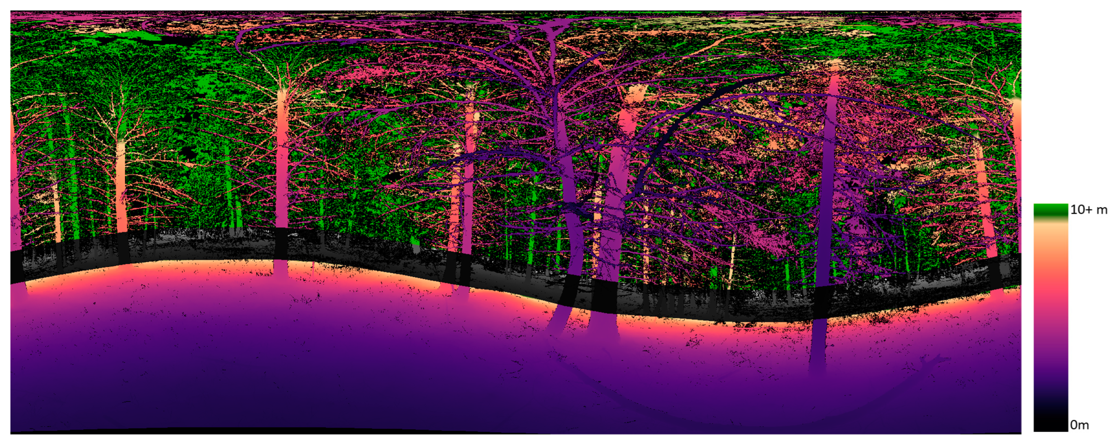
The DCB method is the process of determining, at a defined height increment of the plot, how far each pulse traveled before coming into contact with a surface (depth), as well as determining if a pulse interacted with a surface at all (openness) [45]. A 2D depth map of TLS scans can be created by generating a raster where each pixel represents a location where a laser pulse was sent. This is determined by the scan line resolution when the scan was taken. With a scan line resolution of 0.035° in both the vertical and horizontal axis of the scanner, the resulting raster will have ~10,286 columns (360°/0.035°) and ~4286 rows (150°/0.035°). Each pixel represents the distance traveled by the laser pulse at the angle increment, with a null value returned at locations where there was no pulse return (Figure 3). The value of each pixel is the distance from the scanner. A basic raster analysis can determine which pixels were within a set distance of the scanner, and which pixels exceeded that distance. In areas where there is a constant gradient of distances (i.e., line of sight not occluded by close vegetation), it is possible to identify the location on the horizon of the image a set distance away from the scanner (Figure 3).
We generated two distinctly different sets of metrics from the DCB. The first set used a distance threshold of 10 m radius from the scan position and the second used a distance threshold of 15 m. The 10 m distance was used to match the desired model output resolution of 20 m pixels. The 15 m distance was used to replicate as closely as possible the cover board transect method currently used to assess lynx habitat suitability. For both methods, a vertical swath (ribbon) of pixels, from the 2D depth rasters, contoured to the plot topography was created (Figure 3). A simple horizontal ribbon is not possible unless the scan was taken on a perfectly flat plane. The ribbon will have a high side and a low side on a depth map if the scan was taken on a hill.
With this horizon line identified, a continuous digital cover board can be ribboned around the entire 360° view from the scanner. For the 10 m distance threshold, the height of the ribbon used to represent a 2 m-tall cover board was ~326 pixels. The angular increment from the scanner to a height of 2 m from a distance of 10 m was 11.42° (Figure 4). With every pixel representing a 0.035° scan line, the number of pixels a 2 m-tall cover board would occupy was 11.42°/0.035°, approximately 326. There was some variation in the total number of pixels per digital cover board based on the amount of curvature in the ribbon. This was due to clipping square pixels to fit a curved line. Statistics of this 326-pixel-wide, wave-like ribbon were calculated for the DCB metrics. The metrics derived from this DCB method were the total number of pixels within the ribbon, number of pixels with some value other than null, which represents total cover, total percent cover, number of pixels with a value equal to or less than 10, percentage of pixels with a value less than 10 (i.e., percentage of view with cover within 10 m of plot center), mean distance to cover, and standard deviation of the distance to cover.
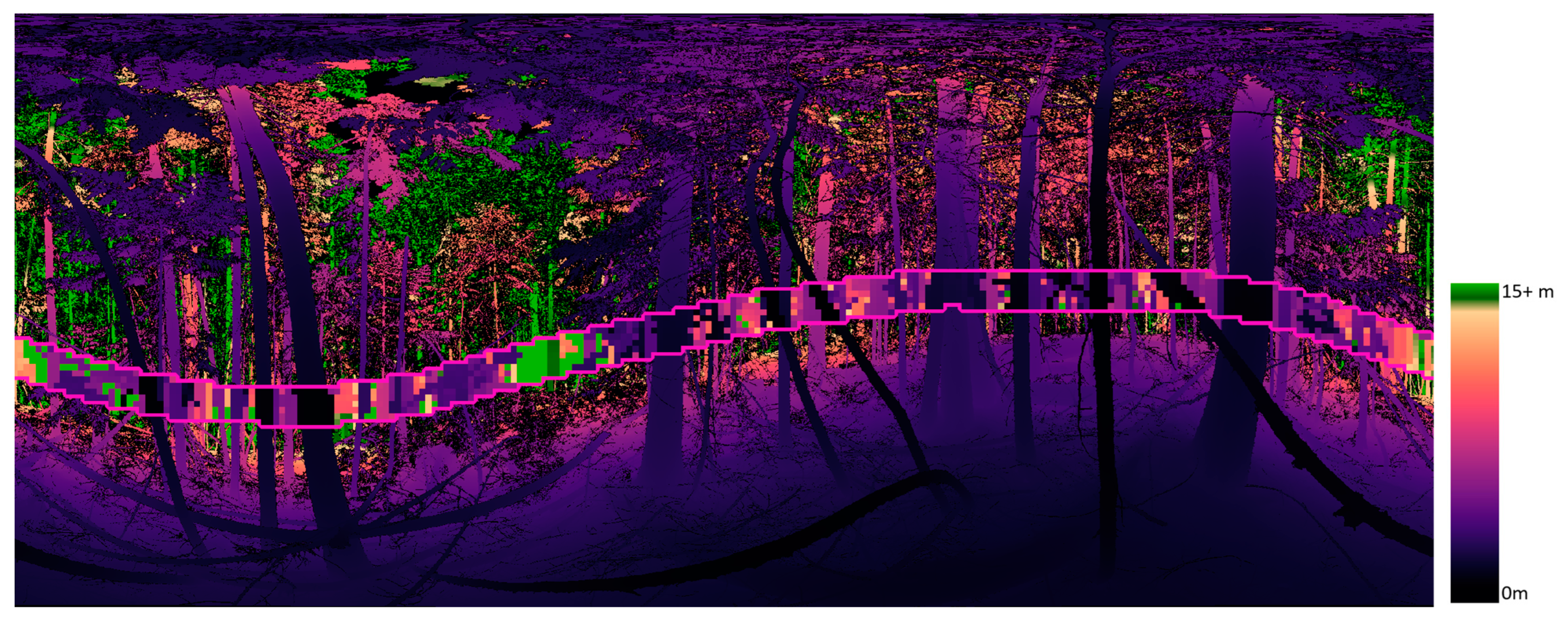
Similarly, for the 15 m distance threshold digital cover board, the horizon line was identified, and a ribbon was placed. To mimic the current cover board protocols [12], we placed a 2 m-tall ribbon 1.5 m above the ground and then subdivided the ribbon into 0.3 m sections as if there were individual 2 m × 0.3 m cover boards surrounding the center scan location. The number of these cover boards that had no vegetation occluding them were counted for each scan (Figure 5).

2.6. TLS Voxelization

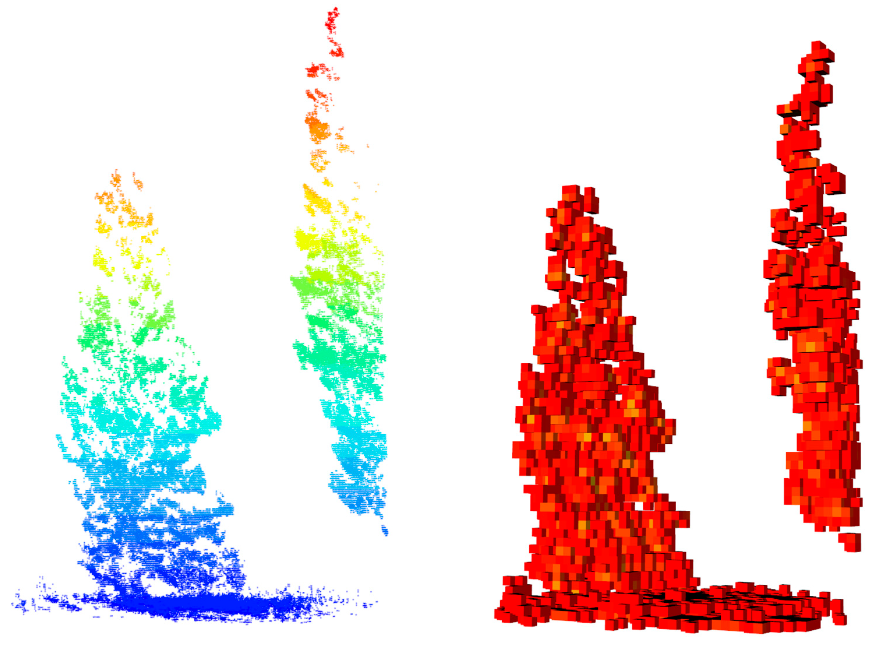
Voxelization is the three-dimensional gridding of the total extent of a point cloud at a defined resolution. To indicate occupancy, a voxel is given a value of 1 if at least one lidar point is within the voxel, and a 0 if no points are within the voxel. A voxel is given a value of 1 whether there is 1 point or 1000+ points within the cell area. This is a method of normalizing the point density across an area, as the point density is inherently higher the closer to the scanner the grid cell is. For all metrics derived from point clouds, the R package lidR was used [51,52]. We chose a voxel size of 10 cm × 10 cm × 10 cm (1000 cm3) (hereafter referred to as simply 10 cm voxel) for each height-normalized point cloud. A 10 cm voxel size has previously been shown to be an optimal size for quantifying viewsheds from TLS and canopy gap estimates [53,54]. Voxelization was performed on each individual scan clipped at 10 m from plot center. Volatilization was not performed on the mosaiced scans, as the variable amount of occlusion at each site would have biased voxel counts toward relatively open areas. The open areas had near-perfect capture of vegetation from the TLS, while sites with dense understory had a large amount of occlusion present. Creating voxel counts from a single-point scan slightly changed the metric measured by the voxelization to the area occupied by vegetation seen from the scanner, rather than being a true measure of the area occupied by vegetation.
The 10 cm voxels were then summarized into 0.5 m-resolution cubes (Figure 6). Voxel metrics were stratified into 0.5 m height bins, so the resulting metrics were expressed in half-meter increments above the ground. Voxel statistics were calculated for all 0.5 m-height strata from the ground to 3 m (Table 1).

2.7. ALS Data

The airborne lidar data covering the entire Loomis State Forest were collected in early June 2016. Data were collected using an Optech Galaxy Lidar System with an average pulse density of ~12 pulses/m2 and a minimum 50% overlap. RGB imagery was used to color the ALS point cloud. The airborne lidar data for the Little Pend Oreille Forest were collected in July 2016, also using an Optech Galaxy Lidar System with an average pulse density of ~3 pulses/m2 and minimum 50% overlap. The 2016 data were the only ALS data available for the study area, resulting in a 5-to-6-year difference between the acquisition of the ALS data and the TLS data; however, good point matching between ALS and TLS scans was still possible.
ALS point clouds were subdivided to test whether a partial cloud produced a better model. Along with the full ALS point cloud, subdivisions using only the first returns, only the last returns, all points less than 2 m above the ground, and all points less than 2 m above the ground but higher than 0.5 m above the ground (Figure 7). Typical ALS metrics using z-values and intensity values were created for each grouping of ALS points (Table 2). In addition to direct measurements of point distributions, ratios of points were also calculated. For each of the point sets, the cumulative percentage of returns (CPR) at nine defined height strata relative to the local z maximum was calculated [55]. The overall relative point density (ORD) and normalized relative point density (NRD) of each point set were also calculated [14].

2.8. Statistical Analysis

An overabundance of metrics was produced from both the TLS and ALS data. An exploratory analysis was conducted to determine (1) which TLS metrics best described the variation among plots, (2) whether regression models or categorical data and machine-learning modeling produced the best results, and (3) which subset of ALS metrics either had the highest correlation with the TLS data or were the best performing predictors in a machine-learning approach.
A principal component analysis was performed on the 42 TLS metrics to determine which metrics best described the variation between plots. All metrics were normalized before the PCA analysis. TLS metrics that contributed highly to the first principal component (PC1) were used for a full stepwise regression analysis with all derived ALS metrics. They were also broken into ordinal categories of high and low understory cover to be used in the training and testing of the machine-learning algorithms random forest and extreme gradient boosting (xgboost) using a split of 70% training and 30% testing [30].

3. Results

3.1. TLS PCA

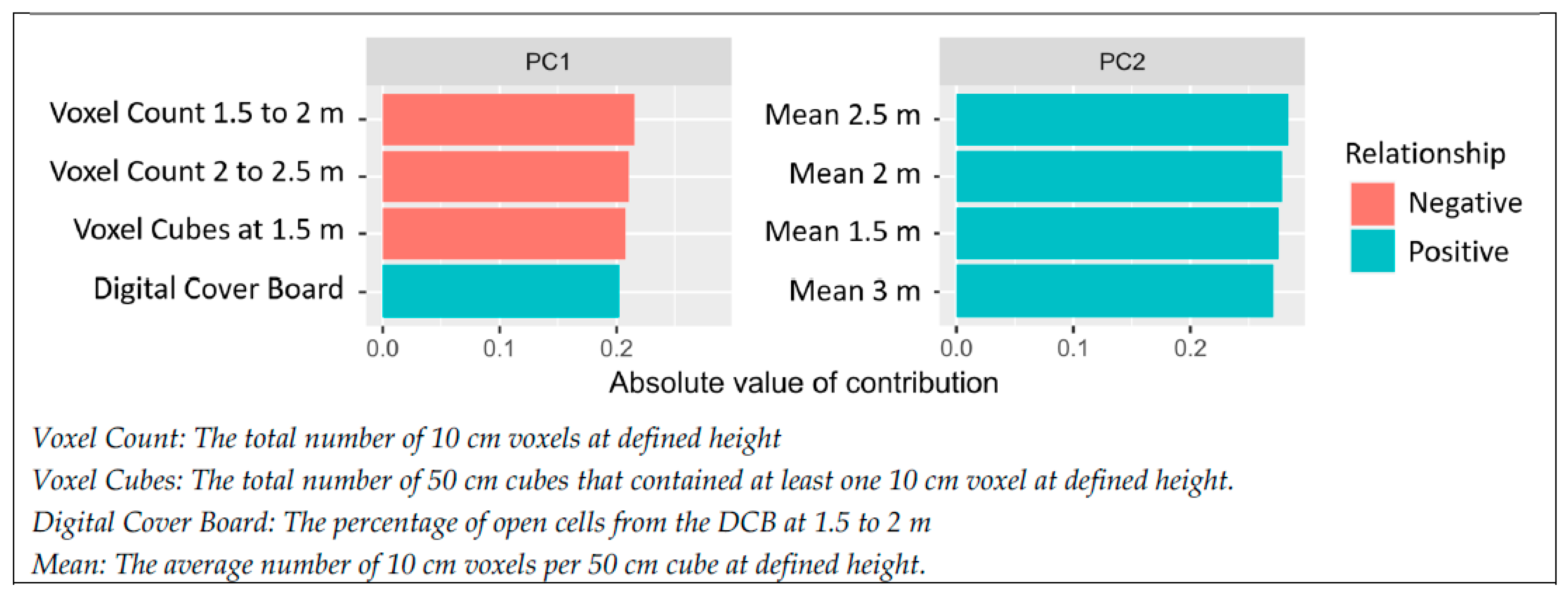
Of the 42 TLS metrics that were used for the PCA, the four metrics that most contributed to the principal component axis 1 were voxel count at 1.5 to 2 m, voxel count at 2 to 2.5 m, voxel cubes at 1.5 m, and the digital cover board. These four metrics will be referred to as “PC1 Metrics” hereinafter. The four metrics that most contributed to the principal component axis 2 were the means of the height strata of 2.5 m to 3 m, 2 m to 2.5 m, 1.5 to 2 m, and 3 m to 3.5 m (Figure 8 and Figure 9).
Our 15 m DCB metric that followed the current lynx management criteria of determining the percentage of fully visible coverboard quadrants at 1.5 m to 2 m height was not a significant contributor to PC1 or PC2; however, the count of DCB cells visible at 15 m was the fourth highest contributor to PC1.
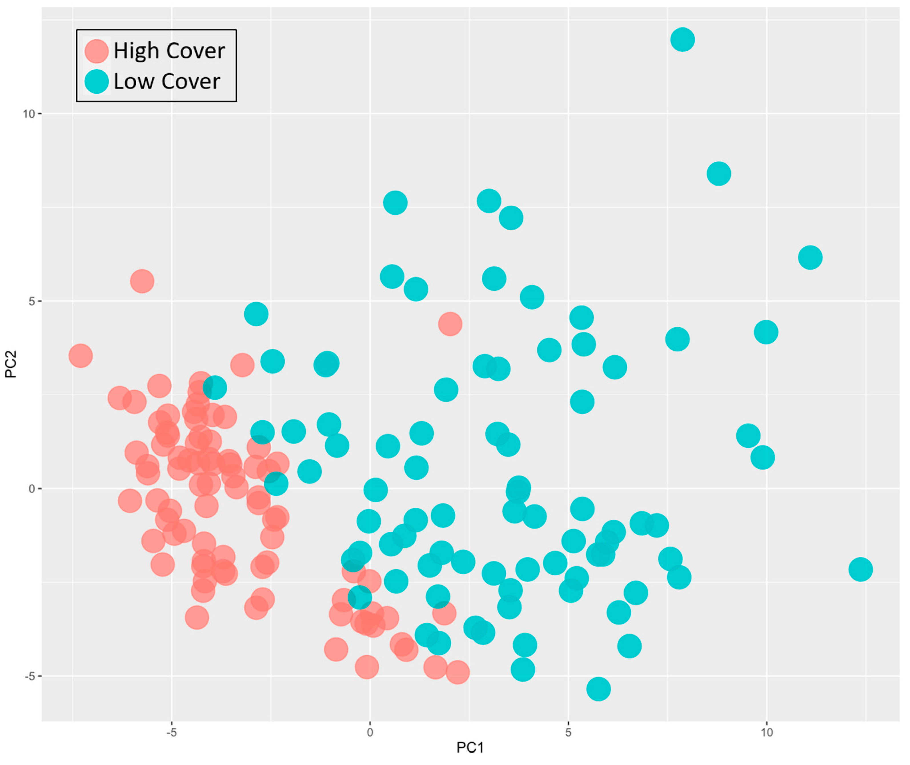
The PCA plot of the TLS metrics is presented in Figure 9. High-cover and low-cover classes were determined by using the DCB percentage metric with plots having more than 90% occluded cells counting as cover. There was an even split of plots that were high cover (80 plots) vs. low cover (80 plots) in our data.

3.2. Models

Models were developed to predict TLS cover metrics from ALS metrics to produce area-wide rasters of predicted TLS cover metrics. All models performed worse when combining the data from the Loomis State Forest with the data from Little Pend Oreille State Forest. For all of the final models, the Loomis State Forest data were run alone. The Loomis State Forest had 32 of the 40 total sites. With each site comprised of 4 scan plots, 128 plots were used for the modeling. Using a 70% training, 30% testing split, 90 plots were used for training with 38 plots used for testing.

3.2.1. Regression

A stepwise regression analysis was performed using each of the individual TLS understory horizontal cover metrics that most contributed to PC1, and the collection of ALS metrics. While there were statistically significant relationships between each of the four TLS cover metrics and a collection of the ALS metrics using a forward and backwards stepwise regression analysis (p < 0.05), the R2 values did not increase above 0.3. We were not able to find a satisfactory regression model to predict any of the TLS horizontal cover metrics from ALS.

3.2.2. Machine Learning

The four PC1 metrics were converted into ordinal data of high cover and low cover, with 50% of the training data (45 plots) assigned the high-cover label and the other half assigned the low-cover label. For the DCB metric, the high-cover class was comprised of plots with greater than 90% cover, and the low-cover class was plots that had less than 90% cover. This threshold of 90% cover corresponds to the WA DNR protocols of 4 or fewer open views out of the 40 observations being considered to have sufficient cover for a forage habitat (see Section 1.2).
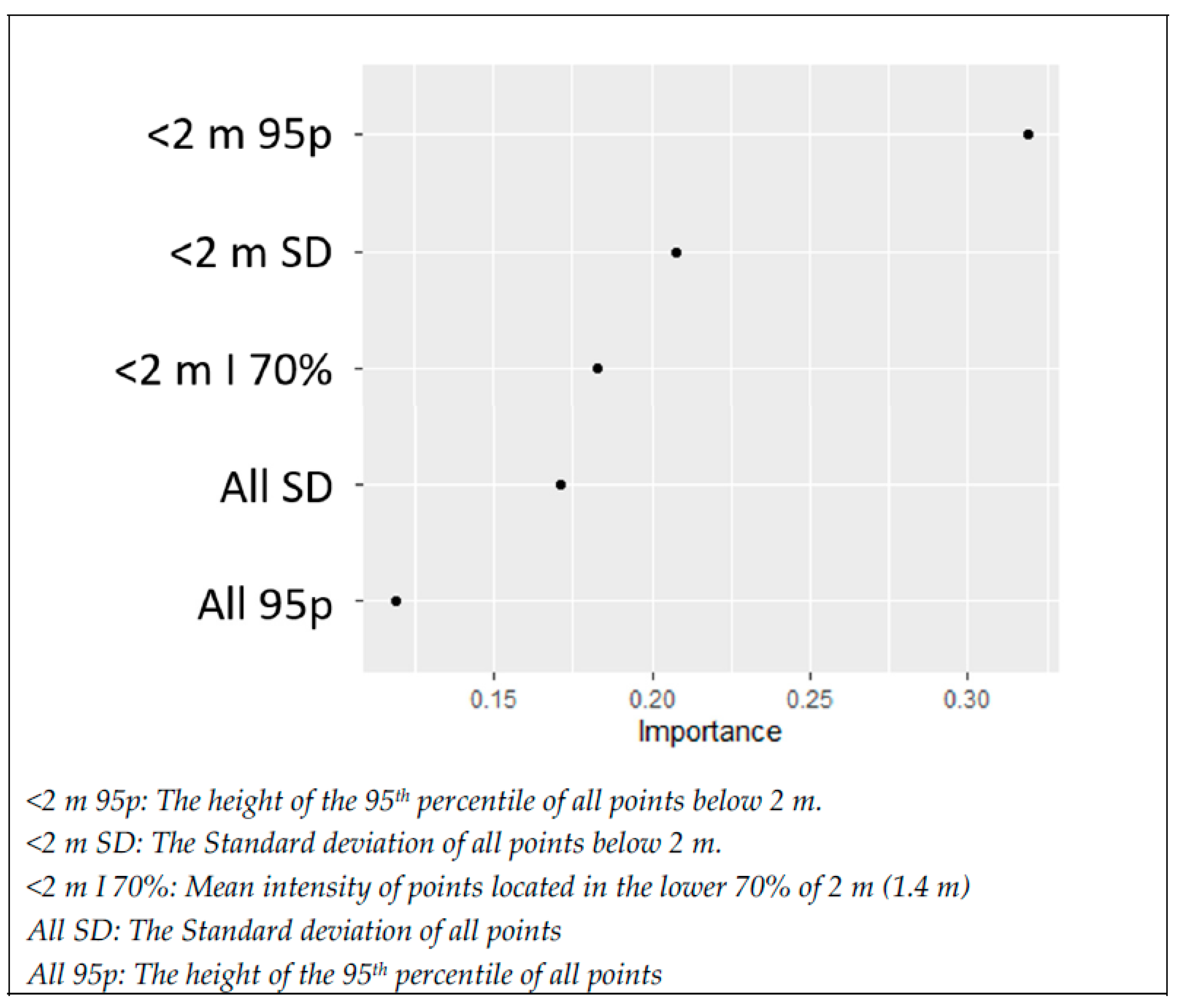
Xgboost produced higher-accuracy models than random forest. The xgboost models using ALS data to predict the ordinal cover class from TLS data had a total accuracy of less than 70% when using the high cover/low cover split as determined from each of the three voxel-based PC1 metrics (voxel count 1.5 to 2 m, voxel count 2 to 2.5 m, and voxel cubes at 1.5 m). However, using the DCB PC1 metric, a model accuracy of 85% was achieved with the testing data, with the area under the ROC curve set at 0.92. Of the 284 ALS metrics that were used in the model, 279 were removed from the final model, as only 5 ALS metrics were needed to produce our final model <2 m 95p, <2 m SD, <2 m I 70%, all SD, all 95p (Figure 10).

3.2.3. Model Output

The xgboost model produced a binary model of low cover/high cover. A third category (no cover) was added to the final model output of (Figure 11). This third category was created by labeling all areas with no ALS returns greater than 2 m as no cover. This accounted for the areas within Loomis that were not forested.

4. Discussion

4.1. TLS Metrics

The TLS metrics that accounted for the greatest amount of variation between plots all related to a vegetation structure between 1.5 and 2 m above ground level (Figure 7). This corresponds to the vegetation height stratum that is considered important for snowshoe hare and thus lynx habitats [3,56,57]. This validates our TLS metrics as ecologically meaningful for quantifying a difference between poor habitat structure and preferred habitat structure. Of the four metrics that accounted for the greatest plot variability, our digital cover board metric produced the best model. Terrestrial lidar has been shown to be effective at quantifying horizontal cover [41,45,54], so we did not directly compare our metrics with traditional methods such as cover boards. While we believe our metrics are robust measurements of horizontal cover, more research should be conducted to explore relationships between TLS metrics and population data for snowshoe hare beyond a quantification of cover.
The number of studies using TLS for habitat characterization is increasing, as well as the sophistication of the approaches. For example, a form of the DCB metric has been previously used to quantify forest structure [45,46], but this study is the first we are aware of that directly applies this approach to habitat quantification. There has been previous work using TLS for understory habitat classification [58,59], as well as excellent R packages that have been developed to quantify the viewshed specifically for habitat characterization [60]. The advantage of our metrics is the ability to be applied to single-point TLS scans as well as account for slope. This work and others speak to the utility of this technology to produce high-fidelity and objective estimates of forest structure related to the habitat requirements for numerous different species.
One limitation of the TLS voxel methods is that the voxel counts were derived from a single-point scan. The final voxel counts were measurements of “How much stuff is visible from the scanner location” and not a true measurement of “How much stuff is there”. While there are drawbacks to single-point scans, they are similar to ocular estimates of cover made by an observer at a single point. To fully utilize a voxelization method, multiple scans stitched together must be used for a near complete scan of all vegetation structures [61,62]. Having a near-complete scan of all the vegetation from multiple scans is relatively easy in open stands; however, many of our stands had dense understory vegetation with high amounts of occlusion. In such areas, the amount of single-point scans that would have been required for a complete sampling was infeasible to collect. Further, with every additional scan compiled into a stitched together TLS scene, the likelihood of error increases due to either slight misalignments between scans or some environmental factor such as wind actually moving the vegetation. Using single scans allowed for the method to be applied universally across stands. Using a mobile terrestrial lidar unit such as a backpack or wand device may allow for better data collection in regards to voxelization, but it would be unlikely that quality depth rasters could be produced given the lower level of point accuracy inherent in mobile lidar units [63,64].

4.2. ALS Metrics

The ALS data were collected in 2016 while the TLS data were collected in 2022. This 6-year time gap, a common occurrence in remote sensing research, presented some additional challenges beyond a normal ALS/TLS alignment. While the 2016 ALS data were the most recent lidar data available, there were areas where significant disturbances occurred (e.g., logging and fire) in the interim that had to be removed from the analysis. That we were still able to produce a model with 85% accuracy despite this age gap indicates the utility of lidar acquisitions for forest structure characterization years after the initial lidar acquisition, where tree growth rates are relatively slow, as in this study area.
ALS area-based metrics typically look at the vertical arrangement of points within a defined plot size. Characterizing the vertical arrangement of points using simple metrics has been the subject of extensive research. The percentile heights of points is one of the most common metrics derived from lidar along with ratios of points below and above a defined threshold [17,65,66,67]. For our study, we derived 286 different metrics from ALS informed by reviewing methods used in previous forest structure research. We identified 5 metrics from the 286 that allowed for a high model fit using xgboost. Three of the five metrics used a subset of the point cloud of points below 2 m, while the other two metrics used all of the point returns. The 95th percentile height and the SD of points are lidar metrics that have been shown to be useful when modeling forest structural elements such as tree height, biomass, basal area, and quadratic mean diameter [68,69,70]. It is unsurprising that these metrics that are commonly used for modeling biomass are also useful when modeling horizontal cover. The combination of using these metrics from both the full point cloud as well as the points below 2 m may indicate that for future studies utilizing ALS for forest structure characterization, combining subsets of the data along with the full point cloud may provide more robust models. The fifth metric used was the mean intensity of points located in the lower 70% of 2 m (1.4 m). An important caveat when using intensity values from aerial lidar is that they are usually not calibrated to permit comparison between acquisitions [71,72]. Intensity values vary depending on the distance, angle, and surface that is reflecting the lidar pulse [73,74]. That different surfaces return different lidar intensity is likely the key to why it is an important predictor of understory vegetation conditions. If in the lower 1.4 m of a forest there is a lot of vegetation, then a different intensity value should be received than if there is a lack of vegetation and more visible soils or duff. When working within a single ALS acquisition, lidar intensity without calibration can still be effectively used to aid in differentiation between ground cover classes [75,76].

4.3. Model Fit

Our 85% accuracy rate was achieved when using only the Loomis State Forest plots and the Loomis ALS data. We had to remove our Little Pend Oreille plots from the analysis. We felt it was important to include the mention that both study areas were initially collected for analysis because it illustrates that a model generated using lidar data from one lidar acquisition may not be applicable to a different lidar data set collected with a different pulse density in a different forest. A model could not be generated that performed well for both forests. With only eight sites located within the Little Pend Oreille State Forest, it is reasonable to assume that our poor model fits for the area were partially due to the small sample size.
Our model also did not consider spatial autocorrelation between plots. Previous work producing landscape models from remote sensing data leveraged spatial autocorrelation to improve overall model fits [77]. Our methods were not reliant on spatial interpolation to derive a final model, but rather depended on the vertical distribution of lidar points for the model fit regardless of the x, y location of the raster cell. Errors or enhancements for model fits due to spatial autocorrelation are of the most concern when using interpolation methods [78,79].

5. Conclusions

Our final model output was a 20 m-resolution raster of three horizontal-cover classes (no cover, low cover, and high cover). No filtering was applied when identifying contiguous areas of high cover large enough to meet lynx habitat requirements. Our model outputs showed whether each individual 20 m grid cell had ALS point values that were likely to be indicative of high or low horizontal cover. We concluded that our model of understory horizontal cover could be used in conjunction with other key habitat considerations to inform a more holistic and connectivity-sensitive habitat model.
Beyond the utility of TLS to generate an objective measurement of understory horizontal cover, we believe that other important forest metrics could also be modeled with our TLS metrics. TLS is already widely used to quantify biomass, map tree stems, and determine tree diameters and other forest metrics [80,81,82,83], but the utility of single-point TLS scans for forest mensuration needs more research. We feel that our approach to spatial modeling from single-point TLS scans will be of great interest to forest managers and conservationists in need of an objective and time efficient method to quantify horizontal cover as it relates to habitat suitability for other wildlife species, among broader applications such as forest inventory and carbon storage.

Author Contributions

Conceptualization, J.L.B. and P.G.; methodology, J.L.B. and P.G.; software, J.L.B.; validation, J.L.B., P.G., A.T.H. and L.M.M.; formal analysis, J.L.B. and A.T.H.; investigation, J.L.B.; resources, P.G. and L.M.M.; data curation, J.L.B.; writing—original draft preparation, J.L.B.; writing—review and editing, A.T.H. and L.M.M.; visualization, J.L.B.; supervision, L.M.M.; project administration, J.L.B. and L.M.M.; funding acquisition, J.L.B. and P.G. All authors have read and agreed to the published version of the manuscript.

Funding

This research was funded by Washington Department of Natural Resources. The Precision Forestry Cooperative, University of Washington and in part by the USDA Forest Service, Rocky Mountain Research Station.

Data Availability Statement

Data available upon request.

Acknowledgments

We would like to thank and acknowledge the contributions of Miles Micheletti and Grant Johnson for field data collection; Kate McBurney and Jeffrey Ricklefs for coordination and oversight; and the reviewers and editors that contributed to the final version of this manuscript.

Conflicts of Interest

This research was supported in part by the USDA Forest Service, Rocky Mountain Research Station. The findings and conclusions in this publication are those of the authors and should not be construed to represent any official USDA or U.S. Government determination or policy.

References

  1. US Fish Wildlife Service. Species Status Assessment for the Canada Lynx (Lynx canadensis) Contiguous United States Distinct Population Segment; Version 10; US Fish Wildlife Service: Lakewood, CA, USA, 2017.
  2. Elton, C.; Nicholson, M. The Ten-Year Cycle in Numbers of the Lynx in Canada. J. Anim. Ecol. 1942, 11, 215–244. [Google Scholar] [CrossRef]
  3. Koehler, G.M. Population and Habitat Characteristics of Lynx and Snowshoe Hares in North Central Washington. Can. J. Zool. 1990, 68, 845–851. [Google Scholar] [CrossRef]
  4. Koehler, G.M.; Gm, K.; Mg, H.; Hs, H. Lynx Movements and Habitat Use in Montana. Can. Field-Nat. 1979, 93, 441–442. [Google Scholar]
  5. Murray, D.L.; Boutin, S.; O’Donoghue, M. Winter Habitat Selection by Lynx and Coyotes in Relation to Snowshoe Hare Abundance. Can. J. Zool. 1994, 72, 1444–1451. [Google Scholar] [CrossRef]
  6. Parker, G.R.; Maxwell, J.W.; Morton, L.D.; Smith, G.E.J. The Ecology of the Lynx (Lynx canadensis) on Cape Breton Island. Can. J. Zool. 1983, 61, 770–786. [Google Scholar] [CrossRef]
  7. Poole, K.G. A Review of the Canada Lynx, Lynx canadensis, in Canada. Can. Field-Nat. 2003, 117, 360–376. [Google Scholar] [CrossRef]
  8. Poole, K.G. Characteristics of an Unharvested Lynx Population during a Snowshoe Hare Decline. J. Wildl. Manag. 1994, 58, 608–618. [Google Scholar] [CrossRef]
  9. Fuller, A.K.; Harrison, D.J. Movement Paths Reveal Scale-Dependent Habitat Decisions by Canada Lynx. J. Mammal. 2010, 91, 1269–1279. [Google Scholar] [CrossRef]
  10. Ivan, J.S.; Shenk, T.M. Winter Diet and Hunting Success of Canada Lynx in Colorado. J. Wildl. Manag. 2016, 80, 1049–1058. [Google Scholar] [CrossRef]
  11. Maletzke, B.T.; Koehler, G.M.; Wielgus, R.B.; Aubry, K.B.; Evans, M.A. Habitat Conditions Associated with Lynx Hunting Behavior during Winter in Northern Washington. J. Wildl. Manag. 2008, 72, 1473–1478. [Google Scholar] [CrossRef]
  12. Quade, C.; Minkova, T. 2006 Washington DNR Lynx Management Plan; Washington State Department of Natural Resources: Olympia, WA, USA, 2006.
  13. Collins, W.B.; Becker, E.F. Estimation of Horizontal Cover. J. Range Manag. 2001, 54, 67–70. [Google Scholar] [CrossRef]
  14. Campbell, M.J.; Dennison, P.E.; Hudak, A.T.; Parham, L.M.; Butler, B.W. Quantifying Understory Vegetation Density Using Small-Footprint Airborne Lidar. Remote Sens. Environ. 2018, 215, 330–342. [Google Scholar] [CrossRef]
  15. Jorgensen, C.F.; Stutzman, R.J.; Anderson, L.C.; Decker, S.E.; Powell, L.A.; Schacht, W.H.; Fontaine, J.J. Choosing a DIVA: A Comparison of Emerging Digital Imagery Vegetation Analysis Techniques. Appl. Veg. Sci. 2013, 16, 552–560. [Google Scholar] [CrossRef]
  16. Beland, M.; Parker, G.; Sparrow, B.; Harding, D.; Chasmer, L.; Phinn, S.; Antonarakis, A.; Strahler, A. On Promoting the Use of Lidar Systems in Forest Ecosystem Research. For. Ecol. Manag. 2019, 450, 117484. [Google Scholar] [CrossRef]
  17. Coops, N.C.; Tompalski, P.; Goodbody, T.R.; Queinnec, M.; Luther, J.E.; Bolton, D.K.; White, J.C.; Wulder, M.A.; van Lier, O.R.; Hermosilla, T. Modelling Lidar-Derived Estimates of Forest Attributes over Space and Time: A Review of Approaches and Future Trends. Remote Sens. Environ. 2021, 260, 112477. [Google Scholar] [CrossRef]
  18. Bouvier, M.; Durrieu, S.; Fournier, R.A.; Renaud, J.-P. Generalizing Predictive Models of Forest Inventory Attributes Using an Area-Based Approach with Airborne LiDAR Data. Remote Sens. Environ. 2015, 156, 322–334. [Google Scholar] [CrossRef]
  19. Hudak, A.T.; Strand, E.K.; Vierling, L.A.; Byrne, J.C.; Eitel, J.U.; Martinuzzi, S.; Falkowski, M.J. Quantifying Aboveground Forest Carbon Pools and Fluxes from Repeat LiDAR Surveys. Remote Sens. Environ. 2012, 123, 25–40. [Google Scholar] [CrossRef]
  20. Hudak, A.T.; Evans, J.S.; Stuart Smith, A.M. LiDAR Utility for Natural Resource Managers. Remote Sens. 2009, 1, 934–951. [Google Scholar] [CrossRef]
  21. Zhao, K.; Popescu, S.; Meng, X.; Pang, Y.; Agca, M. Characterizing Forest Canopy Structure with Lidar Composite Metrics and Machine Learning. Remote Sens. Environ. 2011, 115, 1978–1996. [Google Scholar] [CrossRef]
  22. Zheng, G.; Ma, L.; Eitel, J.U.H.; He, W.; Magney, T.S.; Moskal, L.M.; Li, M. Retrieving Directional Gap Fraction, Extinction Coefficient, and Effective Leaf Area Index by Incorporating Scan Angle Information From Discrete Aerial Lidar Data. IEEE Trans. Geosci. Remote Sens. 2017, 55, 577–590. [Google Scholar] [CrossRef]
  23. García-Gutiérrez, J.; Martínez-Álvarez, F.; Troncoso, A.; Riquelme, J.C. A Comparison of Machine Learning Regression Techniques for LiDAR-Derived Estimation of Forest Variables. Neurocomputing 2015, 167, 24–31. [Google Scholar] [CrossRef]
  24. Gleason, C.J.; Im, J. Forest Biomass Estimation from Airborne LiDAR Data Using Machine Learning Approaches. Remote Sens. Environ. 2012, 125, 80–91. [Google Scholar] [CrossRef]
  25. Weiss, U.; Biber, P.; Laible, S.; Bohlmann, K.; Zell, A. Plant Species Classification Using a 3D LIDAR Sensor and Machine Learning. In Proceedings of the 2010 Ninth International Conference on Machine Learning and Applications, Washington, DC, USA, 12–14 December 2010; pp. 339–345. [Google Scholar]
  26. Marrs, J.; Ni-Meister, W. Machine Learning Techniques for Tree Species Classification Using Co-Registered LiDAR and Hyperspectral Data. Remote Sens. 2019, 11, 819. [Google Scholar] [CrossRef]
  27. Lee, J.; Im, J.; Kim, K.; Quackenbush, L.J. Machine Learning Approaches for Estimating Forest Stand Height Using Plot-Based Observations and Airborne LiDAR Data. Forests 2018, 9, 268. [Google Scholar] [CrossRef]
  28. Farhani, G.; Sica, R.J.; Daley, M.J. Classification of Lidar Measurements Using Supervised and Unsupervised Machine Learning Methods. Atmos. Meas. Tech. 2021, 14, 391–402. [Google Scholar] [CrossRef]
  29. Teri, S.S.; Musliman, I.A. Machine Learning in Big Lidar Data: A Review. Int. Arch. Photogramm. Remote Sens. Spat. Inf. Sci. 2019, XLII-4-W16, 641–644. [Google Scholar] [CrossRef]
  30. Chen, T.; Guestrin, C. Xgboost: A Scalable Tree Boosting System. In Proceedings of the 22nd ACM Sigkdd International Conference on Knowledge Discovery and Data Mining, San Francisco, CA, USA, 13–17 August 2016; pp. 785–794. [Google Scholar]
  31. Liu, M.; Han, Z.; Chen, Y.; Liu, Z.; Han, Y. Tree Species Classification of LiDAR Data Based on 3D Deep Learning. Measurement 2021, 177, 109301. [Google Scholar] [CrossRef]
  32. Liu, H.; Shen, X.; Cao, L.; Yun, T.; Zhang, Z.; Fu, X.; Chen, X.; Liu, F. Deep Learning in Forest Structural Parameter Estimation Using Airborne Lidar Data. IEEE J. Sel. Top. Appl. Earth Obs. Remote Sens. 2020, 14, 1603–1618. [Google Scholar] [CrossRef]
  33. Marinelli, D.; Paris, C.; Bruzzone, L. An Approach Based on Deep Learning for Tree Species Classification in LiDAR Data Acquired in Mixed Forest. IEEE Geosci. Remote Sens. Lett. 2022, 19, 1–5. [Google Scholar] [CrossRef]
  34. Blomdahl, E.M.; Thompson, C.M.; Kane, J.R.; Kane, V.R.; Churchill, D.; Moskal, L.M.; Lutz, J.A. Forest Structure Predictive of Fisher (Pekania Pennanti) Dens Exists in Recently Burned Forest in Yosemite, California, USA. For. Ecol. Manag. 2019, 444, 174–186. [Google Scholar] [CrossRef]
  35. Johnston, A.N.; Moskal, L.M. High-Resolution Habitat Modeling with Airborne LiDAR for Red Tree Voles. J. Wildl. Manag. 2017, 81, 58–72. [Google Scholar] [CrossRef]
  36. North, M.P.; Kane, J.T.; Kane, V.R.; Asner, G.P.; Berigan, W.; Churchill, D.J.; Conway, S.; Gutiérrez, R.J.; Jeronimo, S.; Keane, J.; et al. Cover of Tall Trees Best Predicts California Spotted Owl Habitat. For. Ecol. Manag. 2017, 405, 166–178. [Google Scholar] [CrossRef]
  37. Tymen, B.; Vincent, G.; Courtois, E.A.; Heurtebize, J.; Dauzat, J.; Marechaux, I.; Chave, J. Quantifying Micro-Environmental Variation in Tropical Rainforest Understory at Landscape Scale by Combining Airborne LiDAR Scanning and a Sensor Network. Ann. For. Sci. 2017, 74, 32. [Google Scholar] [CrossRef]
  38. Venier, L.A.; Swystun, T.; Mazerolle, M.J.; Kreutzweiser, D.P.; Wainio-Keizer, K.L.; McIlwrick, K.A.; Woods, M.E.; Wang, X. Modelling Vegetation Understory Cover Using LiDAR Metrics. PLoS ONE 2019, 14, e0220096. [Google Scholar] [CrossRef]
  39. Wing, B.M.; Ritchie, M.W.; Boston, K.; Cohen, W.B.; Gitelman, A.; Olsen, M.J. Prediction of Understory Vegetation Cover with Airborne Lidar in an Interior Ponderosa Pine Forest. Remote Sens. Environ. 2012, 124, 730–741. [Google Scholar] [CrossRef]
  40. Fekety, P.A.; Sadak, R.B.; Sauder, J.D.; Hudak, A.T.; Falkowski, M.J. Predicting Forest Understory Habitat for Canada Lynx Using LIDAR Data. Wildl. Soc. Bull. 2019, 43, 619–629. [Google Scholar] [CrossRef]
  41. Olsoy, P.J.; Forbey, J.S.; Rachlow, J.L.; Nobler, J.D.; Glenn, N.F.; Shipley, L.A. Fearscapes: Mapping Functional Properties of Cover for Prey with Terrestrial LiDAR. BioScience 2015, 65, 74–80. [Google Scholar] [CrossRef]
  42. Huang, H.; Gong, P.; Cheng, X.; Clinton, N.; Cao, C.; Ni, W.; Li, Z.; Wang, L. Forest Structural Parameter Extraction Using Terrestrial LiDAR. In Proceedings of the SilviLaser 2009, Station, TX, USA, 14–16 October 2009. [Google Scholar]
  43. Ashcroft, M.B.; Gollan, J.R.; Ramp, D. Creating Vegetation Density Profiles for a Diverse Range of Ecological Habitats Using Terrestrial Laser Scanning. Methods Ecol. Evol. 2014, 5, 263–272. [Google Scholar] [CrossRef]
  44. Wallace, L.; Hally, B.; Hillman, S.; Jones, S.D.; Reinke, K. Terrestrial Image-Based Point Clouds for Mapping Near-Ground Vegetation Structure: Potential and Limitations. Fire 2020, 3, 59. [Google Scholar] [CrossRef]
  45. Batchelor, J.L.; Wilson, T.M.; Olsen, M.J.; Ripple, W.J. New Structural Complexity Metrics for Forests from Single Terrestrial Lidar Scans. Remote Sens. 2023, 15, 145. [Google Scholar] [CrossRef]
  46. Richardson, J.J.; Moskal, L.M.; Bakker, J.D. Terrestrial Laser Scanning for Vegetation Sampling. Sensors 2014, 14, 20304–20319. [Google Scholar] [CrossRef] [PubMed]
  47. Washington State Department of Natural Resources Loomis State Forest Landscape Plan. 1996. Available online: https://www.dnr.wa.gov/publications/lm_loomis_sec4.pdf (accessed on 25 August 2023).
  48. Gould, P.; Strunk, J.; Tenneson, K. Introducing the Remote Sensing Forest Inventory System (RS-FRIS); Version 1.0. Revision 1; Internal Document; Washington State Department of Natural Resources: Olympia, WA, USA, 2015.
  49. FARO Scene [Computer Software], Version 2019.2 (7.5.5.4303); FARO: Lake Mary, FL, USA, 2021. Available online: http://www.faro.com (accessed on 25 August 2023).
  50. CloudCompare [Computer Software], Version 2.11; 2019. Available online: http://www.cloudcompare.org (accessed on 1 March 2021).
  51. Roussel, J.-R.; Auty, D.; Coops, N.C.; Tompalski, P.; Goodbody, T.R.; Meador, A.S.; Bourdon, J.-F.; De Boissieu, F.; Achim, A. LidR: An R Package for Analysis of Airborne Laser Scanning (ALS) Data. Remote Sens. Environ. 2020, 251, 112061. [Google Scholar] [CrossRef]
  52. Roussel, J.-R.; Auty, D. lidR (version 3.1.2) R Package. 2021. Available online: https://github.com/r-lidar/lidR (accessed on 6 September 2023).
  53. Ross, C.W.; Loudermilk, E.L.; Skowronski, N.; Pokswinski, S.; Hiers, J.K.; O’Brien, J. LiDAR Voxel-Size Optimization for Canopy Gap Estimation. Remote Sens. 2022, 14, 1054. [Google Scholar] [CrossRef]
  54. Zong, X.; Wang, T.; Skidmore, A.K.; Heurich, M. The Impact of Voxel Size, Forest Type, and Understory Cover on Visibility Estimation in Forests Using Terrestrial Laser Scanning. GIScience Remote Sens. 2021, 58, 323–339. [Google Scholar] [CrossRef]
  55. Woods, M.; Lim, K.; Treitz, P. Predicting Forest Stand Variables from LiDAR Data in the Great Lakes—St. Lawrence Forest of Ontario. For. Chron. 2008, 84, 827–839. [Google Scholar] [CrossRef]
  56. Litvaitis, J.A.; Sherburne, J.A.; Bissonette, J.A. Influence of Understory Characteristics on Snowshoe Hare Habitat Use and Density. J. Wildl. Manag. 1985, 49, 866–873. [Google Scholar] [CrossRef]
  57. Vanbianchi, C.; Gaines, W.L.; Murphy, M.A.; Pither, J.; Hodges, K.E. Habitat Selection by Canada Lynx: Making Do in Heavily Fragmented Landscapes. Biodivers. Conserv. 2017, 26, 3343–3361. [Google Scholar] [CrossRef]
  58. Burgett, S.; Rachlow, J.; Stein, R. Unexpected Properties of Habitat Altered by Ecosystem Engineers: A Pygmy Rabbit Case Study. Available online: https://scholarworks.boisestate.edu/icur/2021/poster_session/12/ (accessed on 16 December 2022).
  59. Galluzzi, M.; Puletti, N.; Armanini, M.; Chirichella, R.; Mustoni, A. Mobile Laser Scanner Understory Characterization: An Exploratory Study on Hazel Grouse in Italian Alps. bioRxiv 2022. [Google Scholar] [CrossRef]
  60. Lecigne, B.; Eitel, J.; Rachlow, J. Viewshed3d: An R Package for Quantifying 3D Visibility Using Terrestrial Lidar Data. Methods Ecol. Evol. 2020, 11, 733–738. [Google Scholar] [CrossRef]
  61. Béland, M.; Baldocchi, D.D.; Widlowski, J.-L.; Fournier, R.A.; Verstraete, M.M. On Seeing the Wood from the Leaves and the Role of Voxel Size in Determining Leaf Area Distribution of Forests with Terrestrial LiDAR. Agric. For. Meteorol. 2014, 184, 82–97. [Google Scholar] [CrossRef]
  62. Soma, M.; Pimont, F.; Dupuy, J.-L. Sensitivity of Voxel-Based Estimations of Leaf Area Density with Terrestrial LiDAR to Vegetation Structure and Sampling Limitations: A Simulation Experiment. Remote Sens. Environ. 2021, 257, 112354. [Google Scholar] [CrossRef]
  63. Bauwens, S.; Bartholomeus, H.; Calders, K.; Lejeune, P. Forest Inventory with Terrestrial LiDAR: A Comparison of Static and Hand-Held Mobile Laser Scanning. Forests 2016, 7, 127. [Google Scholar] [CrossRef]
  64. Donager, J.J.; Sánchez Meador, A.J.; Blackburn, R.C. Adjudicating Perspectives on Forest Structure: How Do Airborne, Terrestrial, and Mobile Lidar-Derived Estimates Compare? Remote Sens. 2021, 13, 2297. [Google Scholar] [CrossRef]
  65. Gobakken, T.; Næsset, E. Weibull and Percentile Models for Lidar-Based Estimation of Basal Area Distribution. Scand. J. For. Res. 2005, 20, 490–502. [Google Scholar] [CrossRef]
  66. Qu, Y.; Shaker, A.; Silva, C.A.; Klauberg, C.; Pinagé, E.R. Remote Sensing of Leaf Area Index from LiDAR Height Percentile Metrics and Comparison with MODIS Product in a Selectively Logged Tropical Forest Area in Eastern Amazonia. Remote Sens. 2018, 10, 970. [Google Scholar] [CrossRef]
  67. Simonson, W.D.; Allen, H.D.; Coomes, D.A. Applications of Airborne Lidar for the Assessment of Animal Species Diversity. Methods Ecol. Evol. 2014, 5, 719–729. [Google Scholar] [CrossRef]
  68. Estornell, J.; Ruiz, L.A.; Velázquez-Martí, B.; Fernández-Sarría, A. Estimation of Shrub Biomass by Airborne LiDAR Data in Small Forest Stands. For. Ecol. Manag. 2011, 262, 1697–1703. [Google Scholar] [CrossRef]
  69. Giannico, V.; Lafortezza, R.; John, R.; Sanesi, G.; Pesola, L.; Chen, J. Estimating Stand Volume and Above-Ground Biomass of Urban Forests Using LiDAR. Remote Sens. 2016, 8, 339. [Google Scholar] [CrossRef]
  70. Kane, V.R.; McGaughey, R.J.; Bakker, J.D.; Gersonde, R.F.; Lutz, J.A.; Franklin, J.F. Comparisons between Field-and LiDAR-Based Measures of Stand Structural Complexity. Can. J. For. Res. 2010, 40, 761–773. [Google Scholar] [CrossRef]
  71. Fritzmann, P.; Höfle, B.; Vetter, M.; Sailer, R.; Stötter, J.; Bollmann, E. Surface Classification Based on Multi-Temporal Airborne LiDAR Intensity Data in High Mountain Environments, A Case Study from Hintereisferner, Austria. Z. Geomorphol. Suppl. Issues 2011, 55, 105–126. [Google Scholar] [CrossRef]
  72. Yan, W.Y.; Shaker, A.; Habib, A.; Kersting, A.P. Improving Classification Accuracy of Airborne LiDAR Intensity Data by Geometric Calibration and Radiometric Correction. ISPRS J. Photogramm. Remote Sens. 2012, 67, 35–44. [Google Scholar] [CrossRef]
  73. Kashani, A.G.; Olsen, M.J.; Parrish, C.E.; Wilson, N. A Review of LiDAR Radiometric Processing: From Ad Hoc Intensity Correction to Rigorous Radiometric Calibration. Sensors 2015, 15, 28099–28128. [Google Scholar] [CrossRef]
  74. Song, J.-H.; Han, S.-H.; Yu, K.Y.; Kim, Y.-I. Assessing the Possibility of Land-Cover Classification Using Lidar Intensity Data. Int. Arch. Photogramm. Remote Sens. Spat. Inf. Sci. 2002, 34, 259–262. [Google Scholar]
  75. Reymann, C.; Lacroix, S. Improving LiDAR Point Cloud Classification Using Intensities and Multiple Echoes. In Proceedings of the 2015 IEEE/RSJ International Conference on Intelligent Robots and Systems (IROS), Hamburg, Germany, 28 September–3 October 2015; pp. 5122–5128. [Google Scholar]
  76. Simoniello, T.; Coluzzi, R.; Guariglia, A.; Imbrenda, V.; Lanfredi, M.; Samela, C. Automatic Filtering and Classification of Low-Density Airborne Laser Scanner Clouds in Shrubland Environments. Remote Sens. 2022, 14, 5127. [Google Scholar] [CrossRef]
  77. Xu, Q.; Li, B.; McRoberts, R.E.; Li, Z.; Hou, Z. Harnessing Data Assimilation and Spatial Autocorrelation for Forest Inventory. Remote Sens. Environ. 2023, 288, 113488. [Google Scholar] [CrossRef]
  78. Aulló-Maestro, I.; Gómez, C.; Marino, E.; Cabrera, M.; De La Cueva, A.V.; Montes, F. Integration of Field Sampling and LiDAR Data in Forest Inventories: Comparison of Area-Based Approach and (Lognormal) Universal Kriging. Ann. For. Sci. 2021, 78, 39. [Google Scholar] [CrossRef]
  79. Gilbert, B.; Lowell, K. Forest Attributes and Spatial Autocorrelation and Interpolation: Effects of Alternative Sampling Schemata in the Boreal Forest. Landsc. Urban Plan. 1997, 37, 235–244. [Google Scholar] [CrossRef]
  80. Demol, M.; Verbeeck, H.; Gielen, B.; Armston, J.; Burt, A.; Disney, M.; Duncanson, L.; Hackenberg, J.; Kükenbrink, D.; Lau, A. Estimating Forest Above-Ground Biomass with Terrestrial Laser Scanning: Current Status and Future Directions. Methods Ecol. Evol. 2022, 13, 1628–1639. [Google Scholar] [CrossRef]
  81. Holopainen, M.; Vastaranta, M.; Kankare, V.; Räty, M.; Vaaja, M.; Liang, X.; Yu, X.; Hyyppä, J.; Hyyppä, H.; Viitala, R. Biomass Estimation of Individual Trees Using Stem and Crown Diameter TLS Measurements. ISPRS-Int. Arch. Photogramm. Remote Sens. Spat. Inf. Sci. 2011, 3812, 91–95. [Google Scholar] [CrossRef]
  82. Raumonen, P.; Casella, E.; Calders, K.; Murphy, S.; Åkerblom, M.; Kaasalainen, M. Massive-Scale Tree Modelling from TLS Data. ISPRS Ann. Photogramm. Remote Sens. Spat. Inf. Sci. 2015, 2, 189. [Google Scholar] [CrossRef]
  83. Xu, D.; Wang, H.; Xu, W.; Luan, Z.; Xu, X. LiDAR Applications to Estimate Forest Biomass at Individual Tree Scale: Opportunities, Challenges and Future Perspectives. Forests 2021, 12, 550. [Google Scholar] [CrossRef]
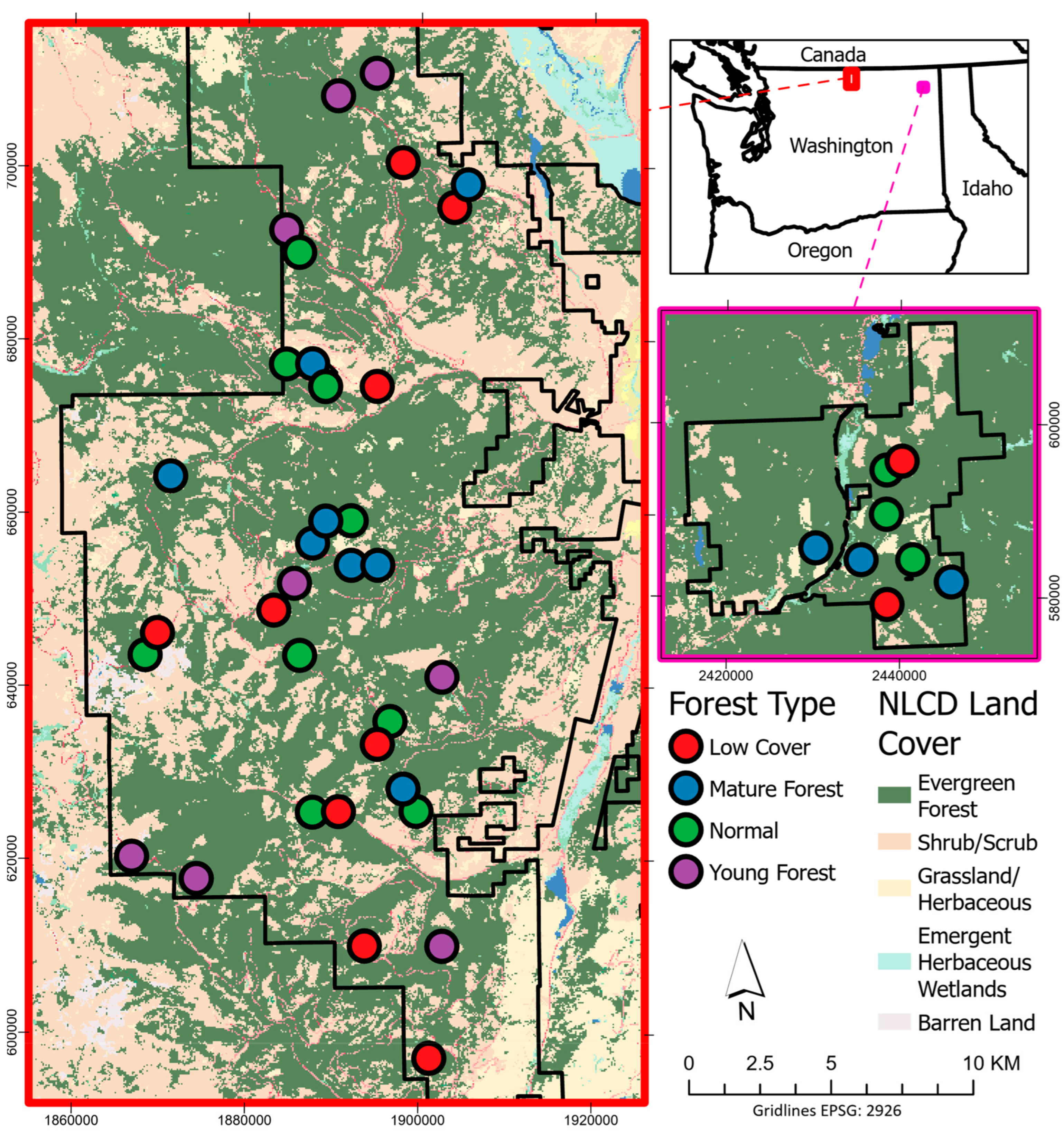
Figure 1. Map of study sites within the Loomis State Forest (red frame) and the Little Pend Oreille State Forest (pink frame). A total of 42 sites were sampled, with each site consisting of 4 TLS scan plots (168 plots total). Land cover classification from the National Land Cover Database was added to provide vegetation cover context.
Remotesensing 15 04434 g001
Figure 2. Diagram of TLS scanning locations and target spheres used for co-registration of the scans. Each site had 4 TLS scans (plots). The oblong shape of the exterior sphere and scan locations is because precise placement was often not possible due to vegetation occlusion.
Remotesensing 15 04434 g002
Figure 3. A 2D depth map of a TLS scan. This is a 2D representation of the full 360° scan, i.e., the left and right of the image are the same location in space. The wave-like contour of the land in the image is actually looking uphill (the high point on the left), and downhill (the low point on the right). All points that returned more than 10 m from the scanner are colored green. The ground level at 10 m is determined and a digital cover board (DCB) is placed, represented here by the points colored as grey scale.
Remotesensing 15 04434 g003
Figure 4. The dimensions of the view area of an object 2 m-tall and 10 m away from the TLS. The number of pixels within the depth raster representing 2 m is calculated by dividing the angular view (11.42°) by the scan angle increment (0.035°).
Remotesensing 15 04434 g004
Figure 5. A depth raster of a scan with all pixels further than 15 m colored green. The down-sampled pixel ribbon in the image (outlined in magenta) represents a series of 2 m × 0.3 m cover boards surrounding the central viewpoint at 15 m distance and 1.5 m above ground. A clear cover board as defined by the lynx survey protocols would be the bottom two cells in the line, all colored green.
Remotesensing 15 04434 g005
Figure 6. A voxelized and normalized TLS point cloud (left) with each point representing the centroid of a 10 cm cube. A voxel summary model (right) where each 0.5 m-resolution cube is colored by the number of occupied 10 cm voxels contained within it.
Remotesensing 15 04434 g006
Figure 7. Normalized ALS point cloud with the ground, 0.5 m above the ground, and 2 m above the ground, denoted with red lines. These lines illustrate the subdivisions of the ALS point cloud that were used for ALS metric generation. First and last return sub-selections were also created for ALS metric generation.
Remotesensing 15 04434 g007
Figure 8. The top four contributors to PC axes 1 and 2 with their absolute value of contribution amongst the 42 metrics reported. Seven of the eight metrics were products of voxelization, with only one being a digital cover board metric.
Remotesensing 15 04434 g008
Figure 9. The PCA plot of the TLS metrics. Points are colored by TLS digital cover board metrics considering high cover to be a plot where only 10% of the digital cover board pixels are visible.
Remotesensing 15 04434 g009
Figure 10. The relative importance of each of our 5 ALS model inputs for our final xgboost model. The final model had a testing accuracy of 85% with the two-class ordinal data of high cover and low cover being determined by the TLS DCB method.
Remotesensing 15 04434 g010
Figure 11. The xgboost model output for the Loomis State Forest. Low- and high-cover categories were created using the machine-learning approach with an 85% accuracy. The no-cover class included areas that had no ALS returns over 2 m. This map was derived using 2016 ALS data.
Remotesensing 15 04434 g011
Table 1. Summary table of the metrics derived from the terrestrial lidar point clouds. In total, 42 metrics were created from the digital cover board (DCB) depth maps and voxelization approaches.
TLS METRICS
10 M DCBTotal percentage of cover, number of pixels, percentage of cover within 10 m, and mean distance and standard deviation of all pixels and cover pixels at 10 m (7 of the 42 metrics).
15 M DCBPercentage of cover within 15 m per down-sampled pixel, percentage of cover within 15 m per vertical column of pixels, percentage of vertical columns with no cover, and mean distance and standard deviation of all pixels and cover pixels at 15 m (8 of the 42 metrics).
VOXELIZATIONTotal count of 10 cm voxels per 0.5 m height stratum, mean count of 10 cm voxels per 0.5 m cube, and count of 0.5 m cubes with 1 or more 10 cm voxels per height stratum (27 of the 42 metrics).
Table 2. Summary table of the metrics derived from the airborne lidar point clouds. In total, 286 metrics were created from the ALS data.
ALS METRICS
POINTS USEDAll points, only first returns, only last returns, all points < 2 m in height, and points > 0.5 m and <2 m in height (five groups of points).
Z AND INTENSITY METRICSCount, sum, max, mean, standard deviation, skew, kurtosis, percentage above mean, 19 height percentiles (5th to 95th percentile), and mean intensity at height percentiles (47 per group, 235 total).
RATIOSCPR for each point group (9 per group, 45 total), and ORD and NRD (6 total).
Disclaimer/Publisher’s Note: The statements, opinions and data contained in all publications are solely those of the individual author(s) and contributor(s) and not of MDPI and/or the editor(s). MDPI and/or the editor(s) disclaim responsibility for any injury to people or property resulting from any ideas, methods, instructions or products referred to in the content.