
Absolute Radiometric Calibration of ZY3-02 Satellite Multispectral Imager Based on Irradiance-Based Method


Abstract
:1. Introduction
2. Materials and Methods
2.1. ZY3-02 Satellite Background
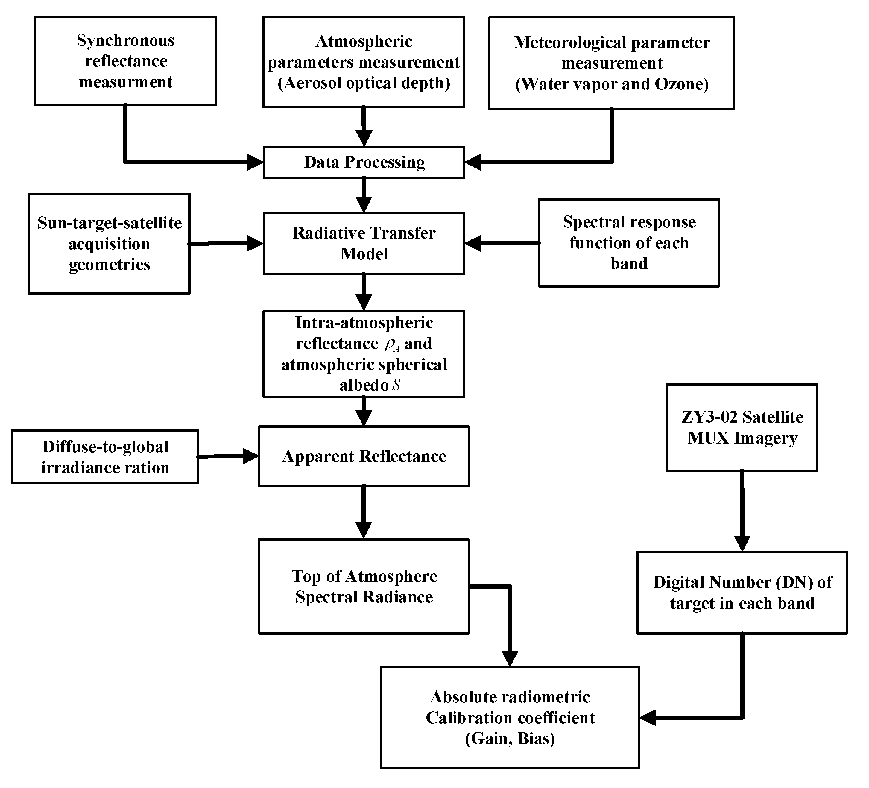
2.2. Irradiance-Based Absolute Radiometric Calibration Method
2.3. The Vicarious Radiometric Calibration Campaign
2.4. Synchronous Reflectance and Atmospheric Parameters Measurements
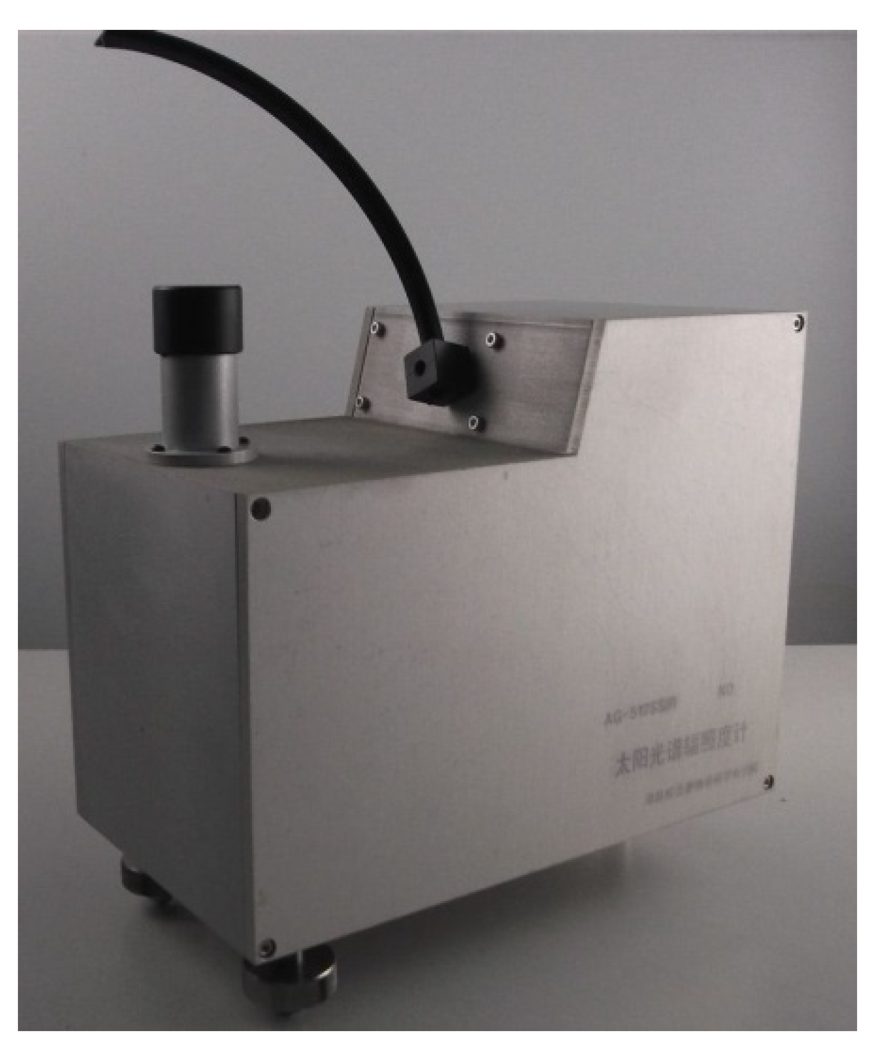
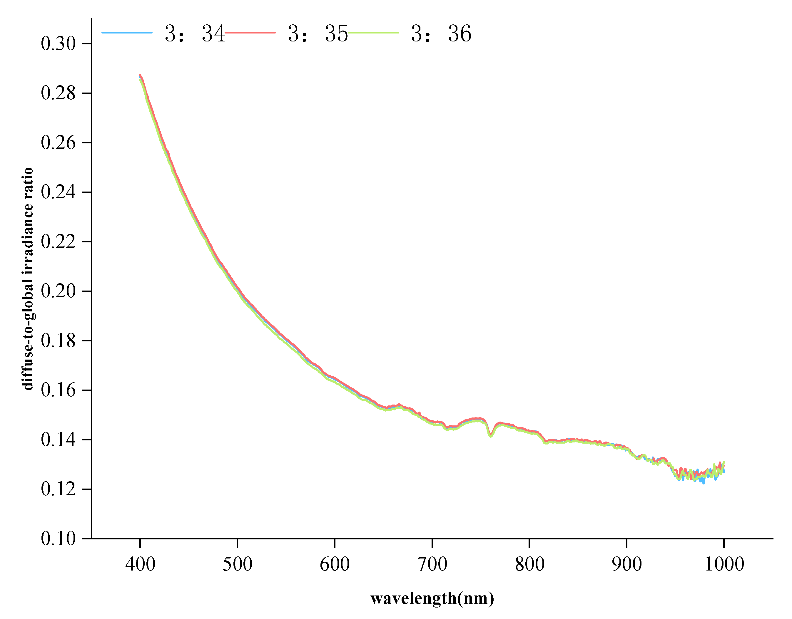
2.5. Measurement of Diffuse-to-Global Irradiance Ratio
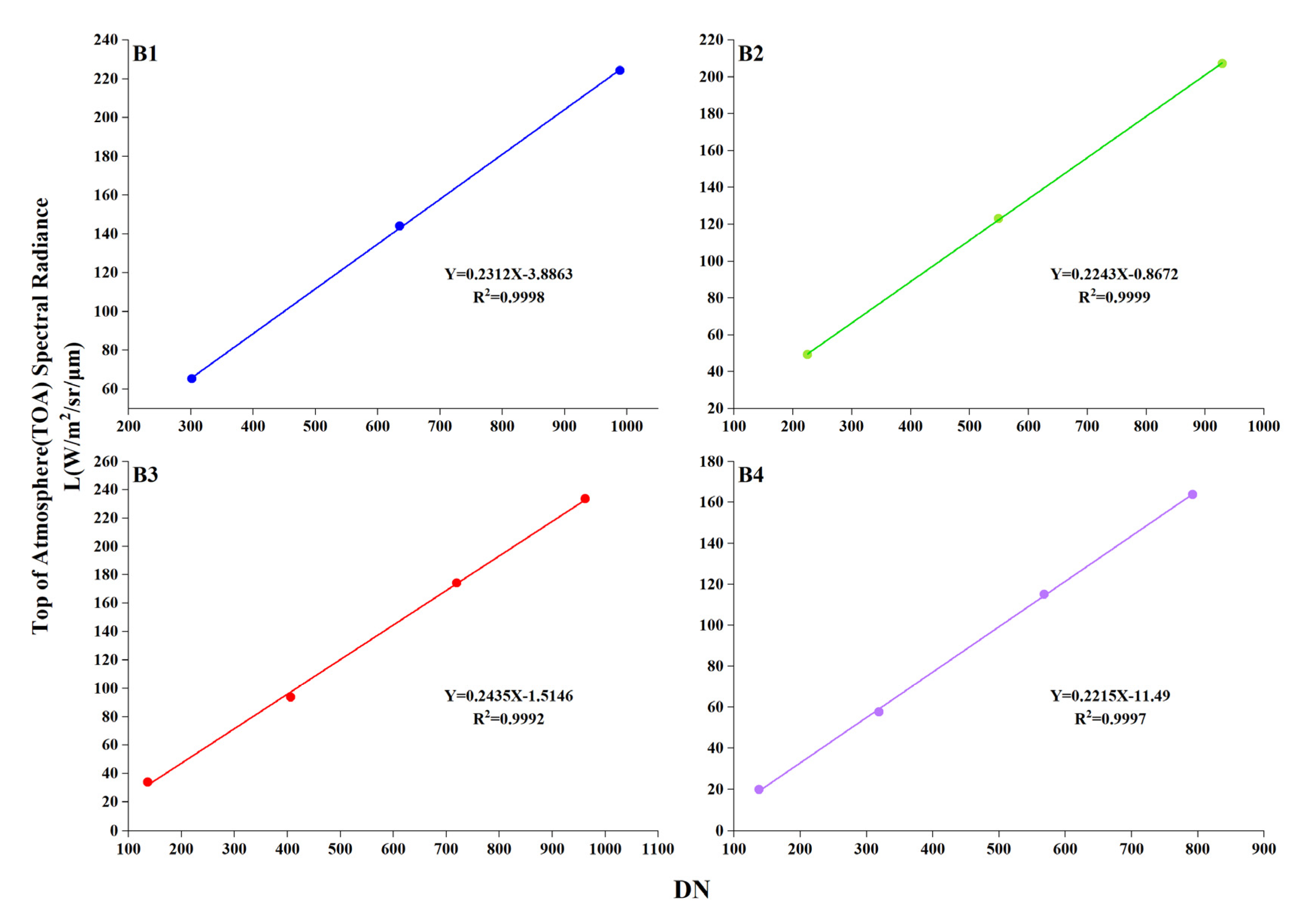
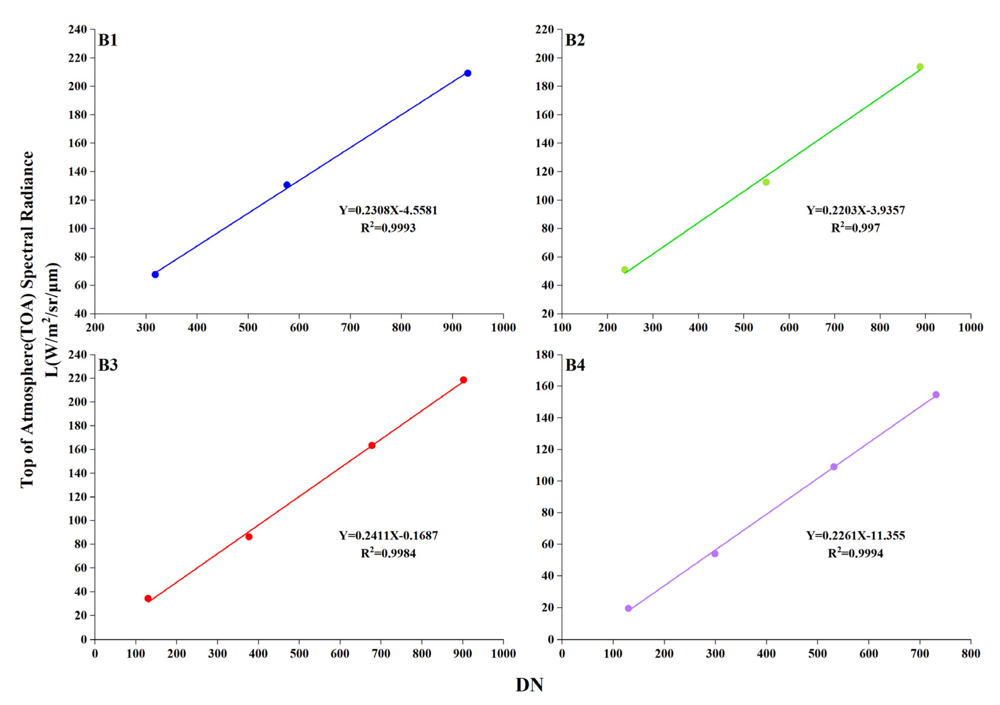
3. Radiometric Calibration Results
4. Uncertainty Analysis
4.1. Uncertainty Analysis of the Reflectance-Based Method
4.2. Uncertainty Analysis of the Irradiance-Based Method
5. Comparison of TOA Radiance Predicted by Reflectance-Based and Irradiance-Based Method
6. Conclusions
Author Contributions
Funding
Institutional Review Board Statement
Informed Consent Statement
Data Availability Statement
Conflicts of Interest
References
- Thome, K.J. Absolute Radiometric Calibration of Landsat 7 ETM+ Using the Reflectance-Based Method. Remote Sens. Environ. 2001, 78, 27–38. [Google Scholar] [CrossRef]
- Dinguirard, M.; Slater, P.N. Calibration of Space-Multispectral Imaging Sensors: A Review. Remote Sens. Environ. 1999, 68, 194–205. [Google Scholar] [CrossRef]
- Biggar, S.F.; Dinguirard, M.C.; Gellman, G.I.; Henry, P.; Jackson, R.D.; Moran, M.S.; Slater, P.N. Radiometric Calibration of SPOT 2 HRV-a Comparison of Three Methods. Proc. SPIE 1991, 1493, 155–162. [Google Scholar]
- Gao, H.L.; Gu, X.F.; Yu, T. The Research Overview on Visible and Near-infrared Channels Radiometric Calibration of Space-borne Optical Remote Sensors. Remote Sens. Inf. 2010, 4, 12. [Google Scholar]
- Frouin, R.; Gautier, C. Calibration of NOAA-7 AVHRR, GOES-5, and GOES-6 VISSR/VAS solar channels. Remote Sens. Environ. 1987, 22, 73–101. [Google Scholar] [CrossRef] [Green Version]
- Pagnutti, M.; Ryan, R.E.; Kelly, M.; Holekamp, K.; Zanoni, V.; Thome, K.; Schiller, S. Radiometric characterization of IKONOS multispectral imagery. Remote Sens. Environ. 2003, 88, 53–68. [Google Scholar] [CrossRef] [Green Version]
- Xiong, X.; Barnes, W.; Xie, X.; Salomonson, V. On-orbit performance of Aqua MODIS on-board calibrators. Proc. SPIE 2005, 5978, 75–80. [Google Scholar]
- Ponzoni, F.J.; Junior, J.Z.; Lamparelli, R. In-flight absolute calibration of the CBERS-2 CCD sensor data. An. Acad. Bras. Ciênc. 2008, 80, 799–804. [Google Scholar] [CrossRef] [PubMed] [Green Version]
- Hu, X.; Liu, J.; Sun, L.; Rong, Z.; Li, Y.; Zhang, Y.; Zheng, Z.; Wu, R.; Zhang, L.; Gu, X. Characterization of CRCS Dunhuang test site and vicarious calibration utilization for Fengyun (FY) series sensors. Can. J. Remote Sens. 2010, 36, 566–582. [Google Scholar] [CrossRef]
- Naughton, D.; Brunn, A.; Czapla-Myers, J.; Douglass, S.; Thiele, M.; Weichelt, H.; Oxfort, M. Absolute radiometric calibration of the RapidEye multispectral imager using the reflectance-based vicarious calibration method. J. Appl. Remote Sens. 2011, 5, 3544. [Google Scholar] [CrossRef]
- Tang, H.; Xie, J.; Tang, X.; Chen, W.; Li, Q. On-Orbit Radiometric Performance of GF-7 Satellite Multispectral Imagery. Remote Sens. 2022, 14, 886. [Google Scholar] [CrossRef]
- Tang, H.; Xie, J.; Tang, X.; Chen, W.; Li, Q. On-Orbit Absolute Radiometric Calibration and Validation of ZY3-02 Satellite Multispectral Sensor. Sensors 2022, 22, 2066. [Google Scholar] [CrossRef] [PubMed]
- Bouvet, M.; Thome, K.; Berthelot, B.; Bialek, A.; Czapla-Myers, J.; Fox, N.P.; Goryl, P.; Henry, P.; Ma, L.; Marcq, S.; et al. RadCalNet: A Radiometric Calibration Network for Earth Observing Imagers Operating in the Visible to Shortwave Infrared Spectral Range. Remote Sens. 2019, 11, 2401. [Google Scholar] [CrossRef] [Green Version]
- Li, C.R.; Ma, L.L.; Tang, L.L.; Gao, C.X.; Qian, Y.G.; Wang, N.; Wang, X.H. A comprehensive calibration site for high resolution remote sensors dedicated to quantitative remote sensing and its applications. Natl. Remote Sens. Bull. 2021, 25, 198–219. [Google Scholar]
- Yeom, J.-M.; Hwang, J.; Jung, J.-H.; Lee, K.-H.; Lee, C.-S. Initial Radiometric Characteristics of KOMPSAT-3A Multispectral Imagery Using the 6S Radiative Transfer Model, Well-Known Radiometric Tarps, and MFRSR Measurements. Remote Sens. 2017, 9, 130. [Google Scholar] [CrossRef] [Green Version]


| ZY3-02 Satellite | Detailed Information |
|---|---|
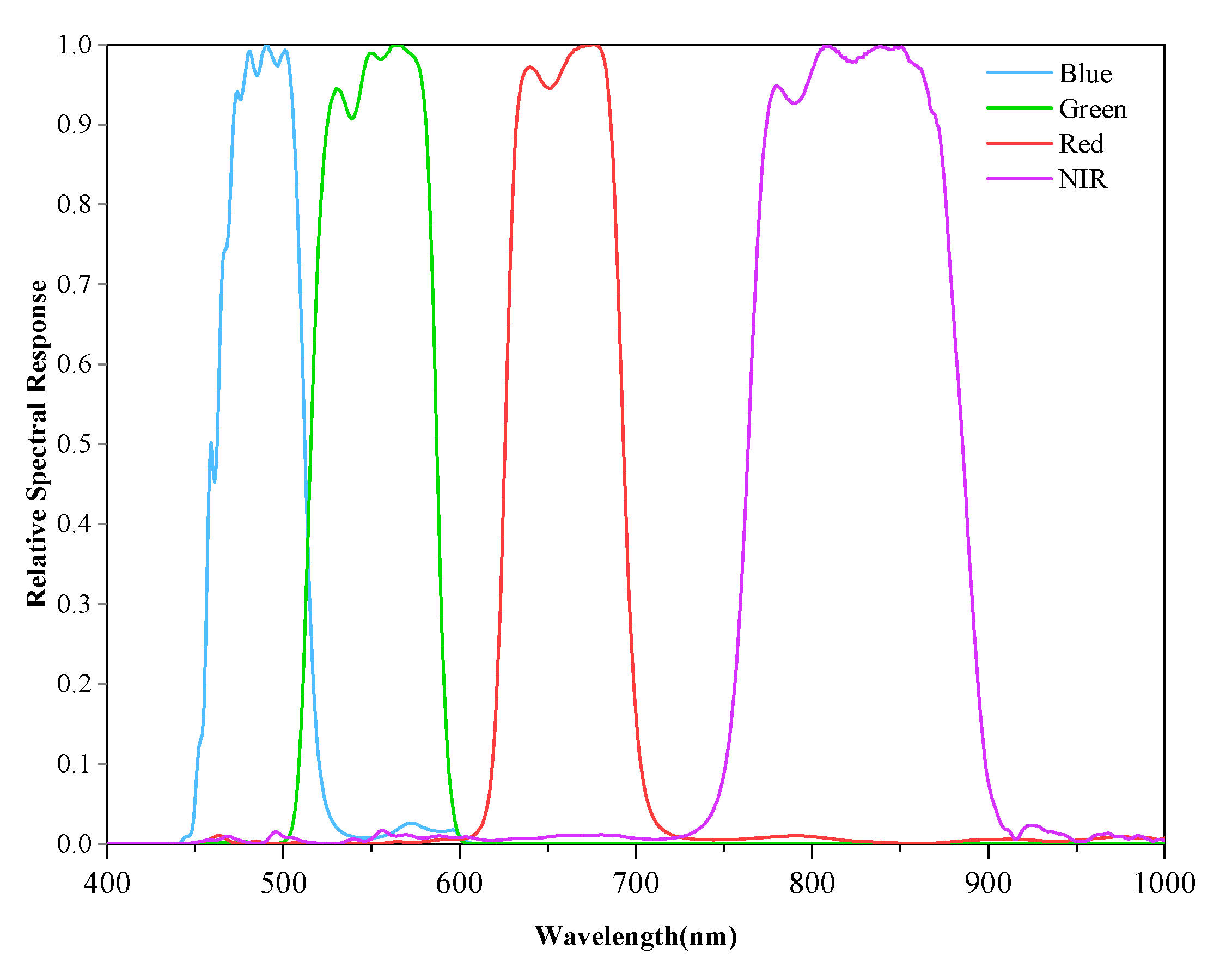
| Spectral Bands | Panchromatic band: 0.45–0.9 um Blue band: 0.45–0.52 um Green band: 0.52–0.59 um Red band: 0.63–0.69 um NIR band: 0.77–0.89 um |
| Spatial resolution | Panchromatic band: nadir-view: 2.1 m (GSD) |
| forward-view (+22°): 2.5 m (GSD) | |
| backward-view (−22°): 2.5 m (GSD) | |
| Multispectral: nadir-view: 5.8 m (GSD) | |
| Radiometric Resolution | 10 bits |
| Swath width | 51 km |
| Site | Date | Satellite Overpass Time (UTC) | Solar Zenith Angle | Solar Azimuth Angle | Viewing Zenith Angle | Viewing Azimuth Angle |
|---|---|---|---|---|---|---|
| Baotou calibration site | 28 June 2018 | 03:35:22 | 20.497 | 146.015 | 5.872 | 208.995 |
| 3 July 2018 | 03:39:18 | 21.573 | 145.360 | −1.394 | 151.594 |
| Atmospheric Parameters Measured | Measurement Results | |
|---|---|---|
| Date | 28 June 2018 | 3 July 2018 |
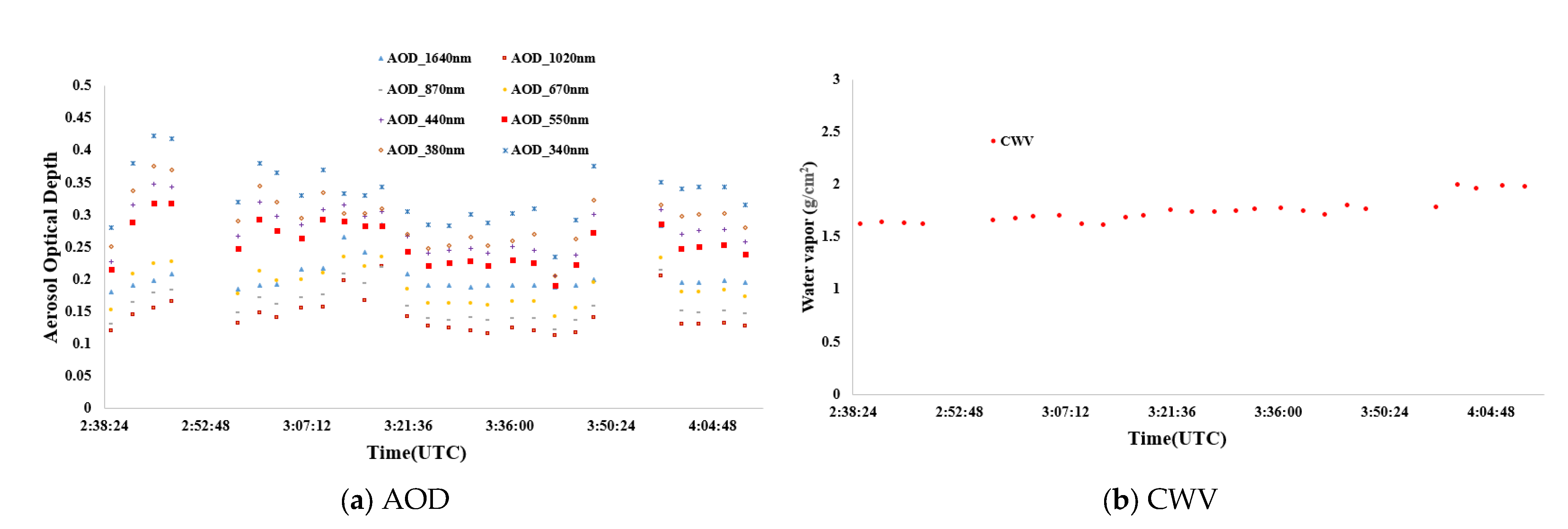
| AOD @ 550 nm | 0.2655 | 0.0760 |
| CWV | 1.2351 g/cm2 | 0.8132 g/cm2 |
| Time (UTM) | Direction | Diffuse-to-Global Irradiance Ratio | |||
|---|---|---|---|---|---|
| MUX-B1 | MUX-B2 | MUX-B3 | MUX-B4 | ||
| 03:35, 28 June 2018 | At solar zenith angle | 0.2069 | 0.1792 | 0.1534 | 0.1419 |
| At viewing zenith angle | 0.1802 | 0.1569 | 0.1345 | 0.1227 | |
| 03:38, 3 July 2018 | At solar zenith angle | 0.1625 | 0.1218 | 0.0978 | 0.0946 |
| At viewing zenith angle | 0.1376 | 0.0997 | 0.0767 | 0.0705 | |
| Coefficient | Irradiance-Based | Reflectance-Based | Official Coefficient | ||||||
|---|---|---|---|---|---|---|---|---|---|
| 3 July 2018 | 28 June 2018 | 3 July 2018 | 28 June 2018 | ||||||
| Band | Coefficients A | Coefficients B | Coefficients C | Coefficients D | Coefficients E | ||||
| Gain | Bias | Gain | Bias | Gain | Bias | Gain | Bias | Gain | |
| MUX-B1 | 0.2312 | −3.886 | 0.2308 | −4.558 | 0.2241 | −2.223 | 0.2102 | −6.887 | 0.2295 |
| MUX-B2 | 0.2243 | −0.867 | 0.2203 | −3.936 | 0.2192 | −0.333 | 0.2018 | −5.039 | 0.2212 |
| MUX-B3 | 0.2435 | −1.515 | 0.2411 | −0.1687 | 0.2368 | −1.361 | 0.2176 | −1.971 | 0.2413 |
| MUX-B4 | 0.2215 | −11.49 | 0.2261 | −11.355 | 0.2186 | −11.167 | 0.2026 | −11.478 | 0.2110 |
| Source of Uncertainty | Accuracy % | TOA Radiance Uncertainty % |
|---|---|---|
| Surface reflectance measurement | 2.0% | 2.0% |
| Lambertian assumption of targets | 2.0% | 2.0% |
| Aerosol optical depth | 0.5% | |
| Total columnar water vapor | 0.5% | |
| Aerosol type assumption | 4.0% | |
| MODTRAN 6.0 Radiative transfer | 2.0% | 2.0% |
| Overall Uncertainty | 5.68% |
| Source of Uncertainty | Accuracy % | TOA Radiance Uncertainty % |
|---|---|---|
| Surface reflectance measurement | 2.0% | 2.0% |
| Lambertian assumption of targets | 2.0% | 2.0% |
| Total columnar water vapor | 0.5% | |
| Aerosol optical depth | 0.5% | |
| The diffuse-to-global irradiance ratio | 2.0% | |
| MODTRAN 6.0 Radiative transfer | 2.0% | 2.0% |
| Overall Uncertainty | 4.06% |
| Target | Radiance | MUX-B1 | MUX-B3 | MUX-B3 | MUX-B 4 |
|---|---|---|---|---|---|
| 5% tarp | Calculated TOA | 65.822 | 50.012 | 35.426 | 20.012 |
| Irradiance-based | 65.341 | 49.206 | 34.852 | 19.895 | |
| Difference 1 | −0.73% | −1.61% | −1.62% | −0.58% | |
| Reflectance-based | 64.526 | 48.505 | 33.342 | 19.61 | |
| Difference 2 | −1.97% | −3.01% | −5.88% | −2.01% | |
| 20% tarp | Calculated TOA | 146.098 | 127.626 | 98.755 | 58.264 |
| Irradiance-based | 144.081 | 123.031 | 93.861 | 57.684 | |
| Difference 1 | −1.38% | −3.60% | −4.96% | −1.00% | |
| Reflectance-based | 141.854 | 120.828 | 90.681 | 55.531 | |
| Difference 2 | −2.90% | −5.33% | −8.18% | −4.69% | |
| 40% tarp | Calculated TOA | 229.874 | 214.558 | 177.232 | 117.828 |
| Irradiance-based | 224.211 | 207.192 | 174.124 | 115.071 | |
| Difference 1 | −2.46% | −3.43% | −1.75% | −2.34% | |
| Reflectance-based | 218.521 | 201.485 | 168.319 | 110.08 | |
| Difference 2 | −4.94% | −6.09% | −5.03% | −6.58% | |
| Red tarp | Calculated TOA | 91.283 | 72.367 | 131.224 | 94.394 |
| Irradiance-based | 90.049 | 70.925 | 127.276 | 90.788 | |
| Difference 1 | −1.35% | −1.99% | −3.01% | −3.82% | |
| Reflectance-based | 87.426 | 68.377 | 123.261 | 88.734 | |
| Difference 2 | −4.23% | −5.51% | −6.07% | −6.00% | |
| Blue tarp | Calculated TOA | 223.765 | 133.622 | 97.872 | 145.121 |
| Irradiance-based | 218.969 | 129.619 | 94.397 | 143.698 | |
| Difference 1 | −2.14% | −3.00% | −3.55% | −0.98% | |
| Reflectance-based | 216.247 | 126.458 | 92.22 | 138.771 | |
| Difference 2 | −3.36% | −5.36% | −5.77% | −4.38% |
| Target | Radiance | MUX-B1 | MUX-B3 | MUX-B3 | MUX-B 4 |
|---|---|---|---|---|---|
| 5% tarp | Calculated TOA | 68.726 | 51.306 | 36.013 | 20.023 |
| Irradiance-based | 67.59 | 50.85 | 34.225 | 19.489 | |
| Difference 1 | −1.65% | −0.89% | −4.96% | −2.67% | |
| Reflectance-based | 61.836 | 46.904 | 30.281 | 16.517 | |
| Difference 2 | −10.03% | −8.58% | −15.92% | −17.51% | |
| 20% tarp | Calculated TOA | 134.76 | 115.368 | 88.776 | 56.212 |
| Irradiance-based | 130.538 | 112.446 | 86.215 | 54.141 | |
| Difference 1 | −3.13% | −2.53% | −2.88% | −3.68% | |
| Reflectance-based | 123.162 | 105.054 | 81.214 | 50.573 | |
| Difference 2 | −8.61% | −8.94% | −8.52% | −10.03% | |
| 40% tarp | Calculated TOA | 214.568 | 196.655 | 167.322 | 111.497 |
| Irradiance-based | 209.178 | 193.818 | 163.4 | 109.059 | |
| Difference 1 | −2.51% | −1.44% | −2.34% | −2.19% | |
| Reflectance-based | 197.551 | 182.289 | 155.642 | 103.456 | |
| Difference 2 | −7.93% | −7.31% | −6.98% | −7.21% | |
| Red tarp | Calculated TOA | 86.965 | 67.396 | 116.577 | 84.146 |
| Irradiance-based | 84.997 | 64.606 | 113.47 | 80.395 | |
| Difference 1 | −2.26% | −4.14% | −2.67% | −4.46% | |
| Reflectance-based | 77.812 | 59.349 | 105.871 | 75.345 | |
| Difference 2 | −10.52% | −11.94% | −9.18% | −10.46% | |
| Blue tarp | Calculated TOA | 213.335 | 128.672 | 89.423 | 133.984 |
| Irradiance-based | 205.622 | 122.945 | 85.249 | 128.179 | |
| Difference 1 | −3.62% | −4.45% | −4.67% | −4.33% | |
| Reflectance-based | 191.101 | 114.291 | 78.266 | 120.191 | |
| Difference 2 | −10.42% | −11.18% | −12.48% | −10.29% |
Disclaimer/Publisher’s Note: The statements, opinions and data contained in all publications are solely those of the individual author(s) and contributor(s) and not of MDPI and/or the editor(s). MDPI and/or the editor(s) disclaim responsibility for any injury to people or property resulting from any ideas, methods, instructions or products referred to in the content. |
© 2023 by the authors. Licensee MDPI, Basel, Switzerland. This article is an open access article distributed under the terms and conditions of the Creative Commons Attribution (CC BY) license (https://creativecommons.org/licenses/by/4.0/).
Share and Cite
Tang, H.; Xie, J.; Chen, W.; Zhang, H.; Wang, H. Absolute Radiometric Calibration of ZY3-02 Satellite Multispectral Imager Based on Irradiance-Based Method. Remote Sens. 2023, 15, 448. https://doi.org/10.3390/rs15020448
Tang H, Xie J, Chen W, Zhang H, Wang H. Absolute Radiometric Calibration of ZY3-02 Satellite Multispectral Imager Based on Irradiance-Based Method. Remote Sensing. 2023; 15(2):448. https://doi.org/10.3390/rs15020448
Chicago/Turabian StyleTang, Hongzhao, Junfeng Xie, Wei Chen, Honggeng Zhang, and Hengyang Wang. 2023. "Absolute Radiometric Calibration of ZY3-02 Satellite Multispectral Imager Based on Irradiance-Based Method" Remote Sensing 15, no. 2: 448. https://doi.org/10.3390/rs15020448