Communication

Imaging Simulation Method for Novel Rotating Synthetic Aperture System Based on Conditional Convolutional Neural Network

1
Research Center for Space Optical Engineering, Harbin Institute of Technology, Harbin 150001, China
2
Foreign Studies College of Northeastern University, Shenyang 110001, China
*
Author to whom correspondence should be addressed.
Remote Sens. 2023, 15(3), 688; https://doi.org/10.3390/rs15030688
Submission received: 16 December 2022 / Revised: 16 January 2023 / Accepted: 21 January 2023 / Published: 24 January 2023
(This article belongs to the Special Issue Machine Learning Methods Applied to Optical Satellite Images)

Abstract

:
The novel rotating synthetic aperture (RSA) is a new optical imaging system that uses the method of rotating the rectangular primary mirror for dynamic imaging. It has the advantage of being lightweight, with no need for splicing and real-time surface shape maintenance on orbit. The novel imaging method leads to complex image quality degradation characteristics. Therefore, it is vital to use the image quality improvement method to restore and improve the image quality to meet the application requirements. For the RSA system, a new system that has not been applied in orbit, it is difficult to construct suitable large datasets. Therefore, it is necessary to study and establish the dynamic imaging characteristic model of the RSA system, and on this basis provide data support for the corresponding image super resolution and restoration method through simulation. In this paper, we first analyze the imaging characteristics and mathematically model the rectangular rotary pupil of the RSA system. On this basis, combined with the analysis of the physical interpretation of the blur kernel, we find that the optimal blur kernel is not the point spread function (PSF) of the imaging system. Therefore, the simulation method of convolving the input image directly with the PSF is flawed. Furthermore, the weights of a convolutional neural network (CNN) are the same for each input. This means that the normal convolutional layer is not only difficult to accurately estimate the time-varying blur kernel, but also difficult to adapt to the change in the length–width ratio of the primary mirror. To that end, we propose a blur kernel estimation conditional convolutional neural network (CCNN) that is equivalent to multiple normal CNNs. We extend the CNN to a conditional model by taking an encoding as an additional input and using conditionally parameterized convolutions instead of normal convolutions. The CCNN can simulate the imaging characteristics of the rectangular pupil with different length–width ratios and different rotation angles in a controllable manner. The results of semi-physical experiments show that the proposed simulation method achieves a satisfactory performance, which can provide data and theoretical support for the image restoration and super-resolution method of the RSA system.

1. Introduction

The geostationary orbit optical remote sensing satellite can continuously obtain the remote sensing image of a specific position, which has the incomparable time resolution advantage of low-orbit satellites; therefore, it has always been the focus of remote sensing research [1,2,3,4,5]. Since the orbital altitude of the geostationary orbit optical remote sensing satellite is at least 50 times that of the low-orbit satellite, the imaging capability of the geostationary orbit satellite is much higher than that of the low-orbit satellite to achieve the same image resolution and imaging quality. In order to meet the requirements of a large aperture and being lightweight, imaging technologies of high-orbit remote sensing satellites based on different manufacturing methods have been proposed. These mainly include the imaging techniques of sparse aperture, membrane diffraction, and rotating synthetic aperture (RSA). The sparse aperture technique divides a large aperture mirror into many small aperture mirrors and folds them together. After launching into orbit, the system components unfold and splice each other in turn. Due to the small size of the sub-mirror, the difficulty of making the sub-mirror is greatly reduced compared with the large aperture single primary mirror, which improves the engineering realizability of the system. However, the co-phasing accuracy of each sub-mirror in the system needs to be guaranteed, which puts forward higher requirements for the mechanical control system of satellites. The membrane diffraction imaging technology uses a thin-film material as the diffraction primary mirror, the overall mass of the system is light, and the surface accuracy of the mirror body does not need to be too high, thus reducing the difficulty and cost of production. However, due to the restriction of the diffraction principle, the imaging band of the membrane diffraction imaging system is relatively narrow, so it cannot be used for multi-band imaging. The RSA imaging technology uses a rectangular primary mirror to reduce the weight of the system and the difficulty of production. In the imaging process of the system, the primary mirror rotates constantly, so that the RSA system can achieve equivalent long-side aperture imaging in different rotation angles, and higher imaging quality will time-share coverage of all directions of the image sequence. It has the advantage of being lightweight, with no need for splicing and real-time surface shape maintenance on orbit [6]. Considering the manufacturing method, expected application efficiency, and satellite vehicle requirements, this novel system has great advantages over other high-orbit remote sensing satellite imaging technologies, and it is a promising development direction of geostationary orbit optical remote sensing satellites [7,8,9,10].
In the process of time series imaging of the RSA imaging system, the rotation of the rectangular mirror makes the image quality change periodically. The quality of the acquired images in the direction of the short side of the primary mirror is obviously lower than that in the direction of the long side [11]. In addition, as shown in Figure 1, due to the coupling of the rotation error of the primary mirror, satellite platform vibration, optical system, detector photoelectric conversion and sampling, electronic system, and other factors, the quality of two frames with the same rotation angle is not the same. Therefore, the physical mechanism of the RSA system must be combined to improve the imaging quality to meet the application requirements.
For the past few years, deep-learning-based image restoration and super-resolution methods have achieved remarkable results [12,13,14,15,16,17,18,19,20]. However, this kind of method requires a lot of data to complete the model training. For the RSA system, which has not been implemented in orbit yet, it is difficult to construct suitable training datasets based on real images. Furthermore, most image super-resolution and restoration methods assume that the low-quality input image is obtained by downsampling the unknown high-quality image with a known blur kernel and the kernel is usually assumed to be the system’s point spread function (PSF) [21,22,23,24,25]. However, through the analysis of the relations between the discrete-domain low-quality image, the discrete-domain high-quality image, and the continuous-domain real-world scene, that is, the physical interpretation of the blur kernel, we find that the optimal blur kernel is not a simple discretization nor an approximation of the PSF, although it is associated with the PSF [25]. This means that the simulation method of convolving the input image directly with the RSA system’s PSF is flawed. Therefore, it is of great significance to establish a targeted image simulation method based on the temporal periodicity and spatial asymmetry for the RSA system, so as to provide data support for the corresponding image quality improvement method. For this purpose, we first mathematically model the rectangular rotary pupil and study the spatial distribution and temporal variation of its PSF. Then, we propose a blur kernel estimation conditional convolutional neural network that is adaptive to length–width ratio and angle. By taking an encoding related to the length–width ratio and the rotation angle of the rectangular mirror, the convolutional neural network (CNN) can be extended to a conditional model. The proposed conditional convolutional neural network (CCNN) can estimate specialized convolutional kernels for each input encoding, so that the influence of different length–width ratios and different angles of the rectangular mirror can be simulated in a controllable way.
This paper is structured as follows. In Section 2, we analyze the imaging characteristics of the rectangular rotary pupil. Then, we propose a novel method to simulate its characteristics based on the CCNN. In Section 3, we verify the effectiveness of the proposed simulation method through semi-physical imaging experiments. We also discuss the advantages of the proposed simulation method by comparing it with the simulation method which uses the imaging system’s PSF as the “blur kernel” based on the experimental results. Finally, we summarize the results in Section 4.

2. Imaging Simulation Method for the RSA System

2.1. Analysis of the Rectangular Rotary Pupil’s Imaging Characteristics

The RSA system is unique in that it uses a rectangular primary mirror to ensure a lightweight condition, which results in spatial asymmetry of the imaging quality. In addition, the dynamic imaging mode makes the degradation characteristics of the same spatial position different at different moments in the imaging process, resulting in the periodic change of imaging quality with time. In this section, the mathematical modeling of the rectangular pupil of the RSA system is carried out to analyze its imaging characteristics.
The amplitude spread function U ( x , y ) of the RSA system is the Fourier transform of the pupil function P ( ξ , η ) :
U ( x , y ) = F . T . { P ( ξ , η ) } = 1 λ z n = 1 N P ( ξ , η ) exp [ i k ( ξ n x + η n y z ) ] d ξ d η
where z is the focal length, λ is the wavelength, k = 2 π / λ is the wave number, and F.T.{} represents the Fourier transform.
From this, the PSF can be calculated, which is equal to the square of the modulus of the amplitude spread function:
P S F ( x , y ) = | U ( x , y ) | 2
The rectangular pupil is shown in Figure 2.
According to Figure 2, the rectangular pupil function P r e c t ( ξ , η , t ) at time t is:
P r e c t ( ξ , η , t ) = r e c t ( ξ cos ( w t + φ 0 ) η sin ( w t + φ 0 ) a ) r e c t ( ξ sin ( w t + φ 0 ) + η cos ( w t + φ 0 ) b )
The amplitude spread function U r e c t ( x , y , t ) is the Fourier transform of the pupil function:
U r e c t ( x , y , t ) = F . T . { P r e c t ( ξ , η , t ) } = a b b 2 b 2 a 2 a 2 r e c t ( ξ cos ( w t + φ 0 ) η sin ( w t + φ 0 ) a ) r e c t ( ξ sin ( w t + φ 0 ) + η cos ( w t + φ 0 ) b ) exp i k ( ξ x + η y z ) d ξ d η
Then, the point spread function P S F r e c t ( x , y , t ) can be calculated:
P S F r e c t ( x , y , t ) = | U r e c t ( x , y , t ) | 2 = a b sin c ( a ( x cos ( w t + φ 0 ) y sin ( w t + φ 0 ) ) ) × sin c ( b ( x sin ( w t + φ 0 ) + y cos ( w t + φ 0 ) ) )
where a is the length of the rectangular pupil, b is the width of the rectangular pupil, w is the rotation angular velocity, and w t + φ 0 is the rotation phase at time t.
According to (5), the PSF of different rotation angles of the system’s rectangular pupil is calculated as shown in Figure 3. As can be seen from the figure, the PSF is approximately elliptical in the case of ignoring the secondary diffraction effect. The shape of the ellipse is determined by the length–width ratio of the rectangle and the direction of the long axis corresponds to the direction of the short side [6].

2.2. Simulation of the Rectangular Rotary Pupil’s Imaging Characteristics

The simulation process of the rectangular rotary pupil’s imaging characteristics can be summarized as follows: take a high-quality image as input; use the kernel k related to the length–width ratio and the rotation angle of the pupil to operate the input image to simulate the degradation caused by the spatial asymmetric and time-varying pupil; and then obtain the simulated image. What is noteworthy is that the input of the simulation process is a digital image in the discrete domain rather than a scene in the continuous domain. In other words, the input high-quality image has undergone an imaging process of the optical system, as shown in Figure 4. The physical interpretation of the kernel k can be intuitively understood from Figure 4 as composed of two operations: deconvolution with b H followed by convolution with b L . Therefore, in contrast to the common belief, the optimal blur kernel is typically narrower than the PSF and, counter intuitively, it may assume negative values, a property not shared by the PSF [25]. Namely, the PSF is not the optimal blur kernel k because the blur kernel represents the degradation process from the high-quality input image to the low-quality output image. The PSF ignores the deconvolution process from the high-quality image to the continuous scene, and the convolution kernel b H of this process is often unknown. The authenticity of the simulation results is directly affected by the accuracy of the kernel, so the input image cannot be simply convoluted with the PSF of the RSA system’s pupil to simulate the image degradation process caused by the rectangular rotary pupil.
In addition, the spatial asymmetry and temporal periodicity of the RSA system’s pupil brings two difficulties to the simulation. On the one hand, some methods used to estimate the blur kernel k assume that the kernel can be estimated by relying on patch recurrence across scales of the input low-quality image. They also assume that the kernel which maximizes the similarity of recurring patches across scales of the low-quality image is also the optimal blur kernel between the low-quality image and the high-quality image [25,26]. This may be true for the high-low quality image pairs acquired by the imaging system with a round pupil. However, for the image simulation of the RSA system, the input is a high-quality image acquired by the imaging system with a round pupil. The recurring patches are obviously very different from the images obtained by the RSA system with a rectangular pupil. Namely, the recurrence of small image patches across scales is destroyed by the spatial asymmetry of the rectangular pupil. On the other hand, one fundamental assumption in the design of convolutional layers is that the same convolutional kernels are applied to every example in a dataset [27], which means the weights of a network are the same for each input. This also means that in using the normal convolutional layer, it is not only difficult to accurately estimate the time-varying blur kernel, but also difficult to adapt to the change of the length–width ratio of the primary mirror. Therefore, it is necessary to improve the CNN to estimate specialized convolutional kernels for each rotation angle and the length–width ratio of the primary mirror in the simulation process.
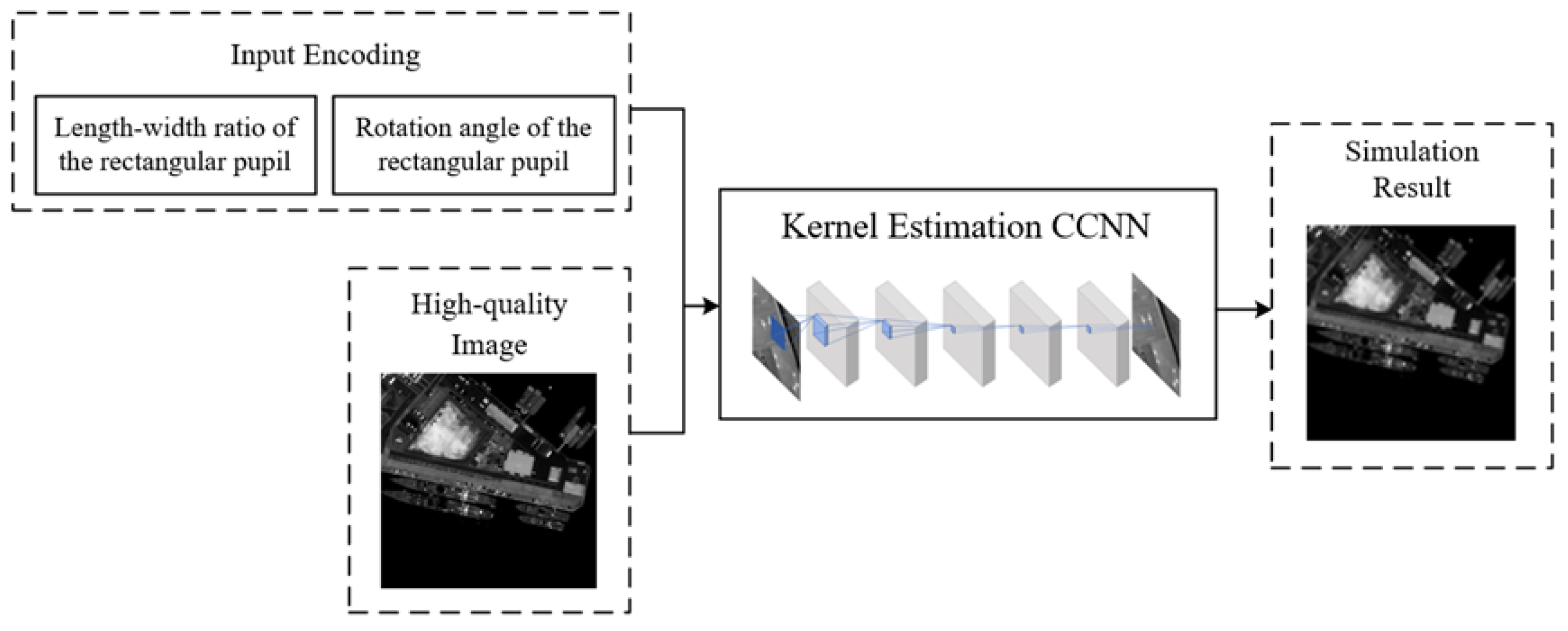
For this, inspired by the conditionally convolution (CondConv) [27] and CGAN [28], we propose the blur kernel estimation conditional convolutional neural network that is adaptive to length–width ratio and angle. The CCNN takes a high-quality image and the easily interpretable encoding related to the length–width ratio and the rotation angle of the primary mirror as inputs. We use five hidden conditional convolutional layers. As shown in Figure 5, the 6 convolution kernels are 7 × 7, 5 × 5, 3 × 3, 1 × 1, 1 × 1, and 1 × 1, respectively [29].
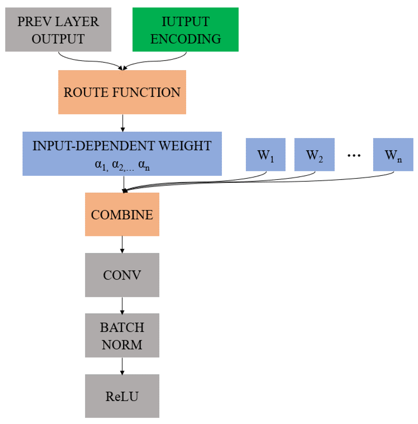
The convolutional kernel is computed as a function of the input in a conditional convolutional layer, as shown in Figure 6. Specifically, the conditionally convolution layer parameterizes the convolutional kernels as a linear combination of n experts [27]:
Output ( x ) = σ ( ( α 1 W 1 + + α n W n ) x )
where n is the number of experts, σ is an activation function, and each α i is an input-dependent scalar weight. We compute the scalar weights using a routing function with learned parameters.
In [27], Yang et al. compute the routing weights α i = r i ( x ) from the layer input in three steps: global average pooling, fully-connected layer, and Sigmoid activation. On this basis, we believe that not only a single convolutional layer but also the entire CNN can be extended to a conditional model if it is conditioned on some extra information. We can perform the conditioning by feeding extra information which is related to the rectangular mirror’s length–width ratio and rotation angle into the routing function as an additional input layer. The CCNN can meaningfully differentiate between inputs, so as to simulate the images taken by the primary mirror with different length–width ratios and different rotation angles.
We construct the input code as follows: for 1,2,…, 12, a total of 12 length–width ratios and 0°, 5°, …, 180°, a total of 36 rotation angles; we simply use two one-hot encodings (12 bits for length–width ratios and 36 bits for rotation angles) and concatenate them to become a 48-bit encoding as input. Then, the output after passing through a fully-connected neural network with Sigmoid activation and only one hidden layer is concatenated to the input of the original routing function in [27] as a new input vector. This vector is then used to calculate the scalar weight α by another fully-connected neural network with Sigmoid activation and only one hidden layer. According to [27], we set the hidden layer size of the two fully-connected neural networks to be the same as the dimension of their input. In addition, referring to the “baseline model” in [27], we compute new routing weights for each layer. A flowchart for the proposed imaging simulation method is shown in Figure 7.
Two points about the proposed CCNN are worth further elaboration:
First, different from the linear CNN used to estimate the blur kernel in [29], we propose the CCNN to more accurately simulate the image degradation caused by a rectangular pupil rather than explicitly extracting the blur kernel. The satellite platform in the orbit environment, detector, electronic system, and other factors will also affect the image quality. For image restoration and super resolution, it is of little significance to extract the kernel only related to the system’s pupil explicitly. Therefore, we retain the nonlinear activations to better simulate the blur kernel specific to the rotation angle and the length–width ratio of the pupil.
The second point is about the difference between the CondConv and channel attention [30]. Although the convolution operation processes the input in both the spatial domain and the channel domain dimensions, in essence, the information of the channel domain can be regarded as the hierarchical features (or information) of the original input, that is, the channel domain is the hierarchical diffusion of the spatial domain information. Convolution is essentially the extraction of spatial domain information, but in the process of cascading convolution, the spatial domain information is scattered in the channel domain. Therefore, instead of calculating the channel attention after the input image is operated with the nonspecific normal convolution kernel, we expect that the experts in CondConv can “independently” separate the influences of different length–width ratios and rotation angles according to the input encodings. We believe that CondConv can assign different weights to each convolution kernel and then simulate the “blur kernel” with different length–width ratios and rotation angles.

3. Experiments

3.1. Experimental Scheme

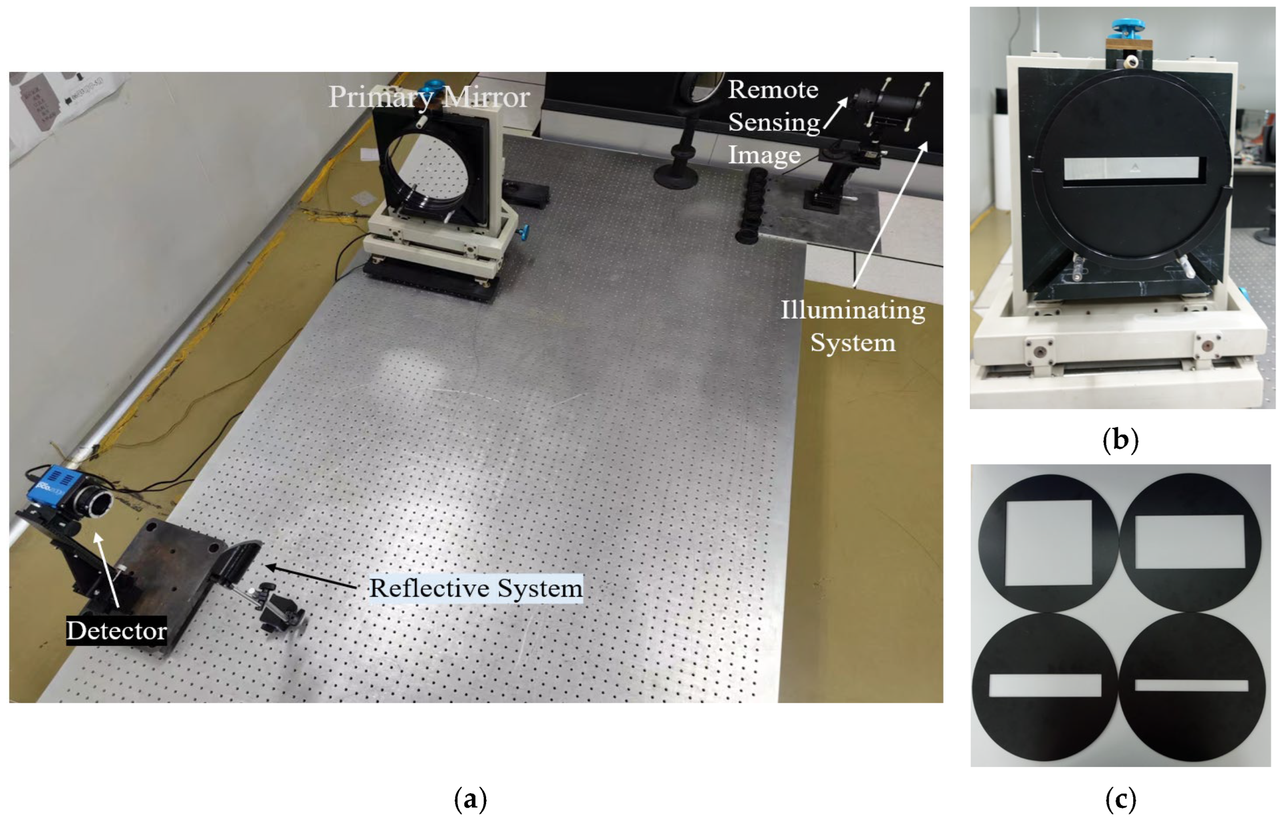
We verify the effectiveness of the proposed CCNN through laboratory semi-physical imaging experiments. We build an imaging experiment platform simulating the RSA system in the laboratory as shown in Figure 8. The platform uses a high-quality circular primary mirror with a removable and rotary rectangular entrance pupil optical element at its front end. Sampling, signal conversion, and noise effects are involved in the detector. Professional mapping equipment is used to produce high-resolution images as the target scenes. We use this imaging experiment platform to first image the target scene through the circular primary mirror and then we install the entrance pupil optical elements with different length–width ratios and rotate them at different angles to image the same target scene, so as to form high-low quality image pairs and build datasets for training and testing the proposed CCNN. Some target scenes are shown in Figure 9. Since the “high-quality image”, that is, the input of the CCNN is taken by the circular primary mirror, it can be considered that the effect of the detector, electronic system, and the rest of the optical system on the image degradation process has been included in the input image. Therefore, the effectiveness of the proposed simulation method can be verified by comparing the similarity degree between the simulation image and the real image taken when the entrance pupil optical element with the corresponding length–width ratio and rotation angle is installed. To further demonstrate the superiority of the proposed simulation method, as a comparison, we also objectively evaluate the results of a common simulation method (hereinafter referred to as the PSF-conv method), which directly convolves images taken by the circular primary mirror using the system’s PSF. The experimental process is shown in Figure 10.

3.2. Training Details

We implement the CCNN with the PyTorch framework and train it using an Nvidia RTX 2080 GPU. We use the Charbonnier penalty function as the loss: = S R 2 + ε 2 , where R represents the ground-truth image, S represents the simulation image, and ε is set to 1 × 10⁻³. We train the CCNN with Adam optimizer by setting β1 = 0.9 and β2 = 0.999. The learning rate is initialized as 2 × 10⁻⁴. We set the batch size to 16 and trained the model with 30 epochs.

3.3. Experimental Results and Discussion

Table 1 presents the quantitative evaluation of the simulation results of the proposed method and the PSF-conv method according to the image structural similarity (SSIM) [31] and the peak signal-to-noise ratio (PSNR).
SSIM is defined by:
S S I M ( R , S ) = ( 2 μ r μ s + c 1 ) ( 2 σ r s + c 2 ) ( μ r 2 + μ s 2 + c 1 ) ( σ r 2 + σ s 2 + c 2 )
where R represents the real image, S represents the simulation image, μ r and μ s are the mean of the simulation image and the simulation image, respectively, σ r 2 and σ s 2 are the variance of the real image and the simulation image respectively, and c 1 and c 2 are constants that are used to maintain stability. The value range of SSIM is [0, 1]; the higher the similarity between the two images, the closer the value of the SSIM is to 1.
PSNR is defined by:
P S N R ( R , S ) = 10 lg ( 2 k 1 ) 2 M 1 M 2 x = 1 M 1 y = 1 M 2 [ R ( x , y ) S ( x , y ) ] 2
where R represents the real image, S represents the simulation image, M 1 and M 2 are, respectively, the length and width of the image, and k is set to 8 for 8-bit digital image.
As can be seen from Table 1, for a total of 48 tests with 12 representative rotation angles and 4 length–width ratios, compared with the PSF-conv method, the simulation results obtained by the proposed method are more similar to the real images. Specifically, according to the average value (bold) of all test results in the lower right corner of the table, the SSIM and PSNR of the proposed simulation method reach 0.8962 and 35.42 dB respectively. Compared with the PSF-conv method, SSIM and PSNR are increased by 0.1447 and 52.61%, respectively.
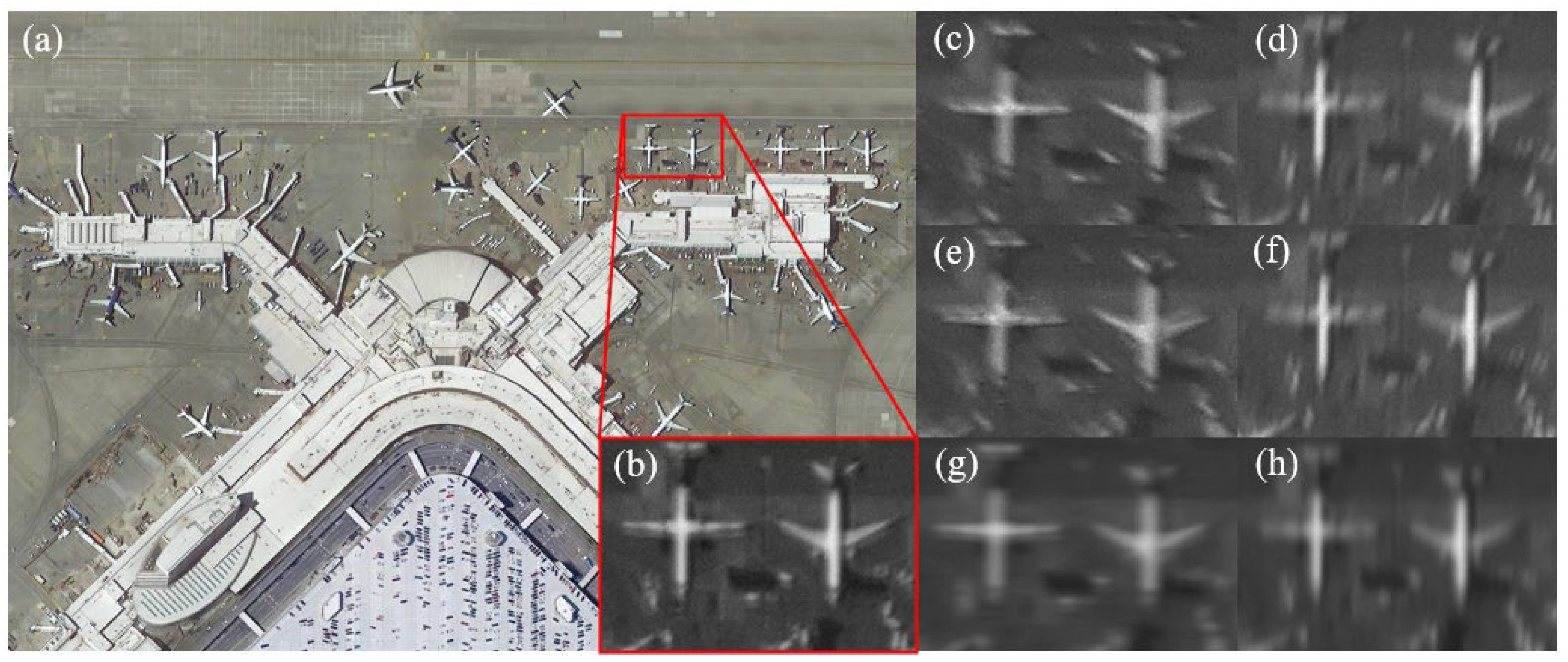
In addition to the quantitative assessment provided by the above all-reference indexes, we also provide some visual results as a qualitative assessment. As can be seen from Figure 11 and Figure 12, it is difficult to accurately simulate the coupling process between the rectangular pupil and other factors in the remote sensing link by using the single PSF for direct convolution. The simulation results are obviously too smooth, which not only loses the noise generated in real images due to the influence of the detector and circuit, but also greatly reduces the sharpness of edges. On the contrary, the proposed method better preserves the texture of typical objects such as aircraft and ships, as well as the obvious dark current noise in the flat area of the image, and achieves more competitive performance. Specifically, it can be seen from Figure 11 that it is difficult for the PSF-conv method to simulate the spatial asymmetric imaging characteristics of the rectangular pupil when the aspect ratio is small (e.g., 3). When the length–width ratio is large (e.g., 10), as shown in Figure 12, although the PSF-conv method can well simulate the huge resolution gap in the direction of the long and short sides of the primary mirror, it generates smoother simulation images, resulting in the loss of much high-frequency information that should exist in the simulation images.

4. Conclusions

In this paper, we firstly analyzed the spatially asymmetric and temporally periodic imaging characteristics of the RSA system’s rectangular rotary pupil. Then, we analyzed the relations between the discrete-domain low-quality image, the discrete-domain high-quality image, and the continuous-domain real-world scene. On this basis, we found that the simulation method which directly convolves the input image with the PSF of the RSA system’s pupil is not suitable for the image simulation of the RSA system. In addition, it is not appropriate to use the existing blur kernel estimation methods to estimate the optimal blur kernel to accurately simulate the effects of the rectangular rotary pupil. To this end, we improved the blur kernel estimation network based on normal convolutions by taking the encoding related to the length–width ratio and the rotation angle of the primary mirror as additional input and using conditionally parameterized convolutions instead of normal convolutions. Unlike normal convolutions, for conditionally parameterized convolutions, the weights of a network are different for each input. Furthermore, by conditioning the model on additional information which is related to the length–width ratio and the rotation angle of the primary mirror, we propose a CCNN. The CCNN can direct the simulation process to generate the simulation images corresponding to different length–width ratios and rotation angles. Finally, we verify the effectiveness of the proposed simulation method through semi-physical imaging experiments. The results show that compared with the real image obtained when the corresponding rectangular entrance pupil optical element is installed, the average values of SSIM and PSNR are 0.8962 and 35.42dB, respectively. Compared with the simulation method using the imaging system’s PSF as the “blur kernel”, the SSIM and PSNR are increased by 0.1447 and 52.61%, respectively. This shows that the proposed simulation method achieves more competitive performance. The proposed simulation method can provide data and theoretical support for the optimization of the RSA system and the corresponding image processing methods.

Author Contributions

Conceptualization, Y.S. and X.Z.; methodology, Y.S.; software, Y.S. and S.J.; validation, Y.S. and J.G.; formal analysis, Y.S. and S.J.; investigation, Y.S. and T.S.; writing—original draft preparation, Y.S. and N.W.; writing—review and editing, Y.S. and S.J.; supervision, X.Z. and J.G. All authors have read and agreed to the published version of the manuscript.

Funding

This work was supported by the National Natural Science Foundation of China (NSFC) (62101160 and 61975043).

Data Availability Statement

Data sharing not applicable.

Conflicts of Interest

The authors declare no conflict of interest.

References

  1. Belward, A.S.; Skøien, J.O. Who launched what, when and why; trends in global land-cover observation capacity from civilian earth observation satellites. ISPRS J. Photogramm. Remote Sens. 2015, 103, 115–128. [Google Scholar] [CrossRef]
  2. Tong, X.; Wang, J.; Lai, G.; Shang, J.; Qiu, C.; Liu, C.; Ding, L.; Li, H.; Zhou, S.; Yang, L. Normalized projection models for geostationary remote sensing satellite: A comprehensive comparative analysis (January 2019). IEEE Trans. Geosci. Remote Sens. 2019, 57, 9643–9658. [Google Scholar] [CrossRef]
  3. Yang, X.; Li, F.; Xin, L.; Lu, X.; Lu, M.; Zhang, N. An improved mapping with super-resolved multispectral images for geostationary satellites. Remote Sens. 2020, 12, 466. [Google Scholar] [CrossRef] [Green Version]
  4. Tzortziou, M.; Mannino, A.; Schaeffer, B.A. Satellite Observations of Coastal Processes from a Geostationary Orbit: Application to estuarine, coastal, and ocean resource management. Am. Geophys. Union 2016, 2016, P54B–1756. [Google Scholar]
  5. Guo, J.; Zhao, J.; Zhu, L.; Gong, D. Status and trends of the large aperture space optical remote sensor. In Proceedings of the 2018 IEEE International Conference on Mechatronics and Automation (ICMA), Changchun, China, 5–8 August 2018; pp. 1861–1866. [Google Scholar]
  6. Zhi, X.; Jiang, S.; Zhang, L.; Wang, D.; Hu, J.; Gong, J. Imaging mechanism and degradation characteristic analysis of novel rotating synthetic aperture system. Opt. Lasers Eng. 2021, 139, 106500. [Google Scholar] [CrossRef]
  7. Jiang, S.; Zhi, X.; Zhang, W.; Wang, D.; Hu, J.; Tian, C. Global Information Transmission Model-Based Multiobjective Image Inversion Restoration Method for Space Diffractive Membrane Imaging Systems. IEEE Trans. Geosci. Remote Sens. 2021, 60, 1–12. [Google Scholar] [CrossRef]
  8. Wang, D.; Zhi, X.; Zhang, W.; Yin, Z.; Jiang, S.; Niu, R. Influence of ambient temperature on the modulation transfer function of an infrared membrane diffraction optical system. Appl. Opt. 2018, 57, 9096–9105. [Google Scholar] [CrossRef] [PubMed]
  9. Zhi, X.; Zhang, S.; Yu, F.; Jiang, S.; Hu, J.; Chen, W. Imaging characteristics and image restoration method for large field circular scanning system. Results Phys. 2021, 31, 104884. [Google Scholar] [CrossRef]
  10. Rai, M.R.; Rosen, J. Optical incoherent synthetic aperture imaging by superposition of phase-shifted optical transfer functions. Opt. Lett. 2021, 46, 1712–1715. [Google Scholar] [CrossRef] [PubMed]
  11. Zhi, X.; Jiang, S.; Zhang, L.; Hu, J.; Yu, L.; Song, X.; Gong, J. Multi-frame image restoration method for novel rotating synthetic aperture imaging system. Results Phys. 2021, 23, 103991. [Google Scholar] [CrossRef]
  12. Tang, J.; Wang, K.; Ren, Z.; Zhang, W.; Wu, X.; Di, J.; Liu, G.; Zhao, J. RestoreNet: A deep learning framework for image restoration in optical synthetic aperture imaging system. Opt. Lasers Eng. 2021, 139, 106463. [Google Scholar] [CrossRef]
  13. Geng, T.; Liu, X.Y.; Wang, X.; Sun, G. Deep shearlet residual learning network for single image super-resolution. IEEE Trans. Image Process. 2021, 30, 4129–4142. [Google Scholar] [CrossRef] [PubMed]
  14. Courtrai, L.; Pham, M.-T.; Lefèvre, S. Small Object Detection in Remote Sensing Images Based on Super-Resolution with Auxiliary Generative Adversarial Networks. Remote Sens. 2020, 12, 3152. [Google Scholar] [CrossRef]
  15. Zhang, K.; Gool, L.V.; Timofte, R. Deep unfolding network for image super-resolution. In Proceedings of the IEEE/CVF Conference on Computer Vision and Pattern Recognition, Seattle, WA, USA, 13–19 June 2020; pp. 3217–3226. [Google Scholar]
  16. Zhang, K.; Zuo, W.; Zhang, L. Learning a single convolutional super-resolution network for multiple degradations. In Proceedings of the IEEE Conference on Computer Vision and Pattern Recognition, Salt Lake City, UT, USA, 18 June–23 June 2018; pp. 3262–3271. [Google Scholar]
  17. Wang, X.; Xie, L.; Dong, C.; Shan, Y. Real-esrgan: Training real-world blind super-resolution with pure synthetic data. In Proceedings of the IEEE/CVF International Conference on Computer Vision, Montreal, Canada, 11–17 October 2021; pp. 1905–1914. [Google Scholar]
  18. Liang, J.; Cao, J.; Sun, G.; Zhang, K.; Van Gool, L.; Timofte, R. Swinir: Image restoration using swin transformer. In Proceedings of the IEEE/CVF International Conference on Computer Vision, Montreal, Canada, 11–17 October 2021; pp. 1833–1844. [Google Scholar]
  19. Xu, Y.; Luo, W.; Hu, A.; Xie, Z.; Xie, X.; Tao, L. TE-SAGAN: An Improved Generative Adversarial Network for Remote Sensing Super-Resolution Images. Remote Sens. 2022, 14, 2425. [Google Scholar] [CrossRef]
  20. Liu, A.; Liu, Y.; Gu, J.; Qiao, Y.; Dong, C. Blind image super-resolution: A survey and beyond. arXiv 2021, arXiv:2107.03055. [Google Scholar] [CrossRef] [PubMed]
  21. Yang, J.; Wright, J.; Huang, T.; Ma, Y. Image super-resolution as sparse representation of raw image patches. In Proceedings of the 2008 IEEE Conference on Computer Vision and Pattern Recognition, Anchorage, AK, USA, 23–28 June 2008; pp. 1–8. [Google Scholar]
  22. Zeyde, R.; Elad, M.; Protter, M. On single image scale-up using sparse-representations. In Proceedings of the International Conference on Curves and Surfaces, Avignon, France, 24–30 June 2010; pp. 711–730. [Google Scholar]
  23. Mallat, S.; Yu, G. Super-resolution with sparse mixing estimators. IEEE Trans. Image Process. 2010, 19, 2889–2900. [Google Scholar] [CrossRef] [PubMed] [Green Version]
  24. Freeman, W.T.; Jones, T.R.; Pasztor, E.C. Example-based super-resolution. IEEE Comput. Graph. Appl. 2002, 22, 56–65. [Google Scholar] [CrossRef] [Green Version]
  25. Michaeli, T.; Irani, M. Nonparametric blind super-resolution. In Proceedings of the IEEE International Conference on Computer Vision, Sydney, Australia, 1–8 December 2013; pp. 945–952. [Google Scholar]
  26. Zontak, M.; Irani, M. Internal statistics of a single natural image. In Proceedings of the CVPR 2011, Colorado Springs, CO, USA, 20–25 June 2011; pp. 977–984. [Google Scholar]
  27. Yang, B.; Bender, G.; Le, Q.V.; Ngiam, J. Condconv: Conditionally parameterized convolutions for efficient inference. In Proceedings of the 33rd International Conference on Neural Information Processing Systems, Vancouver, Canada, 8–14 December 2019; pp. 1307–1318. [Google Scholar]
  28. Mirza, M.; Osindero, S. Conditional generative adversarial nets. arXiv 2014, arXiv:1411.1784. [Google Scholar]
  29. Bell-Kligler, S.; Shocher, A.; Irani, M. Blind super-resolution kernel estimation using an internal-gan. In Proceedings of the 33rd International Conference on Neural Information Processing Systems, Vancouver, Canada, 8–14 December 2019; pp. 284–293. [Google Scholar]
  30. Hu, J.; Shen, L.; Sun, G. Squeeze-and-excitation networks. In Proceedings of the IEEE Conference on Computer Vision and Pattern Recognition, Salt Lake City, UT, USA, 18–23 June 2018; pp. 7132–7141. [Google Scholar]
  31. Wang, Z.; Bovik, A.C.; Sheikh, H.R.; Simoncelli, E.P. Image quality assessment: From error visibility to structural similarity. IEEE Trans. Image Process. 2004, 13, 600–612. [Google Scholar] [CrossRef] [PubMed]
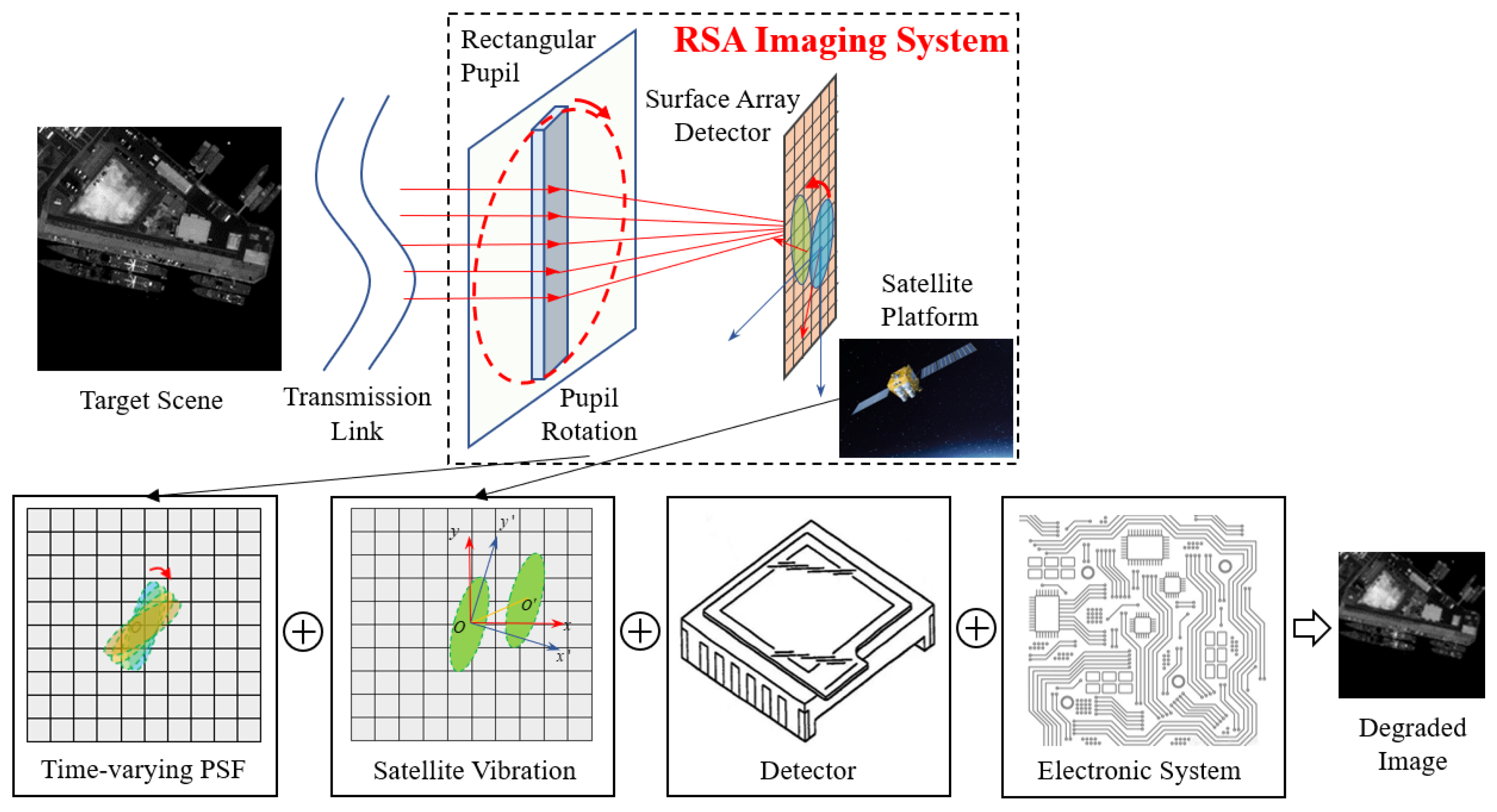
Figure 1. Diagrammatic sketch of the coupling relation of various errors of the rotating synthetic aperture (RSA) imaging system.
Remotesensing 15 00688 g001
Figure 2. Rectangular pupil.
Remotesensing 15 00688 g002
Figure 3. (ad) Point spread function (PSF) with different rotation angles.
Remotesensing 15 00688 g003
Figure 4. Relations between the discrete-domain low-quality image, the discrete-domain high-quality image, and the continuous-domain scene.
Remotesensing 15 00688 g004
Figure 5. The architecture of the proposed conditional convolutional neural network (CCNN).
Remotesensing 15 00688 g005
Figure 6. The architecture of CondConv.
Remotesensing 15 00688 g006
Figure 7. Flowchart of the image simulation method.
Remotesensing 15 00688 g007
Figure 8. Semi-physical imaging experimental facilities. (a) The imaging experiment platform, (b) the primary mirror with a rectangular pupil optical element of length-width ratio 5, and (c) rectangular pupil optical elements.
Remotesensing 15 00688 g008
Figure 9. Target scenes.
Remotesensing 15 00688 g009
Figure 10. Flowchart of validation experiments.
Remotesensing 15 00688 g010
Figure 11. Simulation results when the pupil’s length–width ratio is 3. (a) Original scene, (b) real image taken by the circular primary mirror, (c) real image when the angle of rotation is 0°, (d) real image when the angle of rotation is 90°, (e) simulation image obtained by the CCNN when the angle of rotation is 0°, (f) simulation image obtained by the CCNN when the angle of rotation is 90°, (g) simulation image obtained by the PSF-conv method when the angle of rotation is 0°, and (h) simulation image obtained by the PSF-conv method when the angle of rotation is 90°.
Remotesensing 15 00688 g011
Figure 12. Simulation results when the pupil’s length–width ratio is 10. (a) Original scene, (b) real image taken by the circular primary mirror, (c) real image when the angle of rotation is 0°, (d) real image when the angle of rotation is 90°, (e) simulation image obtained by the CCNN when the angle of rotation is 0°, (f) simulation image obtained by the CCNN when the angle of rotation is 90°, (g) simulation image obtained by the PSF-conv method when the angle of rotation is 0°, (h) simulation image obtained by the PSF-conv method when the angle of rotation is 90°.
Remotesensing 15 00688 g012
Table 1. Experimental results of 12 rotation angles and 4 length–width ratios. The bold value indicates the average value of all test results.
Rotation AnglesMethodLength–Width
Ratio 1
Length–Width
Ratio 3
Length–Width
Ratio 5
Length–Width
Ratio 10
Average
PSNRSSIM
(dB)
PSNRSSIM
(dB)
PSNRSSIM
(dB)
PSNRSSIM
(dB)
PSNRSSIM
(dB)
0PSF-conv22.600.689622.860.716624.370.787624.600.786823.610.7451
Proposed38.100.917736.850.895134.970.902232.720.877135.660.8980
15PSF-conv22.830.736922.530.729624.550.789624.180.775123.520.7578
Proposed37.940.927136.610.897933.730.880232.290.863135.140.8921
30PSF-conv22.060.676522.490.715924.290.787124.130.783423.240.7407
Proposed37.720.921037.060.916234.700.878032.040.860735.380.8939
45PSF-conv22.200.715322.570.741724.210.786224.240.790823.310.7585
Proposed38.110.925736.540.891634.170.891431.800.862135.150.8927
60PSF-conv21.820.715822.220.741224.050.784923.730.783822.950.7564
Proposed38.500.928935.950.895135.190.904031.710.865635.340.8984
75PSF-conv22.220.707422.470.736323.910.784024.020.783823.150.7529
Proposed38.900.922036.910.892034.740.903831.740.874935.570.8982
90PSF-conv22.290.699022.720.731523.770.783224.320.783823.270.7493
Proposed37.850.926736.980.895033.990.904132.060.859935.220.8964
105PSF-conv22.060.717422.480.736323.910.789024.020.788823.120.7579
Proposed37.910.920936.990.891934.290.891932.630.887335.460.8980
120PSF-conv22.360.710322.840.746823.380.781223.630.780523.050.7547
Proposed38.420.911236.940.894735.190.889632.790.886735.840.8955
135PSF-conv22.400.694122.730.707523.460.797923.690.795823.070.7488
Proposed37.620.921237.120.897934.950.879332.170.873135.470.8929
150PSF-conv22.670.709022.120.715823.830.791723.740.781323.090.7495
Proposed38.880.916536.020.894934.380.902531.940.885435.310.8998
165PSF-conv22.230.685322.610.714723.880.792523.910.789623.160.7455
Proposed38.490.917136.430.895034.680.902332.330.881235.480.8989
AveragePSF-conv22.310.704722.550.727823.970.787924.020.785323.210.7515
Proposed38.200.921336.700.896434.580.894132.190.873135.420.8962
Disclaimer/Publisher’s Note: The statements, opinions and data contained in all publications are solely those of the individual author(s) and contributor(s) and not of MDPI and/or the editor(s). MDPI and/or the editor(s) disclaim responsibility for any injury to people or property resulting from any ideas, methods, instructions or products referred to in the content.