Communication

Rectangular Microstrip Array Feed Antenna for C-Band Satellite Communications: Preliminary Results

by
Catur Apriono
1,*,
B. Pratiknyo Adi Mahatmanto
1 and
Filbert H. Juwono
2
1
Department of Electrical Engineering, Faculty of Engineering, Universitas Indonesia, West Java 16424, Indonesia
2
Computer Science Program, University of Southampton Malaysia, Iskandar Puteri 79100, Johor, Malaysia
*
Author to whom correspondence should be addressed.
Remote Sens. 2023, 15(4), 1126; https://doi.org/10.3390/rs15041126
Submission received: 30 November 2022 / Revised: 4 February 2023 / Accepted: 6 February 2023 / Published: 18 February 2023
(This article belongs to the Section Remote Sensing Communications)

Abstract

:
This paper proposes a rectangular array configuration of microstrip antennas combined with a parabolic reflector for C-band satellite communications. The antenna operates in the frequency range of 3.8–4.2 GHz. In particular, the proposed antenna is a 2 × 2 feed antenna on a parabolic system. It uses a multilayer microstrip array antenna with proximity coupling and coaxial probe techniques as a feeding technique. The fabricated antenna operates at 3.8–4.4 GHz and 12.1 dBi gain at frequency 4.148 GHz. Through simulation, combining the antenna with a 2.4 m parabolic reflector results in a gain of 33.1 dBi. In conclusion, the proposed antenna configuration achieves the expected high gain and narrow beamwidth for the E plane and the H plane.

1. Introduction

Satellite systems offer a wide coverage area for communication and other purposes, such as remote sensing applications. However, creating a satellite communication system is a challenging task. The design considers many parameters to meet acceptable requirements. One of the difficult circumstances is the high rainfall rate. Compared to other satellite communication channels, satellites using C-band frequencies, such as Himawari satellites, are more reliable in severe weather conditions such as heavy rain [1,2].
An antenna is a crucial component of a satellite communication system. In particular, high-gain antennas are required to provide a good communication link between the satellite and ground stations. These days, earth stations frequently employ horn antennas and satellite dishes (parabolic reflectors). To meet the design requirements (i.e., high gain, directed radiation patterns, and polarization), a parabolic reflector can be used [1]. The reflector is necessary to obtain the expected gain of a receiving ground station antenna higher than 30 dBi. This value indicates that the radiation pattern is directional with a small beamwidth or close to a pencil beam pattern. Meanwhile, for the feeding antenna, the required gain is greater than 10 dB with a symmetric beamwidth of the E plane and the H plane to conform to a reflector.
The microstrip antenna is one of several antennas that can be used as a satellite data receiver, particularly in the C-band frequency range [3,4,5]. Some types of microstrip antennas for satellite communications include microstrip antenna with slot [6], microstrip antenna with electromagnetic bandgap technique [7], microstrip antenna with inset feed technique [8,9,10], and microstrip antenna with E-shaped technique [11]. However, a reflector has commonly been integrated with a microstrip antenna to achieve the desired performance. In particular, it has been used in dual-band circular patch array [12], microstrip printed dipole [13], two-element microstrip array with Wilkinson power divider [14], 2 × 2 microstrip array antenna [15], waveguide combined with 2 × 2 microstrip array antenna [16], and dual-circularly polarized microstrip array antenna [17,18].
Some critical issues may occur when trying to increase the gain of microstrip antennas using array techniques. The issues include the need for many elements of the array to achieve the high expected gain, which increases antenna size, losses, and complexities in the feeding system. The antenna also becomes mechanically fragile due to its large area. Therefore, another feasible solution is needed to obtain good performance from microstrip antennas for communication satellites.
This paper proposes the design and fabrication of a rectangular patch array microstrip antenna for a geostationary ground station of the Himawari satellite communication system operating at frequencies of 3.8–4.2 GHz with more than 30 dBi gain and linear polarization. The proposed design is a combination of a multilayer microstrip array antenna, proximity-coupled feed, a coaxial probe feeding technique, and a parabolic reflector. Each technique of this combination contributes to improved antenna performance. The antenna array technique is selected as it can significantly increase the gain value proportional to the number of single antennas in the array [19,20,21]. The feed method considered is a proximity-coupled feed or an electromagnetically coupled feed [22,23,24]. This feeding method is suitable for planar feeding, as it provides less radiation than conventional microstrip feed (closer to the ground plane) and provides a wider bandwidth (no influence of inductance on the probe so the substrate can be thicker) [25,26]. Another consideration is the coaxial probe feeding technique. It offers easy adjustment to the coaxial cable connected to the connector, and easy to obtain the matching conditions by adjusting the feed position [27,28]. Those three parts construct the feeding antenna. Meanwhile, the parabolic reflector for collimating the radiation from the feeder antenna increases the gain performance.
The fabricated 2 × 2 microstrip array antenna has a 3.8–4.4 GHz bandwidth and a gain of 12.1 dBi at a frequency of 4.148 GHz. Moreover, we believe that combining the microstrip array antenna with a parabolic reflector results in an improved gain and maintains the reasonable dimension of the antenna system. In this work, using simulation, we assess the effect of the reflector on the designed microstrip antenna and discover a gain improvement of about 21 dB. Therefore, our designed antenna system meets the gain requirement for satellite communications. Furthermore, the proposed antenna system is competitive because of its low cost, low profile, and compactness due to the combination of a low-cost feeding antenna and the widely used parabolic reflector.
The rest of this paper is organized as follows. The design of the microstrip antenna, including the fabricated antenna and the results of simulation and measurement, is covered in Section 2. The simulation results of the combination of the proposed microstrip antenna and the parabolic reflector are shown in Section 3. Finally, Section 4 concludes this paper.

2. Antenna Design

Figure 1 shows the structure of the proposed microstrip array antenna design. The top layer consists of 2 × 2 array antennas considering the antenna area at an optimum size, which is as small as possible, as a feeding antenna to avoid blocking effect or power reflection, as some radiation reflects back from the surface of the parabolic reflector and touches the antenna area. The optimum number of radiating elements is four with a two-dimensional configuration to achieve the desired gain and symmetric beamwidth. The middle and bottom layers show the proximity-coupled feed and the coaxial probe, respectively. This combination obtains a wider bandwidth and easy matching conditions. The transmission line from the probe point to each array element on the middle layer has a similar path length to keep the linear polarization. The quarter-wavelength impedance matching technique is also applied to maintain the matching condition and avoid reflection loss.
The parameter values for the top and bottom layers are given as follows: patch width, W p = 40.93 mm, patch length L p = 20.76 mm, substrate width, W s 2 = 120 mm, and substrate length, L s 2 = 85 mm. The widths of the microstrip line for the middle layer are W f = 6.69 mm, W o = 0.32 mm, W A = 1.71 mm, W B = 0.26 mm, W C = 0.75 mm and W D = 0.78 mm. The lengths of the microstrip line for the middle layers are L f = 15.71 mm, L o = 27.15 mm, L A = 3.78 mm, L B = 38.59 mm, L C = 8.37 mm, L D = 7.46 mm. These approximation values are simulated and characterized to reach the most optimum parameters.
The designed antenna is fabricated using the RT/Duroid-5880 substrate material with a dielectric constant value ( ϵ r ) of 2.2, a thickness of 1.575 mm, a tangential loss ( tan δ ) of 0.0009, and a copper thickness of 0.035 mm. Figure 2 shows the fabricated microstrip array antenna from the upper, middle, and lower layers. Measurement was carried out using the Rohde & Schwarz ZVL Network Analyzer 9–13.6 GHz for the measurement of S parameters, the Hewlett Packard 8753E 32–6 GHz Network Analyzer, and the Schwarzbeck BBHA 9120A as a reference antenna when measuring radiation pattern and gain.
The simulated and measured reflection coefficient for the designed antenna is shown in Figure 3. It can be seen that the designed antenna results in a good reflection coefficient ( S 11 ) of −14.243 dB at a frequency of 4.148 GHz. It also has a bandwidth of 703.7 MHz in a frequency range of 3.8–4.4 GHz. The gain of the antenna is 12.75 dBi. Furthermore, the measured reflection coefficient is in good agreement with the simulated one.
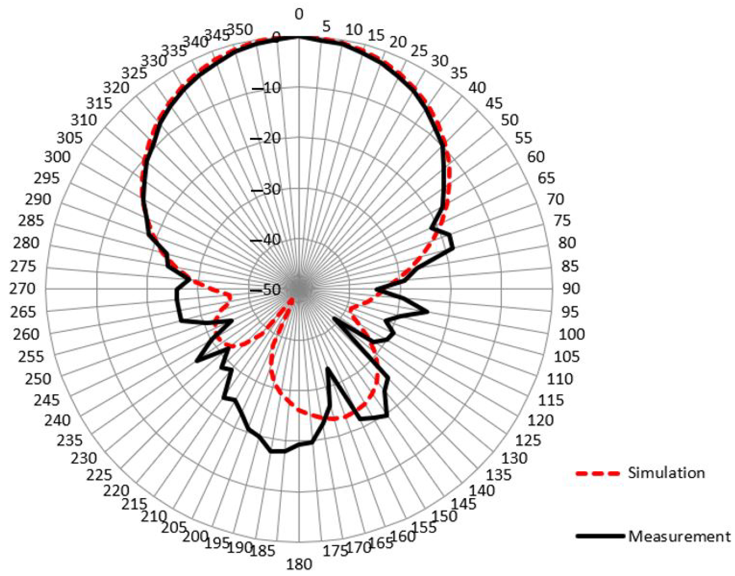
Figure 4 and Figure 5 show the radiation pattern for the simulation and measurement of the antenna in the E plane and the H plane, respectively. It can be seen that the measurement results verify the simulation results. Both show a directional radiation pattern in which the angle of 0 has the highest level compared to the other angles. Then the results of the radiation pattern measurement in the E plane show better characteristics in the sidelobe, where the received power level of the 40 –140 angle and the 220 –320 angle has a much lower value than the simulation results.
Figure 6 shows the gain comparison between the simulation and the measurement in a frequency range of 3.0–5.0 GHz. The measurement shows that the gain value varies from 6.16 dBi at the 5 GHz frequency to a maximum of 12.074 dBi, which occurs at the 4.148 GHz frequency. There is a difference in the gain of 0.626 dB at the 4.148 GHz frequency, where the simulation result gain is higher than the measured gain. The difference in gain between simulation and manufacturing is still acceptable. The lower result could be due to defects in the fabrication process and measurement, such as poor soldering and measurement setup.

3. Antenna with Reflector: Simulation Results

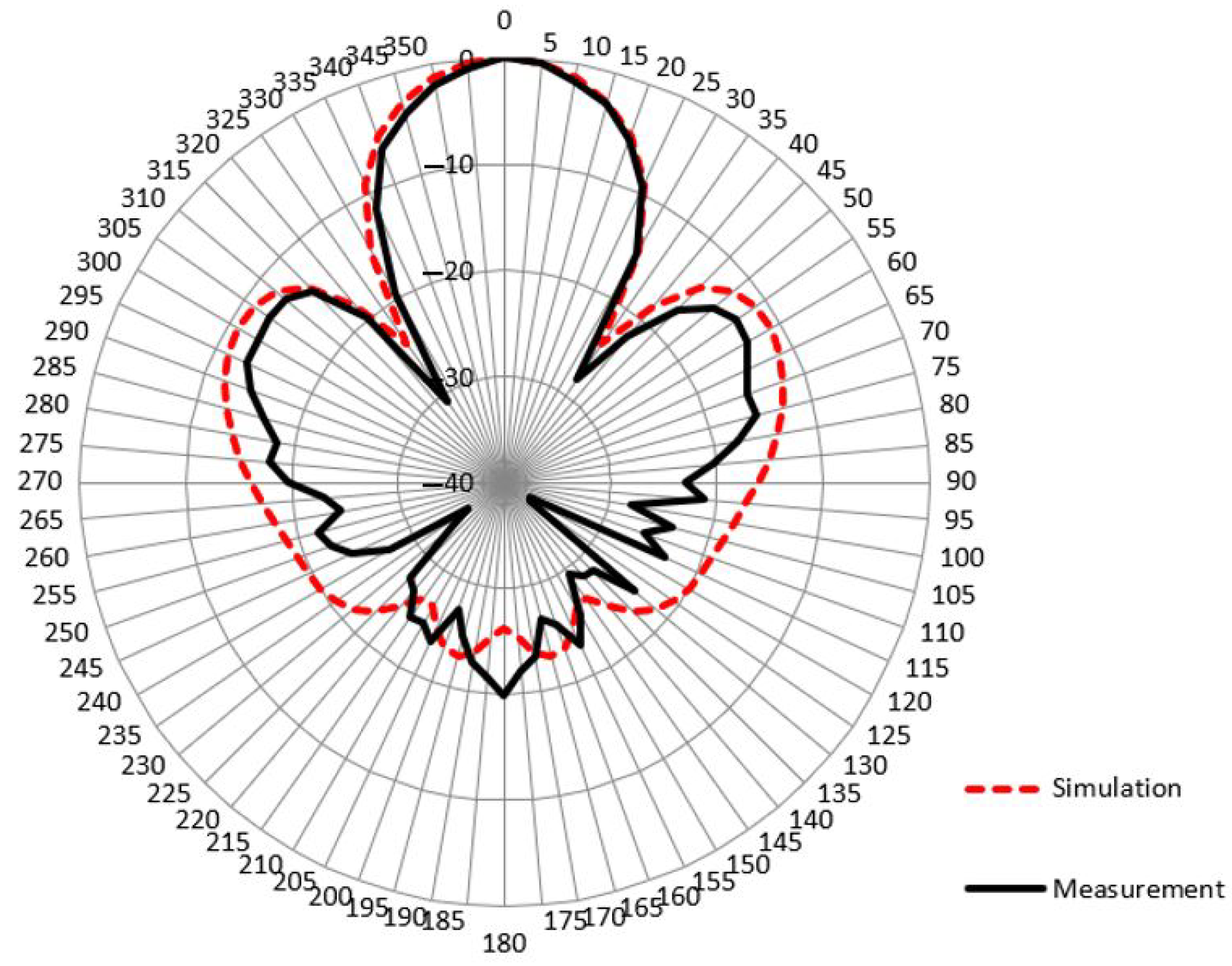
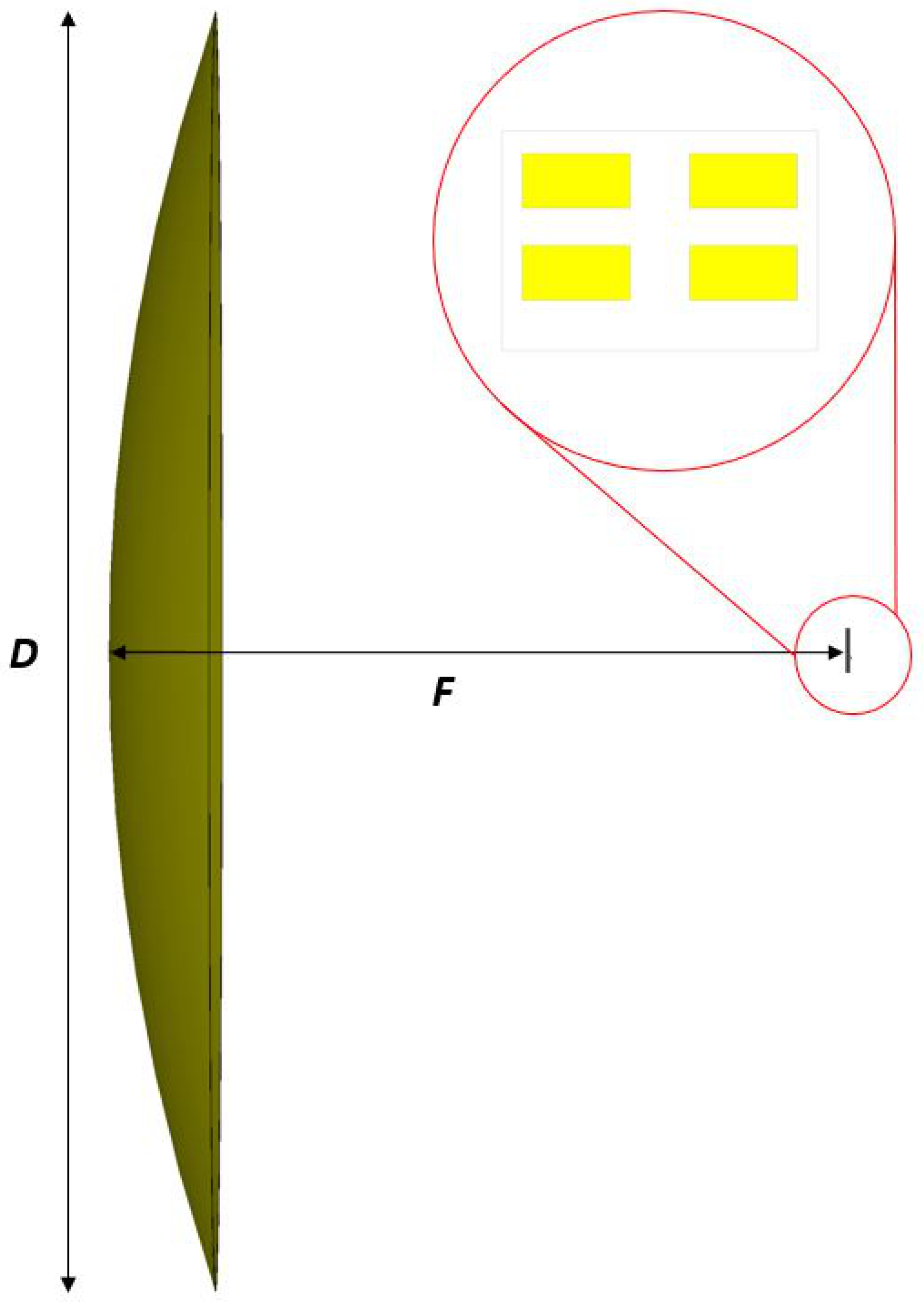
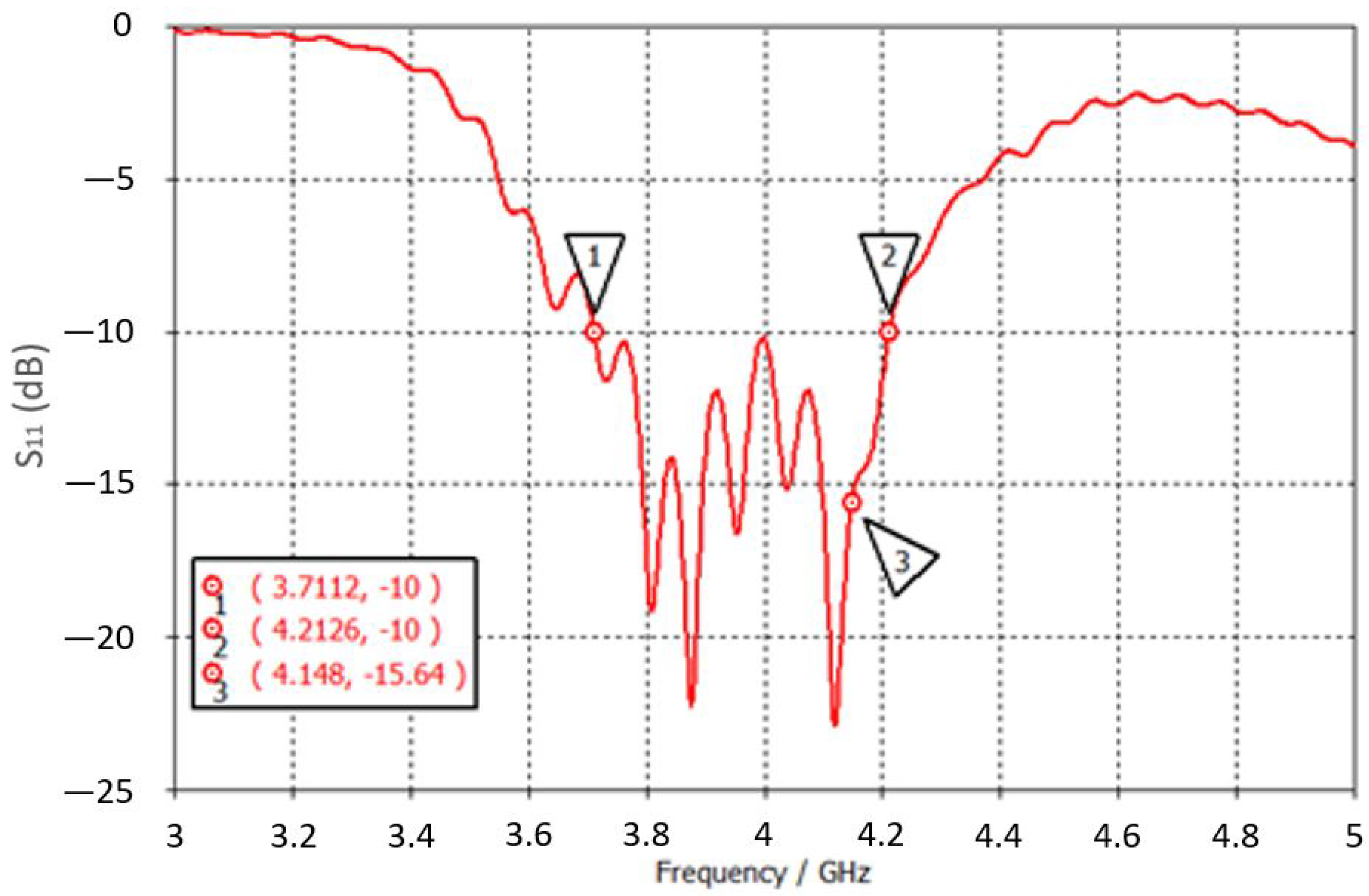
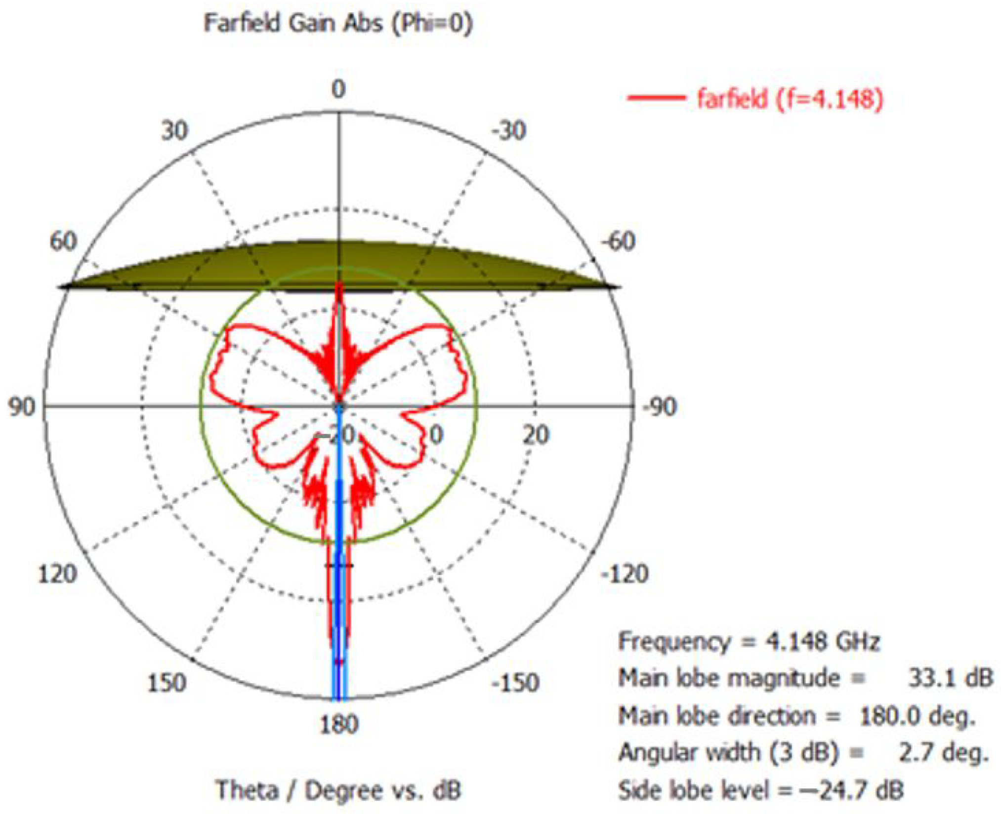
We simulate the 2 × 2 microstrip array antenna with a D = 2.4 m diameter parabolic reflector. Figure 7 shows the simulation configuration consisting of a feeder antenna on the right side and a parabolic reflector on the left side. The radiation emitted from the array antenna is directed to the parabolic reflector so that the beam is reflected and focused on the destination antenna. The diameter is widely used and available to obtain a low-cost system. Directivity can be improved by optimizing the focal point distance of the parabolic antenna (F). Optimization is carried out by parameterizing the distance from the feeding antenna to the reflector on the main axis. The optimal focal point distance parameter is F = 1188.3 mm. It has a good reflection coefficient at a frequency of 4.148 GHz with a value of −15.64 dB. The antenna has a bandwidth of 501.4 MHz in the frequency range of 3.7112–4.2126 GHz, as shown in Figure 8. The directional radiation pattern at a frequency of 4.148 GHz can be seen in the polar E plane and the H plane, as shown in Figure 9 and Figure 10, respectively. The antenna system has a gain of 33.1 dBi.
In particular, the increased gain is followed by a narrowing of the beamwidth, resulting in a distinctive directed beam pattern. In the E-plane, the sidelobe level decreases significantly. Moreover, the E- and H-plane conditions are balanced, as evidenced by the almost identical beamwidth and sidelobe level values. In addition, the performance comparison of the proposed antenna with other designs for C-band is summarized in Table 1. It is obvious that the addition of a reflector to the antenna improves performance in terms of gain.

4. Conclusions and Future Work

The fabricated 2 × 2 microstrip array antenna has a gain of 12.1 dBi at a frequency of 4.148 GHz. The measured 10-dB bandwidth is 3.8–4.4 GHz. When the 2 × 2 microstrip array antenna combines with a 2.4-m parabolic reflector, a gain of 33.1 dBi is achieved, meeting the required antenna specifications for receiving C-band satellite data transmission. Measuring the antenna with a reflector is a challenging task due to the complexity of combining two antennas and the measurement setup that should comply with the far-field requirement of at least 160 m. This will be conducted as part of our future work.

Author Contributions

Conceptualization, C.A. and B.P.A.M.; methodology, C.A.; software, B.P.A.M.; validation, C.A. and F.H.J.; formal analysis, B.P.A.M. and F.H.J.; writing—original draft preparation, C.A. and B.P.A.M.; writing—review and editing, F.H.J.; visualization, B.P.A.M.; supervision, C.A. and F.H.J.; project administration, C.A.; funding acquisition, C.A. All authors have read and agreed to the published version of the manuscript.

Funding

This work was supported by the Ministry of Education, Culture, Research, and Technology, the Republic of Indonesia through Penelitian Dasar Unggulan Perguruan Tinggi (PDUPT) Grant, contract number: NKB-847/UN2.RST/HKP.05.00/2022, the year 2022.

Data Availability Statement

No new data were created or analyzed in this study. Data sharing is not applicable to this article.

Conflicts of Interest

The authors declare no conflict of interest.

References

  1. Ritronnasak, R.; Charoenpru, T.; Waranon, L. Integration and Installation of The Low Cost C-band Receiving System for Himawari-8 Satellite. In Proceedings of the 2018 15th International Conference on Electrical Engineering/Electronics, Computer, Telecommunications and Information Technology (ECTI-CON), Chiang Rai, Thailand, 18–21 July 2018; pp. 732–735. [Google Scholar]
  2. Sun, H.; Zhang, F.; Jia, C. Research on Key Technologies of C/Ku Dual-Band Satellite Communication. In Proceedings of the 2019 International Conference on Robots & Intelligent System (ICRIS), Haikou, China, 15–16 June 2019; pp. 149–151. [Google Scholar]
  3. Hashmi, R.M.; Esselle, K.P. Planar high-gain antennas for direct broadcast satellite reception. In Proceedings of the 2016 IEEE 2nd Australian Microwave Symposium (AMS), Adelaide, SA, Australia, 11–12 February 2016; pp. 17–18. [Google Scholar]
  4. Kumar, C.; Reddy, B.S.; Kumar, B.P.; Kumar, V.S.; Srinivasan, V.V. Novel high gain dual band single aperture array with large cross-polarized isolation at Ku-band for the TT&C system of a geostationary satellite. In Proceedings of the 2017 IEEE International Conference on Antenna Innovations & Modern Technologies for Ground, Aircraft and Satellite Applications (iAIM), Bangalore, India, 24–26 November 2017; pp. 1–5. [Google Scholar]
  5. Kumar, C.; Puram, V.S.; Kumar, V.S.; Venkataramana, D. Design Consideration of High Gain Microstrip Antenna Arrays for Telemetry Tracking and Command System of Geostationary Satellites. In Proceedings of the 2018 IEEE Indian Conference on Antennas and Propogation (InCAP), Hyderabad, India, 16–19 December 2018; pp. 1–3. [Google Scholar]
  6. Thaker, N.M.; Ramamoorthy, V. A Review on Circular Microstrip Patch Antenna with Slots for C Band Applications. Int. J. Sci. Eng. Res. 2014, 5, 1039–1043. [Google Scholar]
  7. Abdulhameed, M.K.; Isa, M.; Zakaria, Z.; Mohsin, M.K.; Attiah, M.L. Mushroom-Like EBG to Improve Patch Antenna Performance for C-Band Satellite Application. Int. J. Electr. Comput. Eng. 2018, 8, 3875–3881. [Google Scholar] [CrossRef]
  8. Dahri, F.A.; Soomro, R.A.; Memon, S.A.; Memon, Z.; Memon, M.H. An Optimized Inset Feed Circular Cross Strip Antenna Design for C-Band Satellite Links. Int. J. Adv. Comput. Sci. Appl. 2018, 9, 238–242. [Google Scholar] [CrossRef] [Green Version]
  9. Sran, S.S.; Sivia, J.S. Quad Staircase Shaped Microstrip Patch Antenna for S, C and X Band Applications. Procedia Comput. Sci. 2016, 85, 443–450. [Google Scholar] [CrossRef] [Green Version]
  10. Singh, S.; Sahayam, N. New 2GHz Broadband Microstrip Patch Antenna for C-band Pervasive Wireless Communication. Int. J. Eng. Sci. Adv. Technol. 2012, 2, 971–974. [Google Scholar]
  11. e Munir, M.; Mahmood, K.; Khan, M. E-Shape Patch Antenna For Mobile Phone, S-Band and C-Band Applications. J. Mech. Contin. Math. Sci. 2018, 13, 115–127. [Google Scholar] [CrossRef]
  12. Debbarma, K.; Bhattacharjee, R. Microstrip patch antenna feed for offset reflector antenna for dual band application. Int. J. Microw. Comput. Aided Eng. 2019, 29, e21999. [Google Scholar] [CrossRef]
  13. Qudrat-E-Maula, M.; Shafai, L. Low-Cost, Microstrip-Fed Printed Dipole for Prime Focus Reflector Feed. IEEE Trans. Antennas Propag. 2012, 60, 5428–5433. [Google Scholar] [CrossRef]
  14. Mohamed, N.; Mohamad, S.Y.; Farihah Abdul Malek, N.; Mohd Isa, F.N. A Compact and Lightweight Microstrip Antenna Array with Wilkinson Power Divider for X-band Application at 9.5 GHz. In Proceedings of the 2019 IEEE Asia-Pacific Conference on Applied Electromagnetics (APACE), Malacca, Malaysia, 25–27 November 2019; pp. 1–5. [Google Scholar]
  15. Bhattacharjee, R.; Debbarma, K. Analysis of offset reflector performance fed by 2×2 microstrip antenna array using GO technique. In Proceedings of the 2018 3rd International Conference on Microwave and Photonics (ICMAP), Dhanbad, India, 9–11 February 2018; pp. 1–2. [Google Scholar]
  16. Jha, K.R.; Sharma, S.K. Waveguide integrated microstrip patch array feed source for a reflector antenna at THz frequency. In Proceedings of the 2014 IEEE Antennas and Propagation Society International Symposium (APSURSI), Memphis, TN, USA, 6–11 July 2014; pp. 1465–1466. [Google Scholar]
  17. Nagasaka, M.; Nakazawa, S.; Tanaka, S. Prototype of a dual-circularly polarized parabolic reflector antenna with microstrip antenna array for 12-GHz band satellite broadcasting reception. In Proceedings of the 2016 10th European Conference on Antennas and Propagation (EuCAP), Davos, Switzerland, 10–15 April 2016; pp. 1–5. [Google Scholar]
  18. Nagasaka, M.; Nakazawa, S.; Tanaka, S. Dual-circularly polarized parabolic reflector antenna with microstrip antenna array for 12-GHz band satellite broadcasting reception. In Proceedings of the 2016 International Symposium on Antennas and Propagation (ISAP), Okinawa, Japan, 24–28 October 2016; pp. 692–693. [Google Scholar]
  19. Hasan, M.; Seo, M. High-gain 2 × 2 UWB antenna array with integrated phase inverter. Electron. Lett. 2018, 54, 612–614. [Google Scholar] [CrossRef]
  20. Mei, L.; Zhang, N.; Liu, L.; Wang, D.; Ma, Y.; Li, Y.; Jiao, X.; Guo, Y. A C-band 16×16 array antenna for microwave communication. In Proceedings of the 2016 11th International Symposium on Antennas, Propagation and EM Theory (ISAPE), Guilin, China, 18–21 October 2016; pp. 299–302. [Google Scholar]
  21. Reynalda, T.; Munir, A.; Bharata, E. Characterization of 4×4 high gain microstrip array antenna for 3.3 GHz WiMAX application. In Proceedings of the 2011 6th International Conference on Telecommunication Systems, Services, and Applications (TSSA), Denpasar, Indonesia, 20–21 October 2011; pp. 215–218. [Google Scholar]
  22. Mariyanto, A.S.S.; Irfan, M.; Ariessaputra, S.; Mustiko, O.M.C. Design and realization of microstrip antenna for GPS application using proximity coupled techniques. In Proceedings of the 2017 11th International Conference on Telecommunication Systems Services and Applications (TSSA), Lombok, Indonesia, 26–27 October 2017; pp. 1–4. [Google Scholar]
  23. Widiandari, R.; Munir, A. Proximity coupled x-band patch antenna array with dual polarization. In Proceedings of the 2016 International Electronics Symposium (IES), Denpasar, Indonesia, 29–30 September 2016; pp. 165–168. [Google Scholar]
  24. Bakariya, P.S.; Dwari, S.; Sarkar, M.; Mandal, M.K. Proximity-Coupled Multiband Microstrip Antenna for Wireless Applications. IEEE Antennas Wirel. Propag. Lett. 2015, 14, 646–649. [Google Scholar] [CrossRef]
  25. Bakariya, P.S.; Dwari, S.; Sarkar, M.; Mandal, M.K. Proximity-Coupled Microstrip Antenna for Bluetooth, WiMAX, and WLAN Applications. IEEE Antennas Wirel. Propag. Lett. 2015, 14, 755–758. [Google Scholar] [CrossRef]
  26. García-Marín, E.; Masa-Campos, J.; Sánchez-Olivares, P. 4 × 4 stacked patch array with siw and microstrip corporate feeding network for ku-band. In Proceedings of the 2016 10th European Conference on Antennas and Propagation (EuCAP), Davos, Switzerland, 10–15 April 2016; pp. 1–4. [Google Scholar]
  27. Zhang, Y.; Zheng, H.; Gao, B.; Tang, C.; Liu, R.; Wang, M. A Compact Dual-band Antenna for 5G Application. In Proceedings of the 2019 Cross Strait Quad-Regional Radio Science and Wireless Technology Conference (CSQRWC), Taiyuan, China, 18–21 July 2019; pp. 1–2. [Google Scholar]
  28. Han, Y.n.; Zheng, Z.x.; Sun, A.m. Optimizing antennas distribution on complicated structures by conformal finite-difference time domain. In Proceedings of the 2012 6th Asia-Pacific Conference on Environmental Electromagnetics (CEEM), Shanghai, China, 6–9 November 2012; pp. 54–57. [Google Scholar]
  29. Islam, M.T.; Anika, N.U.; Mahmud, M.; Islam, M.; Abir, M.H.; Chy, M.H. Design of a Microstrip Patch Antenna for both C-band and X-band Applications. In Proceedings of the 2020 2nd International Conference on Advanced Information and Communication Technology (ICAICT), Dhaka, Bangladesh, 28–29 November 2020; pp. 7–10. [Google Scholar]
  30. Juarez-Ortiz, V.A.; Perea-Tamayo, R. Design of a C-band High Gain Microstrip Antenna Array for CubeSat Standard. In Proceedings of the 2018 IEEE MTT-S Latin America Microwave Conference (LAMC 2018), Arequipa, Peru, 12–14 December 2018; pp. 1–3. [Google Scholar]
  31. Zaman, M.R.; Islam, M.T.; Misran, N.; Mandeep, J.S. Analysis of Resonance Response Performance of C-Band Antenna Using Parasitic Element. Sci. World J. 2014, 2014, 131374. [Google Scholar] [CrossRef] [Green Version]
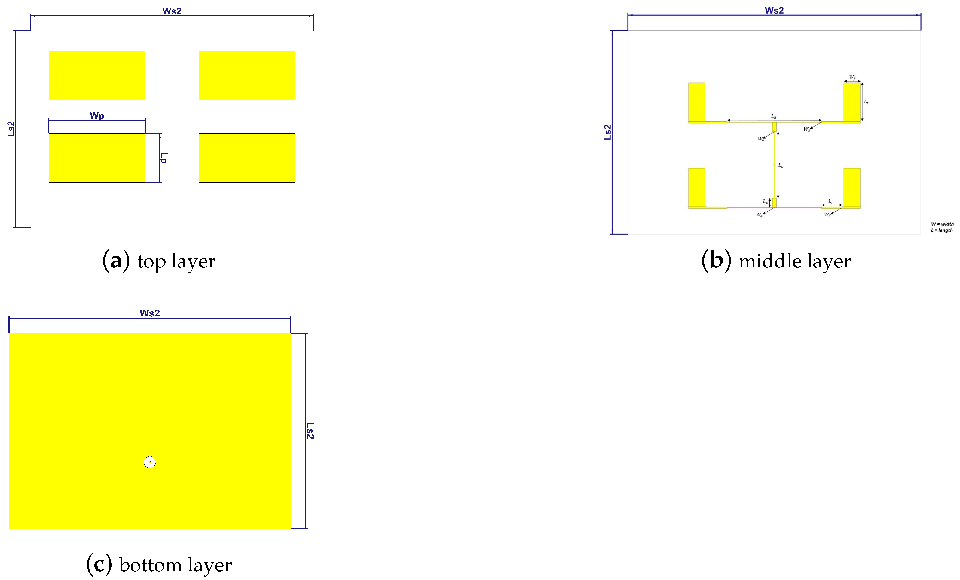
Figure 1. The 2 × 2 microstrip array antenna design.
Remotesensing 15 01126 g001
Figure 2. The fabricated 2 × 2 microstrip array antenna design.
Remotesensing 15 01126 g002
Figure 3. Simulated and measured reflection coefficient.
Remotesensing 15 01126 g003
Figure 4. E-plane radiation pattern at 4.148 GHz.
Remotesensing 15 01126 g004
Figure 5. H-plane radiation pattern at 4.148 GHz.
Remotesensing 15 01126 g005
Figure 6. Gain comparison of the microstrip array antenna.
Remotesensing 15 01126 g006
Figure 7. A simulation configuration schematic.
Remotesensing 15 01126 g007
Figure 8. Reflection coefficient of the array antenna combined with a 2.4-m parabolic reflector.
Remotesensing 15 01126 g008
Figure 9. E-plane radiation pattern of array antenna combined with a 2.4-m parabolic reflector.
Remotesensing 15 01126 g009
Figure 10. H-plane radiation pattern of array antenna combined with a 2.4-m parabolic reflector.
Remotesensing 15 01126 g010
Table 1. Comparison of microstrip antennas in C-band.
ReferenceSubstrateDimension (mm)FrequencyGain
[29]Rogers RT 588017.79 × 21.96 × 1.68.864 GHz5.09 dB
[30]RT/Duroid 600274 × 74 × 1.5245.86 GHz13.34 dB
[31]FR480 × 80 × 1.65.7 GHz6.16 dBi
7.6 GHz2.5 dBi
ProposedRT/Duroid 5880120 × 85 × 3.2554.148 GHz12.1 dBi (w/o refl.)
33.1 dBi (w/ refl.)
Disclaimer/Publisher’s Note: The statements, opinions and data contained in all publications are solely those of the individual author(s) and contributor(s) and not of MDPI and/or the editor(s). MDPI and/or the editor(s) disclaim responsibility for any injury to people or property resulting from any ideas, methods, instructions or products referred to in the content.