Abstract
The application of deep learning in remote sensing image classification has been paid more and more attention by industry and academia. However, manually designed remote sensing image classification models based on convolutional neural networks usually require sophisticated expert knowledge. Moreover, it is notoriously difficult to design a model with both high classification accuracy and few parameters. Recently, neural architecture search (NAS) has emerged as an effective method that can greatly reduce the heavy burden of manually designing models. However, it remains a challenge to search for a classification model with high classification accuracy and few parameters in the huge search space. To tackle this challenge, we propose TPENAS, a two-phase evolutionary neural architecture search framework, which optimizes the model using computational intelligence techniques in two search phases. In the first search phase, TPENAS searches for the optimal depth of the model. In the second search phase, TPENAS searches for the structure of the model from the perspective of the whole model. Experiments on three open benchmark datasets demonstrate that our proposed TPENAS outperforms the state-of-the-art baselines in both classification accuracy and reducing parameters.
1. Introduction
With the advancement of remote sensing technology, more and more abundant ground information can be obtained from remote sensing images, which facilitates many research directions and applications, such as change detection [1,2,3,4,5,6], land use classification [7,8], remote sensing image classification [9,10], etc. As a basic task of remote sensing image processing [11], remote sensing image classification is the classification of remote sensing scene images into a group of semantic categories, which has been widely used in environmental monitoring [12], geospatial object detection [13], and urban planning [14].
In recent decades, with the advancement of deep learning [15,16,17,18], many algorithms [9,10,19] have been proposed to solve the remote sensing image classification problem. These algorithms can roughly be categorized into traditional and deep learning-based algorithms, which mainly differ in the way of feature extraction. The former extracts the features of remote sensing images by manually designing feature extraction operators, such as improved fisher kernel (IFK) [20], spatial pyramid matching (SPM) [21], and bag-of-visual-words (BoVW) [22] algorithms. The latter automatically extracts remote sensing image features through deep learning methods such as the autoencoder (AE) [23,24,25], CNN [26], and generative adversarial network (GAN) [27,28,29]. The traditional methods need to specially design a feature extraction operator for the remote sensing image. The extracted features are low-level features, such as texture, color, shape, and gradient, resulting in low classification accuracy on remote sensing image classification tasks. In contrast, deep learning-based methods can automatically learn high-level semantic features of remote sensing images without the need for special feature extractors and achieve high overall accuracy on the remote sensing image classification task. Otávio et al. [30] compared the overall accuracy of deep learning methods with traditional methods on the UC Merced Land-use (UCM21) dataset [22] and demonstrated that deep learning methods outperform traditional methods.
In the past ten years, convolutional neural networks (CNNs) have made a significant breakthrough in image classification. A large number of excellent CNN models have emerged, such as AlexNet [31], VGGNet [32], ResNet [33], GoogleNet [34], and DensNet [35]. However, when applied to remote sensing image classification, these classical CNN models do not perform as well due to the unique characteristics of remote sensing images, such as big intra-class diversity, high inter-class similarity, and coexistence of multiple ground objects. Therefore, many deep learning models [36,37,38,39] are tailored for remote sensing image classification. Yu et al. [37] proposed the HABFNet framework to alleviate the problems of high intra-class diversity and high inter-class similarity in remote sensing images. HABFNet uses ResNet50 to extract image features, then enhances features at different levels through a channel attention scheme, and fuses features through bilinear pooling. The fused features have a stronger discriminative ability, which improves the classification accuracy of the algorithm in remote sensing image classification. Wei et al. [38] proposed a novel CAD network that uses an attention mechanism to extract more discriminative features, which alleviates the difficulty of classification caused by large changes in object scale. Gong et al. [39] proposed D-CNN to alleviate the problems of high intra-class diversity and high inter-class similarity in remote sensing images, thereby further improving remote sensing image classification accuracy. Wang et al. [40] proposed a semi-supervised classification framework by designing the inner-class dense neighbors (IDN) algorithm to reduce the reliance on the labels of the samples and simultaneously improve the classification accuracy of the model. CNN-based algorithms perform very well on remote sensing image classification tasks.
Although deep learning methods have achieved high classification accuracy in remote sensing image classification, it is extremely difficult for those without professional knowledge about deep learning to design a model with high classification accuracy. In recent years, NAS has emerged as a promising alternative method, which can automatically design a CNN model with high classification accuracy without prior knowledge. The existing NAS methods can be divided into three categories: NAS based on reinforcement learning (NAS-RL) [41,42,43], evolutionary neural architecture search (ENAS) [44,45,46], and NAS based on gradient (NAS-G) [47,48,49]. The evolutionary algorithm (EA) [50,51] is a heuristic global optimization algorithm. Due to its powerful optimization ability and easy parallel computation, the evolutionary algorithm has attracted more and more scholars’ attention in the automatic design of deep neural network structure. Real et al. [44] first proposed using evolutionary computation to optimize the structure of a CNN. This method does not require any human operations after the algorithm is executed and finally outputs a fully trained CNN model. The algorithm achieves competitive classification accuracy on the CIFAR-10 and CIFAR-100 datasets, but at a prohibitively high computational cost. Since then, many researchers have proposed many schemes to reduce computational costs. Elsken et al. [52] proposed a simple and efficient NASH algorithm, which uses network morphisms [53] to generate weight-inherited sub-networks and efficiently optimizes an excellent CNN architecture through a simple hill-climbing algorithm. Hui et al. [54] proposed the EENA algorithm, which uses prior knowledge to guide the evolutionary process, thereby accelerating the search process. Wang et al. [55] evaluated individuals with some batch data randomly selected on the validation set, and the evaluation results of each batch data were averaged as the fitness value of the individual, which significantly improves the evaluation speed of the individual. A population-based optimization algorithm, such as a genetic algorithm, is one of the most commonly used evolutionary algorithms. The evaluation of each individual in the algorithm is independent, so the population-based optimization algorithm easily performs parallel computing. Based on this feature, Xie et al. [56] built the BenchENAS platform. When evaluating individual fitness, individuals in the population can be evaluated parallelly in a common lab environment, which significantly speeds up population evaluation and promotes the development of ENAS. These methods have achieved excellent performance on natural image classification tasks.
Many methods [57,58,59] have been proposed to utilize NAS to solve object recognition in satellite imagery tasks. In remote sensing image classification, gradient-based NAS methods are the most commonly used methods. The general idea is to first search for an optimal cell and then form a CNN model by stacking multiple cells. The main difference between these algorithms is the optimal cell search scheme. Zhang et al. [57] proposed a more efficient search algorithm for remote sensing image classification, named RS-DARTS, which improves the model classification accuracy and speeds up the search for optimal cells by adding noise and sampling the neural network. Peng et al. [58] proposed the GPAS algorithm, which uses greedy and aggressive strategies to search for the optimal cell. Chen et al. [59] proposed the CIPAL framework for remote sensing image classification, which utilizes channel compression to reduce the time of structure search. Ma et al. [60] proposed the SceneNet algorithm, which yields a competitive set of remote sensing image classification models by optimizing the architecture of the model. Wan et al. [61] proposed an efficient neural network architecture search method for remote sensing image classification. By designing a two-step evolutionary search method, cells were constructed from the eight kinds of lightweight operators, and the remote sensing image classification model was constructed by stacking cells. Povilas et al. [62] proposed the NAS-MACU algorithm for object recognition in satellite imagery. NAS-MACU automatically searches for high-performance cell topologies using the NAS algorithm and then constructs an object recognition model by stacking multiple candidate cells. These methods, with the exception of SceneNet, first search for an optimal cell and then construct the final model by stacking multiple identical cells, which will bring two problems. The classification accuracy of a model would deteriorate if there were too few stacked cells, but if there were too many, the model would become redundant and have more parameters and floating point operations (FLOPs). On the other hand, all stacked cells are the same, and the network structure is not considered globally. The impact of the number of blocks on the performance of a model is not taken into account by SceneNet, despite the fact that it globally searches the structure of a model. In addition, in the practical application of remote sensing image classification, the CNN model is also limited by classification accuracy, computing power, memory capacity, and so on. Therefore, designing a CNN model must strike a balance between these limiting conditions.
To this end, we propose TPENAS, which can automatically build a model with optimal depth and output multiple alternative models for remote sensing image classification. Specifically, users with limited deep learning knowledge can obtain a model with excellent performance for remote sensing image classification. The algorithm is run once to generate a set of models from which the most suitable one can be selected based on the limiting conditions. The difficulty of remote sensing image classification tasks varies with different scenarios. As a result, the depth of the CNN model should also be different. Therefore, we design the first search phase to solve this problem. The depth and classification accuracy of the CNN model are used to formulate a multi-objective optimization problem, and then a population-based multi-objective optimization algorithm is used to solve this problem, in which individuals representing CNN models with different depths are initialized in the population and the diversity of the depth of the model is maintained during the population update process. the depth of the CNN model is then determined according to the optimal solution in the optimized population. In order to let the model output a set of models and search for the structure of the model globally, we design the second search phase. A multi-objective optimization problem is formulated according to the complexity and overall accuracy of the model, and we design a population-based multi-objective optimization algorithm to solve the problem, in which individuals in the population are encoded into the entire CNN model. By solving this multi-objective optimization problem, a set of models with superior performance can be obtained.
The experimental results on three open benchmark datasets show the superiority of our algorithm over other classic deep learning classification models and NAS algorithms. The main contributions of this paper are as follows:
- (1)
- We propose a two-phase evolutionary multi-objective neural architecture search (TPENAS) framework for remote sensing image classification. The first search phase explores the optimal the depth of the model, and the second search phase finds the most suitable structure for the model. Our algorithm can automatically design a CNN model suitable for remote sensing image classification, which eases the heavy burden posed by manually designing a CNN model.
- (2)
- We propose the first search phase that determines the depth of the CNN model. A multi-objective optimization problem is established with the depth and classification accuracy of the model as optimization goals. This problem is solved by a heuristic multi-objective optimization algorithm to find the optimal the depth of model.
- (3)
- We propose the second search phase that globally searches the structure of the CNN model. We encode the entire CNN model as a binary string, allowing population evolution to optimize the CNN structure globally. Furthermore, we simultaneously optimize the classification error and complexity of the model so that the final result can provide a set of Pareto solutions, giving users more options in practical applications.
- (4)
- The effectiveness of the proposed TPENAS is verified on three public benchmark datasets. Extensive experiments show that the model searched by the TPENAS outperforms the classic classification CNN model. Compared with other NAS methods, TPENAS not only has higher classification accuracy but also has advantages in the GFLOPs and parameters of the model.
The remainder of this paper is organized as follows. Section 2 describes the proposed TPENAS algorithm in detail. Section 3 describes the experimental settings and experimental results. Section 4 analyses the number of models that the TPENAS should evaluate as well as the implication of model depth on test performance. The conclusion of this paper is given in Section 5.
2. Materials and Methods
In Section 2.1, we establish the optimization model of two search phases and give the optimization algorithm framework. In Section 2.2, we introduce the algorithm of the first search phase in detail, including encoding scheme, initialization, population evolution, and solution selection. In Section 2.3, we discuss how to use the first search phase algorithm to optimize the optimization problem in the second search phase and give a summary of the overall algorithm.
2.1. The Overall Framework
The existing remote sensing image classification models can be summarized in two parts. The first part is the image feature extractor, and the second part is the feature classifier. The result of image feature extraction seriously affects the classification accuracy of the model. As we all know, CNNs are one of the most commonly used image feature extractors, and feature extractors with different structures will have a significant impact on classification accuracy. Therefore, TPENAS focuses on developing efficient feature extractors.
The purpose of our algorithm is to solve two problems, the first is to reduce the difficulty of manually designing a classification model, and the second is to automatically design an appropriate classification model in different scenarios. Our algorithm is divided into two phases, the purpose of the first search phase is to find the appropriate depth of the model, and the second search phase is to find the appropriate structure of the model. Therefore, we formulate the multi-objective optimization problem in two phases, respectively.
In the first search phase, we regard F and F of the model as two optimization objectives, as shown in Equation (1). F represents the overall accuracy of the model, which is the misclassified samples divided by all samples in the test dataset. F represents the depth of the model, which is the number of blocks of the model. By optimizing Equation (1), we are able to select the appropriate number of blocks and consequently find the appropriate depth of the model. Similarly, in the second search phase, we regard the F and F of the model as two optimization objectives. F represents the GFLOPs of the model, as shown in Equation (2). By optimizing Equation (2), we are able to obtain a set of optimal solutions, that is, there does not exist a solution that is better than the optimal solution on both OA and GFLOPs.
We cannot confirm whether this is a convex optimization problem or a non-convex optimization problem. Therefore, we use a genetic algorithm to design optimization algorithms to solve these two optimization problems. A genetic algorithm is a heuristic optimization algorithm that can solve both convex and non-convex optimization problems. Therefore, we design the TPENAS algorithm, as shown in Algorithm 1, to optimize these two optimization problems.
Algorithm 1 shows the pseudocode of TPENAS, which consists of two parts: the first search phase and the second search phase. On the remote sensing classification problem D, the first search phase (see lines 1–10) explores the depth of the model and the second search phase (see lines 11–22) explores the structure of the model. In the first search phase, N individuals are randomly initialized as the initial population, and each individual in the population is evaluated on the problem D to obtain the encoding length and classification error rate (see line 2) for each individual. Population is optimized for T1 iterations through population evolution (see lines 3–7). The optimal solution front is chosen from population , and the optimal solution is then chosen based on (see lines 8–9). By calculating the length of the optimal solution, we determine that the individual code length of the second search phase is l (see line 10). In the second search phase, similar to the first search phase, R individuals are first randomly initialized as the initial population, where each individual has an encoding length of l (see line 11). is an external population, and its role is to collect the population’s individuals in each generation. The population evolution updates the population T2 times, and the external population obtains R × T2 individuals (see lines 12–19). The optimal Pareto front is computed from , and the most suitable individual is selected to decode it to the corresponding CNN model for the remote sensing classification (see lines 20–22).
| Algorithm 1 The Pseudocode of TPENAS |
Input: T1: the maximum population iterations during the first search phase; T2: the maximum population iterations during the second search phase; : the population size in the first search phase. : the population size in the second search phase. : remote sensing image classification problem. Output: The best model.
|
2.2. The First Search Phase
The number of layers and structure of CNN greatly affect the ability to extract features. Therefore, we designed the first search phase with the aim of exploring the effect of the depth of the CNN model on classification accuracy in remote sensing image classification. Below, we detail the design of the first search phase.
2.2.1. Encoding Schedule
In order to optimize the depth and structure of the model using the genetic algorithms, we need to represent the remote sensing image classification model as a binary string in order to optimize Equation (1). The topology of a block can be regarded as a directed acyclic graph, and its encoding rules corresponding to binary strings must meet the following three rules.
- (1)
- A block with n nodes is represented by n groups of binary strings.
- (2)
- The i-th group of codes is represented by i + 1 bit binary. The j-th bit of the i-th group indicates whether the (i+ 1)-th node is connected to the j-th node (i > j and i = n − 1), 1 means connection, 0 means disconnection.
- (3)
- The last group has only one bit, which indicates whether there is a direct connection from the input to the output.
For the convenience of identification, each group of binary strings is connected with the symbol “-”. The formula for calculating the coding length of the feature extraction block is , where L represents the coding length of the block and n represents the number of nodes contained in the block.
Figure 1 shows the coding diagram of a block with 5 nodes. IFM and OFM represent the input feature map and the output feature map, respectively. Each node represents a 3 × 3 convolution operation followed by batch normalization (BN) and a rectified linear unit (ReLU). The dashed arrows point out the correspondence between the binary bit “1” in the binary string and the edge of the directed acyclic graph. Population evolution in Section 2.2.3 can be used to conveniently optimize the network structure using binary strings.

Figure 1.
The encoding diagram of a feature extraction block.
2.2.2. Initialization
It is clear from the coding scheme described in Section 2.2.1 that a block with n nodes needs to be represented by binary bits. Therefore, an individual with m blocks is represented by binary bits.
The search space of individuals in the first search phase can be obtained as shown in Equation (3).
where represents the search space and m represents the number of individuals with different numbers of blocks. An individual with n nodes and m blocks in each block is represented by lm binary bits. The starting point of the optimization algorithm is the initialization population. The population represents a collection of individuals, each of which represents a remote sensing image classification model. We represent an individual using a vector. Therefore, we randomly initialize K vectors that have length (i = 1, 2, …, m), each of which has a value of 0 or 1 as the initial population. Each vector represents an individual in the population, thus the population size is mK. The initial population serves as the starting point for population evolution in Section 2.2.3. We decode each individual in the population and test the individual’s classification error on the testing dataset after training on the training dataset. At the same time, we also calculate the number of blocks in the individual.
2.2.3. Population Evolution
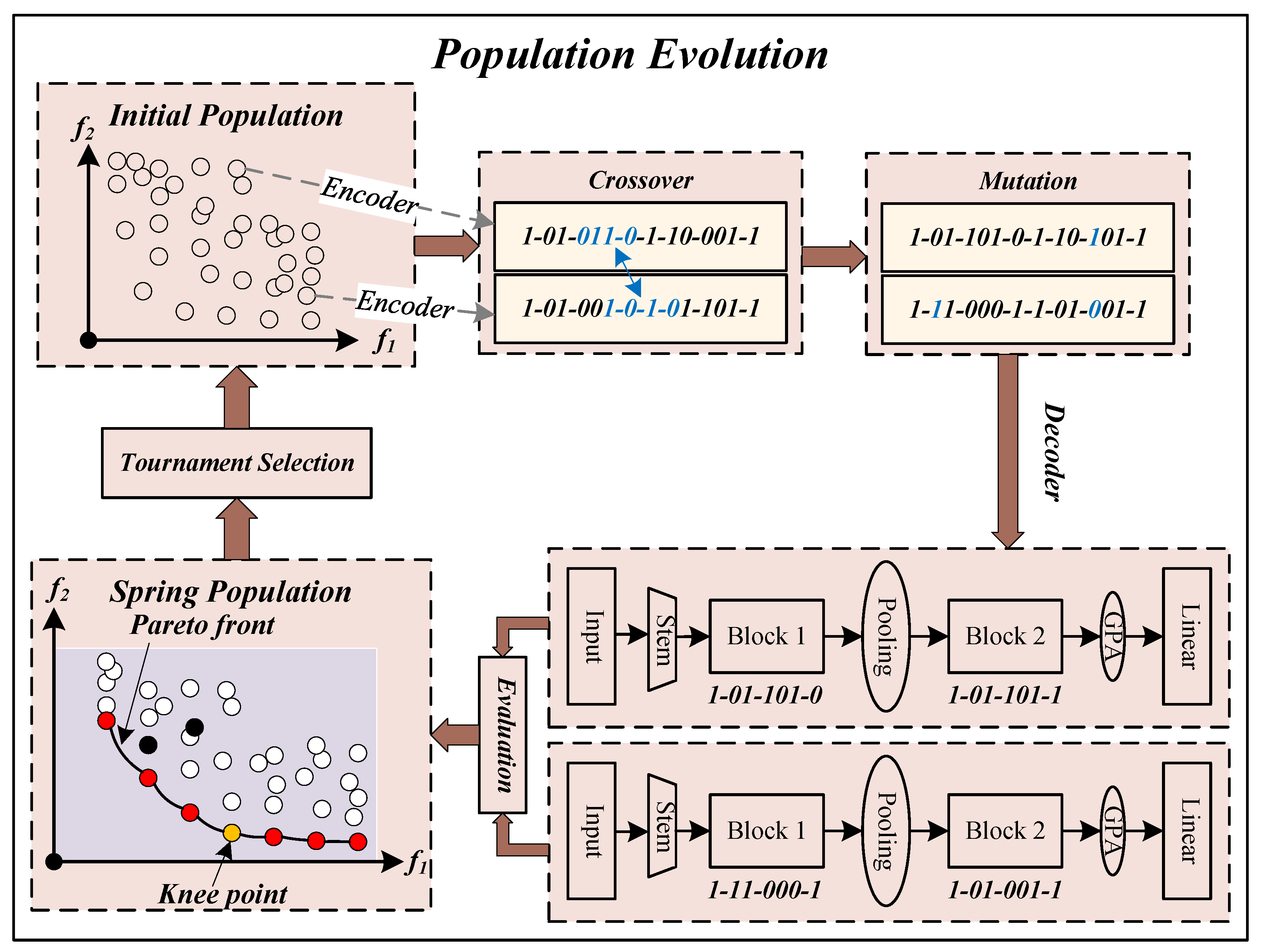
Figure 2 depicts a schematic diagram of population evolution. Consistent with the paradigm of a genetic algorithm, the population evolution is primarily made up of crossover and mutation, evaluation, as well as selection. First, individuals in the initial population are randomly selected for crossover. Then, crossover and mutation operations are performed on the selected individuals to obtain offspring individuals. Finally, all new individuals are evaluated and a new generation population is selected. This process is looped until the stop condition is met. We describe crossover, mutation, evaluation, and environmental selection in detail below.
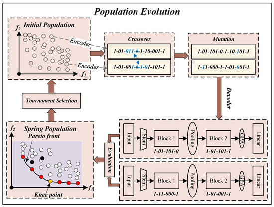
Figure 2.
The diagram of population evolution in TPENAS. Stem represents a convolution operation; Block represents a feature extraction block; Pooling represents a pooling operation; GPA represents a global average pooling operation; Linear represents a fully connected layer.
- (1)
- Crossover and MutationCrossover and mutation operations are used to generate better-quality individuals, which are common operations in genetic algorithms. We randomly pick two individuals from the population and perform a crossover on them with probability . The crossover operation involves selecting a continuous binary string of the same length from two individuals and generating two new individuals by exchanging the binary string segments. The two new individuals perform mutation operations respectively to generate new individuals. The mutation operation is practiced by inverting each binary bit with probability in turn. In the experiment, the crossover probability and mutation probability are set to pc and pm , respectively, where l represents the code length of the individual.
- (2)
- EvaluationIn the first search phase, we need to evaluate the overall classification accuracy and the length of the individual. To meet the minimum optimization problem, we use the overall classification error rate of the model on the testing dataset to evaluate the individual’s overall classification accuracy. We use the number of blocks to evaluate an individual’s length. Before evaluating an individual, we need to decode the binary string representing the individual into the corresponding CNN model. The model is trained on the training dataset and then tested on the testing dataset to obtain the overall classification error rate of the model. It is worth noting that in the whole optimization process, we save the binary code of the individual, the overall classification error rate, and the number of blocks of the model into the external population E, and, before evaluating each individual, we first query the individual in the set E. If it exists, the overall classification error rate of the individual and the number of blocks of the model are directly copied without retraining the model, which saves time in the first search phase.
- (3)
- Environmental SelectionWe select the offspring population by binary tournament selection. Specifically, two individuals are selected firstly from the parent population, and then the most suitable one from the two individuals is chosen and added to the offspring population. Repeat N times to select N individuals as the offspring population.
2.2.4. Solution Selection
To determine the optimal depth in the remote sensing image classification model, we first select the highest classification accuracy from individuals outputted by population evolution in Section 2.2.3. This will form the optimal solution front. Then, the knee point method [63] is used to select the optimal solution from the optimal solution front. Finally, we determine the optimal depth of the model by calculating the number of blocks in the optimal solution.
2.3. The Second Search Phase
During the second search phase, we explore the impact of the network’s structure on the classification accuracy of remote sensing images. We consider both classification accuracy and the complexity of the model. In the second search phase, we use the GFLOPs of the model to represent the complexity of the model. Similar to the first search phase, we build a multi-objective optimization problem using the classification error rate and GFLOPs of the model. Because the number of blocks and evaluation metrics of the individual in the second search phase differ from those in the first search phase, we can use the heuristic-based multi-objective optimization algorithm designed in the first search phase to solve the multi-objective optimization problem in the second search phase. Therefore, we can modify some parts of the first search phase to implement the second search phase process. There are three differences from the first search phase, as follows:
- (1)
- In the first search phase, we determine the optimal number of blocks of individuals. In the second search phase, we optimize the classification error rate and GFLOPs of the model and no longer optimize the block number of the model. Therefore, when initializing the population as in Section 2.2.2, M individuals with the same number of blocks are randomly initialized.
- (2)
- In the second search phase, the two optimization objectives are the classification error rate and GFLOPs of the model. Therefore, when evaluating individuals as in Section 2.2.3, we evaluate the individual’s classification error rate and calculate the individual’s GFLOPs.
- (3)
- We do not select the optimal individual from the final population as in Section 2.2.4. This is because we use the binary tournament selection method when choosing the offspring population, which may overlook some Pareto solutions. As a result, we aggregate all of the individuals from each generation into an external population and then select the Pareto front from .
As mentioned above in Section 2.1, we specifically set these two problems as multi-objective optimization problems and designed the TPENAS algorithm to solve these problems employing a genetic algorithm paradigm. TPENAS solves for the depth of the model in the first search phase and produces a set of solutions that balance overall accuracy and GFLOPs in the second search phase. The result of TPENAS in two phases is a set of solutions, and we can choose the appropriate one according to our practical needs.
3. Results
In this section, we discuss experimental details to validate TPENAS. Section 3.1 introduces the datasets used in the experiments. Section 3.2 describes the experimental settings. Section 3.3 shows the experimental results.
3.1. Datasets
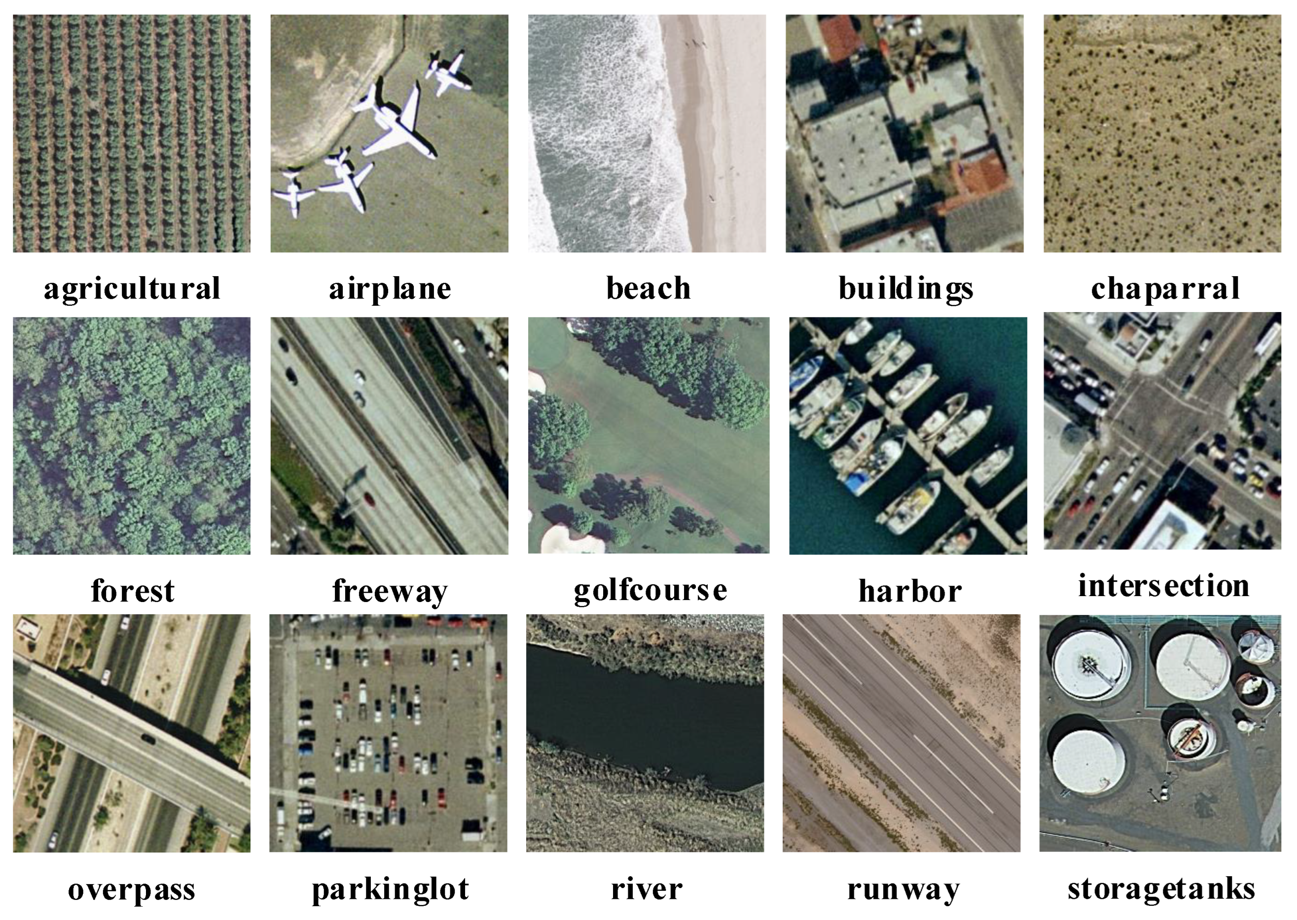
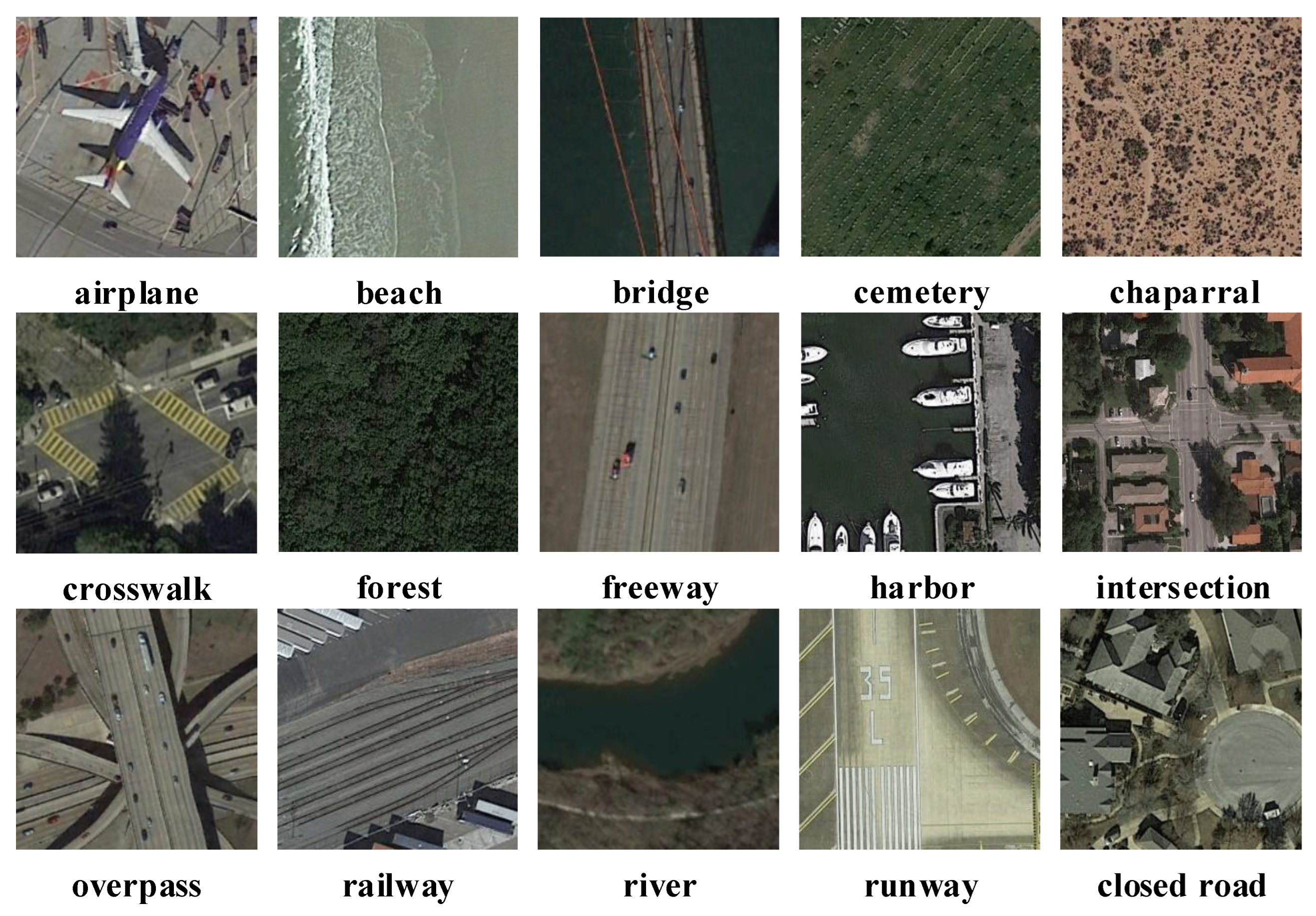
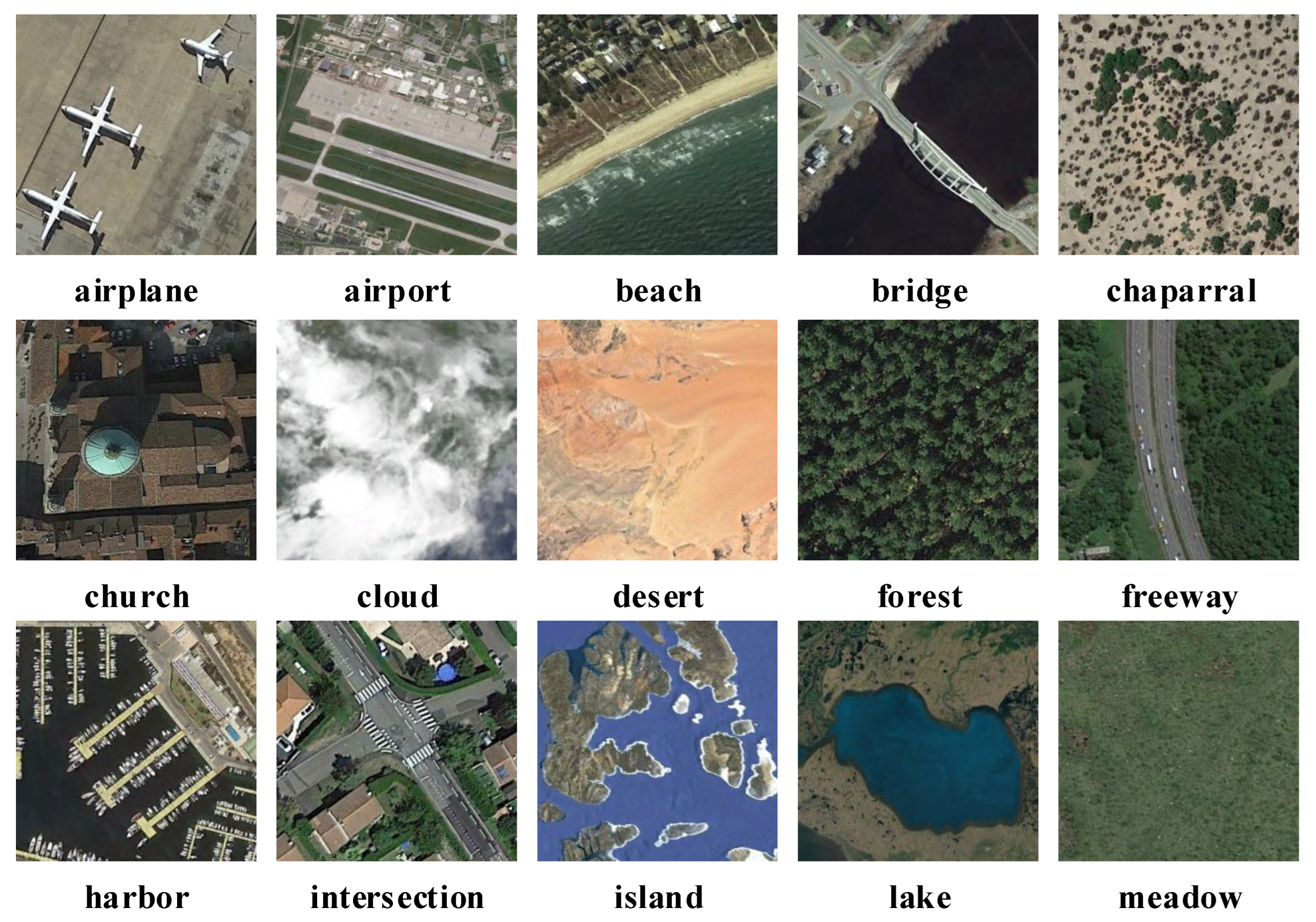
The proposed method is verified on three datasets, namely UCM21 [22], PatternNet [64], and NWPU45 [65] datasets. The characteristics of the three datasets are summarized in Table 1. Table 1 shows the three obvious characteristics of the three datasets. First, the large variation in the scene classes between the UCM21 dataset and NWPU45 dataset. The number of scenes in the NWPU45 dataset is more than double that of the UCM21 dataset. Second, the large variation in the size of the three datasets. NWPU45 datasets are 15 times larger than UCM21 datasets. PatternNet dataset has eight times the number of images per class as the UCM21 dataset. Third, the large variation in the spatial resolution of the three datasets.

Table 1.
Characteristics of the three datasets in our experiments.
The spatial resolution of the UCM21 dataset is fixed at 0.3 m. The spatial resolution of the PatternNet dataset has a small range of 4.63 m, while the NWPU45 dataset has a large range of 28.8 m. Some samples are shown from the three datasets in Figure 3, Figure 4 and Figure 5, respectively.
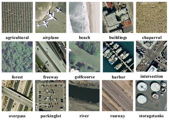
Figure 3.
Some samples from the UCM21 dataset.
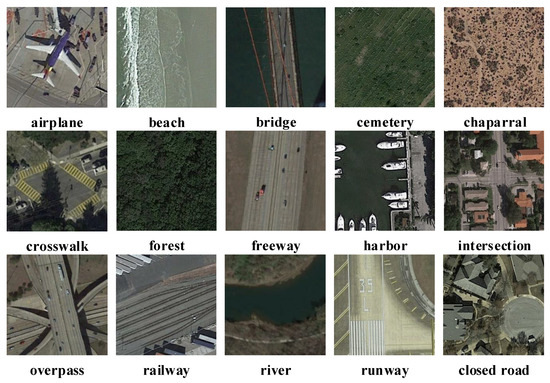
Figure 4.
Some samples from the PatternNet dataset.
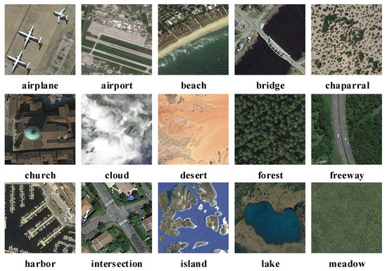
Figure 5.
Some samples from the NWPU45 dataset.
3.2. Experimental Settings
3.2.1. Parameter Setting
The experiment is divided into two parts. The first part is the search phase, including the first search phase and the second search phase. The second part is the retraining phase. The hyperparameters of the two parts are shown in Table 2. In total, 80%, 40%, and 20% of samples of the UCM21, PatternNet, and NWPU45 datasets are split into training datasets, and the rest are used as testing datasets. The hardware configuration and software version of the experimental environment are shown in Table 3.

Table 2.
Hardware configuration and software version of the experimental environment.

Table 3.
Hyperparameters of the proposed algorithm.
3.2.2. Evaluation Metrics
In order to evaluate the effectiveness of the proposed algorithm, we use the overall accuracy (OA) and confusion matrix (CM) as the evaluation metrics for the classification accuracy of the model and use the FLOPs and parameters (Params) as evaluation metrics to assess the computational cost and parameters of the remote sensing image classification model.
OA indicates the overall classification accuracy of the model, which represents the ratio of correctly classified samples to all samples in the testing dataset. OA and CM are calculated using Equations (4) and (5), respectively, where S and denote all samples and samples of category c in the testing dataset, respectively; K indicates the number of categories in the testing dataset; is the indicator function; denotes the remote sensing image classification model; x denotes the input sample; denotes the label of the category c sample. CM is a matrix with K rows and K columns. denotes the proportion of samples of category i misclassified as samples of category j among all samples of category i in the testing dataset.
We calculate FLOPs and Params by using Equations (6) and (7), where and denote the height and width of the input feature map, respectively; and denote the number of input channels and output channels of the convolution kernel, respectively; I and O denote the number of input and output nodes in the fully connected layer, respectively; k denotes the size of the convolution kernel.
3.3. Comparison of the Proposed TPENAS with Other Methods
3.3.1. Results on UCM21 Dataset
We conducted experiments on the UCM21 dataset, the first publicly available remote sensing image classification dataset.
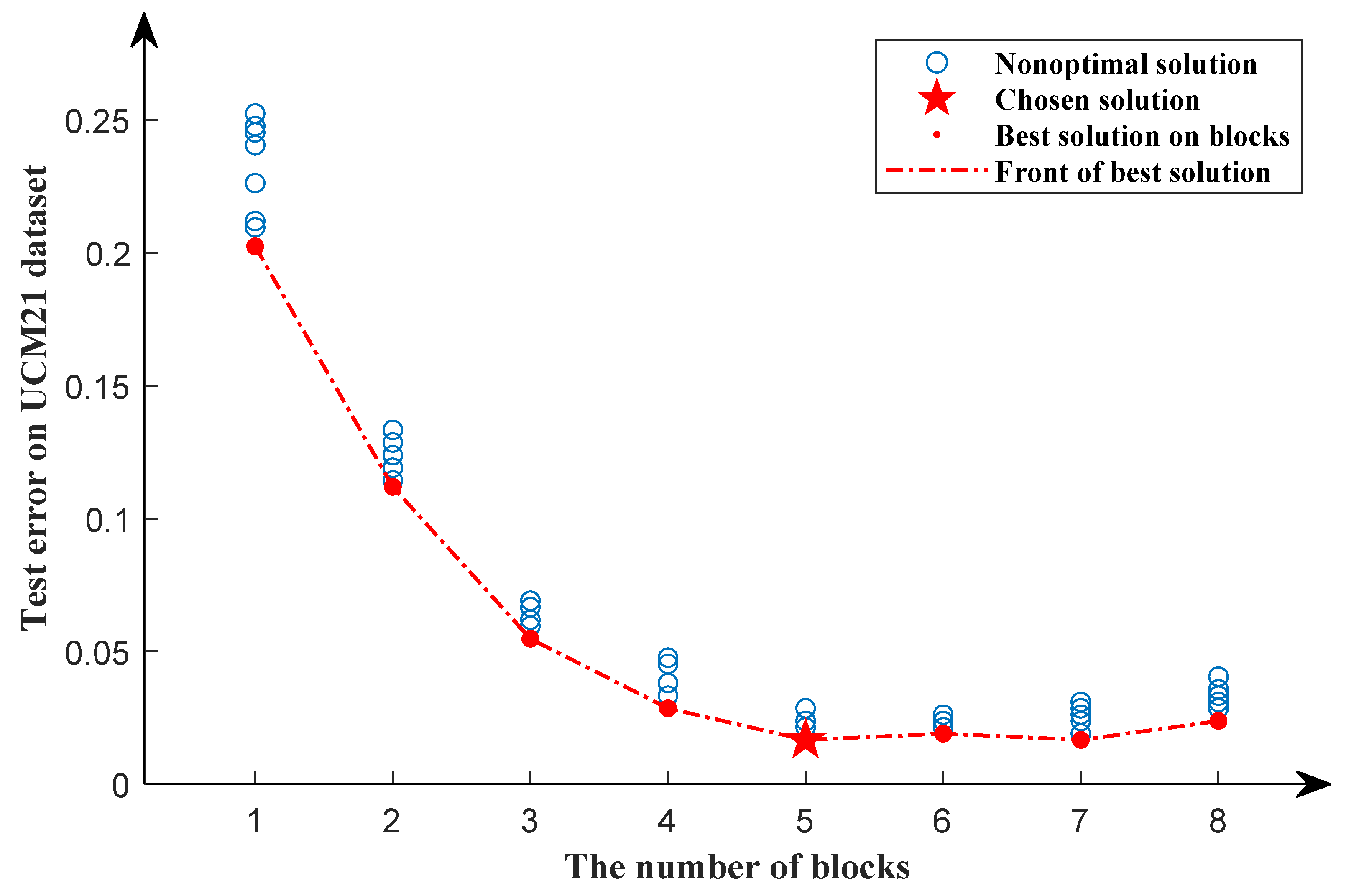
In the first search phase, 80% of data in the UCM21 dataset are randomly divided as the training dataset, and the rest as the testing dataset by a stratified sampling algorithm. The search results of the first search phase are shown in Figure 6. The red dotted line shows a downward trend as the number of blocks increases and stabilizes when the number of blocks equals five. We can see that as the number of blocks increases, the classificatin error rate of the model decreases. However, after the number of blocks is equal to five, the classificatin error rate of the model does not decrease significantly, but increases slightly. As a result, in the first search phase, the optimal solution is chosen when the number of blocks equals five.
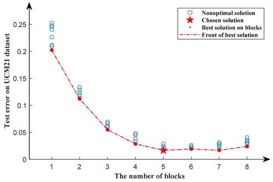
Figure 6.
Search results of the first search phase for the UCM21 dataset. The red dots represent the optimal solution in a particular block, while the blue circles represent nonoptimal solutions. The pentagram represents the chosen solution. The red dotted line represents the front of the best solution.
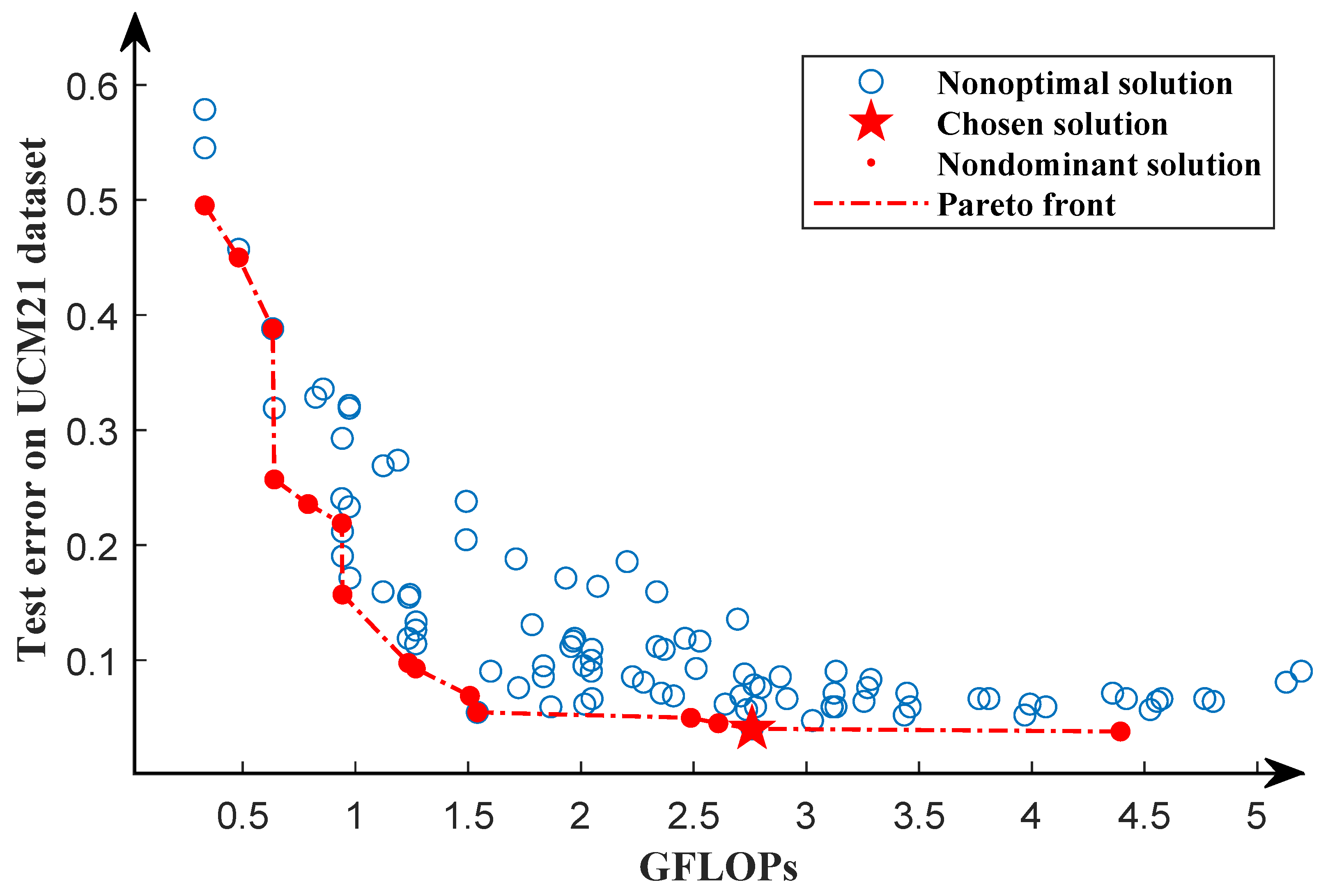
According to the optimal solution obtained in the first search phase, using the same training dataset and testing dataset as the first search phase, we further search for the structure of the network in the second search phase. Through the second search phase, we obtain the Pareto front, as shown in Figure 7. It can be seen from the Pareto front that the GFLOPs of the solution vary from 0.5∼4.5, which provides a variety of solutions. In order to select the model with the lowest classification error rate, we train each network in the Pareto solution set from scratch for 1000 epochs using the same dataset as the second search phase and select the individual with the lowest classification error as our chosen solution. Because the solutions in the Pareto solution set are only trained for 50 epochs, they are not fully trained. After full training, in the Pareto solution set, individuals with a high classification error rate may obtain a lower classification error rate than those with a low classification error rate. We will discuss this in Section 4.
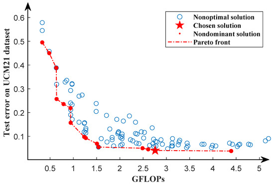
Figure 7.
Pareto front of the second search phase for the UCM21 dataset. The red dots represent the optimal solution, while the blue circles indicate the nonoptimal solutions. The Pareto front is represented by the red dotted line. The pentagram indicates the chosen solution.
In the retraining phase, we use five-fold cross-validation, with four folds as the training dataset and one fold as the testing dataset, to evaluate selected individuals. A total of 5 independent models are trained for 1000 epochs and tested, respectively. The average of the test accuracy of the five models is compared to other algorithms, including classic classification models such as AlexNet, VGG16, ResNet50, and others, as well as NAS-based methods such as NASNet, SGAS, DARTS, and so on. Additionally, we also compared their GFLOPs and Params, as shown in Table 4. Compared with classic classification models, TPENAS achieves the highest OA, and the GFLOPs are only higher than AlexNet, while the parameters are significantly lower than other models. Compared with NAS-based methods, the OA of TPENAS is 9.91% higher than NASNet and 2.03% higher than RSNet, and the parameters of TPENAS are at least half lower than those of NASNet, SGAS, and DARTS.

Table 4.
The OA, GFLOPs, and Params of TPENAS are compared with the other methods on the UCM21 dataset (the ratio of training samples to test samples is 8:2). The upward arrow (↑) indicates that the larger the number, the better the result. The downward arrow (↓) indicates that the smaller the number, the better the result.
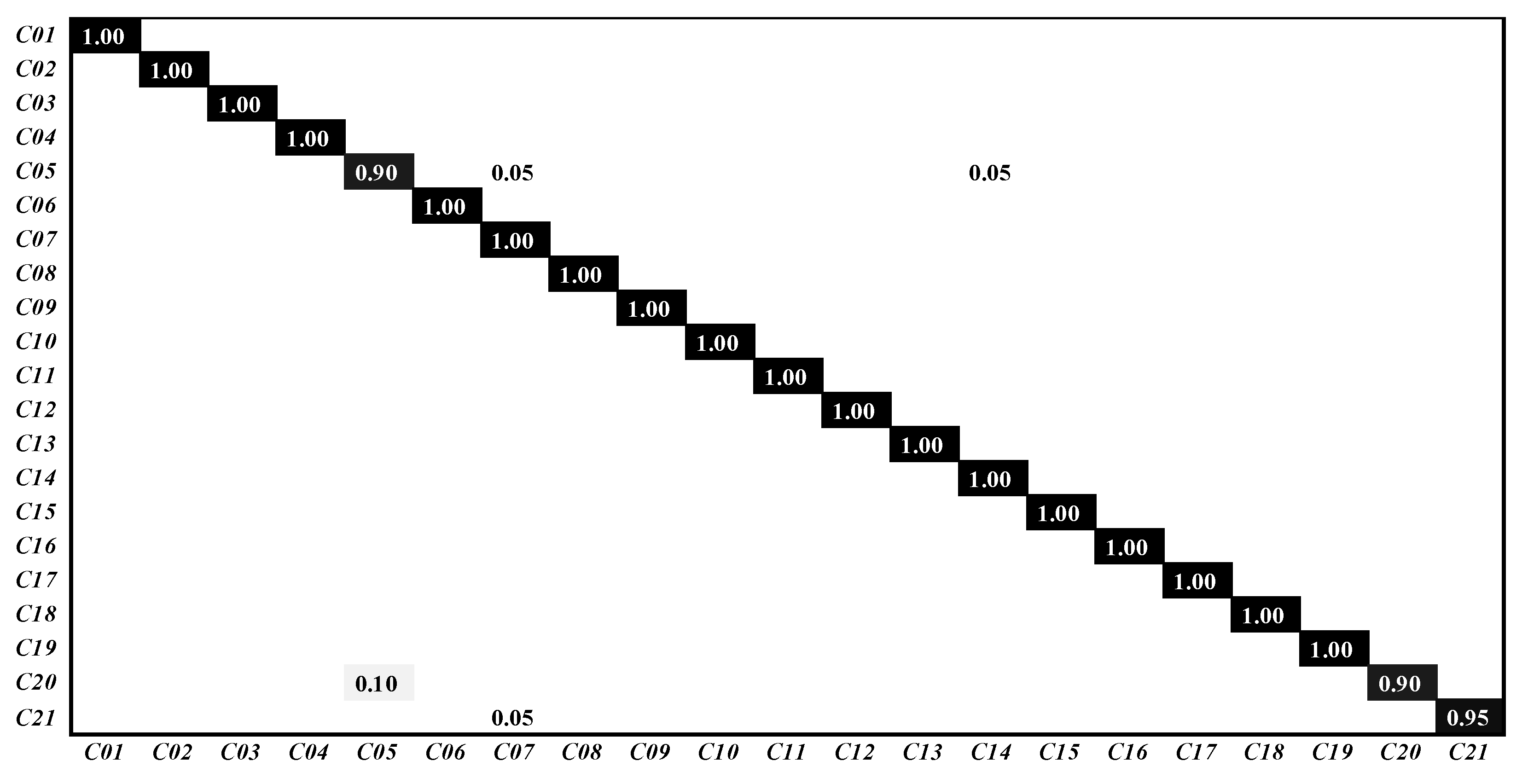
The classification confusion matrix are shown in Figure 8. C01∼C21 represent the categories agricultural, airplane, baseball diamond, beach, buildings, chaparral, dense residential, forest, freeway, golf course, harbor, intersection, medium residential, mobile home park, overpass, parking lot, river, runway, sparse residential, storage tanks and tennis court, respectively. The classification accuracy of TPENAS in the scenes “buildings” and “storage tanks” is 90%, the classification accuracy of “tennis court” is 95%, and the other scenes are 100%, which proves the excellent performance of our proposed algorithm.
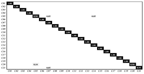
Figure 8.
The classification confusion matrix on UCM21 dataset.
3.3.2. Result on PatternNet Dataset
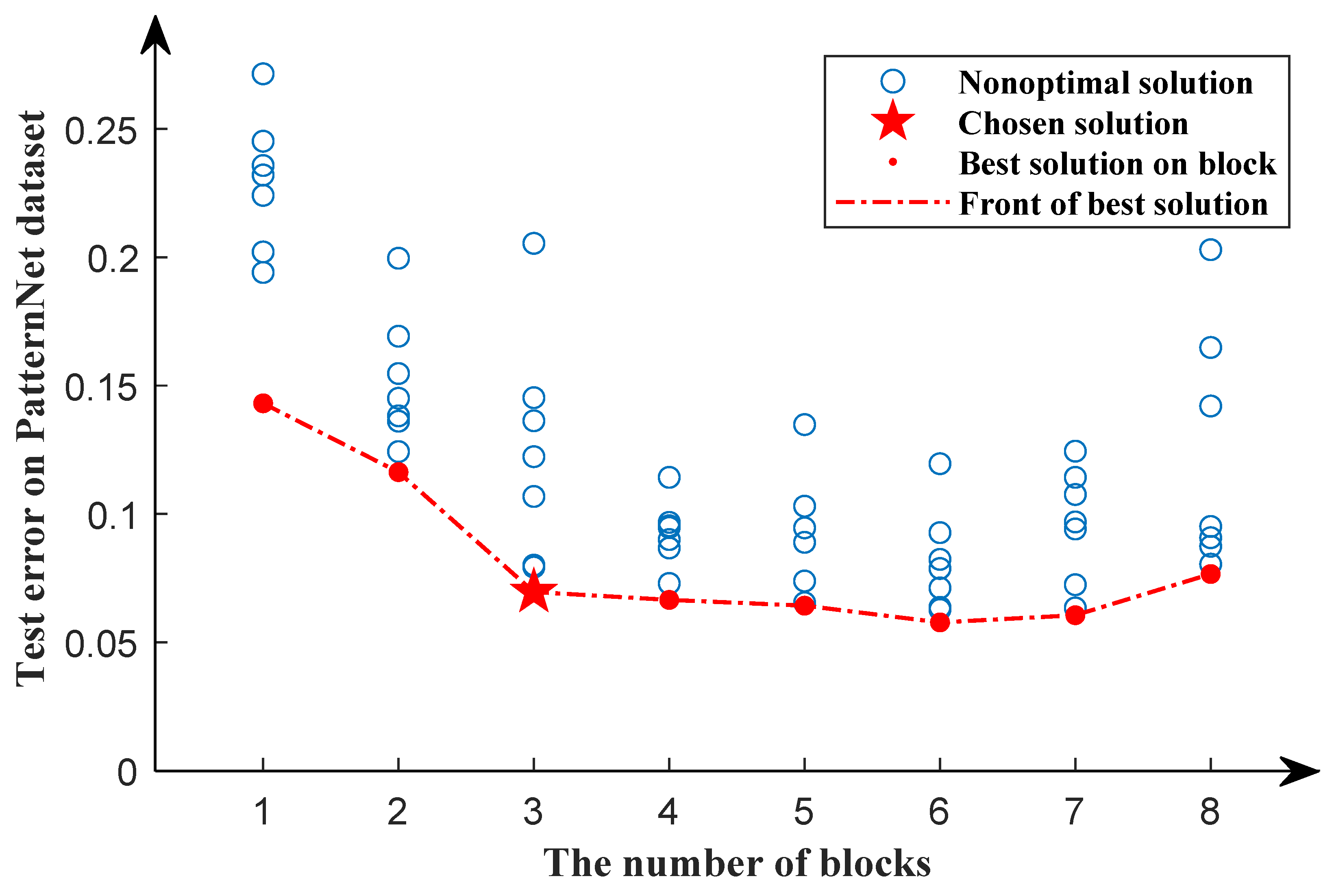
To further verify the performance of TPENAS, we validate experiments on the PatternNet dataset, which contains more scenes and more samples than the UCM21 dataset. During the first search phase, 40% of the data is selected at random as the training dataset and the remainder as the testing dataset. Figure 9 shows the search results in the first search phase. We can see that as the number of blocks increases, the red dotted line gradually decreases and flattens out after block equals 3. This demonstrates that as the number of blocks increases, the classification error rate of the model gradually decreases. However, when the number of blocks exceeds 3, the classification error rate of the model does not decrease significantly. As a result, the individual’s block in the second search phase is set to 3. On the UCM21 dataset, the optimal number of blocks in the first search phase is 5. It demonstrates that the optimal number of blocks for the model varies depending on the dataset.
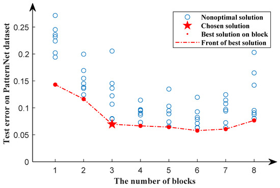
Figure 9.
Search results of the first search phase for the PatternNet dataset. The red dots indicate the optimal solution in a particular block, while the blue circles indicate nonoptimal solutions. The pentagram represents the chosen solution. The red dotted line represents the front of the best solution.
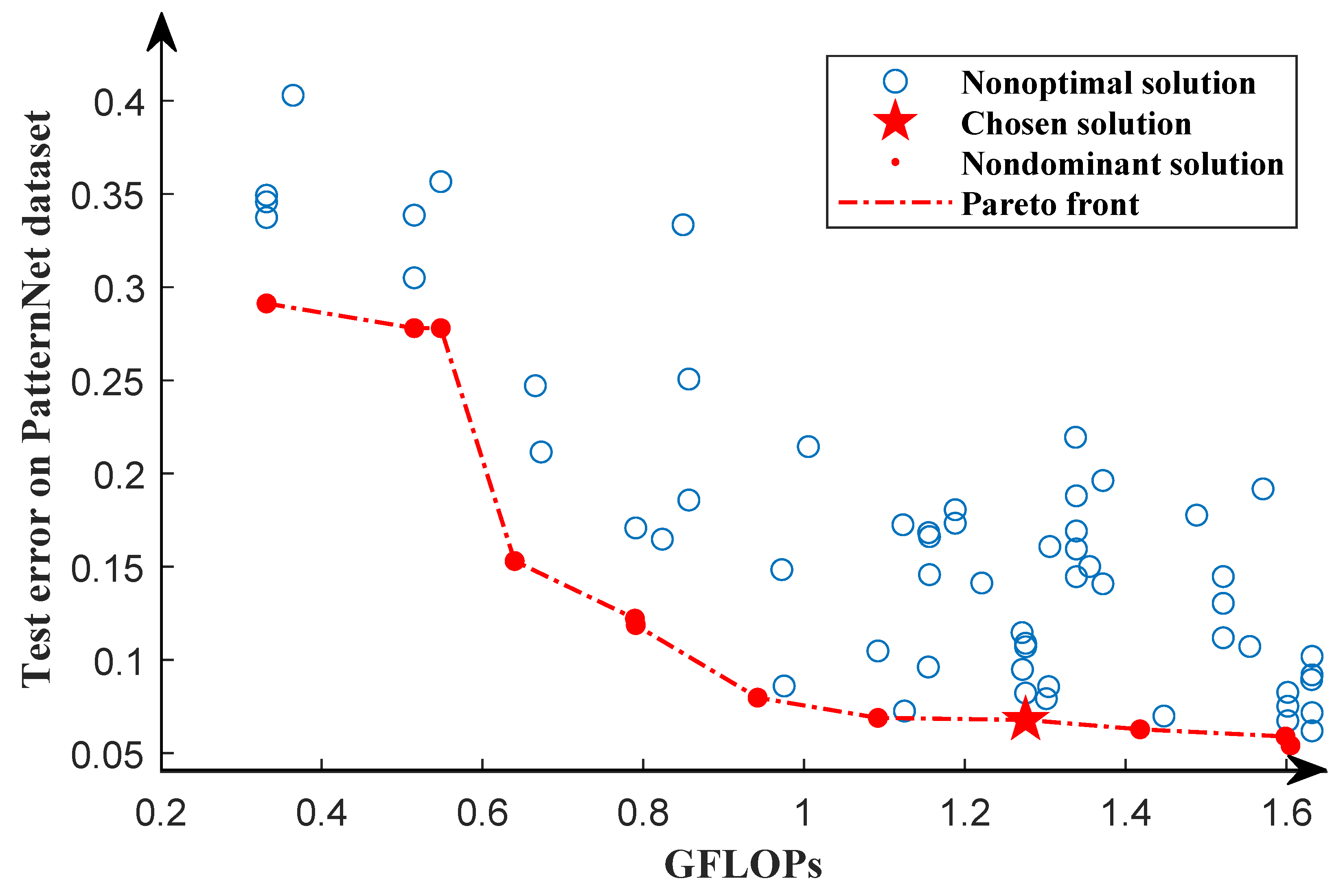
We searched the architecture of the model in the second search phase using the same dataset as the first search phase, and the result is shown in Figure 10. Each solution in the Pareto solution set has a unique network structure, and each solution in the Pareto solution set dominates at least one nonoptimal solution. Therefore, the second search phase is able to provide multiple models for remote sensing images classification. Each solution in the Pareto solution set is trained from scratch for 1000 epochs. The solution with the highest classification accuracy in the testing dataset is chosen for comparison with other algorithms.
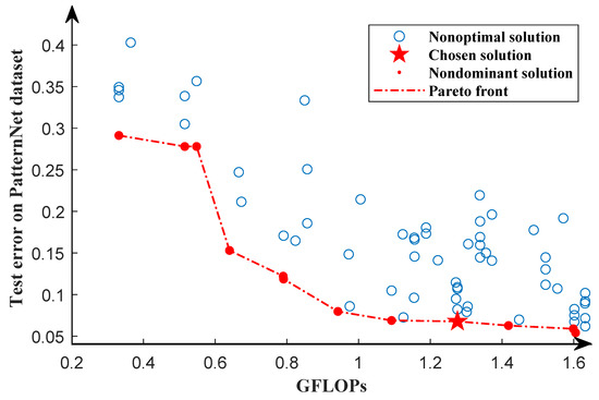
Figure 10.
Pareto front of the second search phase for the PatternNet dataset. The red dots represent the optimal solution, while the blue circles represent the nonoptimal solution. The Pareto front is represented by the red dotted line. The pentagram indicates the chosen solution.
During the retraining phase, 40% of the data in the PatternNet dataset is randomly selected to train the selected solutions from scratch and tested on the remaining 60% of the data. The experiment was repeated 5 times and the average overall accuracy was calculated, and the result is shown in Table 5. The OA of TPENAS is higher than classic classification models. Compared with NAS-based methods, the OA of TPENAS is higher than other algorithms, except that it is slightly lower than PDARTS. TPENAS has lower GFLOPs than classic classification models and roughly twice the GFLOPs of NAS-based methods. It is worth noting that parameters of TPENAS is at least one-twentieth of the classic classification models and NAS-based methods.

Table 5.
The OA, GFLOPs, and Params of TPENAS are compared with the other methods on the PatternNet dataset (the ratio of training samples to test samples is 4:6). The upward arrow (↑) indicates that the larger the number, the better the result. The downward arrow (↓) indicates that the smaller the number, the better the result.
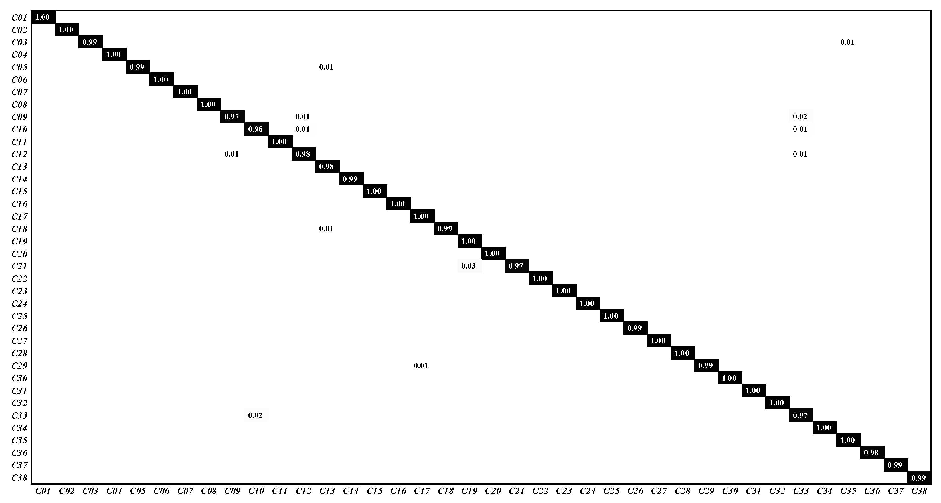
The confusion matrix is shown in Figure 11. C01∼C38 represent airplane, baseball field, basketball court, beach, bridge, cemetery, chaparral, christmas tree farm, closed road, coastal mansion, crosswalk, dense residential, ferry terminal, football field, forest, freeway, golf course, harbor, intersection, mobile home park, nursing home, oil gas field, oil well, overpass, parking lot, parking space, railway, river, runway, runway marking, shipping yard, solar panel, sparse residential, storage tank, swimming pool, tennis court, transformer station and wastewater treatment plant, respectively. Each scene has a classification accuracy greater than 97%, and more than half of the scenes have a classification accuracy of 100%. The experimental results on the PatternNet dataset show that the proposed TPENAS method can find acceptable depth and structure of the CNN model.
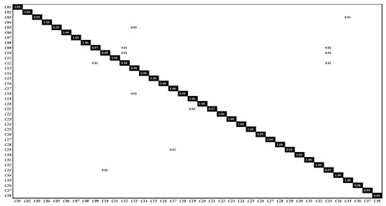
Figure 11.
The classification confusion matrix on PatternNet dataset.
3.3.3. Result on NWPU45 Dataset
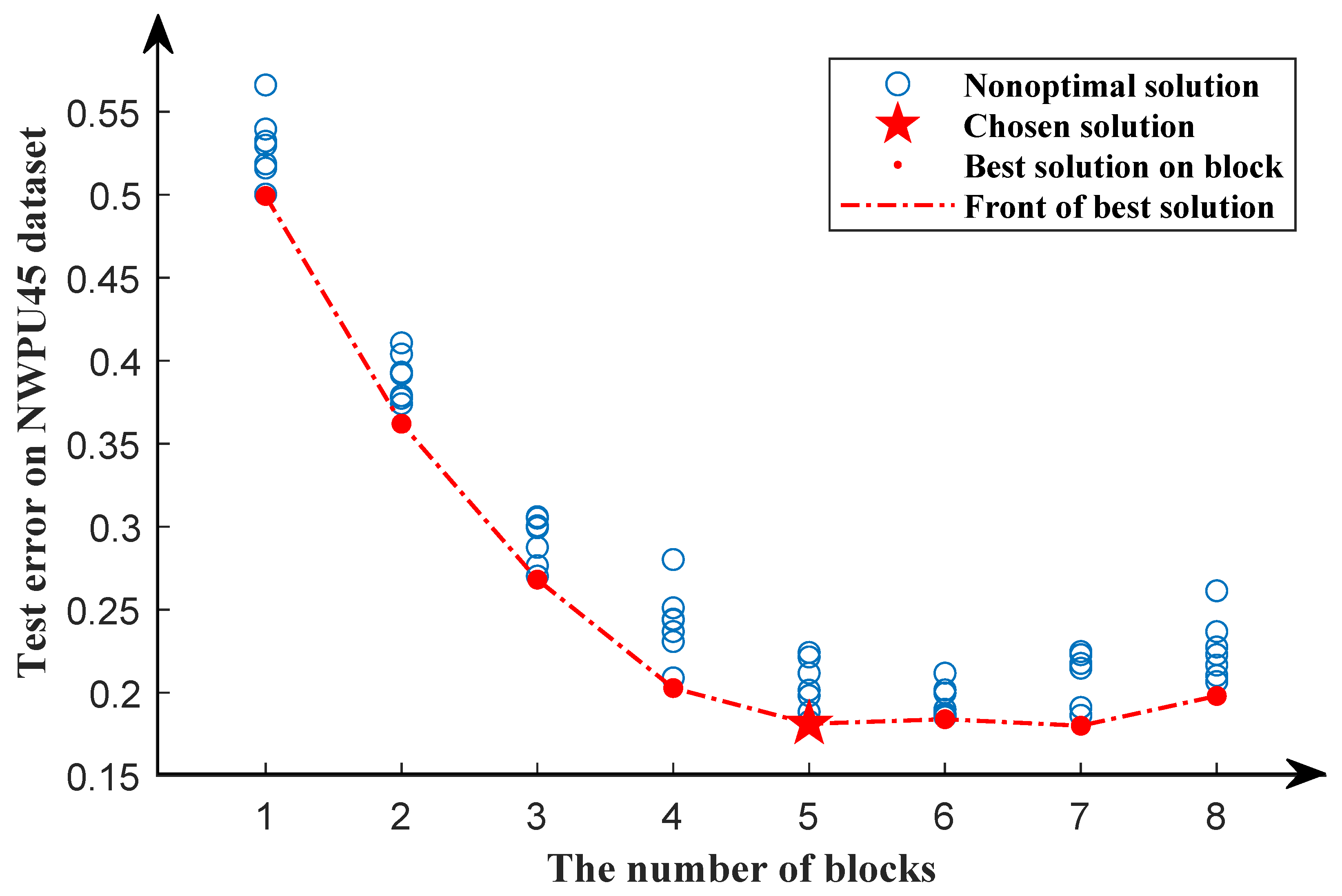
Following experiments on the UCM21 and PatternNet datasets, we tested the TPMEANS method on the NWPU45 dataset, which is currently the largest remote sensing image classification dataset. In the first search phase, 20% of the data are randomly selected as a training dataset, and the remaining 80% are used as a testing dataset. The results of the first search phase are shown in Figure 12.
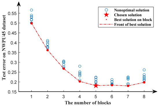
Figure 12.
Search results of the first search phase for the NWPU45 dataset. The red dots indicate the optimal solution in a particular block, while the blue circles indicate nonoptimal solutions. The pentagram represents the chosen solution. The red dotted line represents the front of the best solution.
Consistent with the experiments on the UCM21 dataset, the overall accuracy of the model decreases as the number of blocks increases until it reaches five. When the number of blocks exceeds five, the overall accuracy of the model becomes stable. As a result, we chose five blocks as the optimal individual length for the second search phase.
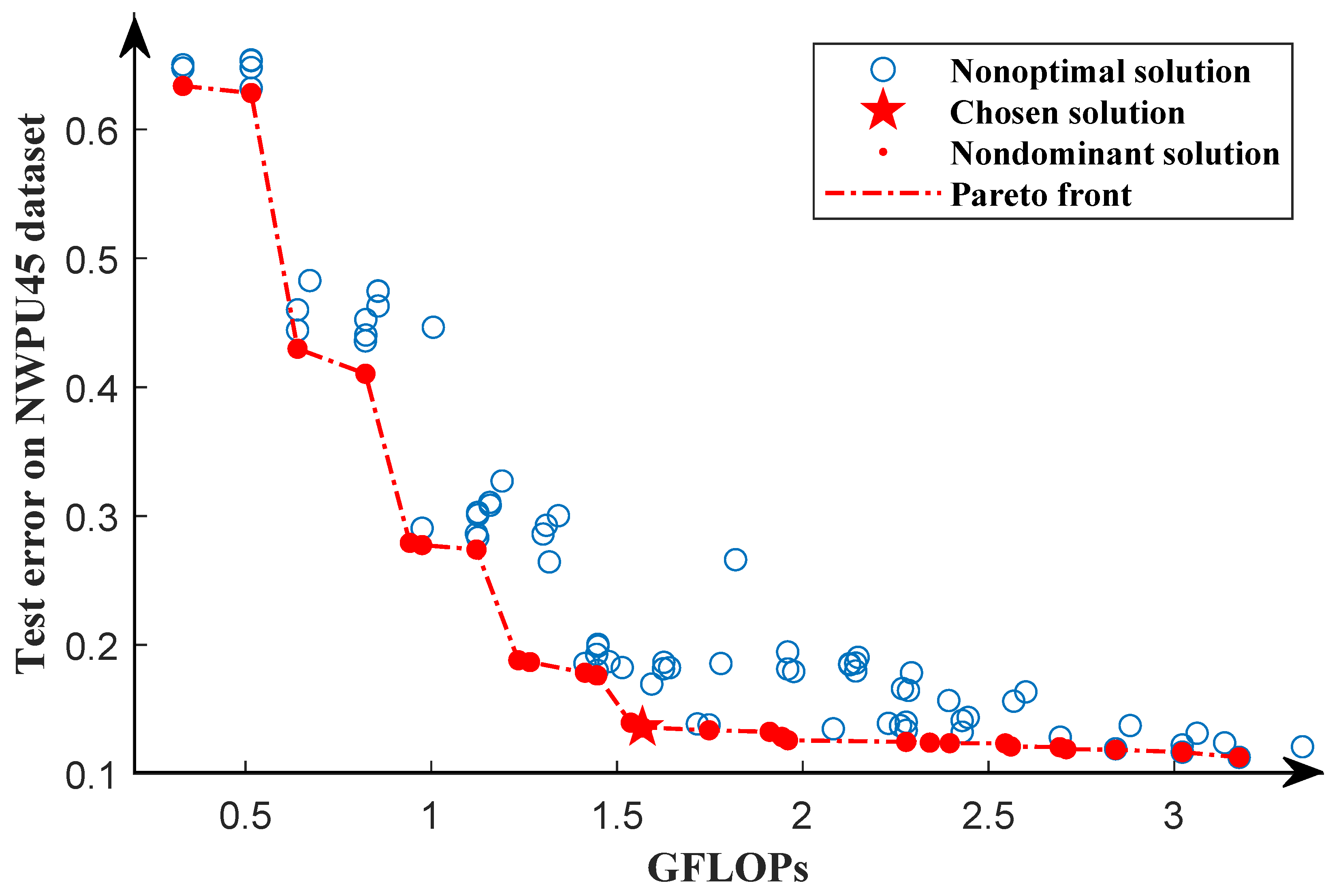
The second search phase is performed using the same dataset as the first search phase, and the obtained Pareto front is shown in Figure 13. The solutions in the Pareto solution set have different structures and are not superior to other solutions in the Pareto solution set in terms of GFLOPs and test error. This demonstrates that by running the algorithm once, we can generate multiple competing models for remote sensing image classification. Similar to the UCM21 dataset, we train all solutions from scratch for 1000 epochs and select the solution with the lowest test error to compare with other algorithms.
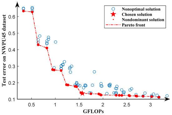
Figure 13.
Pareto front of the second search phase for the NWPU45 dataset. The red dots represent the optimal solution, while the blue circles represent the nonoptimal solutions. The Pareto front is represented by the red dotted line. The pentagram indicates the chosen solution.
In the retraining phase, we use five-fold cross-validation to evaluate the selected solutions. Different from the UCM21 dataset, we chose one fold as a training dataset and the remaining four folds as a testing dataset. A total of 5 independent models were trained from scratch for 1000 epochs, and their test results were averaged. We also compare classic classification models and NAS-based methods, as shown in Table 6. TPENAS_large denotes that the solution with the highest classification accuracy is selected from the Pareto solution set, and TPENAS_small denotes that the solution selected from the Pareto solution has higher classification accuracy and fewer parameters than other NAS-based models. The OA of TPENAS_large is 90.38%, which is better than both classic classification models and NAS-based methods. The GFLOPs of TPENAS_large are lower than VGG16, GoogleNet, and ResNet50, and slightly higher than AlexNet. With the exception of the RTRMM method, the parameters of TPENAS_large are significantly lower than those of classic classification models such as AlexNet and VGG16 and are at least half that of other NAS-based methods. Table 6 shows that the parameters of TPENAS_small are half that of RTRMM and the OA is higher than that of NAS-based methods.

Table 6.
The OA, GFLOPs, and Params of TPENAS are compared with the other methods on the NWPU45 dataset (the ratio of training samples to test samples is 2:8). The upward arrow (↑) indicates that the larger the number, the better the result. The downward arrow (↓) indicates that the smaller the number, the better the result.
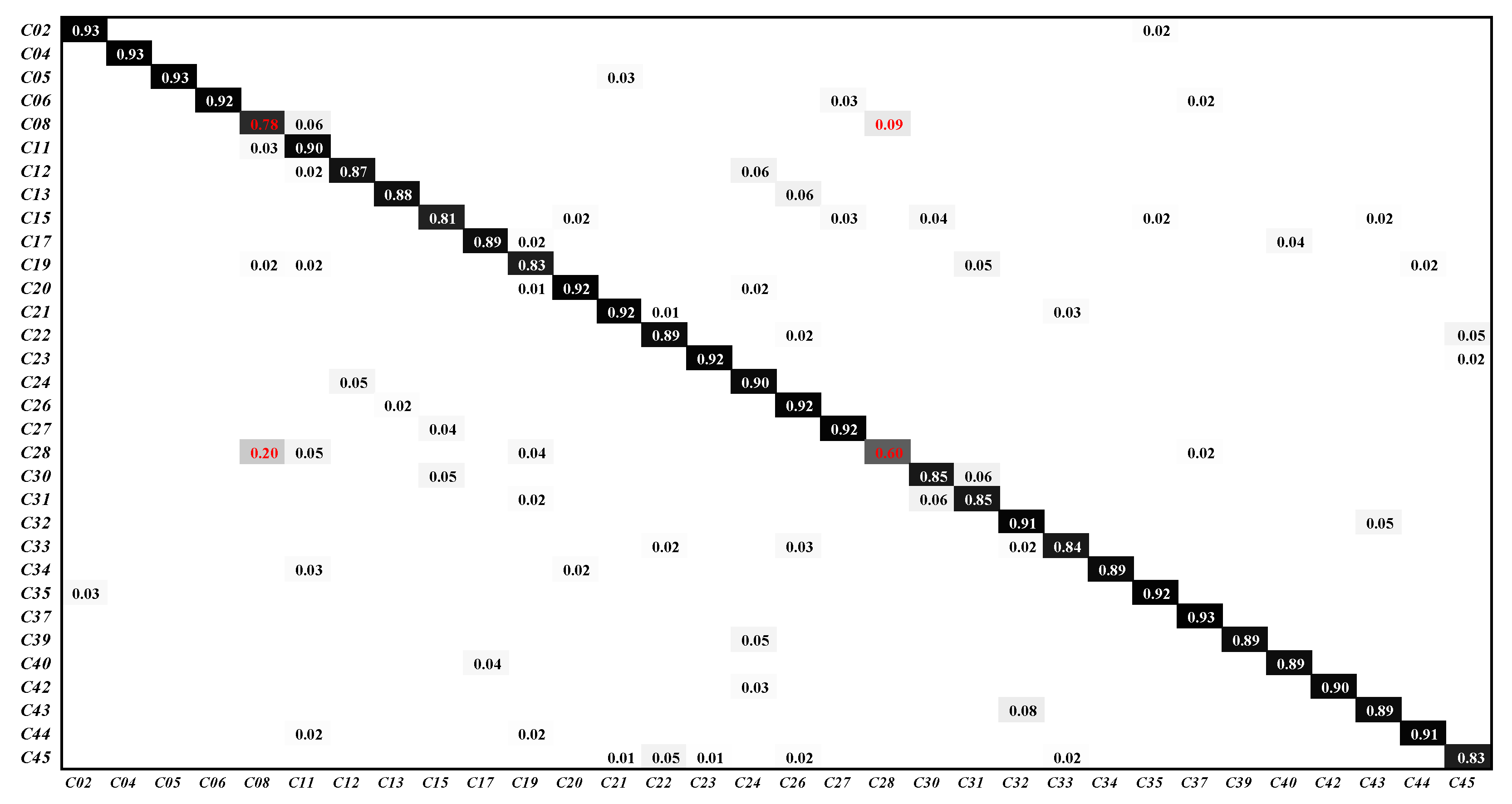
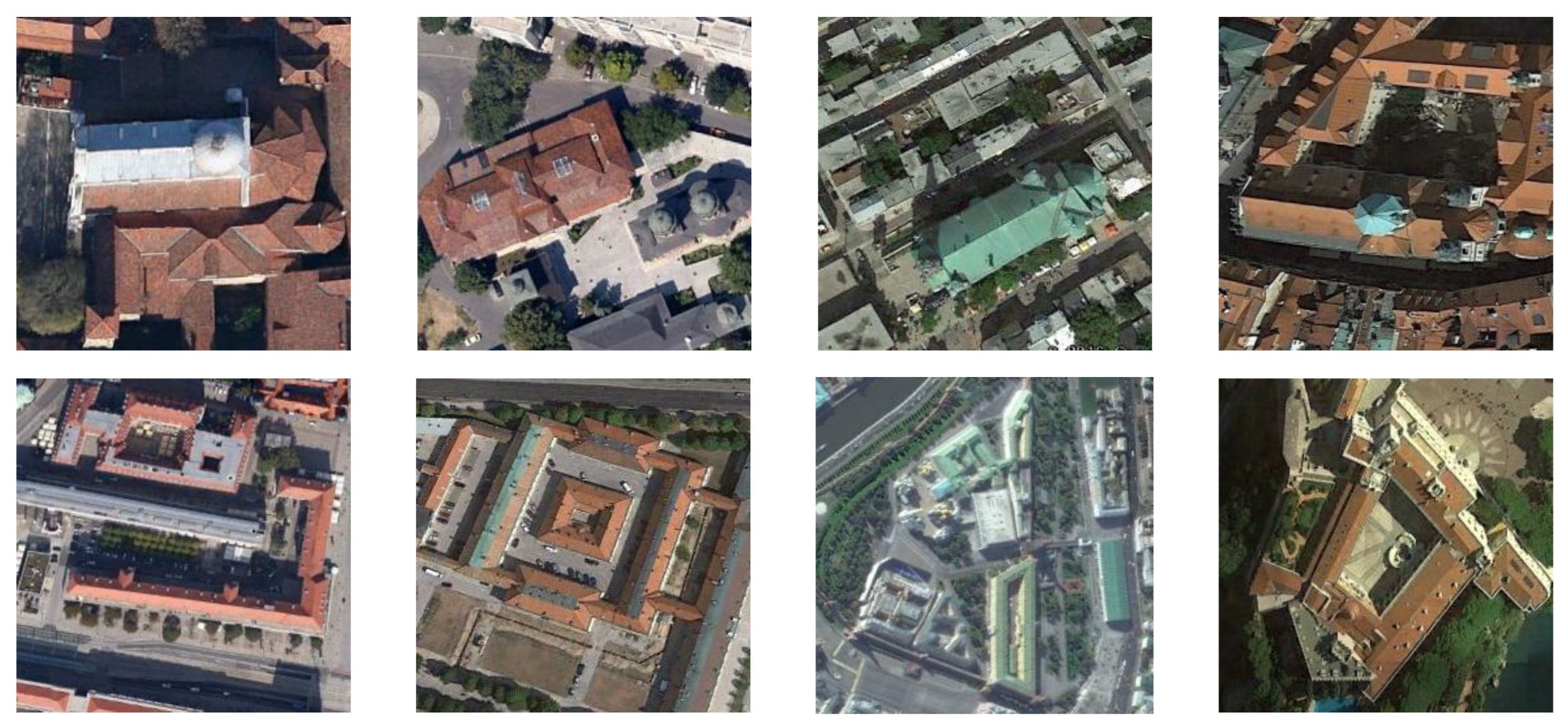
Figure 14 depicts the classification confusion matrix. C01∼C45 represent airplane, airport, baseball diamond, basketball court, beach, bridge, chaparral, church, circular farmland, cloud, commercial area, dense residential, desert, forest, freeway, golf course, ground track field, harbor, industrial area, intersection, island, lake, meadow, medium residential, mobile home park, mountain, overpass, place, parking lot, railway, railway station, rectangular farmland, river, roundabout, runway, sea ice, ship, snow berg, sparse residential, stadium, storage tank, tennis court, terrace, thermal power station and wetland, respectively. As shown in Figure 14, 20% of the place images are misclassified as church images and 9% of the church images are misclassified as place images. As shown in Figure 15, the category church is very similar to the category place, making it extremely difficult for the model to extract discriminative features from these images. TPENAS achieves high classification accuracy in other categories.
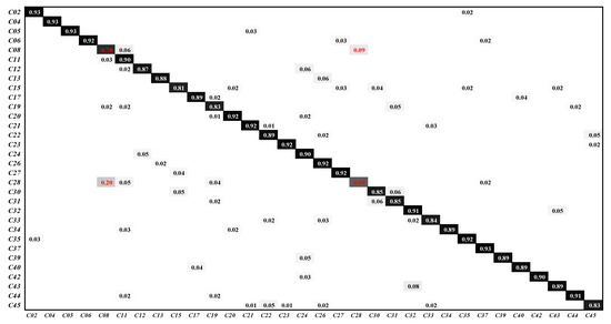
Figure 14.
The classification confusion matrix on the NWPU45 dataset. We removed categories with classification accuracy higher than 95% in the confusion matrix and did not display numbers less than 0.01.
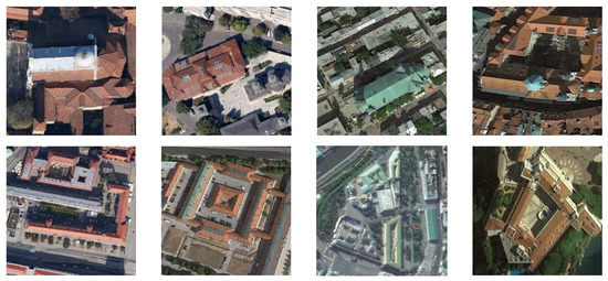
Figure 15.
Some samples in the categories church and place. The four images in the first row are in the category church, and the four images in the second row are in the category place.
3.3.4. Compared to Other CNN-Based Methods
Our proposed method is compared with other CNN-based remote sensing image classification methods, as shown in Table 7. The OA of TPENAS is higher than other CNN-based methods, which shows that the OA of our algorithm on remote sensing image classification tasks is satisfactory.

Table 7.
The OA of TPENAS is compared with the other CNN-based methods on the UCM21 dataset and NWPU45 dataset (the ratio of training samples to test samples is 8:2).
3.3.5. Compared to Other ENAS Methods
TPENAS was compared with other ENAS methods, as shown in Table 8. On the NWPU45 dataset, SceneNet, E2SCNet, and TPENAS were all trained using 80% of the dataset and then tested on the remaining 20% of the dataset. Experimental results show that our algorithm has a higher OA than SceneNet and E2SCNet, and that Params and GFLOPs are not the worst among the three algorithms.

Table 8.
The OA, Params, and GFLOPs of TPENAS are compared with the ENAS methods on the NWPU45 dataset (the ratio of training samples to test samples is 8:2). The upward arrow (↑) indicates that the larger the number, the better the result. The downward arrow (↓) indicates that the smaller the number, the better the result.
4. Discussion
4.1. Analysis of the Number of Evaluated Models
We compare the number of evaluated models for the proposed TPENAS and traversal search. In this paper, traversal search means that models with different numbers of blocks perform the second search phase respectively, and then the best model is selected from all the search results. In our experimental setup, the models have 8 different block numbers, so the traversal search needs to evaluate 32,000 models. TPENAS only needs to evaluate 4640 models. According to the current experimental settings, the number of models to be evaluated by TPENAS is , and the number of models to be evaluated by traversal search is , therefore, TPENAS evaluates fewer models than traversal search, where , and is the number of blocks that can be selected. It can be seen that as increases, increases linearly. This demonstrates that our algorithm is more time-efficient.
4.2. Analysis of the Depth of the Model in the Second Search Phase
The aim of the first search phase is to find the optimal depth of the model, which is the number of blocks of the model. We use the overall accuracy of the model and the number of blocks of the model as two optimization objectives to build a multi-objective optimization problem, as shown in Equation (1). The optimal solution to this optimization problem is the appropriate number of blocks. We designed the first search phase algorithm to optimize this optimization problem. On the UCM21 dataset, the number of blocks output by the first search phase algorithm is five, but this does not indicate an optimal solution to this optimization problem.
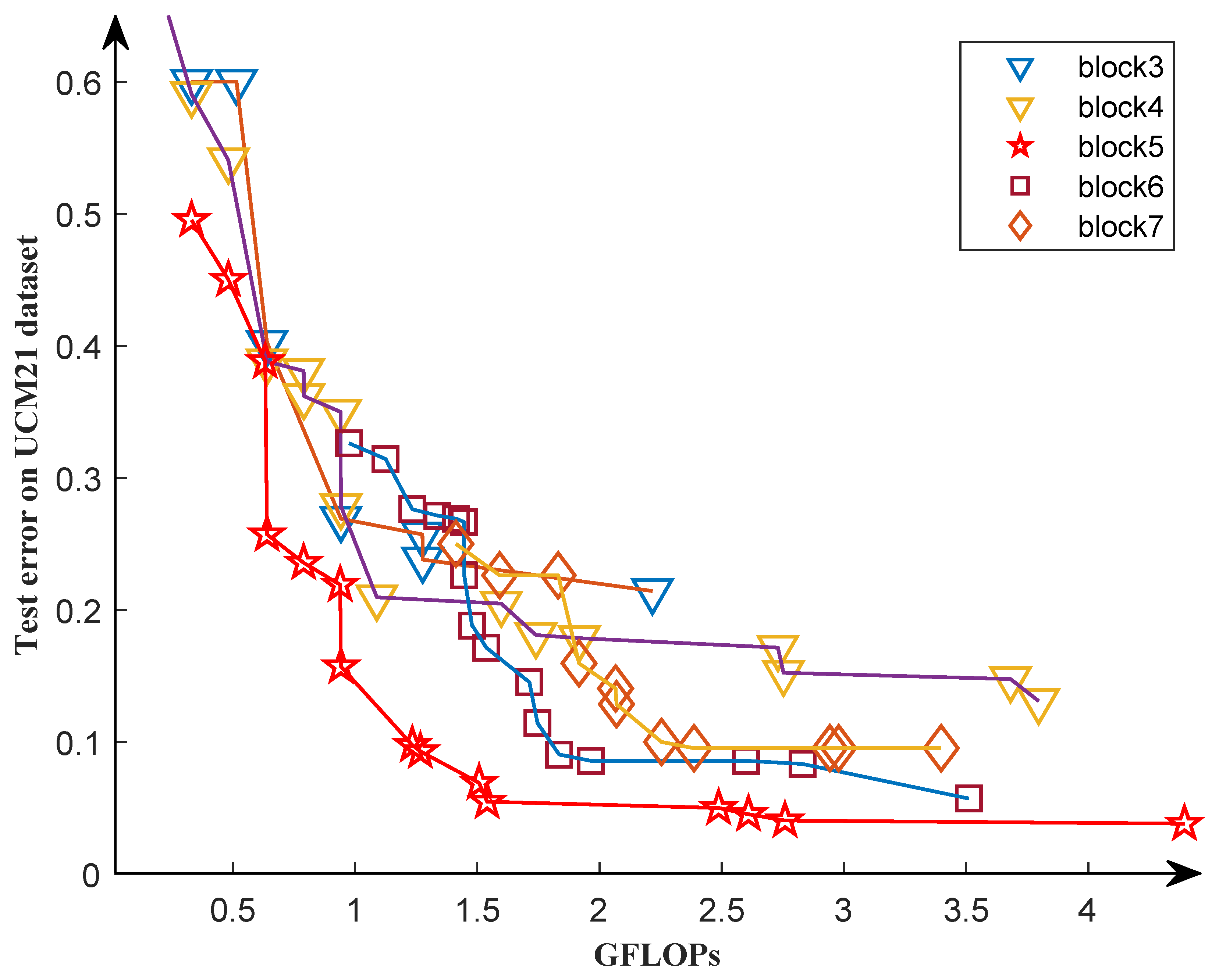
We selected five different block numbers to conduct ablation experiments on the UCM21 dataset to validate the effectiveness of the first search phase. Figure 16 shows the Pareto front of the experimental results. As we can see, it is not true that the greater the number of blocks, the better the Pareto front of the individual. For example, the Pareto front with seven blocks is worse than the Pareto front with six blocks, indicating that the former is superior. We discover that the Pareto front is optimal when the block equals five, which matches the results in our first search phase.
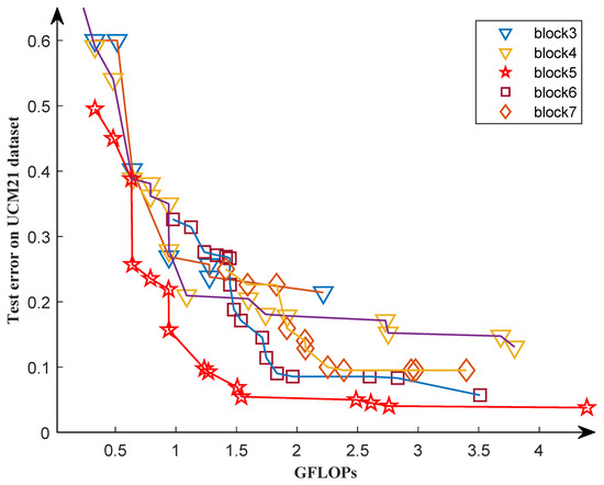
Figure 16.
The Pareto fronts obtained by experiments with five different block numbers during the second search phase.
4.3. Analysis of Fully Trained Models and Non-Fully Trained Models
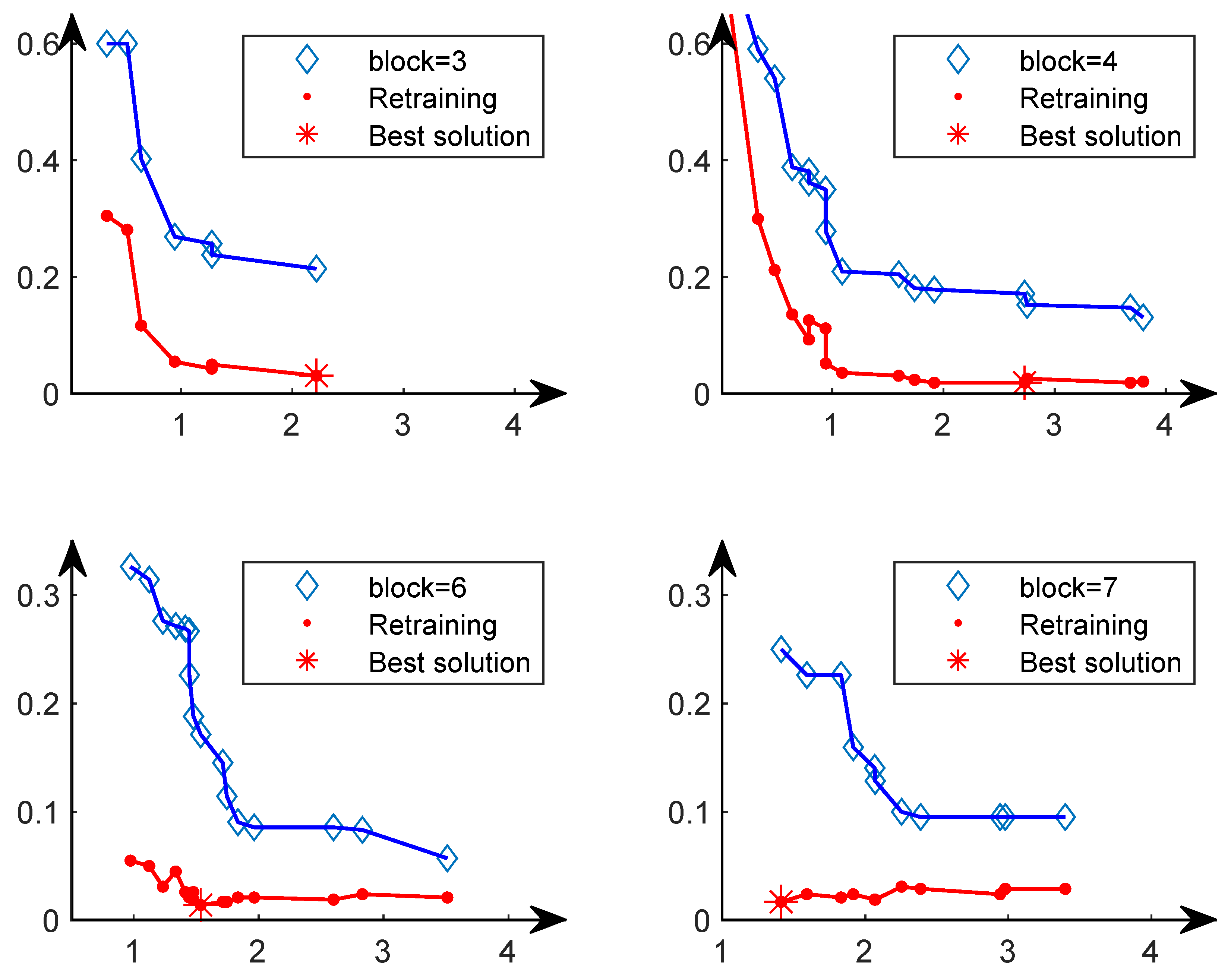
In the Pareto front obtained from the second search phase, we fully train each solution from scratch and then select the solution with the lowest classification error to compare with other methods. The reason is that after fully training from scratch, the solution with the lowest classification error may not be the solution with the lowest classification error in the Pareto solution set. Therefore, we conducted four sets of comparative experiments, as shown in Figure 17. In the upper left figure, after the solutions in the Pareto solution set with blocks equal to three are fully trained, the solution with the lowest classification error is the optimal solution in the Pareto set. However, the other three subplots show that after training completely from scratch, the solution with the lowest classification error is not the solution with the lowest classification error in the Pareto solution set. This further illustrates the rationality of our choice of the final solution.
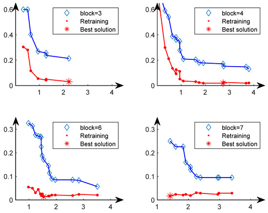
Figure 17.
The horizontal axis represents the GFLOPs of the individual, and the vertical axis represents the test error of the individual on the UCM21 dataset. The blue curve represents the Pareto front on the second phase. The red curve represents the result obtained by fully training the solution on the Pareto front from scratch.
4.4. Analysis of TPENAS Algorithm with Fewer Training Samples
Fewer training samples have two effects on the TPENAS algorithm. Firstly, it decreases the runtime of the TPENAS algorithm. Since the runtime of TPENAS is spent primarily on evaluating the model, reducing the training samples will linearly reduce the evaluation time of the model. Specifically, a -fold reduction in training samples will reduce the time to evaluate a single model by approximately a factor of . Furthermore, it also enables the algorithm to reduce its reliance on sample labels. Secondly, it is not conducive to TPENAS outputting well-structured models. This is because too few training samples will make the model easily overfitted during training. In the second search phase, the overfitted model will not evaluate the model accurately, resulting in low OA for well-structured individuals in the population. Therefore, a reasonable selection of the number of training samples is able to both reduce the running time of the TPENAS algorithm and search for structurally appropriate models. Such individuals can easily be eliminated in selecting the next-generation population, which leads to difficulties for the TPENAS algorithm to output a well-structured model.
5. Conclusions
In this paper, we propose TPENAS, a two-phase evolutionary neural architecture search for remote sensing image classification, which overcomes the shortcomings of manually designed CNN and NAS algorithms. In the first search phase, we optimize the classification accuracy and depth of the model to determine the maximum depth of the model on the benchmark dataset. In the second search phase, we optimize the classification accuracy and GFLOPs of the model to obtain a set of models for remote sensing image classification. The experimental results on the NWPU45 dataset show that TPENAS improves overall classification accuracy by 4.02% when compared to other NAS algorithms. Furthermore, it reduces the parameters by at least 13 times when compared to classic classification methods. In future work, we will explore how to design a more discriminative deep learning method to greatly promote the classification of similar images. In addition, in practical application scenarios, enough training samples can sometimes be difficult to obtain, and how to design high-accuracy remote sensing image classification models with small samples remains an open research question.
Author Contributions
Conceptualization, L.A. and K.F.; methodology, L.A. and K.F.; validation, L.A. and K.F.; investigation, L.A.; writing—original draft preparation, L.A. and K.F.; writing—review and editing, K.S., K.F., H.Z., X.H. and Z.C. All authors have read and agreed to the published version of the manuscript.
Funding
This work was supported by the National Key R&D program of China (No. 2022YFB4300700), Qin Chuangyuan cited the high-level innovative and entrepreneurial talent project (QCYRCXM-2022-21) and Guangdong High Level Innovation Research Institution Project (2021B0909050008).
Institutional Review Board Statement
Not applicable.
Informed Consent Statement
Not applicable.
Data Availability Statement
The NWPU-RESISC45 dataset used in this research is openly and freely available at https://1drv.ms/u/s!AmgKYzARBl5ca3HNaHIlzp$_$IXjs, accessed on 3 April 2017. The UC Merced Land-use dataset used in this research is openly and freely available at http://weegee.vision.ucmerced.edu/datasets/landuse.html, accessed on 28 October 2010. The PatternNet dataset used in this research is openly and freely available at https://sites.google.com/view/zhouwx/dataset, accessed on 25 May 2018.
Conflicts of Interest
The authors declare no conflict of interest.
References
- Gong, M.; Jiang, F.; Qin, A.K.; Liu, T.; Zhan, T.; Lu, D.; Zheng, H.; Zhang, M. A spectral and spatial attention network for change detection in hyperspectral images. IEEE Trans. Geosci. Remote Sens. 2022, 60, 5521614. [Google Scholar] [CrossRef]
- Gong, M.; Zhou, Z.; Ma, J. Change detection in synthetic aperture radar images based on image fusion and fuzzy clustering. IEEE Trans. Image Process. 2012, 21, 2141–2151. [Google Scholar] [CrossRef] [PubMed]
- Gong, M.; Zhao, J.; Liu, J.; Miao, Q.; Jiao, L. Change detection in synthetic aperture radar images based on deep neural networks. IEEE Trans. Neural Netw. Learn. Syst. 2016, 27, 125–138. [Google Scholar] [CrossRef]
- Liu, T.; Gong, M.; Lu, D.; Zhang, Q.; Zheng, H.; Jiang, F.; Zhang, M. Building change detection for VHR remote sensing images via local–global pyramid network and cross-task transfer learning strategy. IEEE Trans. Geosci. Remote Sens. 2022, 60, 4704817. [Google Scholar] [CrossRef]
- Gong, M.; Su, L.; Jia, M.; Chen, W. Fuzzy clustering with a modified MRF energy function for change detection in synthetic aperture radar images. IEEE Trans. Fuzzy Syst. 2014, 22, 98–109. [Google Scholar] [CrossRef]
- Wu, Y.; Li, J.; Yuan, Y.; Qin, A.; Miao, Q.G.; Gong, M.G. Commonality autoencoder: Learning common features for change detection from heterogeneous images. IEEE Trans. Neural Netw. Learn. Syst. 2021, 33, 4257–4270. [Google Scholar] [CrossRef] [PubMed]
- Castelluccio, M.; Poggi, G.; Sansone, C.; Verdoliva, L. Land use classification in remote sensing images by convolutional neural networks. arXiv 2015, arXiv:1508.00092. [Google Scholar]
- Zhu, Q.; Sun, Y.; Guan, Q.; Wang, L.; Lin, W. A weakly pseudo-supervised decorrelated subdomain adaptation framework for cross-domain land-use classification. IEEE Trans. Geosci. Remote Sens. 2022, 60, 5623913. [Google Scholar] [CrossRef]
- Pires de Lima, R.; Marfurt, K. Convolutional neural network for remote-sensing scene classification: Transfer learning analysis. Remote Sens. 2019, 12, 86. [Google Scholar] [CrossRef]
- Gong, M.; Li, J.; Zhang, Y.; Wu, Y.; Zhang, M. Two-path aggregation attention network with quad-patch data augmentation for few-shot scene classification. IEEE Trans. Geosci. Remote Sens. 2022, 60, 4511616. [Google Scholar] [CrossRef]
- Wang, Z.; Li, J.; Liu, Y.; Xie, F.; Li, P. An adaptive surrogate-assisted endmember extraction framework based on intelligent optimization algorithms for hyperspectral remote sensing images. Remote Sens. 2022, 14, 892. [Google Scholar] [CrossRef]
- Huang, X.; Wen, D.; Li, J.; Qin, R. Multi-level monitoring of subtle urban changes for the megacities of China using high-resolution multi-view satellite imagery. Remote Sens. Environ. 2017, 196, 56–75. [Google Scholar] [CrossRef]
- Li, Y.; Zhang, Y.; Huang, X.; Yuille, A.L. Deep networks under scene-level supervision for multi-class geospatial object detection from remote sensing images. ISPRS J. Photogramm. Remote Sens. 2018, 146, 182–196. [Google Scholar] [CrossRef]
- Longbotham, N.; Chaapel, C.; Bleiler, L.; Padwick, C.; Emery, W.J.; Pacifici, F. Very high resolution multiangle urban classification analysis. IEEE Trans. Geosci. Remote Sens. 2012, 50, 1155–1170. [Google Scholar] [CrossRef]
- Gong, M.; Liang, Y.; Shi, J.; Ma, W.; Ma, J. Fuzzy c-means clustering with local information and kernel metric for image segmentation. IEEE Trans. Image Process. 2012, 22, 573–584. [Google Scholar] [CrossRef]
- Wu, Y.; Ma, W.; Gong, M.; Su, L.; Jiao, L. A novel point-matching algorithm based on fast sample consensus for image registration. IEEE Geosci. Remote Sens. Lett. 2014, 12, 43–47. [Google Scholar] [CrossRef]
- Zhang, Y.; Gong, M.; Li, J.; Zhang, M.; Jiang, F.; Zhao, H. Self-supervised monocular depth estimation with multiscale perception. IEEE Trans. Image Process. 2022, 31, 3251–3266. [Google Scholar] [CrossRef]
- Li, H.; Li, J.; Zhao, Y.; Gong, M.; Zhang, Y.; Liu, T. Cost-sensitive self-paced learning with adaptive regularization for classification of image time series. IEEE J. Sel. Top. Appl. Earth Obs. Remote Sens. 2021, 14, 11713–11727. [Google Scholar] [CrossRef]
- Li, J.; Gong, M.; Liu, H.; Zhang, Y.; Zhang, M.; Wu, Y. Multiform ensemble self-supervised learning for few-shot remote sensing scene classification. IEEE Trans. Geosci. Remote Sens. 2023, 61, 4500416. [Google Scholar] [CrossRef]
- Perronnin, F.; Sánchez, J.; Mensink, T. Improving the fisher kernel for large-scale image classification. In Proceedings of the European Conference on Computer Vision, Crete, Greece, 5–11 September 2010; pp. 143–156. [Google Scholar]
- Lazebnik, S.; Schmid, C.; Ponce, J. Beyond bags of features: Spatial pyramid matching for recognizing natural scene categories. In Proceedings of the IEEE Computer Society Conference on Computer Vision and Pattern Recognition (CVPR’06), New York, NY, USA, 17–22 June 2006; pp. 2169–2178. [Google Scholar]
- Yang, Y.; Newsam, S. Bag-of-visual-words and spatial extensions for land-use classification. In Proceedings of the 18th SIGSPATIAL International Conference on Advances in Geographic Information Systems, San Jose, CA, USA, 2–5 November 2010; pp. 270–279. [Google Scholar]
- Zhang, F.; Du, B.; Zhang, L. Saliency-guided unsupervised feature learning for scene classification. IEEE Trans. Geosci. Remote Sens. 2015, 53, 2175–2184. [Google Scholar] [CrossRef]
- Cheng, G.; Han, J.; Guo, L.; Liu, T. Learning coarse-to-fine sparselets for efficient object detection and scene classification. In Proceedings of the IEEE Conference on Computer Vision and Pattern Recognition, Boston, MA, USA, 7–12 June 2015; pp. 1173–1181. [Google Scholar]
- Han, X.; Zhong, Y.; Zhao, B.; Zhang, L. Scene classification based on a hierarchical convolutional sparse auto-encoder for high spatial resolution imagery. Int. J. Remote Sens. 2017, 38, 514–536. [Google Scholar] [CrossRef]
- Shi, C.; Zhang, X.; Sun, J.; Wang, L. Remote sensing scene image classification based on self-compensating convolution neural network. Remote Sens. 2022, 14, 545. [Google Scholar] [CrossRef]
- Zhu, L.; Chen, Y.; Ghamisi, P.; Benediktsson, J.A. Generative adversarial networks for hyperspectral image classification. IEEE Trans. Geosci. Remote Sens. 2018, 56, 5046–5063. [Google Scholar] [CrossRef]
- Gu, S.; Zhang, R.; Luo, H.; Li, M.; Feng, H.; Tang, X. Improved singan integrated with an attentional mechanism for remote sensing image classification. Remote Sens. 2021, 13, 1713. [Google Scholar] [CrossRef]
- Miao, W.; Geng, J.; Jiang, W. Semi-supervised remote-sensing image scene classification using representation consistency siamese network. IEEE Trans. Geosci. Remote Sens. 2022, 60, 5616614. [Google Scholar] [CrossRef]
- Penatti, O.A.; Nogueira, K.; Dos Santos, J.A. Do deep features generalize from everyday objects to remote sensing and aerial scenes domains? In Proceedings of the IEEE Conference on Computer Vision and Pattern Recognition Workshops, Boston, MA, USA, 7–12 June 2015; pp. 44–51. [Google Scholar]
- Krizhevsky, A.; Sutskever, I.; Hinton, G.E. Imagenet classification with deep convolutional neural networks. In Advances in Neural Information Processing Systems 25; Curran Associates, Inc.: Red Hook, NY, USA, 2012. [Google Scholar]
- Simonyan, K.; Zisserman, A. Very deep convolutional networks for large-scale image recognition. arXiv 2014, arXiv:1409.1556. [Google Scholar]
- He, K.; Zhang, X.; Ren, S.; Sun, J. Deep residual learning for image recognition. In Proceedings of the IEEE Conference on Computer Vision and Pattern Recognition, Amsterdam, The Netherlands, 8–16 October 2016; pp. 770–778. [Google Scholar]
- Szegedy, C.; Liu, W.; Jia, Y.; Sermanet, P.; Reed, S.; Anguelov, D.; Erhan, D.; Vanhoucke, V.; Rabinovich, A. Going deeper with convolutions. In Proceedings of the IEEE Conference on Computer Vision and Pattern Recognition, Boston, MA, USA, 7–12 June 2015; pp. 1–9. [Google Scholar]
- Huang, G.; Liu, Z.; Van Der Maaten, L.; Weinberger, K.Q. Densely connected convolutional networks. In Proceedings of the IEEE Conference on Computer Vision and Pattern Recognition, Honolulu, HI, USA, 21–26 July 2017; pp. 4700–4708. [Google Scholar]
- Zhang, B.; Zhang, Y.; Wang, S. A lightweight and discriminative model for remote sensing scene classification with multidilation pooling module. IEEE J. Sel. Top. Appl. Earth Obs. Remote Sens. 2019, 12, 2636–2653. [Google Scholar] [CrossRef]
- Yu, D.; Guo, H.; Xu, Q.; Lu, J.; Zhao, C.; Lin, Y. Hierarchical attention and bilinear fusion for remote sensing image scene classification. IEEE J. Sel. Top. Appl. Earth Obs. Remote Sens. 2020, 13, 6372–6383. [Google Scholar] [CrossRef]
- Tong, W.; Chen, W.; Han, W.; Li, X.; Wang, L. Channel-attention-based densenet network for remote sensing image scene classification. IEEE J. Sel. Top. Appl. Earth Obs. Remote Sens. 2020, 13, 4121–4132. [Google Scholar] [CrossRef]
- Cheng, G.; Yang, C.; Yao, X.; Guo, L.; Han, J. When deep learning meets metric learning: Remote sensing image scene classification via learning discriminative CNNs. IEEE Trans. Geosci. Remote Sens. 2018, 56, 2811–2821. [Google Scholar] [CrossRef]
- Wang, C.; Tang, X.; Li, L.; Tian, B.; Zhou, Y.; Shi, J. IDN: Inner-class dense neighbours for semi-supervised learning-based remote sensing scene classification. Remote Sens. Lett. 2023, 14, 80–90. [Google Scholar] [CrossRef]
- Zoph, B.; Le, Q.V. Neural architecture search with reinforcement learning. arXiv 2016, arXiv:1611.01578. [Google Scholar]
- Baker, B.; Gupta, O.; Naik, N.; Raskar, R. Designing neural network architectures using reinforcement learning. arXiv 2016, arXiv:1611.02167. [Google Scholar]
- Zoph, B.; Vasudevan, V.; Shlens, J.; Le, Q.V. Learning transferable architectures for scalable image recognition. In Proceedings of the IEEE Conference on Computer Vision and Pattern Recognition, Salt Lake City, UT, USA, 18–22 June 2018; pp. 8697–8710. [Google Scholar]
- Real, E.; Moore, S.; Selle, A.; Saxena, S.; Suematsu, Y.L.; Tan, J.; Le, Q.V.; Kurakin, A. Large-scale evolution of image classifiers. In Proceedings of the International Conference on Machine Learning, Sydney, NSW, Australia, 6–11 August 2017; pp. 2902–2911. [Google Scholar]
- Xie, L.; Yuille, A. Genetic cnn. In Proceedings of the the IEEE International Conference on Computer Vision, Venice, Italy, 22–29 October 2017; pp. 1379–1388. [Google Scholar]
- Sun, Y.; Xue, B.; Zhang, M.; Yen, G.G. Evolving deep convolutional neural networks for image classification. IEEE Trans. Evol. Comput. 2020, 24, 394–407. [Google Scholar] [CrossRef]
- Liu, H.; Simonyan, K.; Yang, Y. Darts: Differentiable architecture search. arXiv 2018, arXiv:1806.09055. [Google Scholar]
- Xie, S.; Zheng, H.; Liu, C.; Lin, L. SNAS: Stochastic neural architecture search. arXiv 2018, arXiv:1812.09926. [Google Scholar]
- Tanveer, M.S.; Khan, M.U.K.; Kyung, C.M. Fine-tuning darts for image classification. In Proceedings of the IEEE International Conference on Pattern Recognition, Los Alamitos, CA, USA, 11–17 October 2021; pp. 4789–4796. [Google Scholar]
- Wu, Y.; Ding, H.; Gong, M.; Qin, A.; Ma, W.; Miao, Q.; Tan, K.C. Evolutionary multiform optimization with two-stage bidirectional knowledge transfer strategy for point cloud registration. IEEE Trans. Evol. Comput. 2022. [CrossRef]
- Li, J.; Li, H.; Liu, Y.; Gong, M. Multi-fidelity evolutionary multitasking optimization for hyperspectral endmember extraction. Appl. Soft Comput. 2021, 111, 107713. [Google Scholar] [CrossRef]
- Elsken, T.; Metzen, J.H.; Hutter, F. Simple and efficient architecture search for convolutional neural networks. arXiv 2017, arXiv:1711.04528. [Google Scholar]
- Chen, T.; Goodfellow, I.; Shlens, J. Net2net: Accelerating learning via knowledge transfer. arXiv 2015, arXiv:1511.05641. [Google Scholar]
- Zhu, H.; An, Z.; Yang, C.; Xu, K.; Zhao, E.; Xu, Y. EENA: Efficient evolution of neural architecture. In Proceedings of the IEEE/CVF International Conference on Computer Vision Workshops, Los Alamitos, CA, USA, 27–28 October 2019; pp. 1891–1899. [Google Scholar]
- Wang, B.; Sun, Y.; Xue, B.; Zhang, M. Evolving deep convolutional neural networks by variable-length particle swarm optimization for image classification. In Proceedings of the IEEE Congress on Evolutionary Computation, Rio de Janeiro, Brazil, 8–13 July 2018; pp. 1–8. [Google Scholar]
- Xie, X.; Liu, Y.; Sun, Y.; Yen, G.G.; Xue, B.; Zhang, M. BenchENAS: A benchmarking platform for evolutionary neural architecture search. IEEE Trans. Evol. Comput. 2022, 26, 1473–1485. [Google Scholar] [CrossRef]
- Zhang, Z.; Liu, S.; Zhang, Y.; Chen, W. RS-DARTS: A convolutional neural architecture search for remote sensing image scene classification. Remote Sens. 2021, 14, 141. [Google Scholar] [CrossRef]
- Peng, C.; Li, Y.; Jiao, L.; Shang, R. Efficient convolutional neural architecture search for remote sensing image scene classification. IEEE Trans. Geosci. Remote Sens. 2020, 59, 6092–6105. [Google Scholar] [CrossRef]
- Chen, J.; Huang, H.; Peng, J.; Zhu, J.; Chen, L.; Tao, C.; Li, H. Contextual information-preserved architecture learning for remote-sensing scene classification. IEEE Trans. Geosci. Remote Sens. 2022, 60, 5602614. [Google Scholar] [CrossRef]
- Ma, A.; Wan, Y.; Zhong, Y.; Wang, J.; Zhang, L. SceneNet: Remote sensing scene classification deep learning network using multi-objective neural evolution architecture search. ISPRS J. Photogramm. Remote Sens. 2021, 172, 171–188. [Google Scholar] [CrossRef]
- Wan, Y.; Zhong, Y.; Ma, A.; Wang, J.; Zhang, L. E2SCNet: Efficient multiobjective evolutionary automatic search for remote sensing image scene classification network architecture. IEEE Trans. Neural Netw. Learn. Syst. 2022; Early Access. [Google Scholar]
- Gudzius, P.; Kurasova, O.; Darulis, V.; Filatovas, E. AutoML-based neural architecture search for object recognition in satellite imagery. Remote Sens. 2022, 15, 91. [Google Scholar] [CrossRef]
- Zhang, X.; Tian, Y.; Jin, Y. A knee point-driven evolutionary algorithm for many-objective optimization. IEEE Trans. Evol. Comput. 2015, 19, 761–776. [Google Scholar] [CrossRef]
- Zhou, W.; Newsam, S.; Li, C.; Shao, Z. PatternNet: A benchmark dataset for performance evaluation of remote sensing image retrieval. ISPRS J. Photogramm. Remote Sens. 2018, 145, 197–209. [Google Scholar] [CrossRef]
- Cheng, G.; Han, J.; Lu, X. Remote sensing image scene classification: Benchmark and state of the art. Proc. IEEE 2017, 105, 1865–1883. [Google Scholar] [CrossRef]
- Krizhevsky, A.; Sutskever, I.; Hinton, G.E. ImageNet classification with deep convolutional neural networks. Commun. ACM 2017, 60, 84–90. [Google Scholar] [CrossRef]
- Liu, Z.; Mao, H.; Wu, C.Y.; Feichtenhofer, C.; Darrell, T.; Xie, S. A convnet for the 2020s. In Proceedings of the IEEE/CVF Conference on Computer Vision and Pattern Recognition, New Orleans, LA, USA, 21–24 June 2022; pp. 11976–11986. [Google Scholar]
- Li, G.; Qian, G.; Delgadillo, I.C.; Muller, M.; Thabet, A.; Ghanem, B. Sgas: Sequential greedy architecture search. In Proceedings of the IEEE/CVF Conference on Computer Vision and Pattern Recognition, Los Alamitos, CA, USA, 25 June 2020; pp. 1620–1630. [Google Scholar]
- Tan, M.; Chen, B.; Pang, R.; Vasudevan, V.; Sandler, M.; Howard, A.; Le, Q.V. Mnasnet: Platform-aware neural architecture search for mobile. In Proceedings of the IEEE/CVF Conference on Computer Vision and Pattern Recognition, Long Beach, CA, USA, 15–20 June 2019; pp. 2820–2828. [Google Scholar]
- Li, J.; Weinmann, M.; Sun, X.; Diao, W.; Feng, Y.; Fu, K. Random topology and random multiscale mapping: An automated design of multiscale and lightweight neural network for remote-sensing image recognition. IEEE Trans. Geosci. Remote Sens. 2022, 60, 5610917. [Google Scholar] [CrossRef]
- Chen, X.; Xie, L.; Wu, J.; Tian, Q. Progressive differentiable architecture search: Bridging the depth gap between search and evaluation. In Proceedings of the IEEE/CVF International Conference on Computer Vision, Seoul, Republic of Korea, 27–28 October 2019; pp. 1294–1303. [Google Scholar]
- Wang, J.; Zhong, Y.; Zheng, Z.; Ma, A.; Zhang, L. RSNet: The search for remote sensing deep neural networks in recognition tasks. IEEE Trans. Geosci. Remote Sens. 2020, 59, 2520–2534. [Google Scholar] [CrossRef]
- Chen, J.; Huang, H.; Peng, J.; Zhu, J.; Chen, L.; Li, W.; Sun, B.; Li, H. Convolution neural network architecture learning for remote sensing scene classification. arXiv 2020, arXiv:2001.09614. [Google Scholar]
- Chu, X.; Zhou, T.; Zhang, B.; Li, J. Fair darts: Eliminating unfair advantages in differentiable architecture search. In Proceedings of the European Conference on Computer Vision, Glasgow, UK, 23–28 August 2020; pp. 465–480. [Google Scholar]
- Lin, D.; Fu, K.; Wang, Y.; Xu, G.; Sun, X. MARTA GANs: Unsupervised representation learning for remote sensing image classification. IEEE Geosci. Remote Sens. Lett. 2017, 14, 2092–2096. [Google Scholar] [CrossRef]
- Yu, Y.; Li, X.; Liu, F. Attention GANs: Unsupervised deep feature learning for aerial scene classification. IEEE Trans. Geosci. Remote Sens. 2019, 58, 519–531. [Google Scholar] [CrossRef]
- Zhang, W.; Tang, P.; Zhao, L. Remote sensing image scene classification using CNN-CapsNet. Remote Sens. 2019, 11, 494. [Google Scholar] [CrossRef]
- Sun, H.; Li, S.; Zheng, X.; Lu, X. Remote sensing scene classification by gated bidirectional network. IEEE Trans. Geosci. Remote Sens. 2020, 58, 82–96. [Google Scholar] [CrossRef]
- He, N.; Fang, L.; Li, S.; Plaza, A.; Plaza, J. Remote sensing scene cassification using multilayer stacked covariance pooling. IEEE Trans. Geosci. Remote Sens. 2018, 56, 6899–6910. [Google Scholar] [CrossRef]
Disclaimer/Publisher’s Note: The statements, opinions and data contained in all publications are solely those of the individual author(s) and contributor(s) and not of MDPI and/or the editor(s). MDPI and/or the editor(s) disclaim responsibility for any injury to people or property resulting from any ideas, methods, instructions or products referred to in the content. |
© 2023 by the authors. Licensee MDPI, Basel, Switzerland. This article is an open access article distributed under the terms and conditions of the Creative Commons Attribution (CC BY) license (https://creativecommons.org/licenses/by/4.0/).


