Article

Mobile Laser Scanning Data Collected under a Forest Canopy with GNSS/INS-Positioned Systems: Possibilities of Processability Improvements

1
Department of Forest Resource Planning and Informatics, Faculty of Forestry, Technical University in Zvolen, T. G. Masaryka 24, 960 01 Zvolen, Slovakia
2
Department of Forest Harvesting, Logistics and Ameliorations, Faculty of Forestry, Technical University in Zvolen, T. G. Masaryka 24, 960 01 Zvolen, Slovakia
*
Author to whom correspondence should be addressed.
Remote Sens. 2024, 16(10), 1734; https://doi.org/10.3390/rs16101734
Submission received: 4 March 2024 / Revised: 9 May 2024 / Accepted: 10 May 2024 / Published: 14 May 2024
(This article belongs to the Section Forest Remote Sensing)

Abstract

:
GNSS/INS-based positioning must be revised for forest mapping, especially inside the forest. This study deals with the issue of the processability of GNSS/INS-positioned MLS data collected in the forest environment. GNSS time-based point clustering processed the misaligned MLS point clouds collected from skid trails under a forest canopy. The points of a point cloud with two misaligned copies of the forest scene were manually clustered iteratively until two partial point clouds with the single forest scene were generated using a histogram of GNSS time. The histogram’s optimal bin width was the maximum bin width used to create the two correct point clouds. The influence of GNSS outage durations, signal strength statistics, and point cloud parameters on the optimal bin width were then analyzed using correlation and regression analyses. The results showed no significant influence of GNSS outage duration or GNSS signal strength from the time range of scanning the two copies of the forest scene on the optimal width. The optimal bin width was strongly related to the point distribution in time, especially by the duration of the scanned plot’s occlusion from reviewing when the maximum occlusion period influenced the optimal bin width the most (R2 = 0.913). Thus, occlusion of the sub-plot scanning of tree trunks and the terrain outside it improved the processability of the MLS data. Therefore, higher stem density of a forest stand is an advantage in mapping as it increases the duration of the occlusions for a point cloud after it is spatially tiled.

1. Introduction

Increasing climate change and the rising public demand for forest ecosystem services urge regular forest surveys at the highest precision level and with the lowest time and cost consumption. Recently, LiDAR technology has been successfully used in forestry surveys in many of its forms—airborne laser scanning (ALS), including unmanaged aerial vehicles (UAV), terrestrial laser scanning (TLS), mobile laser scanning (MLS), and handheld or personal laser scanning (PLS) [1,2,3], each producing specific results in aspects of the precision, scale, and parameters measured. The two main approaches [4,5] to derive forest information from laser scanning data are the statistical area-based approach (ABA) [6,7,8] and individual tree detection (ITD) [9,10,11,12], including their combination.
Several authors [13,14,15,16] have used a detailed typology of platforms in forest scanning, including assessing their operational characteristics, strengths, and shortcomings to detect the parameters of stands and individual trees. When looking at TLS in more detail, static laser scanning using high-density point clouds was carried out recently with a focus on basic trunk/tree parameters [17,18,19,20]. Nowadays, attention is mainly focused on moving (mobile) applications that concern vehicles, backpacks [21,22,23,24], and handheld or personal devices [2,13,25,26,27], including mobile phones [28,29,30,31]. Logging machines represent specific applications [32,33,34], including skyline equipment [35,36], for tree parameter measurement.
Even if the latest laser scanning technologies allow for high-precision forest surveys focused on above-ground biomass assessment [37,38,39], LAI computation [40,41], or valuable 3D [3,42,43] and structural data [44,45,46,47] extraction for various applications in forest research on any possible scale, special attention is traditionally paid to tree-level-oriented studies [48,49,50,51]. Moreover, because accurate forest resource assessment relies on ground data collected via in situ measurements, static TLS would be a new standard of forest measuring and modeling [52]. For these purposes and for general forest inventories, capturing a precise reconstruction of the tree stem is needed [9,19,26,49,53].
In the case of a mobile (vehicle-mounted) laser scanner, its sensor continuously collects points from the forest scene. A global navigation satellite system (GNSS) combined with an inertial navigation system (INS) records the position of the sensor and, subsequently, the position of each scanned point. Defining the sensor position is, therefore, of primary importance and affects the accuracy of the created point cloud. The GNSS/INS-positioned mobile laser scanning systems are mainly used for transportation infrastructure mapping, road surface measurements, and city modeling [54,55,56,57]. Such applications are characterized by relatively good GNSS signal availability and shorter, less frequent GNSS outages. In these conditions, the mobile mapping systems measure with an accuracy spanning from 2 to 50 mm, according to [58]. Frequent GNSS signal outages and weaker GNSS signals are typical of the forest surveys [59,60,61,62,63]. While the INS can compensate for shorter GNSS-position data losses, a more extended outage of the GNSS signal leads to errors in the position of a point cloud. Very intensive research into GNSS outage solutions has been carried out in general [64,65,66] and in forest conditions, especially [67,68,69,70]. Nevertheless, the GNSS/INS-positioned (vehicle mounted) MLS was successfully tested in a forest environment in multiple studies [49,50,51,71] focused on trunk/tree parameter extraction and other forest feature details, especially forest road parameters [72,73].
In addition to GNSS/INS methods, simultaneous localization and mapping (SLAM) can refine moving sensor localization in challenging conditions. SLAM algorithms place the MLS system at an unknown location in an unknown environment and incrementally build a consistent map of the environment while simultaneously determining the system’s location within this map [74,75,76]. Specific aspects of application and solution in robot navigation, high-speed moving (flying), or in general are introduced by [77,78] and [79,80,81] in forestry and agriculture. While many recent studies focused on SLAM-based positioning for forest surveying [13,23,26,53,82,83], GNSS-based positioning of the MLS under the forest canopy still needs to be a fully resolved.
Moreover, SLAM is usually integrated into laser scanning systems (handheld or backpack) with lower scanning frequencies, which, with typically slower sensor movement, leads to higher noise levels in the data produced [26,53,83]. This probably affects the accuracy of the detected trunk/tree diameter estimations [13,84]. It is also related to optimizing the length, shape, and location of the device’s movement path during scanning [85,86,87]. Also, from this point of view, the forest environment can still be challenging to survey with the GNSS/INS-positioned MLS systems. Even though the accuracy of tree position estimated from GNSS/INS MLS is relatively low, the accuracy of tree parameter estimations is like terrestrial laser scanning (TLS) if high-frequency MLS is used [49,50,88].
Point clouds generated from the MLS data on a forest or urban canyon scene scanned from multiple positions with insufficient GNSS signal availability or signal strength consist of multiple misaligned scene copies [21,77,89]. The alignment of inconsistent point clouds usually deals with point cloud partition, local pairwise registration, and global optimization [90]. More authors [77,90,91,92] dealt with methods of point cloud misalignment evaluation, partitioning, and registration, including adaptive time-based [77,93] and space-based [94] partitioning methods. Point cloud registration has also been paid considerable attention [92,94,95], including the coarse-to-fine strategy [90,96,97] and iterative closest point (ICP) algorithm application [92,98,99,100,101,102]. Clustering points of the misaligned point cloud from the MLS survey of the forest into point clouds with no copies of the scanned objects using time partitioning has previously proved to be efficient [10,21,50].
For this purpose, we have introduced and applied a specific method of GNSS time-based point cloud clustering in [88] as the pre-processing stage for its final analysis, in which the horizontal slice of the aligned point cloud at 1.3 m level was used for successful stem diameter at breast height (DBH) estimation using a circle-fitting method, reaching a root-mean-square error of 3.06 cm. Despite the emergence of software tools capable of basic point cloud pre-processing [103,104] and partial unification of the most common procedures, specific and very application-dependent pre-processing activities exist [105]. Noise reduction, downsampling, filtering, transformation, registration or geo-registration, segmentation, classification, and alignment are the most commonly used methods [106,107,108,109]. These procedures can be combined with or become the primary operation of the point cloud management analyses for specific purposes. We can introduce geometric primitive calculation (curvature, surface normal vectors) as a pre-processing method for edge and boundary detection [110], topology building and improved segmentation application [106], statistical and geometry-based filtering [111], and semi and automatic features and objects extraction [110]. For forestry applications, ref. [21] introduced a workflow that included noise filtering, data division into smaller patches, ground point extraction, ground data decimation, and ICP registration.
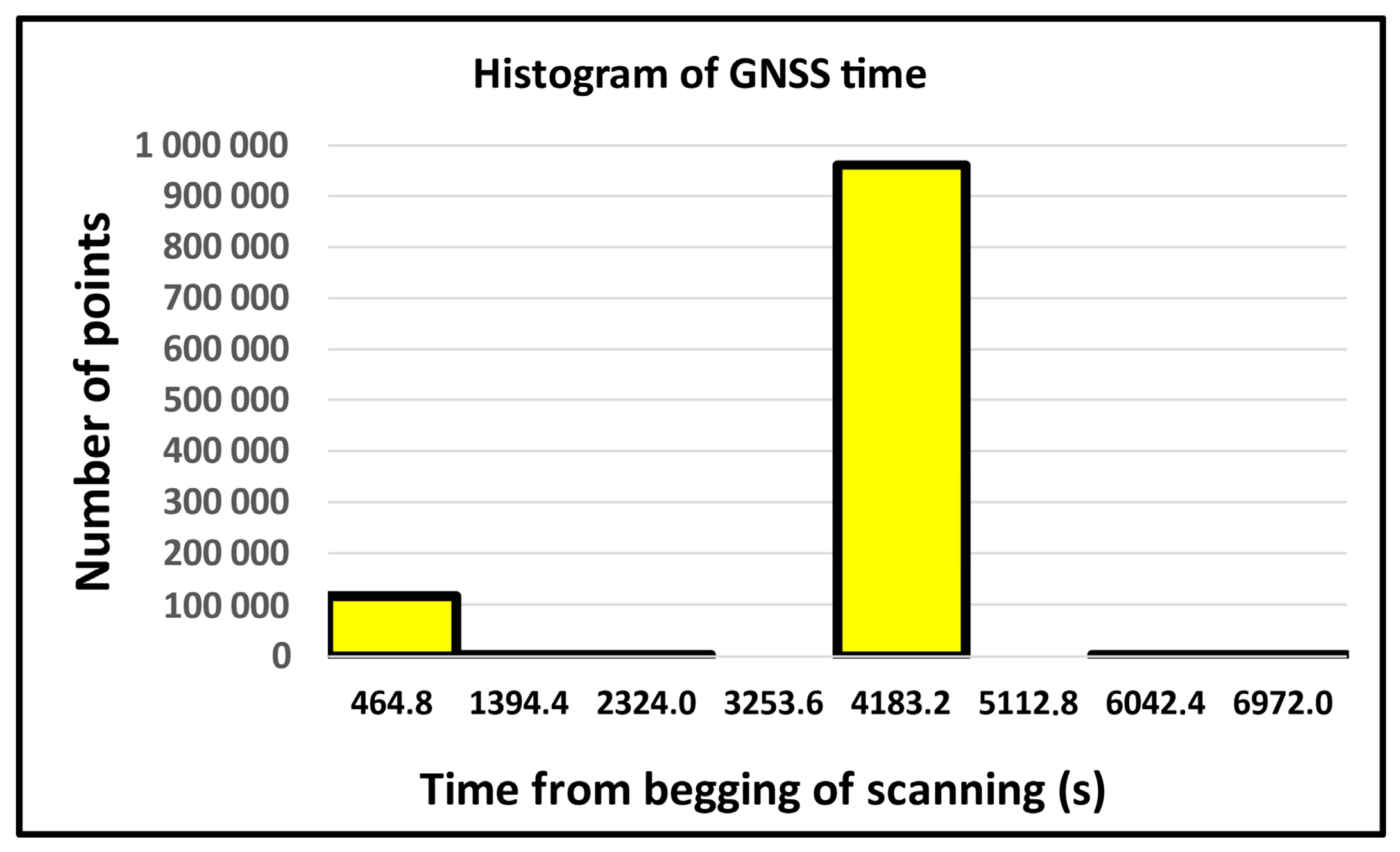
Although our proposal of point cloud clustering is primarily based on GNSS time, it also uses an analysis of the laser beam availability/occlusion during each of its periods to the part of the forest being scanned during it, caused by the configuration of the terrain and the distribution of stand tree trunks concerning the sensor trajectory. The point cloud for the sub-region is thus generated from the source point cloud in an integrated way based on both temporal and spatial constraints. Empty bins in the histogram of the point distribution over time for a spatially limited point cloud represent periods of occlusion (Figure 1—red areas). At the same time, empty bins in the histogram separate parts of the point cloud captured from different sensor positions. Following the above, we defined the concept of optimal clustering time in [88], which can be considered a measure of the MLS point cloud processability. The optimal clustering time is the longest possible time to cluster points from the source misaligned point cloud into sub-point clouds without copies of scanned objects using GNSS time-based point clustering. A longer clustering time reduces the subsequent processing time of the MLS data and thus increases the processability. However, the source point cloud may be misaligned because it does not allow clustering into usable sub-point clouds. The longer the clustering time, the less likely it is to occur.
This follow-up study aims to evaluate the influence of point cloud parameters, GNSS availability, and GNSS signal strength on the optimal bin width representing the processability of the point cloud. Understanding these relationships could provide deeper insight into improving MLS point cloud processability by choosing different mapping patterns and a better GNSS satellite constellation. All variables related to the GNSS data are derived from a histogram with a constant bin width (Figure 1). The histogram bins with less than four available satellites are considered no signal periods in this study. This number of satellites is usually considered the fundamental condition for differential GNSS measurement. The independent variables related to the GNSS signal availability consist of the number of outages and the total, mean, and maximum outage duration. Similarly, the GNSS signal strength is described using statistics of position dilution of precision (PDOP) values in each misaligned point cloud. Furthermore, we differentiate the GNSS signal statistics for the scanning periods (Figure 1—green) and the occlusion periods (Figure 1—red).

2. Materials and Methods

2.1. Study Sites

From the Forest Enterprise of the Technical University in Zvolen, with an area of 9724 ha, we choose an area of approximately 50 ha for mapping with the MMS. The mapped area consisted of forest stands with a high variability of tree species, canopy densities, and ages. It contained forest stands accessible via a network, skid trails located inside the forest stands, and a forest road. MLS data from two forest stands with a total area of 4.76 ha, which differ significantly in age, tree species composition, and canopy density, were processed in this study. Study sites were located in central Slovakia, within the municipality of Budča.
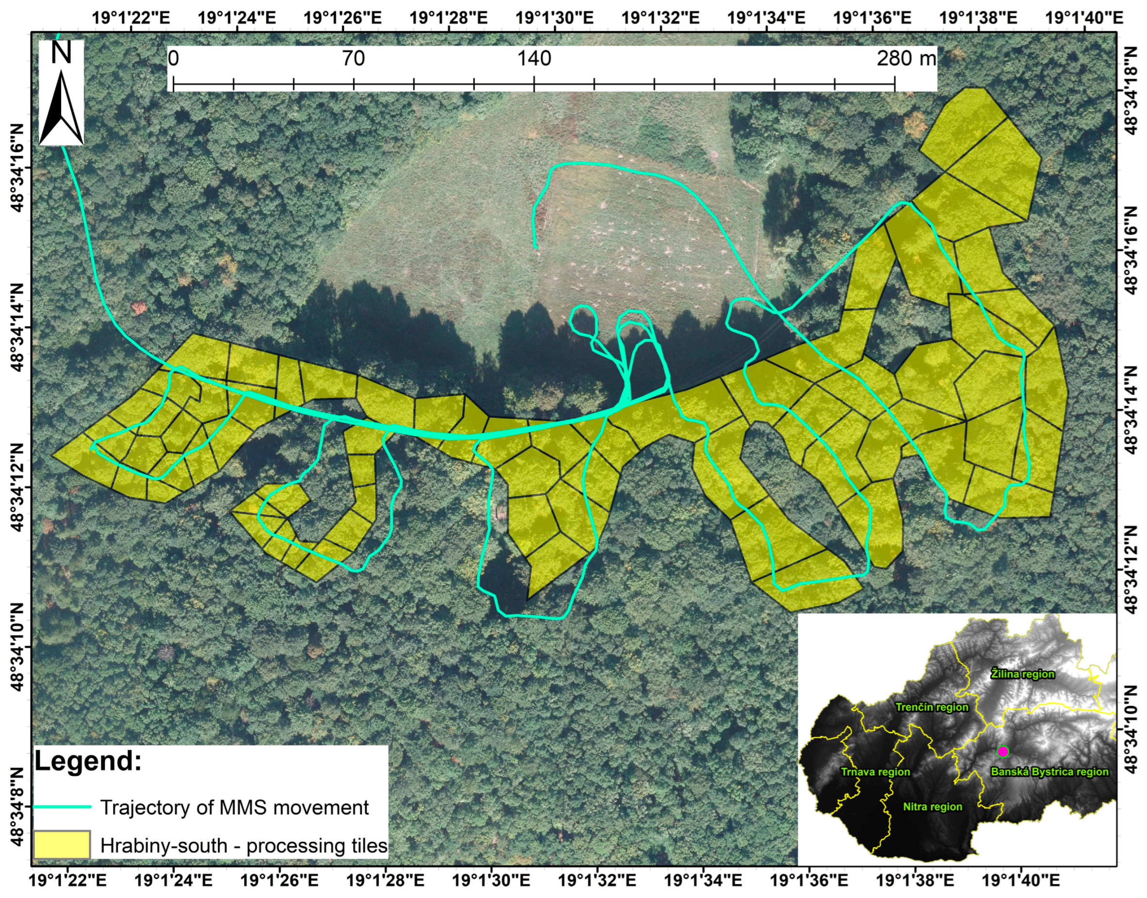
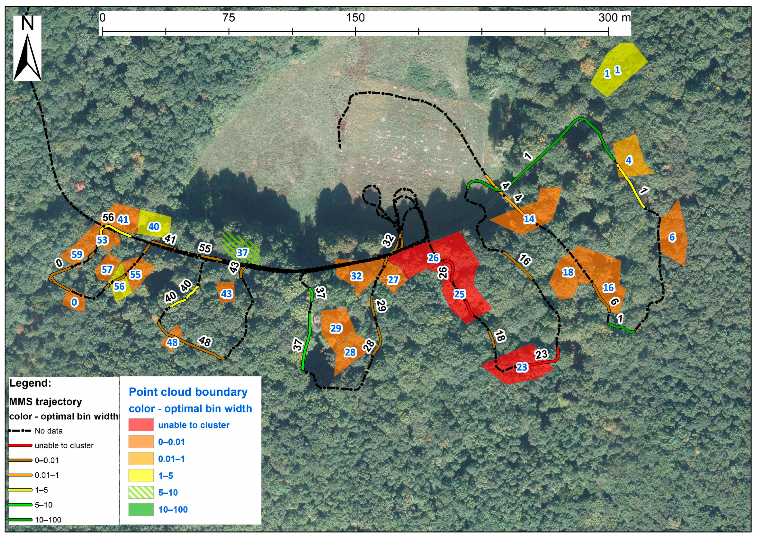
The first study site, Hrabiny-South (19.023114 dd E, 48.577458 dd N), with an area of 2.93 ha, was covered by a mixed beech, oak, and hornbeam forest (Figure 2). The forest stand consisted mainly of mature trees with a mean age of 110. It had a relative density of 0.7 and an absolute density of 181 trees/ha, with a mean diameter at breast height of 39.22 cm. At the first site, the study was conducted in an area around ten skid trails with a partially opened canopy. The studied forest neighbored an open area, allowing better GNSS signal strengths and static measurements before and after the survey.
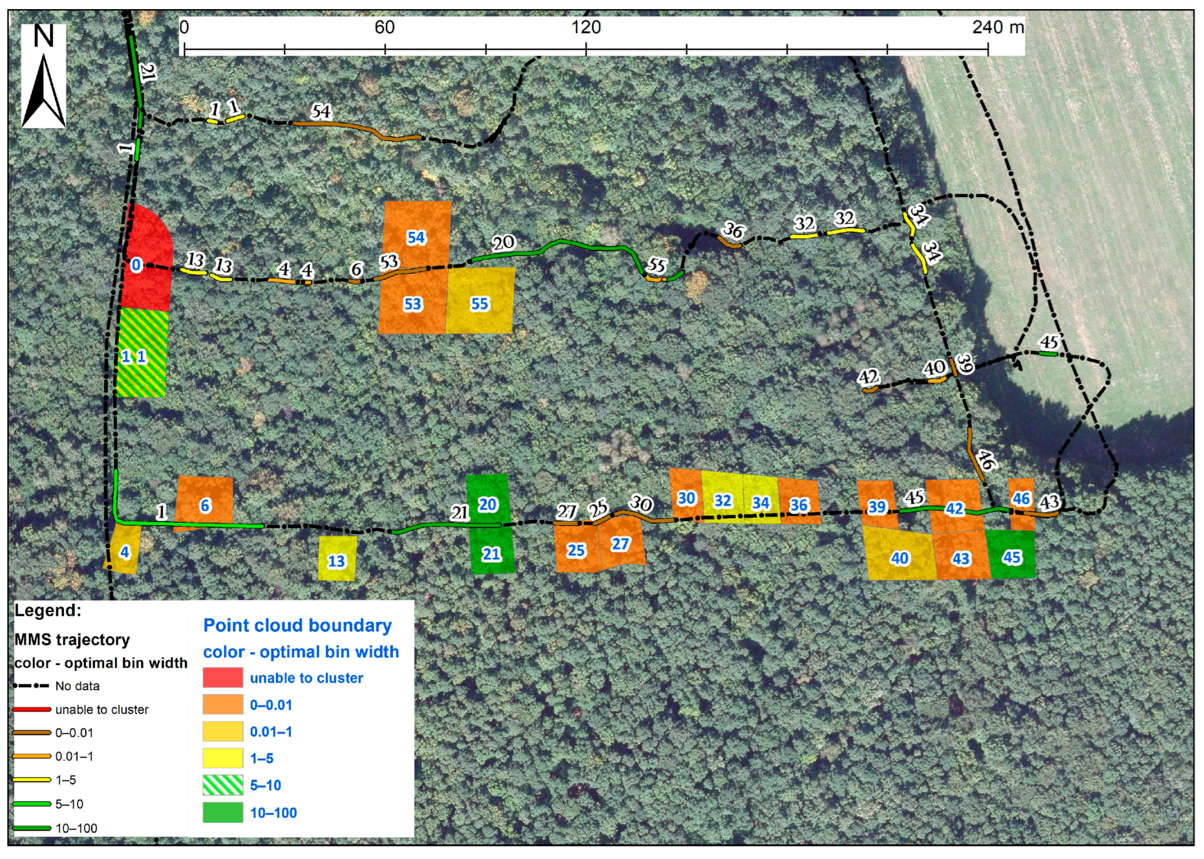
The second study site—Hrabiny-North (19.02429 dd E, 48.57001 dd N) of 1.83 ha—was covered by a mixture of hornbeam, Turkey oak, beech, Sessile oak and Silver birch trees. The trees‘ mean age was 55, and the mean diameter was 20.35 cm. In this site, the relative stem density was 0.7, and the absolute density was 838 trees/ha. The Hrabiny-North site was surveyed using a short section of the forest road and three parallel skid trails (Figure 3).

2.2. Mobile Laser Scanning Data

The MLS data were collected in July 2015 using the Riegl VMX-250 mobile mapping system (MMS) (Figure 4). The MMS was mounted on a Zetor Horal 7245 tractor (Zetor Tractors a. s., Brno, Czech Republic). The system was mounted on a platform installed on the tractor at approximately 1.8 m height. The MLS data were recorded at 600 kHz (2 scanners at 300 kHz frequency, intended for medium-range applications). The VQ-250 laser scanner measures objects with an accuracy of 10 mm and a precision of 5 mm. The system scans up to 200 lines/s at a 1.5–200 m distance from the scanner, using the 600 kHz frequency. This frequency allows 600,000 (2 × 300,000) measurements per second.
The MMS navigation system consisted of the Applanix GNSS-POS LV 510, IMU-31, odometer, and control unit. The Applanix GNSS-IMU navigation system, integrated into the RIEGL VMX-250, is only suitable for outages up to 1 min/1 km [112,113]. The GNSS-IMU of the system is specified by the standard deviations of absolute positions ranging from 2 to 5 cm and the standard deviation of relative positions of 1 cm for measurements without an outage.
The tractor moved throughout the study sites at walking speed (approximately 5 km/h). The data acquisition started at an open area, where GNSS statically measured the position for 10 min. MMS then collected most of the data from skid trails within the forest with a partially opened canopy.
The trajectory was calculated from differential GNSS data processed by its integrated Applanix’s POSPac navigation unit to reference the MLS data. The GNSS data were acquired from the reference station installed on the roof of the main building of the Technical University in Zvolen (6.9 km from the Hrabiny-South study site and 7 km from the Hrabiny-North study site). The calculated trajectory was imported into RiPROCESS (Riegl). In the RiPROCESS 1.9 software environment, the MLS point cloud was generated and geo-referenced.

2.3. Navigation System Data

The GNSS data were collected using an external inertial navigation system (INS) NovAtel® ProPak6 (Figure 4). The INS integrates the ProPak6 GNSS receiver with the IMU-KVH1750. The INS was mounted on the skidder cabin next to the MMS. The GNSS antenna of the INS was located in front of the MMS antenna with an approximately 1.5 m shift. The positional accuracy of the ProPak6 is specified as the root mean square error of 0.4 m for the differential GNSS (dGNSS)-based positioning. NovAtel CORRECT™ algorithm can then further improve the accuracy by up to 1 cm.
In this study, we used the data from the GNSS/INS navigation system to approximate the point cloud’s georeferencing. The INS data were imported into Inertial Explorer®. The data were processed in both forward and reverse directions using the tightly coupled solution, dGNSS-based processing. Data on PDOP and the number of satellites were exported into a text file with 0.2 s timestamps.

2.4. Mobile Laser Scanning Data Processing

Geo-referenced MLS point clouds were merged into two overall point clouds—one for each of the two system scanners. From these two merged point clouds, only points coming from the area of the study sites were extracted based on the polygons of the study site definition (two point clouds for each study site). These point clouds were then divided into smaller tiles containing approximately the same number of trees on the point cloud cross-section (Figure 2 and Figure 3). This tiling design was applied to generate point clouds with a similar quantity of points. Additionally, the part of point clouds from the Hrabiny-North point clouds was tiled regularly. Each point cloud from the first study site was divided into 65 tiles for each scanner (130 tiles total). Each point cloud from the second study site was divided into 68 tiles for each scanner (136 tiles total). The point cloud tiling is supposed to decrease the time of the following processing and ensure the occurrence of gaps with no points on the histogram of the GNSS time.

2.5. GNSS Time-Based Point Clustering

We have previously verified GNSS time-based point clustering in [88] to eliminate vertical shifts in point clouds from forest conditions and examine the relationship between the processability of MLS data and the data on GNSS signal strength and availability, as well as point cloud parameters (Figure 5). Bienert et al. (2018) in [113] proceeded in a similar way in the MLS data preprocessing.
In this study, following the steps described so far, we further clustered the merged points of the point cloud until only two copies of the trunks or ground were visible in the generated point clouds. Additional clustering was done separately for the point cloud with the two copies of the scanned objects. Two copies were isolated using GNSS time-based point clustering with the maximum bin width, which allowed the clustering of the two copies into two partial point clouds with no copies. The maximum bin width was recorded as optimal for further analyses. This process was performed manually and iteratively, with a visual inspection of successive results (Figure 6).
Multi-level clustering allows for better isolation of only the period during which the accuracy deteriorated, and two scans of the plot resulted in two misaligned copies of the same plot. Otherwise, the GNSS data and the more giant point cloud parameters with more than two copies would be analyzed regarding the optimal bin width used for isolation of only the two copies of the plot scanned in the shortest time.

2.6. GNSS Data Processing

Data on position dilution of precision (PDOP) and the number of satellites were also processed based on the histogram of GNSS time for the point cloud with two copies of scanned objects. The histogram with a bin width of 0.1 s was created for each point cloud before the clustering. The GNSS data were extracted for each bin. If no data within the range of the bin ± 0.1 s were found, the bin with a GNSS outage was registered. The total outage duration was recorded if a sequence of outage bins was detected. For both PDOP values and outages, all the statistics were calculated for the scanning and occlusion periods. The bins with more than 0 points defined the scanning periods, and the occlusion periods consisted of empty bins. We considered the maximum outage duration the most extended continuous duration of the GNSS outage. The median outage duration was calculated as the average of all outage durations.

2.7. Statistical Analyses

2.7.1. Derivation of the Point Cloud Parameters

This study analyzed the influence of ten parameters of the point cloud with no copies of scanned objects on the optimal bin width. The influences of the point cloud’s time range, scanning durations, and occlusion durations were analyzed. Maximum and total durations were calculated from the scanning mean and occlusions. Basic parameters of the point cloud, such as the number of points (N) and point cloud spatial density, were derived from the point cloud data. Additionally, the temporal density of a point cloud was calculated. The spatial density of a point cloud was calculated by dividing the number of points by the area of the tile (N/a). The temporal density was calculated by dividing the point count by the point cloud’s time range (N/tT).

2.7.2. Stand-to-Stand Comparison of the Processability and GNSS Signal Availability

Due to significant differences in stem and canopy densities between the analyzed study sites, optimal bin widths, point cloud parameters, GNSS signal strengths, and outages were compared between the study sites. The significance of the differences between the means was tested using the independent-samples t-test. Overall, 14 variables were tested. Calculated t-values were compared to critical t-values at a probability level of 0.05. Similarly, Levene’s test tested the significance of differences between the variances. The f-values calculated using Levene’s test were compared to a critical value from the F-distribution at a probability level 0.05 [114,115].

2.7.3. Correlation and Regression Analysis

Correlation and regression analysis included 27 relationships between the optimal bin width and an independent variable. Nine independent variables were derived from the point cloud data. The variables include the number of points, point distribution in space and time, basic statistics of the scanning durations, and occlusion (total, mean, max). The variables related to the GNSS outage and signal strength were analyzed separately for the whole point cloud’s time range, the scanning bins (with points), and the occlusion bins (empty bins). A total of 12 variables were statistics of the GNSS outage (number, total duration, maximum duration, mean duration). Six independent variables were PDOP statistics (sum, max, and mean).
After the initial observations, we found dozens of point clouds scanned entirely during the GNSS outage and with very homogenous PDOP values. For this reason, the power of the linear relationship between the point cloud time range and the variables related to the GNSS outage and signal strength were examined before further analyses. Furthermore, the relationship between the GNSS outages from the scanning and the occlusion periods and the total duration of scanning and total duration of occlusions were analyzed, respectively. Similarly, the relationship between the PDOP statistics from the occlusion and scanning periods and the corresponding total durations of the scanning and occlusions were also analyzed. If the variable correlated with the entire duration of its corresponding time range with a coefficient of determination higher than 0.75, it was excluded from the analysis.
The original values of point cloud parameters transformed by a natural logarithm were analyzed according to the optimal bin width. The transformation decreased the extreme differences between the optimal bin widths and the number of points and related variables [116,117]. In addition to the natural logarithm transformation of parameters related to the number of points (point cloud spatial and temporal density), the values of scanning duration statistics were also transformed. In the case of the scanning duration values, the transformation was used to reduce the influence of the outliers presented in the paired data on optimal bin width and the scanning duration statistics.
The best-fitting curve was chosen from the nine regression models to describe the twenty-seven relationships. The nine models were defined as follows:
the linear model was defined as:
t opt = a + ( b   ×   I ) ;
the logarithmic model was defined as:
t opt = a + ( b   ×   ln ( I ) ) ;
the inverse model was defined as:
t opt = a + ( b / I ) ;
the power model was defined as:
t opt = a   ×   I b ;
the compound model was defined as:
t opt = a   ×   b I ;
the S-curve model was defined as:
t opt =   e ( a + ( b I ) ) ;
the logistic model was defined as:
t opt = 1 1 u + ( a ×   b I ) ,
where u is an upper boundary value;
the growth model was defined as:
t opt =   e a + ( b × I ) ;
the exponential model was defined as:
t opt = a   ×   e b × I ;
where t opt is the optimal bin width, I is an independent variable, and a and b are model parameters. A model with the highest coefficient of determination was then assigned to the relationship. If multiple models had the same power, the simplest model was assigned to the relationship.
The significance of the best-fitting model’s parameters was tested in comparison to an intercept-only model. The significance was tested using the F-test, and the F-values were calculated as follows:
F = (SSRM-μ/p)/(SSRM-O/N-p-1);
where SSRM-μ is the sum of the squared differences between the value expected based on the best-fitted regression model and the mean of the observed optimal bin widths, SSRM-O is the sum of the squared differences between the expected value and the observed value, N is the number of observations, and p is the number of parameters (which was equal to one in all cases).
The F-value was compared to a critical value to reveal if the model fits the data more than the intercept-only model. The critical value was calculated at a probability level of 0.05. A relationship was considered significant if its F-value was higher than the critical value and the model function agreed with the previous research [118]. The consensus with the previously published study was considered based on the best-fitting model’s sign of shape. If the processability was increasing with the increasing PDOP or outage statistic, the significance of the relationship was rejected despite the sufficient F-value.

3. Results

The influence of the point cloud parameters, GNSS signal availability, and GNSS signal strength on the processability of the MLS point cloud was evaluated for a set of point clouds without outliers. The original sample size of 268 point clouds was reduced to 265 point clouds that contained any points (Table 1). From the 265 misaligned point clouds, 255 were successfully clustered into point clouds with no copies of the scanned objects in the first stage of clustering. A total of 10 point clouds were not processable even after setting the bin width to 0.001 s, which was the precision of the data on the GNSS time. The point clouds with only misaligned copies of the scanned objects were clustered using a bin width 0.1 s higher than the optimal bin width (0.001 if the optimal bin width was less than 0.1). From the 255 point clouds clustered in the first stage of clustering, 283 different point clouds with two copies of the scanned objects were generated. In the second stage of clustering, the point clouds with two copies of the scanned objects into two point clouds with no copies. Overall, 275 point clouds were analyzed. Eight point clouds were excluded from the evaluation due to their high optimal bin width.
The point losses from clustering were analyzed by setting the minimum number of points for the point generation to 5000. This limitation led to a certain amount of point losses. The mean point loss with this limitation was 42.3%. Overall, 47 point clouds lost no points after the clustering, and 125 point clouds lost less than 25% of points. A total of 63 point clouds lost all their points in the clustering process, and 79 point clouds lost more than 75% of their points. Of the 63 point clouds with 100% point losses, in 9 cases, the point losses were caused by a low number of points (ranging from 3260 to 7042).
GNSS signal conditions in this study were insufficient for more extended mapping. The GNSS outages lasted up to 87 s, with a mean GNSS outage duration of 3.536 s. In several cases, the GNSS outages lasted for the whole duration of the point cloud scanning. The outages were frequent, with a mean number of outages per point cloud of 59. The mean time range for a point cloud was 47.028 s. The scanning system producer specified that the maximum outage (1 min/1 km) was exceeded during the scanning of the five point clouds. All these point clouds, however, were clustered using a high optimal bin width value (ranging from 19.5 s to 80.7 s). Overall, the PDOP value ranged from 0.79 to 655.34, with a mean of 18.908 in the Hrabiny-South (mature stand) site and 16.994 in the Hrabiny-North site (young stand).

3.1. Differences in Processability between the Young and the Mature Stand

The differences in processability, point cloud parameters, and GNSS signal availability between the forest stands were evaluated using means, standard deviations, and the t-value of the fifteen variables (Table 2). The t-test revealed only two significant differences in the means of the variables. The total duration of occlusions was significantly higher in the Hrabiny-North study site, with a higher stem density. The difference suggests that the denser the forest is, the longer the occlusions last. On the other hand, the difference in the mean scanning durations for the two study sites was not significant. From the parameters related to the GNSS signal, only the difference between the means of the number of outages was significant. Even though the canopy was more open in the Hrabiny-South study site, the mean PDOP and mean outage for this site were similar to the younger forest on the Hrabiny-North site.
Variances of the seven variables presented in Table 2 differed significantly between forest stands. Besides the significant differences in mean values, the total duration of occlusions and the number of outage variances were also considerably different. Additionally, threshold, total durations of scanning, maximum duration of occlusion, maximum outage durations, and mean outage duration variances differed significantly. The comparison showed higher variability of the processability for the plots from the denser forest. On the other hand, the maximum outage durations are also more variable in the thicker forest stand. The comparison indicates that the conditions for the GNSS measurements were unfavorable in both study sites, and the processability was influenced solely by the occlusion time.

3.2. Influence of Point Cloud Parameters on the Processability of the MLS Point Cloud Collected under a Forest Canopy

The influence was evaluated for the 275 point clouds from the two study sites without outliers (Table 1). The point clouds’ parameters related to the point distribution were analyzed as the natural logarithms of the original data (Table 3). Transformation of the data decreased the influence of extreme differences between the parameters and the optimal bin widths. While the optimal bin widths varied between 0.001 and 92.1, the number of points varied between 3260 and 17,021,884. Consequently, the high number of points influenced the values of the derived densities. All these three parameters correlated significantly with the optimal bin width, with the highest R2 of 0.471 for the relationship between the optimal bin width and the temporal point density. The correlation shows the strong influence of the point distribution in time on the processability of the MLS data collected under a forest canopy.
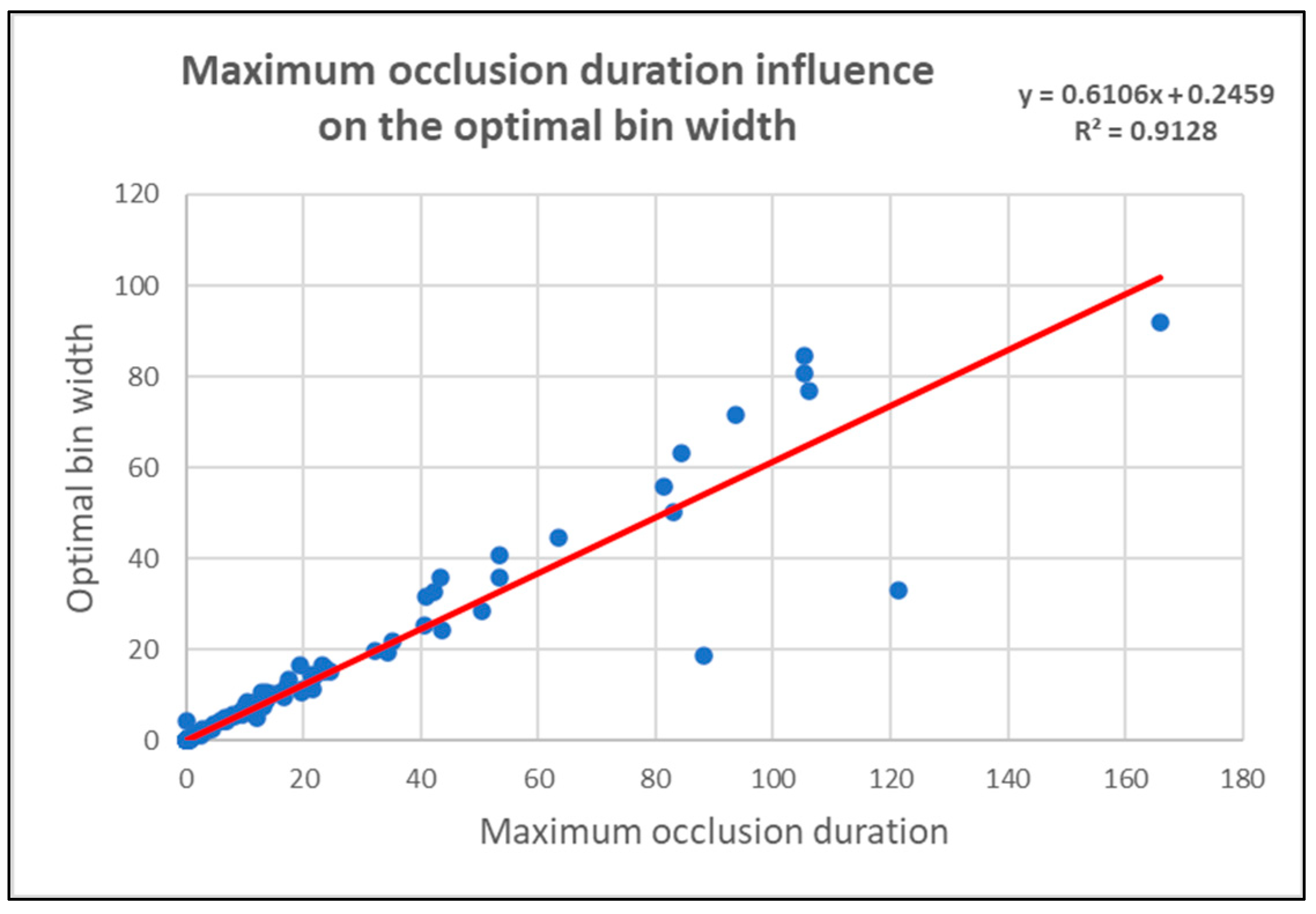
Our research demonstrates a precise correlation between time-related parameters of the point clouds and the optimal bin width, with powers ranging from 0.038 to 0.913 (Table 4). The time range of the point cloud is accurately related to its optimal bin width, with an R2 of 0.603. A detailed breakdown of the time range reveals that the total duration of the occlusions holds a strong influence over the optimal width, with an R2 of 0.761, significantly higher than the influence of the total scanning duration (R2 of 0.066). Furthermore, we found a robust relationship between the maximum occlusion duration and the optimal bin width (R2 = 0.913). This linear relationship suggests that the occlusions of the laser beam with the longest duration have the most significant impact on the processability (Figure 7).
From scanning duration statistics, it was found that the mean scanning duration had the highest correlation with the optimal bin width (R2 = 0.485). The optimal bin width was also found to be closely related to the data on the mean scanning duration transformed by a natural logarithm. Interestingly, some of the paired data on scanning durations and the optimal bin width were outliers, as evidenced in the lower part of Figure 8. These outliers had a significant impact on the regression model’s fitting, leading to the conclusion that the transformed data on the scanning duration statistics correlated more with the optimal bin widths. This finding has practical implications, suggesting that very short scanning durations could potentially improve the processability of the MLS point cloud from within the forest.
The relationship between the mean scanning duration and the optimal bin width was best described by the linear model as follows:
ln ( t opt ) = 1.939   ×   ln ( t s ) + 2.043 ;
where t opt is the optimal bin width, and t s is the scanning duration. This model shows that for 48.5% of the point clouds from this study, the mean scanning duration had to be around 1.25 s to be clustered into the correct point clouds using a bin width of 5 s.

3.3. Influence of GNSS Signal Availability on the Processability of the MLS Point Cloud Collected under a Forest Canopy

In this study, the influence of GNSS outage on processability is unclear. Some correlations were found between the GNSS outage statistics and the optimal bin width (Table 5). The most decisive influence on the optimal bin width was found for the total duration of GNSS outages during the occlusions. However, this variable strongly correlates with the total duration of occlusions, and all tested models suggest that more extended GNSS outage durations increase processability. The total GNSS outage duration and the point cloud time range strongly correlated with R2 of 0.859. Similar results were found for the total duration of GNSS outages and the total duration of GNSS outages during the scanning. The correlation analyses showed that a solid linear influence of the durations of the different time ranges on the totals of the GNSS outage durations from these time ranges can be expected. The total GNSS outage duration from the scanning periods correlated with the total scanning duration with an R2 of 0.762. The total GNSS outage from the periods of occlusion correlated with the total occlusion duration with an R2 of 0.933. For this reason, the statistics for the total duration of outages were excluded entirely from the study.
The influence of the number of outages for all time ranges indicated that a higher number should improve processability. Moreover, the extended maximum GNSS outages for the whole time range and occlusion periods improve processability. All these relationships were, therefore, considered insignificant. The only significant relationship was found to be between the optimal bin width and the mean duration of the GNSS outage from the scanning periods. However, the relationship is fragile (Table 5).
No significant correlation between the PDOP statistics and the optimal bin width was found in this study. Similar to the influence of outage on processability, analyses of the PDOP statistics from the occlusion periods indicate an increase in the processability with an increase in the PDOP statistic (mean, max, and total). The PDOP statistics from the scanning periods did not significantly influence the optimal bin width in this study.

4. Discussion

This study fully confirms that there are better environments for mapping using GNSS-positioned MLS systems than the forest. Frequent GNSS outages with durations up to 87 s, in combination with the high PDOP values, resulted in misaligned point clouds. Even after the spatial tiling of the point cloud, ten point clouds were not processable at all. Despite these conditions, 96.5% of the data were clustered into point clouds with no copies of the scanned objects. Clustered point clouds were sometimes small and based on the minimum number of points stated for the generated point cloud; they could be too small for subsequent processing for tree measurements. Depending on the study’s goal, we can consider the success rate of the presented method to be between 16.5% (0% point loss with a 5000 minimum number of points requirement) and 96.5% (misaligned point clouds clustered into sets of points with no copies of scanned objects).
The potential for further research emerges from two essential findings from the presented study, which contradict the traditional understanding of the application of mobile (vehicle-mounted) MLS systems located by GNSS/IMU inside the forest environment. First, the denser canopy will probably not cause more issues when the GNSS time-based point clustering is used to process the MLS data. The differential GNSS measurements inside the forest are challenging and will not be accurate even in the mature forest stands with canopy openings above the skid trails. Nevertheless, with the help of standard MLS devices working with high scanning frequencies, it is possible to achieve the relative accuracy of the partial point clouds from the forest, which is sufficient for basic forestry applications such as tree identification or tree parameter estimation.
Second, the occlusion of the sub-plot scanning by tree trunks and terrain outside it will improve the processability of the MLS data. Therefore, the higher stem density of a forest stand can be considered an advantage (and not a negative factor) in mapping as it increases the duration of the occlusions for a point cloud after it is spatially tiled. Moreover, the occlusion could be artificially increased by pausing a plot’s scanning for a short time during data gathering. The pausing will result in gaps in a point cloud’s histogram over the GNSS time. The higher speed of the MLS system carrier can also ensure the shorter scanning duration of the same plot. Finally, scanning with a higher scan frequency can avoid more point losses. The higher scan frequency increases the number of points scanned during a specific period; therefore, the overlap of the clustered point clouds will be more significant.
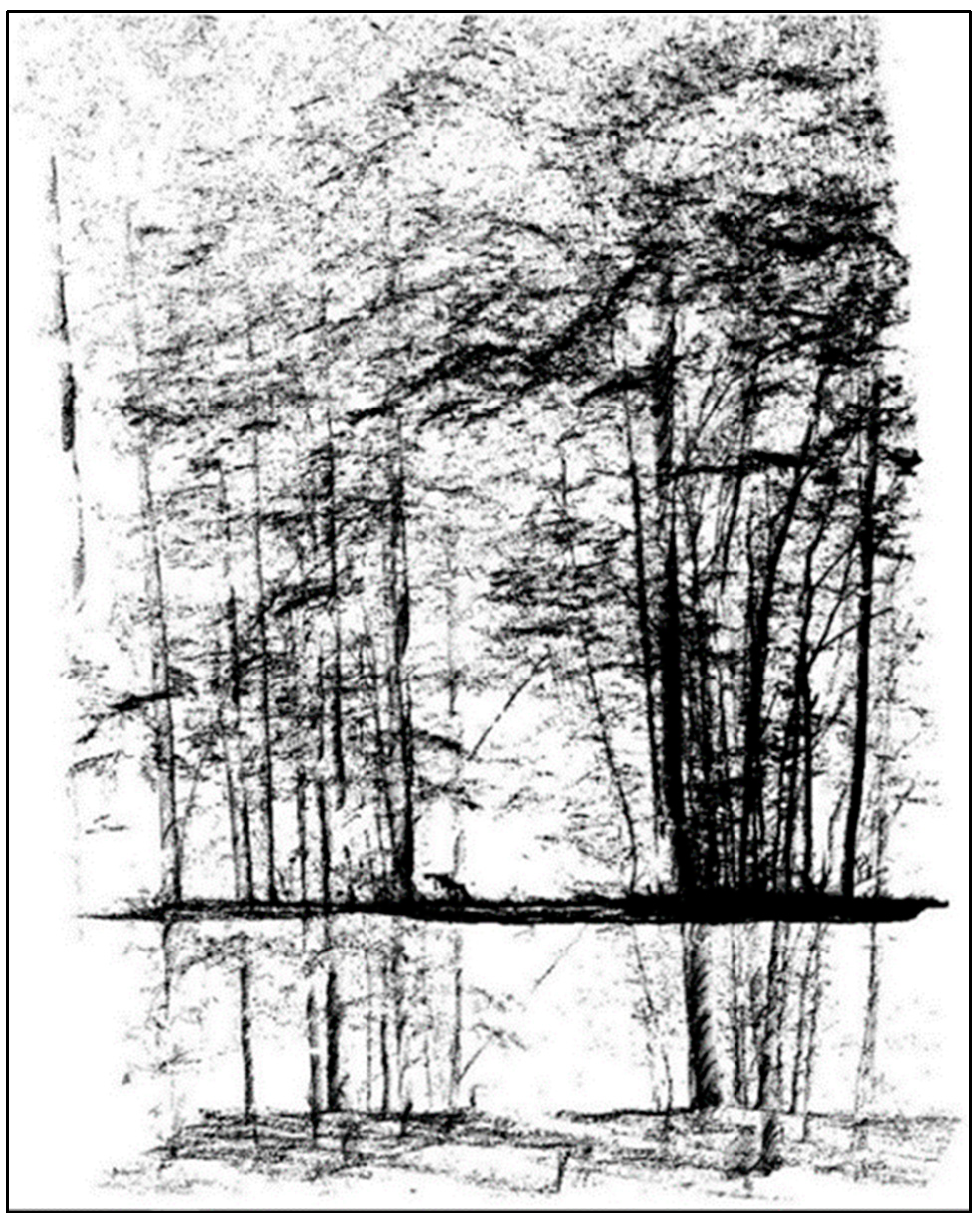
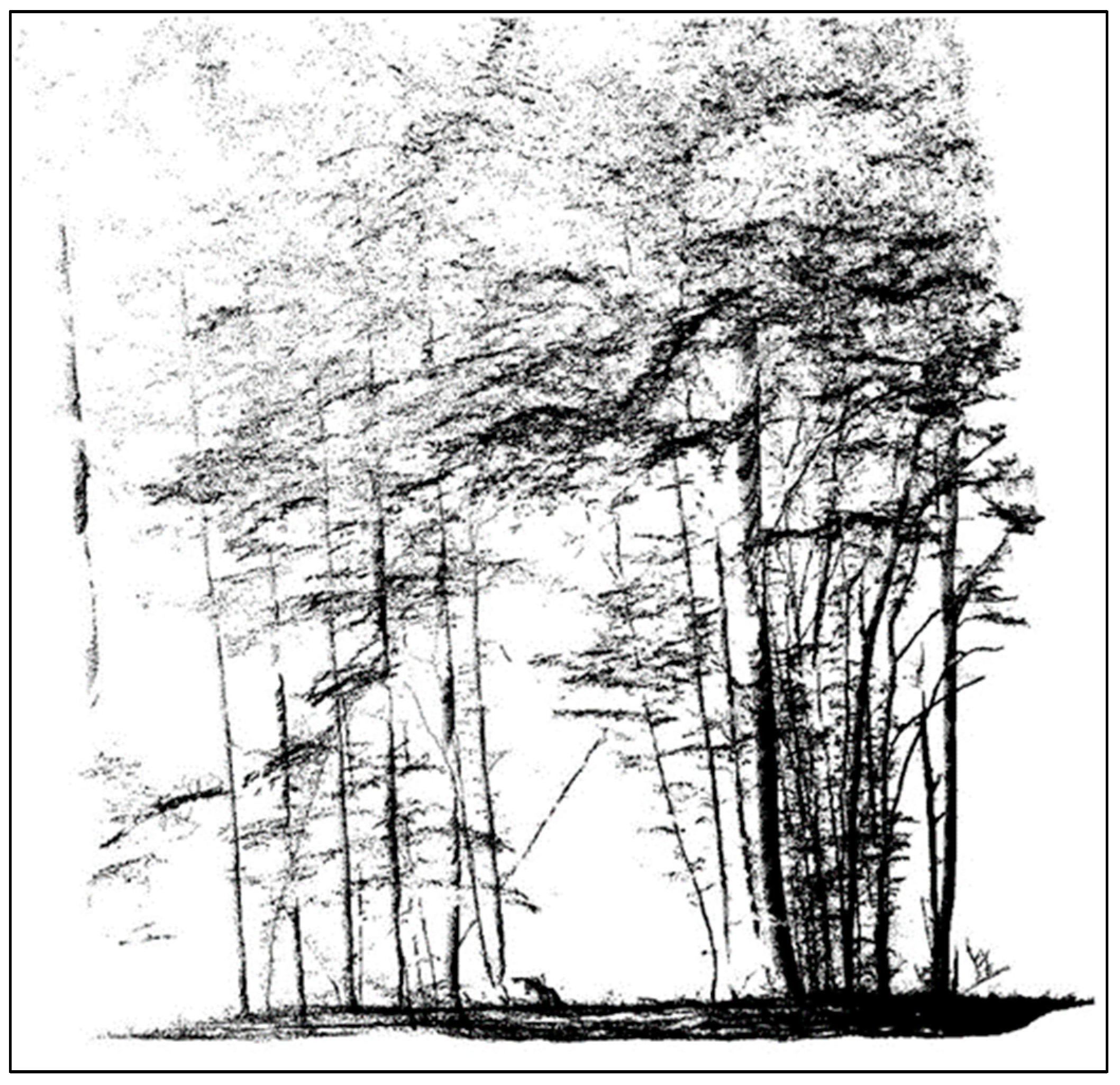
To better understand the relationship between the mapping pattern and the optimal clustering time, we also present a visual representation of some point cloud scannings. The representation shows both the scannings and the occlusions of the laser scanning in the trajectory of the MMS‘s movement (Figure 9 and Figure 10). The smoothed trajectory does not accurately represent the actual situation, even though the best possible method was used to calculate forward and backward directions using a deeply-integrated dGNSS processing solution (see also Methodology, navigation data). The reason is the low quality of the GNSS signal, including its complete outages in certain parts of the route, leading to errors in its localization points calculation. However, it can provide a deeper insight into the relationship between the mapping pattern and processability. The point clouds were chosen to maximize the variability of optimal bin widths and the coverage of the trajectories in the figure.
The results of the presented study can be assessed and compared with the research results published so far in two ways—in a narrower and broader context. In a narrower sense, the presented study brings several new (as yet unpublished) approaches and results. According to our knowledge, these are (i) time-based point clustering for preprocessing unaligned point clouds, (ii) defining the optimal time width concept, and (iii) evaluating the impact of GNSS outage durations, signal strength statistics, and the point cloud parameters on the optimal bin width. Due to its simplicity, temporal clustering is easily applicable even to large volumes of data typical of MLS. Empty bins in the histogram of the points distribution over time represent periods of occlusion and separate parts of the point cloud captured from different sensor positions. The optimal clustering time is the longest possible time to cluster points from the source misaligned point cloud into sub-point clouds without copies of scanned objects using GNSS time-based point clustering. Verifying the mentioned statistical dependencies required to create isolated copies of partial point clouds in advance based on GNSS time-based clustering in a manual, interactive, and iterative way with visual inspection on a large sample of 275 point clouds. The optimal bin width was strongly related to the point distribution in time, especially by the duration of the scanned plot’s occlusion.
In a broader context, it is necessary to state that the potential benefit of vehicle-mounted high-frequency MLS in forestry is so great that the problems with their localization using GNSS/IMU are understood more as a challenge than an obstacle [50,119,120,121]. Although our experiments were performed in a forest environment, their results can be applicable for mapping by MLS systems in any environment with poor GNSS signal quality and more prolonged and frequent GNSS outages—urban canyons; transportation infrastructure mapping in challenging conditions, including bridges and tunnels; and highly-structured urban and agricultural landscapes.
As shown in the Introduction, the inconsistency in positional accuracy of the point cloud created using a mobile (vehicle-mounted) MMS can be improved by: (i) increasing the GNSS and INS integration performance, (ii) SLAM algorithm implementation in the positioning of equipment, (iii) the use of ground control points (GCP) for final point cloud re-adjusting (3D translations) or sensor trajectory correcting by adding external position updates, and, finally, (iv) the use of specific procedures for route and point cloud data processing as we proposed in the submitted studies. We used current/up-to-date technology for our experiments. Even in such circumstances, our study results show that a promising approach focusing on the point cloud parameters, the evaluation of measurement conditions, analysis, and the specific assessment of the standard MLS data gathered with commercial MMS in challenging situations can improve its processability and utilization. The parameters and efficiency of the technology are in rapid positive development (see also in the following paragraphs). Any positive development in source and related areas could bring the next improvements, including efficiency increase of the GNSS/INS integration and SLAM-based equipment efficiency, as well as the implementation of innovative mapping methods.
Advanced methods of GNSS/INS integration might be constructive and beneficial. Most prospective integration approaches by [65] are considered loosely and tightly coupled systems based on the extended Kalman filter and its modifications [122,123,124]. Using neural networks to simulate GNSS signals not in the field of view provides relatively good accuracy when used in integrated GNSS/INS systems [125,126,127,128]. However, their implementation’s time and computational costs can significantly exceed similar costs when using the standard extended Kalman filter. A more reliable approach to solving the problem of temporary unavailability of GNSS measurements is using GNSS receivers that work with more navigation systems [65,129,130]. Development and testing of the new integration algorithms offer the following perspective for GNSS outage solutions [66,131,132,133], including the SLAM-based integration scheme [134,135,136]. Additional onboard sensors that can be used for navigation are required to improve the performance of navigation systems, which will allow the system to sustain prolonged GNSS outages [137,138,139,140], including LiDAR [120,141,142].
With the vigorous driving of sensor technology and 3D reconstruction algorithms, many attempts have been made to propose novel systems and algorithms combined with different sensors to solve the SLAM problem [78,143,144]. Ding et al. (2022) [80], focus on the recent developments and applications of SLAM, particularly in complex and unstructured agricultural environments, to various aspects of autonomous navigation, 3D mapping, field monitoring, and intelligent spraying [120,145,146,147]. Aldibaja et al. (2022) [148] published a unique Graph SLAM framework to combine maps based on node strategy that has verified the proposed framework’s robustness, accuracy, and outperformance against an accurate GNSS/INS-RTK system while improving the global position accuracy. SLAM also has limitations such as noisy point clouds, the need for reference objects, or low scanning frequencies if the commonly available devices are used. Mobile laser scanners and SLAM technology applications in forestry have recently been the subject of detailed focus [149,150].
The traditional/classical approach uses ground control points for re-adjusting (georeferencing) or alignment of the point cloud scanned during the sensor outage periods [151,152,153]. This solution was used by Boavida and Oliveira (2012) in [112] during the tunnel mapping with the Riegl VMX-250. Tunnel profiles deviated only up to 3 cm from the profiles measured by the total station. A high number of control points is required to reach this level of accuracy. Another reference was used by Rönnholm et al. (2016) in [21]. The authors used laser scanning data from unmanned aerial vehicles (UAV) as a reference in this study. The patches of points collected from the ground from the MLS point cloud were then aligned to the reference point cloud scanned from the UAV. Kalvoda et al. (2021) [154] focused on the influence of ground control point numbers and their configuration on mobile laser scanning accuracy. The accuracy differences between geometry-based and trajectory-based configurations were not statistically significant. The accuracy increased significantly with the increase in the number of GCPs to six.
Providing the position information of the sensor (vehicular trajectory) is often used as crucial auxiliary information to process large amounts of MLS data [155], to establish a local coordinate system, and to convert the 3D point cloud into two-dimensional (2D) grid maps [54]. Trajectory data have provided the basis for extracting road sections [156,157] and cross-sections of tunnels [158], separating the target from the background, and noise removal. It is also a typical pre-processing step to segment the MLS data along the vehicle’s trajectory according to a predetermined distance [159,160] or constant interval [161]. The GNSS signal is relatively available in the mentioned applications, and only occasional or short-term outages are assumed. Zhong et al. (2020) [162] proposed a specific method to recover missing sensor trajectory data, which they consider a challenging task due to the degraded positioning accuracy at urban canyons and city centers, the large amount of data collected, the complexity of the road environment, and occlusion situations. The MLS point cloud accuracy evaluation remains complex, even if sensor trajectory points from the forest conditions are corrected using the trajectory’s ground control points [73].
Instead of trying to increase the accuracy of the localization of the sensor trajectory points, which is (in conditions under the forest canopy cover) principally outside the required frames of precision, nor to use GCP marking, the proposed procedure of Čerňava et al. (2019) in [88], and the content of this study, especially, enables the identification of spatially and temporally homogeneous patches (parts of the point cloud) gathered from a single sensor location regardless of what it exactly was. That result is conditioned by the high scanning frequency, which produces a sufficient number of points concerning the relatively low speed of sensor movement. The analyses in this study proved that the possibility of creating such internally homogeneous parts of the point cloud has no relationship with the characteristics of the point cloud or the quality and GNSS signal outage frequencies or duration, respectively; these circumstances do not affect it. The close relationship to occlusion confirms the conditionality of identifying homogeneous parts of the cloud to the occurrence of empty histogram classes.
The correctness of the presented concept would be supported by the results of several successfully published laser point cloud preprocessing approaches. More extensive area processing is expected to collect multiple point clouds appropriately and integrate them using registration into a standard mapping coordinate system [92]. According to [163], registration methods are divided into rigid [164] and nonrigid if the registration object is deformed. The former is typical for moving scenes or objects that change shape over time. According to the type of theoretical solutions to point cloud registration, five categories exist, led by iterative closest point (ICP)-based methods [77,90,165]. For ICP-based algorithms, the generation of a good initial position for its application is vital. Pan et al. (2018) [166] and Huang et al. (2017) [167] proposed a global transformation strategy as an initial position for the point cloud and local transformation that can guarantee the result of registration. These two phases are called coarse-to-fine strategies and are commonly applied for registering multiple point clouds or their parts [77,168,169].

5. Conclusions

This study analyzed 275 MLS point clouds from two study sites. We conclude that the GNSS signal strength and availability inside the forest need to be improved for accurate differential GNSS measurements. The analyzed point clouds showed a different level of misalignment. For most misalignment point clouds (96.5%), it was possible to cluster into point clouds with no copies of the scanned objects by exploiting the empty bins in the histogram of GNSS time. This study indicates that the maximum bin width used to cluster the misaligned point cloud points into point clouds with no copies of the scanned objects describes the point cloud’s misalignment level and its processability for the next application. The clustering was done in two levels, and the maximum bin width used for clustering the points from the point cloud with two copies of the scanned object into two point clouds with no copies was further analyzed as the optimal bin width. A denser canopy will probably not cause more issues when the GNSS time-based point clustering is used to preprocess the MLS (mobile laser scanning) data. The occlusion of the sub-plot scanning by tree trunks and terrain outside it will improve the processability of the MLS data. Therefore, the higher stem density of a forest stand is an advantage in mapping as it increases the duration of the occlusions for a point cloud after it is spatially tiled.
The relationship between the GNSS outage duration, PDOP statistics, and the optimal bin width (a measure of the size of the bins used to group data in a histogram) was analyzed in this study. The GNSS outage durations and PDOP statistics were calculated from the data from a time range of scanning a point cloud tile with two copies of the scanned objects. The correlation and regression analyses have shown no significant influence of the GNSS outage duration and PDOP statistics on the optimal bin width. Thus, no immediate increase in processability can be expected from scanning under a forest canopy with a better satellite constellation or shorter GNSS outages. However, this study did not analyze the influence of GNSS signal strength and outage duration from periods before scanning the misaligned point cloud tiles. The results of this study indicate that the optimal clustering time is significantly related to the point distribution in time. From the presented variables, the maximum duration of the occlusion of the analyzed plot from scanning correlated with the optimal bin width the most. The results also indicate that a concise scanning duration with the following occlusion of the measured plot can significantly improve the processability of the MLS data from the forest. These results can be applied in the MLS surveying forests with a standard MLS device of the forest in general.

Author Contributions

J.T. acquired funding for mobile laser scanning and supervised the acquisition and primary processing of MLS and GNSS/INS data; J.Č. developed the GNSS time-based point clustering and processed the MLS data; J.Č. and J.C. processed the GNSS data; J.Č. analyzed the MLS data and GNSS data and performed the statistical analyses; the statistical analyses were further reviewed and supervised by M.K. and J.T.; J.Č. proposed the original manuscript version; the manuscript was checked and corrected by M.K. and J.T; the final manuscript version was produced by J.T. All authors have read and agreed to the published version of the manuscript.

Funding

This publication is the result of the project implementation: FOMON–ITMS 313011V465, supported by the Operational Programme Integrated Infrastructure (OPII) funded by the ERDF.

Data Availability Statement

No new data were created or analyzed in this study. Data sharing is no applicable to this article.

Conflicts of Interest

The authors declare no conflicts of interest.

References

  1. Hyyppä, E.; Yu, X.; Kaartinen, H.; Hakala, T.; Kukko, A.; Vastaranta, M.; Hyyppä, J. Comparison of Backpack, Handheld, Under-Canopy UAV, and Above-Canopy UAV Laser Scanning for Field Reference Data Collection in Boreal Forests. Remote Sens. 2020, 12, 3327. [Google Scholar] [CrossRef]
  2. Chen, S.; Liu, H.; Feng, Z.; Shen, C.; Chen, P. Applicability of personal laser scanning in forestry inventory. PLoS ONE 2019, 14, e0211392. [Google Scholar] [CrossRef]
  3. Calders, K.; Adams, J.; Armston, J.; Bartholomeus, H.; Bauwens, S.; Bentley, L.P.; Chave, J.; Danson, F.M.; Demol, M.; Disney, M.; et al. Terrestrial laser scanning in forest ecology: Expanding the horizon. Remote Sens. Environ. 2020, 251, 112102. [Google Scholar] [CrossRef]
  4. Vastaranta, M.; Holopainen, M.; Yu, X.; Haapanen, R.; Melkas, T.; Hyyppä, J.; Hyyppä, H. Individual tree detection and area-based approach in retrieval of forest inventory characteristics from low-pulse airborne laser scanning data. Photogramm. J. Finl. 2011, 22, 1–13. [Google Scholar]
  5. Sačkov, I.; Kulla, L.; Bucha, T. A Comparison of Two Tree Detection Methods for Estimation of Forest Stand and Ecological Variables from Airborne LiDAR Data in Central European Forests. Remote Sens. 2019, 11, 1431. [Google Scholar] [CrossRef]
  6. Goodbody, T.R.; Tompalski, P.; Coops, N.C.; Hopkinson, C.; Treitz, P.; van Ewijk, K. Forest Inventory and Diversity Attribute Modelling Using Structural and Intensity Metrics from Multi-Spectral Airborne Laser Scanning Data. Remote Sens. 2020, 12, 2109. [Google Scholar] [CrossRef]
  7. Parkitna, K.; Krok, G.; Miscicki, S.; Ukalski, K.; Lisanczuk, M.; Mitelsztedt, K.; Magnussen, S.; Markiewicz, A.; Sterenczak, K. Modelling growing stock volume of forest stands with various ALS area-based approaches. For. Int. J. For. Res. 2021, 94, 630–650. [Google Scholar] [CrossRef]
  8. Brovkina, O.; Navrátilová, B.; Novotný, J.; Albert, J.; Slezák, L.; Cienciala, E. Influences of vegetation, model, and data parameters on forest aboveground biomass assessment using an area-based approach. Ecol. Inform. 2022, 70, 101754. [Google Scholar] [CrossRef]
  9. Liang, X.; Hyyppä, J.; Kaartinen, H.; Lehtomäki, M.; Pyörälä, J.; Pfeifer, N.; Holopainen, M.; Brolly, G.; Francesco, P.; Hackenberg, J.; et al. International benchmarking of terrestrial laser scanning approaches for forest inventories. ISPRS J. Photogramm. Remote Sens. 2018, 144, 137–179. [Google Scholar] [CrossRef]
  10. Hyyppä, E.; Hyyppä, J.; Hakala, T.; Kukko, A.; Wulder, M.A.; White, J.C.; Pyörälä, J.; Yu, X.; Wang, Y.; Virtanen, J.-P.; et al. Under-canopy UAV laser scanning for accurate forest field measurements. ISPRS J. Photogramm. Remote Sens. 2020, 164, 41–60. [Google Scholar] [CrossRef]
  11. Bruggisser, M.M. Improving Forest Mensurations with High Resolution Point Clouds. Doctoral Dissertation, Technische Universität Wien, Vienna, Austria, 2021. [Google Scholar] [CrossRef]
  12. Zhang, Y.; Tan, Y.; Onda, Y.; Hashimoto, A.; Gomi, T.; Chiu, C.; Inokoshi, S. A tree detection method based on trunk point cloud section in dense plantation forest using drone LiDAR data. For. Ecosyst. 2023, 10, 100088. [Google Scholar] [CrossRef]
  13. Gollob, C.; Ritter, T.; Nothdurft, A. Forest Inventory with Long Range and High-Speed Personal Laser Scanning (PLS) and Simultaneous Localization and Mapping (SLAM) Technology. Remote Sens. 2020, 12, 1509. [Google Scholar] [CrossRef]
  14. Aguiar, A.S.; dos Santos, F.N.; Cunha, J.B.; Sobreira, H.; Sousa, A.J. Localization and Mapping for Robots in Agriculture and Forestry: A Survey. Robotics 2020, 9, 97. [Google Scholar] [CrossRef]
  15. Di Stefano, F.; Chiappini, S.; Gorreja, A.; Balestra, M.; Pierdicca, R. Mobile 3D scan LiDAR: A literature review. Geomat. Nat. Hazards Risk 2021, 12, 2387–2429. [Google Scholar] [CrossRef]
  16. Liang, X.; Kukko, A.; Balenovic, I.; Saarinen, N.; Junttila, S.; Kankare, V.; Holopainen, M.; Mokros, M.; Surovy, P.; Kaartinen, H.; et al. Close-Range Remote Sensing of Forests: The state of the art, challenges, and opportunities for systems and data acquisitions. IEEE Geosci. Remote Sens. Mag. 2022, 10, 32–71. [Google Scholar] [CrossRef]
  17. Brolly, G.; Király, G. Algorithms for Stem Mapping by Means of Terrestrial Laser Scanning. Acta Silv. Et Lignaria Hung. 2009, 5, 119–130. [Google Scholar] [CrossRef]
  18. Olofsson, K.; Holmgren, J.; Olsson, H. Tree Stem and Height Measurements using Terrestrial Laser Scanning and the RANSAC Algorithm. Remote Sens. 2014, 6, 4323–4344. [Google Scholar] [CrossRef]
  19. Koreň, M.; Mokroš, M.; Bucha, T. Accuracy of tree diameter estimation from terrestrial laser scanning by circle-fitting methods. Int. J. Appl. Earth Obs. Geoinf. 2017, 63, 122–128. [Google Scholar] [CrossRef]
  20. Saarinen, N.; Kankare, V.; Vastaranta, M.; Luoma, V.; Pyörälä, J.; Tanhuanpää, T.; Liang, X.; Kaartinen, H.; Kukko, A.; Jaakkola, A.; et al. Feasibility of Terrestrial laser scanning for collecting stem volume information from single trees. ISPRS J. Photogramm. Remote Sens. 2017, 123, 140–158. [Google Scholar] [CrossRef]
  21. Rönnholm, P.; Liang, X.; Kukko, A.; Jaakkola, A.; Hyyppä, J. Quality analysis and correction of mobile backpack laser scanning data. ISPRS Ann. Photogramm. Remote Sens. Spat. Inf. Sci. 2016, III-1, 41–47. [Google Scholar] [CrossRef]
  22. Tjernqvist, M. Backpack-Based Inertial Navigation and LiDAR Mapping in Forest Environments; Umeå University: Umeå, Sweden, 2017. [Google Scholar]
  23. Hyyppä, E.; Kukko, A.; Kaijaluoto, R.; White, J.C.; Wulder, M.A.; Pyörälä, J.; Liang, X.; Yu, X.; Wang, Y.; Kaartinen, H.; et al. Accurate derivation of stem curve and volume using backpack mobile laser scanning. ISPRS J. Photogramm. Remote Sens. 2020, 161, 246–262. [Google Scholar] [CrossRef]
  24. Chudá, J.; Kadlečík, R.; Mokroš, M.; Mikita, T.; Tuček, J.; Chudý, F. Slam and ins based positional accuracy assessment of natural and artificial objects under the forest canopy. ISPRS Int. Arch. Photogramm. Remote Sens. Spat. Inf. Sci. 2022, XLIII-B1-2, 197–205. [Google Scholar] [CrossRef]
  25. Ryding, J.; Williams, E.; Smith, M.J.; Eichhorn, M.P. Assessing Handheld Mobile Laser Scanners for Forest Surveys. Remote Sens. 2015, 7, 1095–1111. [Google Scholar] [CrossRef]
  26. Zhou, S.; Kang, F.; Li, W.; Kan, J.; Zheng, Y.; He, G. Extracting Diameter at Breast Height with a Handheld Mobile LiDAR System in an Outdoor Environment. Sensors 2019, 19, 3212. [Google Scholar] [CrossRef]
  27. Tockner, A.; Gollob, C.; Kraßnitzer, R.; Ritter, T.; Nothdurft, A. Automatic tree crown segmentation using dense forest point clouds from Personal Laser Scanning (PLS). Int. J. Appl. Earth Obs. Geoinf. 2022, 114, 103025. [Google Scholar] [CrossRef]
  28. Tomaštík, J.; Saloň, Š.; Tunák, D.; Chudý, F.; Kardoš, M. Tango in forests—An initial experience of the use of the new Google technology in connection with forest inventory tasks. Comput. Electron. Agric. 2017, 141, 109–117. [Google Scholar] [CrossRef]
  29. McGlade, J.; Wallace, L.; Hally, B.; White, A.; Reinke, K.; Jones, S. An early exploration of the use of the Microsoft Azure Kinect for estimation of urban tree Diameter at Breast Height. Remote Sens. Lett. 2020, 11, 963–972. [Google Scholar] [CrossRef]
  30. Gollob, C.; Ritter, T.; Kraßnitzer, R.; Tockner, A.; Nothdurft, A. Measurement of Forest Inventory Parameters with Apple iPad Pro and Integrated LiDAR Technology. Remote Sens. 2021, 13, 3129. [Google Scholar] [CrossRef]
  31. Bobrowski, R.; Winczek, M.; Zięba-Kulawik, K.; Wężyk, P. Best practices to use the iPad Pro LiDAR for some procedures of data acquisition in the urban forest. Urban For. Urban Green. 2023, 79, 127815. [Google Scholar] [CrossRef]
  32. Giannetti, F.; Puletti, N.; Quatrini, V.; Travaglini, D.; Bottalico, F.; Corona, P.; Chirici, G. Integrating terrestrial and airborne laser scanning for the assessment of single-tree attributes in Mediterranean forest stands. Eur. J. Remote Sens. 2018, 51, 795–807. [Google Scholar] [CrossRef]
  33. Maltamo, M.; Hauglin, M.; Naesset, E.; Gobakken, T. Estimating stand level stem diameter distribution utilizing harvester data and airborne laser scanning. Silva Fenn. 2019, 53, 1–19. [Google Scholar] [CrossRef]
  34. Keefe, R.F.; Zimbelman, E.G.; Picchi, G. Use of Individual Tree and Product Level Data to Improve Operational Forestry. Curr. For. Rep. 2022, 8, 148–165. [Google Scholar] [CrossRef]
  35. Gallo, R.; Visser, R.; Mazzetto, F. Developing an Automated Monitoring System for Cable Yarding Systems. Croat. J. For. Eng. 2021, 42, 213–225. [Google Scholar] [CrossRef]
  36. Gollob, C.; Krassnitzer, R.; Nothdurft, A.; Ritter, T.; Tockner, A.; Erber, G.; Kühmaier, M.; Hönigsberger, F.; Varch, T.; Holzinger, A.; et al. Measurement of Individual Tree Parameters with Carriage-Based Laser Scanning in Cable Yarding Operations. Croat. J. For. Eng. 2023, 44, 401–417. [Google Scholar] [CrossRef]
  37. Demol, M.; Verbeeck, H.; Gielen, B.; Armston, J.; Burt, A.; Disney, M.; Duncanson, L.; Hackenberg, J.; Kükenbrink, D.; Lau, A.; et al. Estimating forest above-ground biomass with terrestrial laser scanning: Current status and future directions. Methods Ecol. Evol. 2022, 13, 1628–1639. [Google Scholar] [CrossRef]
  38. Borsah, A.A.; Nazeer, M.; Wong, M.S. LIDAR-Based Forest Biomass Remote Sensing: A Review of Metrics, Methods, and Assessment Criteria for the Selection of Allometric Equations. Forests 2023, 14, 2095. [Google Scholar] [CrossRef]
  39. Loudermilk, E.L.; Pokswinski, S.; Hawley, C.M.; Maxwell, A.; Gallagher, M.R.; Skowronski, N.S.; Hudak, A.T.; Hoffman, C.; Hiers, J.K. Terrestrial Laser Scan Metrics Predict Surface Vegetation Biomass and Consumption in a Frequently Burned Southeastern U.S. Ecosystem. Fire 2023, 6, 151. [Google Scholar] [CrossRef]
  40. Wang, Y.; Fang, H. Estimation of LAI with the LiDAR Technology: A Review. Remote Sens. 2020, 12, 3457. [Google Scholar] [CrossRef]
  41. Patočka, Z.; Novosadová, K.; Haninec, P.; Pokorný, R.; Mikita, T.; Klimánek, M. Comparison of LiDAR-based Models for True Leaf Area Index and Effective Leaf Area Index Estimation in Young Beech Forests. Acta Univ. Agric. Et Silvic. Mendel. Brun. 2020, 68, 559–566. [Google Scholar] [CrossRef]
  42. Valbuena, R.; O’connor, B.; Zellweger, F.; Simonson, W.; Vihervaara, P.; Maltamo, M.; Silva, C.; Almeida, D.; Danks, F.; Morsdorf, F.; et al. Standardizing Ecosystem Morphological Traits from 3D Information Sources. Trends Ecol. Evol. 2020, 35, 656–667. [Google Scholar] [CrossRef]
  43. Koma, Z.; Zlinszky, A.; Bekő, L.; Burai, P.; Seijmonsbergen, A.C.; Kissling, W.D. Quantifying 3D vegetation structure in wetlands using differently measured airborne laser scanning data. Ecol. Indic. 2021, 127, 107752. [Google Scholar] [CrossRef]
  44. Yrttimaa, T. Characterizing tree communities in space and time using point clouds. Diss. For. 2021, 2021, 314. [Google Scholar] [CrossRef]
  45. Neuville, R.; Bates, J.S.; Jonard, F. Estimating Forest Structure from UAV-Mounted LiDAR Point Cloud Using Machine Learning. Remote Sens. 2021, 13, 352. [Google Scholar] [CrossRef]
  46. Kissling, W.; Shi, Y. Which metrics derived from airborne laser scanning are essential to measure the vertical profile of ecosystems? Divers. Distrib. 2023, 29, 1315–1320. [Google Scholar] [CrossRef]
  47. Moudrý, V.; Cord, A.F.; Gábor, L.; Laurin, G.V.; Barták, V.; Gdulová, K.; Malavasi, M.; Rocchini, D.; Stereńczak, K.; Prošek, J.; et al. Vegetation structure derived from airborne laser scanning to assess species distribution and habitat suitability: The way forward. Divers. Distrib. 2022, 29, 39–50. [Google Scholar] [CrossRef]
  48. Qian, C.; Liu, H.; Tang, J.; Chen, Y.; Kaartinen, H.; Kukko, A.; Zhu, L.; Liang, X.; Chen, L.; Hyyppä, J. An Integrated GNSS/INS/LiDAR-SLAM Positioning Method for Highly Accurate Forest Stem Mapping. Remote Sens. 2016, 9, 3. [Google Scholar] [CrossRef]
  49. Liang, X.; Kukko, A.; Hyyppä, J.; Lehtomäki, M.; Pyörälä, J.; Yu, X.; Kaartinen, H.; Jaakkola, A.; Wang, Y. In-situ measurements from mobile platforms: An emerging approach to address the old challenges associated with forest inventories. ISPRS J. Photogramm. Remote Sens. 2018, 143, 97–107. [Google Scholar] [CrossRef]
  50. Bienert, A.; Georgi, L.; Kunz, M.; von Oheimb, G.; Maas, H.-G. Automatic extraction and measurement of individual trees from mobile laser scanning point clouds of forests. Ann. Bot. 2021, 128, 787–804. [Google Scholar] [CrossRef] [PubMed]
  51. Vatandaşlar, C.; Seki, M.; Zeybek, M. Assessing the potential of mobile laser scanning for stand-level forest inventories in near-natural forests. For. Int. J. For. Res. 2023, 96, 448–464. [Google Scholar] [CrossRef]
  52. Åkerblom, M.; Kaitaniemi, P. Terrestrial laser scanning: A new standard of forest measuring and modelling? Ann. Bot. 2021, 128, 653–662. [Google Scholar] [CrossRef]
  53. Hunčaga, M.; Chudá, J.; Tomaštík, J.; Slámová, M.; Koreň, M.; Chudý, F. The Comparison of Stem Curve Accuracy Determined from Point Clouds Acquired by Different Terrestrial Remote Sensing Methods. Remote Sens. 2020, 12, 2739. [Google Scholar] [CrossRef]
  54. Jung, J.; Che, E.; Olsen, M.J.; Parrish, C. Efficient and robust lane marking extraction from mobile lidar point clouds. ISPRS J. Photogramm. Remote Sens. 2018, 147, 1–18. [Google Scholar] [CrossRef]
  55. Balado, J.; González, E.; Arias, P.; Castro, D. Novel Approach to Automatic Traffic Sign Inventory Based on Mobile Mapping System Data and Deep Learning. Remote Sens. 2020, 12, 442. [Google Scholar] [CrossRef]
  56. Justo, A.; Soilán, M.; Sánchez-Rodríguez, A.; Riveiro, B. Scan-to-BIM for the infrastructure domain: Generation of IFC-compliant models of road infrastructure assets and semantics using 3D point cloud data. Autom. Constr. 2021, 127, 103703. [Google Scholar] [CrossRef]
  57. Xu, Y.; Stilla, U. Toward Building and Civil Infrastructure Reconstruction From Point Clouds: A Review on Data and Key Techniques. IEEE J. Sel. Top. Appl. Earth Obs. Remote Sens. 2021, 14, 2857–2885. [Google Scholar] [CrossRef]
  58. Puente, I.; González-Jorge, H.; Martínez-Sánchez, J.; Arias, P. Review of mobile mapping and surveying technologies. Measurement 2013, 46, 2127–2145. [Google Scholar] [CrossRef]
  59. DeCesare, N.J.; Squires, J.R.; Kolbe, J.A. Effect of forest canopy on GPS-based movement data. Wildl. Soc. Bull. 2005, 33, 935–941. [Google Scholar] [CrossRef]
  60. Kaartinen, H.; Hyyppä, J.; Vastaranta, M.; Kukko, A.; Jaakkola, A.; Yu, X.; Pyörälä, J.; Liang, X.; Liu, J.; Wang, Y.; et al. Accuracy of Kinematic Positioning Using Global Satellite Navigation Systems under Forest Canopies. Forests 2015, 6, 3218–3236. [Google Scholar] [CrossRef]
  61. Brach, M.; Stereńczak, K.; Bolibok, L.; Kwaśny, Ł.; Krok, G.; Laszkowski, M. Impacts of forest spatial structure on variation of the multipath phenomenon of navigation satellite signals. Folia For. Pol. Ser. A For. 2019, 61, 3–21. [Google Scholar] [CrossRef]
  62. Feng, T.; Chen, S.; Feng, Z.; Shen, C.; Tian, Y. Effects of Canopy and Multi-Epoch Observations on Single-Point Positioning Errors of a GNSS in Coniferous and Broadleaved Forests. Remote Sens. 2021, 13, 2325. [Google Scholar] [CrossRef]
  63. Rybansky, M.; Kratochvíl, V.; Dohnal, F.; Gerold, R.; Kristalova, D.; Stodola, P.; Nohel, J. GNSS Signal Quality in Forest Stands for Off-Road Vehicle Navigation. Appl. Sci. 2023, 13, 6142. [Google Scholar] [CrossRef]
  64. Merry, K.; Bettinger, P. Smartphone GPS accuracy study in an urban environment. PLoS ONE 2019, 14, e0219890. [Google Scholar] [CrossRef] [PubMed]
  65. Boguspayev, N.; Akhmedov, D.; Raskaliyev, A.; Kim, A.; Sukhenko, A. A Comprehensive Review of GNSS/INS Integration Techniques for Land and Air Vehicle Applications. Appl. Sci. 2023, 13, 4819. [Google Scholar] [CrossRef]
  66. Zhang, H.; Xiong, H.; Hao, S.; Yang, G.; Wang, M.; Chen, Q. A Novel Multidimensional Hybrid Position Compensation Method for INS/GPS Integrated Navigation Systems During GPS Outages. IEEE Sens. J. 2023, 24, 962–974. [Google Scholar] [CrossRef]
  67. Danskin, S.; Bettinger, P.; Jordan, T. Multipath Mitigation under Forest Canopies: A Choke Ring Antenna Solution. For. Sci. 2009, 55, 109–116. [Google Scholar] [CrossRef]
  68. Tao, Y.; Liu, C.; Chen, T.; Zhao, X.; Liu, C.; Hu, H.; Zhou, T.; Xin, H. Real-Time Multipath Mitigation in Multi-GNSS Short Baseline Positioning via CNN-LSTM Method. Math. Probl. Eng. 2021, 2021, 6573230. [Google Scholar] [CrossRef]
  69. Brach, M. Rapid Static Positioning Using a Four System GNSS Receivers in the Forest Environment. Forests 2022, 13, 45. [Google Scholar] [CrossRef]
  70. Li, T.; Pei, L.; Xiang, Y.; Zuo, X.; Yu, W.; Truong, T. P3-LINS: Tightly Coupled PPP-GNSS/INS/LiDAR Navigation System With Effective Initialization. IEEE Trans. Instrum. Meas. 2023, 72, 1–13. [Google Scholar] [CrossRef]
  71. Pires, R.d.P.; Olofsson, K.; Persson, H.J.; Lindberg, E.; Holmgren, J. Individual tree detection and estimation of stem attributes with mobile laser scanning along boreal forest roads. ISPRS J. Photogramm. Remote Sens. 2022, 187, 211–224. [Google Scholar] [CrossRef]
  72. Ferenčík, M.; Kardoš, M.; Allman, M.; Slatkovská, Z. Detection of forest road damage using mobile laser profilometry. Comput. Electron. Agric. 2019, 166, 105010. [Google Scholar] [CrossRef]
  73. Kweon, H.; Seo, J.I.; Lee, J.-W. Assessing the Applicability of Mobile Laser Scanning for Mapping Forest Roads in the Republic of Korea. Remote Sens. 2020, 12, 1502. [Google Scholar] [CrossRef]
  74. Durrant-Whyte, H.; Bailey, T. Simultaneous localization and mapping: Part I. IEEE Robot. Autom. Mag. 2006, 13, 99–110. [Google Scholar] [CrossRef]
  75. Lu, Z.; Hu, Z.; Uchimura, K. SLAM Estimation in Dynamic Outdoor Environments: A Review. In Proceedings of the Intelligent Robotics and Applications: Second International Conference, ICIRA 2009, Singapore, 16–18 December 2009. [Google Scholar]
  76. Tourani, A.; Bavle, H.; Sanchez-Lopez, J.L.; Voos, H. Visual SLAM: What Are the Current Trends and What to Expect? Sensors 2022, 22, 9297. [Google Scholar] [CrossRef] [PubMed]
  77. Yan, L.; Tan, J.; Liu, H.; Xie, H.; Chen, C. Automatic non-rigid registration of multi-strip point clouds from mobile laser scanning systems. Int. J. Remote Sens. 2017, 39, 1713–1728. [Google Scholar] [CrossRef]
  78. Chen, W.; Zhou, C.; Shang, G.; Wang, X.; Li, Z.; Xu, C.; Hu, K. SLAM Overview: From Single Sensor to Heterogeneous Fusion. Remote Sens. 2022, 14, 6033. [Google Scholar] [CrossRef]
  79. Nevalainen, P.; Li, Q.; Melkas, T.; Riekki, K.; Westerlund, T.; Heikkonen, J. Navigation and Mapping in Forest Environment Using Sparse Point Clouds. Remote Sens. 2020, 12, 4088. [Google Scholar] [CrossRef]
  80. Ding, H.; Zhang, B.; Zhou, J.; Yan, Y.; Tian, G.; Gu, B. Recent developments and applications of simultaneous localization and mapping in agriculture. J. Field Robot. 2022, 39, 956–983. [Google Scholar] [CrossRef]
  81. Zhao, C.; Zhou, T.; Fei, S.; Habib, A. Forest feature lidar slam (f2-lslam) and integrated scan simultaneous trajectory enhancement and mapping (is2-team) for accurate forest inventory using backpack systems. ISPRS Int. Arch. Photogramm. Remote Sens. Spat. Inf. Sci. 2023, XLVIII-1/W, 1823–1830. [Google Scholar] [CrossRef]
  82. Tang, J.; Chen, Y.; Kukko, A.; Kaartinen, H.; Jaakkola, A.; Khoramshahi, E.; Hakala, T.; Hyyppä, J.; Holopainen, M.; Hyyppä, H. SLAM-Aided Stem Mapping for Forest Inventory with Small-Footprint Mobile LiDAR. Forests 2015, 6, 4588–4606. [Google Scholar] [CrossRef]
  83. Balenović, I.; Liang, X.; Jurjević, L.; Hyyppä, J.; Seletković, A.; Kukko, A. Hand-Held Personal Laser Scanning. Croat. J. For. Eng. 2020, 42, 165–183. [Google Scholar] [CrossRef]
  84. Del Perugia, B.; Giannetti, F.; Chirici, G.; Travaglini, D. Influence of Scan Density on the Estimation of Single-Tree Attributes by Hand-Held Mobile Laser Scanning. Forests 2019, 10, 277. [Google Scholar] [CrossRef]
  85. Chahine, G.; Vaidis, M.; Pomerleau, F.; Pradalier, C. Mapping in unstructured natural environment: A sensor fusion framework for wearable sensor suites. SN Appl. Sci. 2021, 3, 1–14. [Google Scholar] [CrossRef]
  86. Jia, F.; Lichti, D.D. A Practical Algorithm for the Viewpoint Planning of Terrestrial Laser Scanners. Geomatics 2022, 2, 181–196. [Google Scholar] [CrossRef]
  87. Kuželka, K.; Marušák, R.; Surový, P. Inventory of close-to-nature forest stands using terrestrial mobile laser scanning. Int. J. Appl. Earth Obs. Geoinf. 2022, 115, 103104. [Google Scholar] [CrossRef]
  88. Čerňava, J.; Mokroš, M.; Tuček, J.; Antal, M.; Slatkovská, Z. Processing Chain for Estimation of Tree Diameter from GNSS-IMU-Based Mobile Laser Scanning Data. Remote Sens. 2019, 11, 615. [Google Scholar] [CrossRef]
  89. Angelats, E.; Colomina, I. ONE STEP MOBILE MAPPING LASER AND CAMERA DATA ORIENTATION AND CALIBRATION. ISPRS Int. Arch. Photogramm. Remote Sens. Spat. Inf. Sci. 2014, XL-3/W1. [Google Scholar] [CrossRef]
  90. Yang, B.; Li, Y.; Zou, X.; Dong, Z. A marker-free calibration method for mobile laser scanning point clouds correction. ISPRS Int. Arch. Photogramm. Remote Sens. Spat. Inf. Sci. 2020, XLIII-B2-2, 347–354. [Google Scholar] [CrossRef]
  91. Almqvist, H.; Magnusson, M.; Kucner, T.P.; Lilienthal, A.J. Learning to detect misaligned point clouds. J. Field Robot. 2017, 35, 662–677. [Google Scholar] [CrossRef]
  92. Li, L.; Wang, R.; Zhang, X. A Tutorial Review on Point Cloud Registrations: Principle, Classification, Comparison, and Technology Challenges. Math. Probl. Eng. 2021, 2021, 1–32. [Google Scholar] [CrossRef]
  93. Han, J.-Y.; Chen, C.-S.; Lo, C.-T. Time-Variant Registration of Point Clouds Acquired by a Mobile Mapping System. IEEE Geosci. Remote Sens. Lett. 2013, 11, 196–199. [Google Scholar] [CrossRef]
  94. Takai, S.; Date, H.; Kanai, S.; Niina, Y.; Oda, K.; Ikeda, T. Accurate registration of MMS point clouds of urban areas using trajectory. ISPRS Ann. Photogramm. Remote Sens. Spat. Inf. Sci. 2013, II-5/W2, 277–282. [Google Scholar] [CrossRef]
  95. Huang, X.; Mei, G.; Zhang, J.; Abbas, R. A comprehensive survey on point cloud registration. arXiv 2021, arXiv:2103.02690. [Google Scholar]
  96. Lyu, Y.; Huang, X.; Zhang, Z. CoFi: Coarse-to-Fine ICP for LiDAR Localization in an Efficient Long-lasting Point Cloud Map. arXiv 2021, arXiv:2110.10194. [Google Scholar]
  97. Guo, D.; Qi, B.; Wang, C. Fast clustering method of LiDAR point clouds from coarse-to-fine. Infrared Phys. Technol. 2023, 129, 104544. [Google Scholar] [CrossRef]
  98. Chen, Y.; Medioni, G. Object modelling by registration of multiple range images. Image Vis. Comput. 1992, 10, 145–155. [Google Scholar] [CrossRef]
  99. Besl, P.J.; McKay, N.D. A method for registration of 3-D shapes. IEEE Trans. Pattern Anal. Mach. Intell. 1992, 14, 239–256. [Google Scholar] [CrossRef]
  100. Rusinkiewicz, S.; Levoy, M. Efficient variants of the ICP algorithm. In Proceedings of the Proceedings Third International Conference on 3-D Digital Imaging and Modeling, Quebec City, QC, Canada, 28 May–1 June 2001; pp. 145–152. [Google Scholar]
  101. Glira, P.; Pfeifer, N.; Briese, C.; Ressl, C. A Correspondence Framework for ALS Strip Adjustments based on Variants of the ICP Algorithm. Photogramm. Fernerkund. Geoinf. 2015, 2015, 275–289. [Google Scholar] [CrossRef]
  102. Tazir, M.L.; Gokhool, T.; Checchin, P.; Malaterre, L.; Trassoudaine, L. Cluster ICP: Towards Sparse to Dense Registration. In Intelligent Autonomous Systems 15; Strand, M., Dillmann, R., Menegatti, E., Ghidoni, S., Eds.; IAS 2018, Advances in Intelligent Systems and Computing; Springer: Cham, Switzerland, 2019; Volume 867. [Google Scholar] [CrossRef]
  103. CLOUD COMPARE. CloudCompare Version 2.6.1—User Manual. 2015. Available online: https://www.danielgm.net/cc/doc/qCC/CloudCompare%20v2.6.1%20-%20User%20manual.pdf (accessed on 14 April 2023).
  104. Yang, X.-S. Cuckoo Search (cs) Algorithm. mATLAB Central File Exchange. 2021. Available online: https://www.mathworks.com/matlabcentral/fileexchange/29809-cuckoo-search-cs-algorithm (accessed on 14 April 2023).
  105. Yin, C.; Yang, B.; Cheng, J.C.; Gan, V.J.; Wang, B.; Yang, J. Label-efficient semantic segmentation of large-scale industrial point clouds using weakly supervised learning. Autom. Constr. 2023, 148, 104757. [Google Scholar] [CrossRef]
  106. Kim, M.; Kim, H. Optimal Pre-processing of Laser Scanning Data for Indoor Scene Analysis and 3D Reconstruction of Building Models. KSCE J. Civ. Eng. 2024, 28, 1–14. [Google Scholar] [CrossRef]
  107. Zhao, K.; Xu, Y.C.; Wang, R.D. A preprocessing method of 3D point clouds registration in urban environments. Opto-Electron. Eng. 2018, 45, 180266. [Google Scholar]
  108. Wang, P.; Gu, T.; Sun, B.; Huang, D.; Sun, K. Research on 3D Point Cloud Data Preprocessing and Clustering Algorithm of Obstacles for Intelligent Vehicle. World Electr. Veh. J. 2022, 13, 130. [Google Scholar] [CrossRef]
  109. Wu, C.; Yuan, Y.; Tang, Y.; Tian, B. Application of Terrestrial Laser Scanning (TLS) in the Architecture, Engineering and Construction (AEC) Industry. Sensors 2021, 22, 265. [Google Scholar] [CrossRef] [PubMed]
  110. Bae, K.; Belton, D.; Lichti, D.D. Pre-processing procedures for raw point clouds from terrestrial laser scanners. J. Spat. Sci. 2007, 52, 65–74. [Google Scholar] [CrossRef]
  111. Zhu, M.; Leng, B.; Xiao, C.; Hou, G.; Yao, X.; Li, K. Research on Fast Pre-Processing Method of Tunnel Point Cloud Data in Complex Environment. J. Phys. Conf. Ser. 2022, 2185, 012038. [Google Scholar] [CrossRef]
  112. Boavida, J.; Oliveira, A. Precise Long Tunnel Survey using the Riegl VMX-250 Mobile Laser Scanning System. In Proceedings of the 2012 RIEGL International Airborne and Mobile User Conference, Orlando, FL, USA, 27 February–1 March 2012. [Google Scholar]
  113. Bienert, A.; Georgi, L.; Kunz, M.; Maas, H.-G.; Von Oheimb, G. Comparison and Combination of Mobile and Terrestrial Laser Scanning for Natural Forest Inventories. Forests 2018, 9, 395. [Google Scholar] [CrossRef]
  114. Levene, H. Robust tests for equality of variances. In Contributions to Probability and Statistics, Stanford Studies in Mathematics and Statistics, 2; Stanford University Press: Stanford, CA, USA, 1960; pp. 278–292. [Google Scholar]
  115. Gastwirth, J.L.; Gel, Y.R.; Miao, W. The Impact of Levene’s Test of Equality of Variances on Statistical Theory and Practice. Stat. Sci. 2009, 24, 343–360. [Google Scholar] [CrossRef]
  116. West, R.M. Best practice in statistics: The use of log transformation. Ann. Clin. Biochem. Int. J. Biochem. Lab. Med. 2021, 59, 162–165. [Google Scholar] [CrossRef] [PubMed]
  117. Feng, C.; Wang, H.; Lu, N.; Chen, T.; He, H.; Lu, Y.; Tu, X.M. Log-transformation and its implications for data analysis. Shanghai Arch. Psychiatry 2014, 26, 105–109. [Google Scholar]
  118. Langley, R.B. Dilution of precision. GPS World 1999, 10, 52–59. [Google Scholar]
  119. Kurum, M.; Farhad, M.M.; Boyd, D.R. Gnss transmissometry (GNSS-T): Modeling propagation of GNSS signals through forest canopy. In Proceedings of the IGARSS 2022—2022 IEEE International Geoscience and Remote Sensing Symposium, Kuala Lumpur, Malaysia, 17–22 July 2022; pp. 4695–4698. [Google Scholar]
  120. Faitli, T.; Hakala, T.; Kaartinen, H.; Hyyppä, J.; Kukko, A. Real-time lidar-inertial positioning and mapping for forestry automation. ISPRS Int. Arch. Photogramm. Remote Sens. Spat. Inf. Sci. 2023, XLVIII-1/W, 145–150. [Google Scholar] [CrossRef]
  121. Muhojoki, J.; Hakala, T.; Kukko, A.; Kaartinen, H.; Hyyppä, J. Comparing positioning accuracy of mobile laser scanning systems under a forest canopy. Sci. Remote Sens. 2024, 9, 100121. [Google Scholar] [CrossRef]
  122. Wang, G.; Han, Y.; Chen, J.; Wang, S.; Zhang, Z.; Du, N.; Zheng, Y. A GNSS/INS Integrated Navigation Algorithm Based on Kalman Filter. IFAC-Pap. 2018, 51, 232–237. [Google Scholar] [CrossRef]
  123. Dong, Y.; Wang, D.; Zhang, L.; Li, Q.; Wu, J. Tightly Coupled GNSS/INS Integration with Robust Sequential Kalman Filter for Accurate Vehicular Navigation. Sensors 2020, 20, 561. [Google Scholar] [CrossRef]
  124. Wu, J.; Jiang, J.; Zhang, C.; Li, Y.; Yan, P.; Meng, X. A Novel Optimal Robust Adaptive Scheme for Accurate GNSS RTK/INS Tightly Coupled Integration in Urban Environments. Remote Sens. 2023, 15, 3725. [Google Scholar] [CrossRef]
  125. Boer, J.D.; Calmettes, V.; Tourneret, J.; Lesot, B. Outage mitigation for GNSS/MEMS navigation using neural networks. In Proceedings of the 2009 17th European Signal Processing Conference, Glasgow, UK, 24–28 August 2009; pp. 2156–2160. [Google Scholar]
  126. Torino, P.D.; Wu, F.; Dovis, F. SINS/GNSS Tighty Coupled Integration based on a Radial Basis Function Neural Network. Ph.D. Thesis, Politecnico di Torino, Torino, Italy, 2020. [Google Scholar]
  127. Siemuri, A.; Selvan, K.; Kuusniemi, H.; Valisuo, P.; Elmusrati, M.S. A Systematic Review of Machine Learning Techniques for GNSS Use Cases. IEEE Trans. Aerosp. Electron. Syst. 2022, 58, 5043–5077. [Google Scholar] [CrossRef]
  128. Zhao, S.; Zhou, Y.; Huang, T. A Novel Method for AI-Assisted INS/GNSS Navigation System Based on CNN-GRU and CKF during GNSS Outage. Remote Sens. 2022, 14, 4494. [Google Scholar] [CrossRef]
  129. Lee, W.-J.; Yu, W.-S.; Choi, Y.-S.; Yoon, H.-S. Improvement of Network RTK Positioning in Urban and Forest Land Using BeiDou. J. Digit. Contents Soc. 2020, 21, 2057–2064. [Google Scholar] [CrossRef]
  130. Al Bitar, N.; Gavrilov, A.; Khalaf, W. Artificial Intelligence Based Methods for Accuracy Improvement of Integrated Navigation Systems During GNSS Signal Outages: An Analytical Overview. Gyroscopy Navig. 2020, 11, 41–58. [Google Scholar] [CrossRef]
  131. Zhang, Y.; Wang, L. A Hybrid Intelligent Algorithm DGP-MLP for GNSS/INS Integration during GNSS Outages. J. Navig. 2018, 72, 375–388. [Google Scholar] [CrossRef]
  132. Fang, W.; Jiang, J.; Lu, S.; Gong, Y.; Tao, Y.; Tang, Y.; Yan, P.; Luo, H.; Liu, J. A LSTM Algorithm Estimating Pseudo Measurements for Aiding INS during GNSS Signal Outages. Remote Sens. 2020, 12, 256. [Google Scholar] [CrossRef]
  133. Zhi, Z.; Liu, D.; Liu, L. A performance compensation method for GPS/INS integrated navigation system based on CNN–LSTM during GPS outages. Measurement 2021, 188, 110516. [Google Scholar] [CrossRef]
  134. Chiang, K.; Tsai, G.; Chang, H.; Joly, C.; El-Sheimy, N. Seamless navigation and mapping using an INS/GNSS/grid-based SLAM semi-tightly coupled integration scheme. Inf. Fusion. 2019, 50, 181–196. [Google Scholar] [CrossRef]
  135. Chiang, K.; Le, D.T.; Duong, T.T.; Sun, R. The Performance Analysis of INS/GNSS/V-SLAM Integration Scheme Using Smartphone Sensors for Land Vehicle Navigation Applications in GNSS-Challenging Environments. Remote Sens. 2020, 12, 1732. [Google Scholar] [CrossRef]
  136. You, B.; Zhong, G.; Chen, C.; Li, J.; Ma, E. A Simultaneous Localization and Mapping System Using the Iterative Error State Kalman Filter Judgment Algorithm for Global Navigation Satellite System. Sensors 2023, 23, 6000. [Google Scholar] [CrossRef]
  137. Khoshelham, K.; Ramezani, M. Vehicle positioning in the absence of GNSS signals: Potential of visual-inertial odometry. In Proceedings of the 2017 Joint Urban Remote Sensing Event (JURSE), Dubai, United Arab Emirates, 6–8 March 2017; pp. 1–4. [Google Scholar]
  138. Abosekeen, A.; Karamat, T.B.; Noureldin, A.; Korenberg, M.J. Adaptive cruise control radar-based positioning in GNSS challenging environment. IET Radar Sonar Navig. 2019, 13, 1666–1677. [Google Scholar] [CrossRef]
  139. Zhu, K.; Guo, X.; Jiang, C.; Xue, Y.; Li, Y.; Han, L.; Chen, Y. MIMU/Odometer Fusion with State Constraints for Vehicle Positioning during BeiDou Signal Outage: Testing and Results. Sensors 2020, 20, 2302. [Google Scholar] [CrossRef]
  140. Saleh, S.; Bader, Q.; Karaim, M.; Elhabiby, M.; Noureldin, A. Integrated 5G mmWave Positioning in Deep Urban Environments: Advantages and Challenges. arXiv 2023, arXiv:2305.02284v1. [Google Scholar]
  141. Chang, L.; Niu, X.; Liu, T.; Tang, J.; Qian, C. GNSS/INS/LiDAR-SLAM Integrated Navigation System Based on Graph Optimization. Remote Sens. 2019, 11, 1009. [Google Scholar] [CrossRef]
  142. Abdelaziz, N.; El-Rabbany, A. An Integrated INS/LiDAR SLAM Navigation System for GNSS-Challenging Environments. Sensors 2022, 22, 4327. [Google Scholar] [CrossRef] [PubMed]
  143. Chong, T.; Tang, X.; Leng, C.; Yogeswaran, M.; Ng, O.; Chong, Y. Sensor Technologies and Simultaneous Localization and Mapping (SLAM). Procedia Comput. Sci. 2015, 76, 174–179. [Google Scholar] [CrossRef]
  144. Gupta, H.; Andreasson, H.; Lilienthal, A.J.; Kurtser, P. Robust Scan Registration for Navigation in Forest Environment Using Low-Resolution LiDAR Sensors. Sensors 2023, 23, 4736. [Google Scholar] [CrossRef]
  145. Agunbiade, O.Y.; Zuva, T. Simultaneous Localization and Mapping in Application to Autonomous Robot. In Proceedings of the 2018 International Conference on Intelligent and Innovative Computing Applications (ICONIC), Mon Tresor, Mauritius, 6–7 December 2018; pp. 1–5. [Google Scholar]
  146. Li, J.; Liu, Y.; Wang, J.; Yan, M.; Yao, Y. 3D Semantic Mapping Based on Convolutional Neural Networks. In Proceedings of the 2018 37th Chinese Control Conference (CCC), Wuhan, China, 25–27 July 2018; pp. 9303–9308. [Google Scholar]
  147. Abbas, I.; Liu, J.; Faheem, M.; Noor, R.S.; Shaikh, S.A.; Solangi, K.A.; Raza, S.M. Different sensor based intelligent spraying systems in Agriculture. Sens. Actuators A Phys. 2020, 316, 112265. [Google Scholar] [CrossRef]
  148. Aldibaja, M.; Suganuma, N.; Yanase, R.; Yoneda, K.; Cao, L. On LIDAR Map Combination: A Graph Slam Module to Generate Accurate and Largescale Maps for Autonomous Driving. In Proceedings of the 2022 IEEE/ASME International Conference on Advanced Intelligent Mechatronics (AIM), Sapporo, Japan, 11–15 July 2022; pp. 736–743. [Google Scholar]
  149. Kukko, A.; Kaijaluoto, R.; Kaartinen, H.; Lehtola, V.V.; Jaakkola, A.; Hyyppä, J. Graph SLAM correction for single scanner MLS forest data under boreal forest canopy. ISPRS J. Photogramm. Remote Sens. 2017, 132, 199–209. [Google Scholar] [CrossRef]
  150. Chudá, J.; Výbošťok, J.; Tomaštík, J.; Chudý, F.; Tunák, D.; Skladan, M.; Tuček, J.; Mokroš, M. Prompt Mapping Tree Positions with Handheld Mobile Scanners Based on SLAM Technology. Land 2024, 13, 93. [Google Scholar] [CrossRef]
  151. Bienert, A.; Maas, H. Methods for the automatic geometric registration of terrestrial laser scanner point clouds in forest stands. ISPRS Int. Arch. Photogramm. Rem. Sens. Spat. Inf. Sci. 2009, 93–98. [Google Scholar]
  152. Schaer, P.; Vallet, J. Trajectory Adjustment of Mobile Laser Scan Data in GPS Denied Environments. Int. Arch. Photogramm. Remote Sens. Spat. Inf. Sci. 2016, 40, 61–64. [Google Scholar] [CrossRef]
  153. Yogender; Raghavendra, S.; Kushwaha, S.K.P. Role of Ground Control Points (GCPs) in Integration of Terrestrial Laser Scanner (TLS) and Close-range Photogrammetry (CRP). In Applications of Geomatics in Civil Engineering; Ghosh, J., da Silva, I., Eds.; Lecture Notes in Civil Engineering; Springer: Singapore, 2020; Volume 33. [Google Scholar] [CrossRef]
  154. Kalvoda, P.; Nosek, J.; Kalvodova, P. Influence of Control Points Configuration on the Mobile Laser Scanning Accuracy. IOP Conf. Ser. Earth Environ. Sci. 2021, 906, 012091. [Google Scholar] [CrossRef]
  155. Yadav, M.; Singh, A.K.; Lohani, B. Extraction of road surface from mobile LiDAR data of complex road environment. Int. J. Remote Sens. 2017, 38, 4655–4682. [Google Scholar] [CrossRef]
  156. McElhinney, C.P.; Kumar, P.; Cahalane, C.; McCarthy, T. Initial Results From European Road Safety Inspection (EURSI) Mobile Mapping Project. In Proceedings of the International Archives of Photogrammetry, Remote Sensing and Spatial Information Sciences: Part 5 Commission V Symposium, Newcastle upon Tyne, UK, 21–24 June 2010; Volume XXXVIII. [Google Scholar]
  157. Yu, Y.; Li, J.; Guan, H.; Jia, F.; Wang, C. Learning Hierarchical Features for Automated Extraction of Road Markings From 3-D Mobile LiDAR Point Clouds. IEEE J. Sel. Top. Appl. Earth Obs. Remote Sens. 2014, 8, 709–726. [Google Scholar] [CrossRef]
  158. Puente, I.; Akinci, B.; González-Jorge, H.; Díaz-Vilariño, L.; Arias, P. A semi-automated method for extracting vertical clearance and cross sections in tunnels using mobile LiDAR data. Tunn. Undergr. Space Technol. 2016, 59, 48–54. [Google Scholar] [CrossRef]
  159. Wang, H.; Luo, H.; Wen, C.; Cheng, J.; Li, P.; Chen, Y.; Wang, C.; Li, J. Road Boundaries Detection Based on Local Normal Saliency From Mobile Laser Scanning Data. IEEE Geosci. Remote Sens. Lett. 2015, 12, 2085–2089. [Google Scholar] [CrossRef]
  160. Balado, J.; Díaz-Vilariño, L.; Arias, P.; Garrido, I. Point clouds to indoor/outdoor accessibility diagnosis. In Proceedings of the ISPRS Annals of the Photogrammetry, Remote Sensing and Spatial Information Sciences, Volume IV-2/W4, 2017 ISPRS Geospatial Week 2017, Wuhan, China, 18–22 September 2017. [Google Scholar]
  161. Yang, B.; Fang, L.; Li, J. Semi-automated extraction and delineation of 3D roads of street scene from mobile laser scanning point clouds. ISPRS J. Photogramm. Remote Sens. 2013, 79, 80–93. [Google Scholar] [CrossRef]
  162. Zhong, M.; Sui, L.; Wang, Z.; Yang, X.; Zhang, C.; Chen, N. Recovering Missing Trajectory Data for Mobile Laser Scanning Systems. Remote Sens. 2020, 12, 899. [Google Scholar] [CrossRef]
  163. Tam, G.K.; Cheng, Z.-Q.; Lai, Y.-K.; Langbein, F.C.; Liu, Y.; Marshall, D.; Martin, R.R.; Sun, X.-F.; Rosin, P.L. Registration of 3D Point Clouds and Meshes: A Survey from Rigid to Nonrigid. IEEE Trans. Vis. Comput. Graph. 2012, 19, 1199–1217. [Google Scholar] [CrossRef]
  164. Bellekens, B.; Spruyt, V.; Berkvens, R.; Weyn, M. A survey of rigid 3d pointcloud registration algorithms. In Proceedings of the AMBIENT 2014: The Fourth International Conference on Ambient Computing, Applications, Services and Technologies, Rome, Italy, 24–28 August 2014; pp. 8–13. [Google Scholar]
  165. Yang, B.; Dong, Z.; Liang, F.; Liu, Y. Automatic registration of large-scale urban scene point clouds based on semantic feature points. ISPRS J. Photogramm. Remote Sens. 2016, 113, 43–58. [Google Scholar] [CrossRef]
  166. Pan, Y.; Yang, B.; Liang, F.; Dong, Z. Iterative global similarity points: A robust coarse-to-fine integration solution for pairwise 3d point cloud registration. In Proceedings of the 2018 International Conference on 3D Vision (3DV), Verona, Italy, 5–8 September 2018; pp. 180–189. [Google Scholar]
  167. Huang, X.; Zhang, J.; Wu, Q.; Fan, L.; Yuan, C. A Coarse-to-Fine Algorithm for Matching and Registration in 3D Cross-Source Point Clouds. IEEE Trans. Circuits Syst. Video Technol. 2017, 28, 2965–2977. [Google Scholar] [CrossRef]
  168. Choy, C.B.; Dong, W.; Koltun, V. Deep Global Registration. In Proceedings of the 2020 IEEE/CVF Conference on Computer Vision and Pattern Recognition (CVPR), Seattle, WA, USA, 13–19 June 2020; pp. 2511–2520. [Google Scholar]
  169. He, Y.; Liang, B.; Yang, J.; Li, S.; He, J. An Iterative Closest Points Algorithm for Registration of 3D Laser Scanner Point Clouds with Geometric Features. Sensors 2017, 17, 1862. [Google Scholar] [CrossRef]
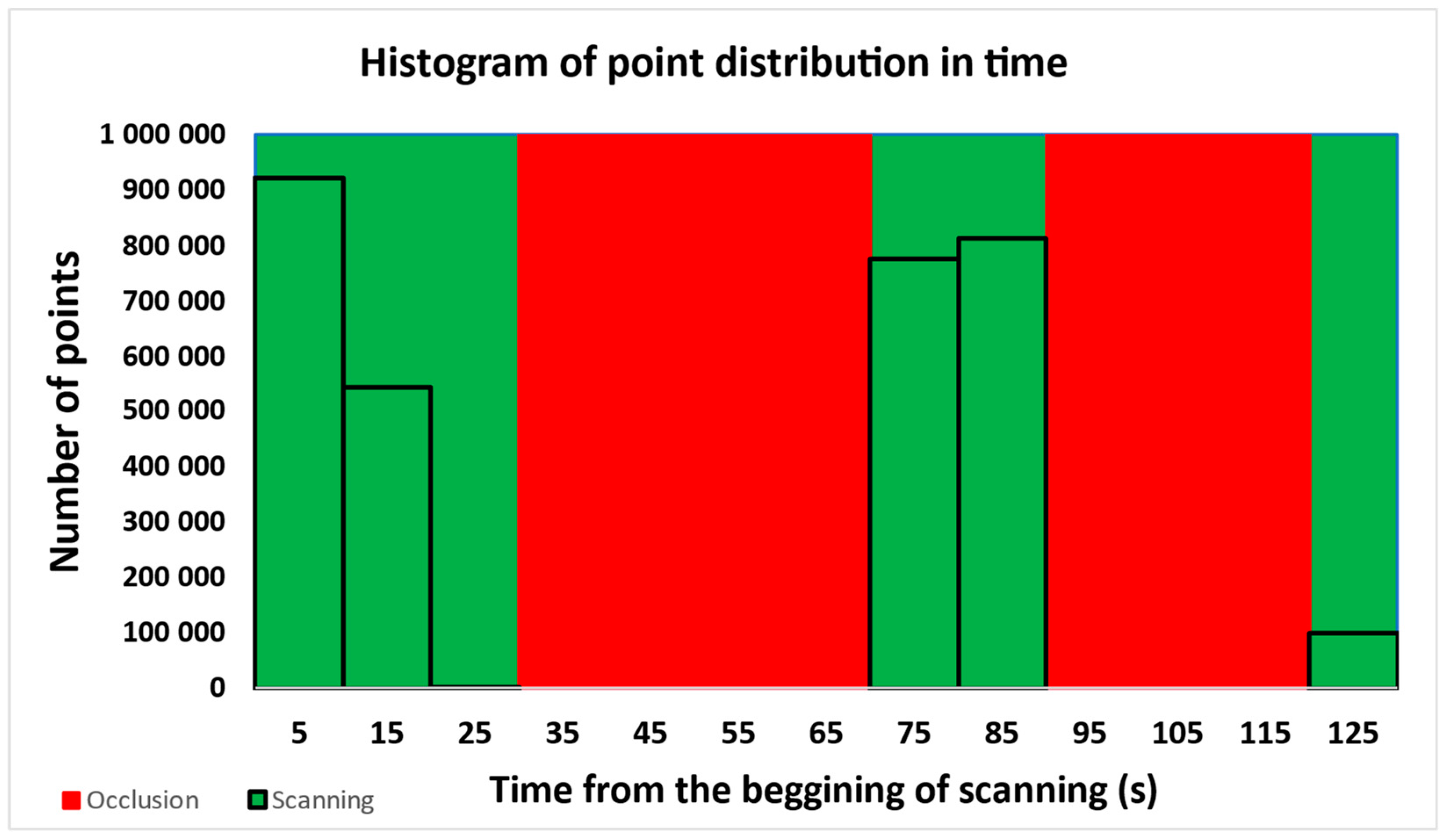
Figure 1. Example of the point distribution in time. The histogram area is divided into two sections: 1. scanning time periods (green) and 2. occlusion time periods (red).
Remotesensing 16 01734 g001
Figure 2. The Hrabiny-South study site, with its location within the Slovak Republic in the lower right corner. The sampling design used for spatial tiling of the point clouds is shown in the figure (yellow polygons).
Remotesensing 16 01734 g002
Figure 3. The Hrabiny-North study site, with its location within the Slovak Republic in the lower right corner. The sampling design used for spatial tiling of the point clouds is shown in the figure (yellow polygons).
Remotesensing 16 01734 g003
Figure 4. Mobile mapping system RIEGL VMX-250 mounted on Zetor Horal 7245 tractor. Two mobile laser scanners VQ-250 (1) were placed on the side of the MMS measuring head. The GNSS antenna (2) was placed on the top of the measuring head, and the NovAtel® ProPak6 (3) was attached to the tractor cabin.
Remotesensing 16 01734 g004
Figure 5. A point cloud from one of the tiles.
Remotesensing 16 01734 g005
Figure 6. One of the point clouds extracted from the point cloud showed in Figure 5 using GNSS time-based point clustering. The point cloud consists of the highest number of points. The histogram’s part corresponding to the displayed point cloud is highlighted in yellow.
Remotesensing 16 01734 g006aRemotesensing 16 01734 g006b
Figure 7. Scatterplot for the relationship between the optimal bin width and the maximum occlusion duration.
Remotesensing 16 01734 g007
Figure 8. Scatterplots for the relationship between the optimal bin width and the mean scanning duration before and after the transformation by a natural logarithm.
Remotesensing 16 01734 g008
Figure 9. The mobile mapping system’s trajectory and the coverage of the point clouds scanned in the Hrabiny-South study site. Each part of the trajectory corresponds to the point cloud with the same number.
Remotesensing 16 01734 g009
Figure 10. The mobile mapping system’s trajectory and the coverage of the point clouds scanned in the Hrabiny-North study site. Each part of the trajectory corresponds to the point cloud with the same number.
Remotesensing 16 01734 g010
Table 1. Total Number of point clouds by processing stage.
Number of Points
Hrabiny-SouthHrabiny-NorthTotal
Filtering StageScanner 1Scanner 2Scanner 1Scanner 2
Original sample65656969268
Non-empty point clouds65626969265
Successfully processed62626764255
First stage clustering input62626764255
Second stage clustering input77736964283
Optimal bin width < 10077736857275
Table 2. Means, standard deviations, t-values, and F-values for stand-to-stand comparison of processability and additional parameters.
VariablePlotNMeant-Value *STDF-Value **
Threshold (s)Hrabiny-South1503.9081.2639.5837.183
Hrabiny-North1256.03417.743
Number of pointsHrabiny-South1501,495,638.60.0372,353,039.3760.054
Hrabiny-North1251,485,118.0562,359,536.157
Spatial density (pnts/m3)Hrabiny-South1505138.440.3227429.080.001
Hrabiny-North1255421.477032.71
Temporal density (pnts/s)Hrabiny-South15042,650.540.09754,853.250.326
Hrabiny-North12541,998.3656,888.53
Point lossHrabiny-South150451,904.827−0.265835,113.8290.002
Hrabiny-North125479,734.664906,416.109
% Point lossHrabiny-South15039.006−1.50840.090.839
Hrabiny-North12546.21938.797
Time range (s)Hrabiny-South15043.589−1.38440.2921.991
Hrabiny-North12551.15550.37
Total scanning duration (s)Hrabiny-South15035.0630.28625.7547.694
Hrabiny-North12534.25819.924
Mean scan duration (s)Hrabiny-South15024.052−0.42222.7211.401
Hrabiny-North12525.24424.014
Total duration of occlusions (s)Hrabiny-South1508.525−1.92225.70415.079
Hrabiny-North12516.89845.335
Max duration of occlusion (s)Hrabiny-South1506.167−1.1816.4596.13
Hrabiny-North1259.27626.762
Number of outagesHrabiny-South15045.787−2.12889.42210.823
Hrabiny-North12575.04136.933
Mean PDOPHrabiny-South15014.8670.32418.9080.008
Hrabiny-North12514.11916.994
Max outage (s)Hrabiny-South15011.401−0.3717.4254.824
Hrabiny-North12511.90114.388
Mean outage (s)Hrabiny-South1502.618−0.8813.2595.978
Hrabiny-North1252.2614.591
* t-values from the independent-samples t-test, the critical value for df = 273 and α = 0.05 is 1.65. ** F-values from Levene’s test for equality of variances, the critical value for df1 = 1, df = 273 and α = 0.05 is 3.876. Characteristics with significant differences between the two sites are highlighted in bold font.
Table 3. The best-fitting models for the relationships between the optimal bin width and the point cloud parameters related to point distribution.
VariableLN (Number of Points)LN (Temporal Density)LN (Spatial Density)
F-value70.156243.54557.032
F-critical3.84153.84153.8415
R20.2040.4710.173
Best-fitting modelLinearLinearLinear
b coeficient sign---
Table 4. The best-fitting models for the relationships between the optimal bin width and the time-related point cloud parameters.
VariableStatitsticF-ValueF-CriticalR2Modelb Coef. Sign
Time rangeTotal415.1913.84150.603Linear+
LN (Scanning duration)Total19.3583.84150.066Power+
Mean257.4363.84150.485Power
Max10.7093.84150.038Power
Occlusion durationTotal870.3353.84150.761Linear+
Mean114.8273.84150.296Linear+
Max2856.4923.84150.913Linear+
Table 5. The best-fitting models for the relationships between the optimal bin width and the statistics of the GNSS signal outage durations.
VariableStatitsticF-ValueF-CriticalR2Modelb Coef. Sign
Overall outageNumber48.5023.84150.151Linear+
Mean3.3223.84150.012Exp+
Max82.6963.84150.232Linear+
Outage during the scanningNumber12.0553.84150.042Linear+
Mean8.5153.84150.03Exp
Max0.1173.84150Exp
Outage during the occlusionNumber138.6683.84150.337Linear+
Mean3.9583.84150.057Power+
Max400.6513.84150.595Linear+
Disclaimer/Publisher’s Note: The statements, opinions and data contained in all publications are solely those of the individual author(s) and contributor(s) and not of MDPI and/or the editor(s). MDPI and/or the editor(s) disclaim responsibility for any injury to people or property resulting from any ideas, methods, instructions or products referred to in the content.