Article

Three-Dimensional Surface Deformation of the 2022 Mw 6.6 Menyuan Earthquake from InSAR and GF-7 Stereo Satellite Images

1
State Key Laboratory of Earthquake Dynamics, Institute of Geology, China Earthquake Administration, Beijing 100029, China
2
Shanghai Earthquake Agency, Shanghai 200062, China
3
Shanghai Sheshan National Geophysical Observatory, Shanghai 201602, China
*
Author to whom correspondence should be addressed.
Remote Sens. 2024, 16(12), 2147; https://doi.org/10.3390/rs16122147
Submission received: 23 April 2024 / Revised: 7 June 2024 / Accepted: 8 June 2024 / Published: 13 June 2024
(This article belongs to the Topic Advances in Earth Observation and Geosciences)

Abstract

:
Three-dimensional coseismic surface deformation fields are important for quantifying the geometric and kinematic characteristics of earthquake rupture faults. However, traditional geodetic techniques are constrained by intrinsic limitations: Interferometric synthetic aperture radar (InSAR) can only extract far-field deformation fields owing to incoherence; global navigation satellite systems (GNSSs) can only acquire displacement at discrete points. The recently developed optical pixel correlation technique, which is based on high-resolution remote sensing images, can acquire near-field coseismic horizontal deformation. In this study, InSAR line-of-sight (LOS) and azimuth direction far-field deformation, horizontal near-field deformation determined using optical pixel correlation based on pre- and post-earthquake GaoFen (GF)-2/7 images, and vertical deformation determined by differencing pre- and post-earthquake GF-7 digital elevation models (DEMs) were combined to comprehensively provide the three-dimensional deformation field of the 2022 Mw 6.6 Menyuan earthquake. The results show that the near-field deformation field calculated by optical pixel correlation quantified displacements distributed over the rupture fault zone, which were not available from the InSAR deformation maps. We identified significant vertical displacements of ~1–1.5 m at a bend region, which were induced by local compressive stress. The maximum uplift (>2.0 m) occurred near the epicenter, on the southern sides of the main and secondary faults along the middle segment of the ruptured Lenglongling fault. In addition, surface two-dimensional strain derived from the displacement maps calculated by optical pixel correlation revealed high strain concentration on the rupture fault zone. The method described herein provides a new tool for a better understanding of the characteristics of coseismic surface deformation and rupture patterns of faults.

1. Introduction

On 8 January 2022, a Mw 6.6 earthquake occurred in Menyuan County, Qinghai Province, China; moderate to strong earthquakes also occurred in Menyuan County in 1986 (Mw 6.0) and 2016 (Mw 5.9) [1]. The epicenter of the 2022 earthquake was reported to be at 101.260°E and 37.770°N by the China Earthquake Networks Center (CENC), and the depth was 10 km (Figure 1). Focal mechanism solutions indicated that it was predominantly a left-lateral slip event. The earthquake ruptured the Lenglongling fault (LLLF) and Tuolaishan fault (TLSF) [1], which belong to the Qilian–Haiyuan fault system on the northeastern margin of the Tibetan Plateau [2,3]. Movement patterns in this region are dominated by strike-slip (Qilian–Haiyuan fault) and thrust (North Tuolaishan fault, Sunan–Qilian fault, North Qilian thrust faults) faults that have produced strong earthquake activity, including the 1920 Mw 7.9 Haiyuan earthquake [4] and 1927 Mw 8.0 Gulang earthquake [5].
The 2022 Mw 6.6 Menyuan earthquake caused severe coseismic surface ruptures, including surface cracks and the collapse of a Lanzhou–Xinjiang Railway bridge and tunnel. The maximum coseismic horizontal displacements measured in the field were 2.6–3.7 m [1,6,7,8]. In addition, newly published detailed field survey data indicated that the earthquake broke the junctions of the LLLF with the Sunan–Qilian (SN–QLF) and North Tuolaishan (NTLSF) faults [6]. A secondary fault on the north of the middle rupture segment of the LLLF was traced and produced 0.47 m of vertical displacement [8]. In summary, the rupture pattern was complex and the magnitude of surface displacement was considerable. Deformation in the line-of-sight (LOS) and azimuth directions has been determined based on interferometric synthetic aperture radar (InSAR) using Sentinel-1 and Advanced Land Observation Satellite-2 (ALOS-2) data [9,10,11]. In addition, three-dimensional surface deformation fields have been solved using the strain model and variance component estimation (SM–VCE) method based on SAR data, which indicated maximum horizontal and vertical displacements of 1.9 and 0.6 m, respectively [9].
Quantitative measurements of coseismic surface displacement, which have always been the focus of earthquake research, are effectively conducted through traditional field surveys, accurately identifying surface rupture traces and measuring the surface displacements recorded by offset landforms [12,13,14,15,16,17]. The developments of high-resolution optical satellites, Light Detection and Ranging (LiDAR), and other remote sensing technologies, such as Unmanned Aerial Vehicle (UAV) photogrammetry combined with satellite interferometry, have greatly improved the mapping of field coseismic rupture measurements [18,19,20,21,22,23]. In addition, the InSAR technology allows for rapid acquisition of surface deformation, from coseismic and early post-seismic deformation to ground deformations during seismic sequence until predicting the mainshock anticipated by intra-sequence ground deformations [24,25,26]. However, InSAR data can suffer from incoherence, especially in coseismic rupture fault zones; this absence of near-fault displacement data results in discrepancies between field measurements and InSAR observations. Global navigation satellite system (GNSS) observations are commonly too sparse to capture the complete deformation field across the full fault rupture zone [27,28,29]. Recently, the development of optical pixel correlation based on high-resolution optical remote sensing data has enabled the acquisition of near-fault deformation fields [30,31]. Using this method, a number of studies have revealed both displacements localized to within tens of meters of the surface trace of the fault and distributed off-fault deformation (OFD) extending tens to hundreds of meters away from the surface trace, which are difficult to acquire from InSAR or field measurements [32,33,34,35,36,37,38].
We previously acquired the horizontal deformation field of the 2022 Mw 6.6 Menyuan earthquake based on GaoFen-2/7 (GF-2/7) stereo satellite images and performed quantitative measurements of the OFD [38]. In this study, we comprehensively solved the complete three-dimensional surface deformation field of the 2022 Mw 6.6 Menyuan earthquake by incorporating published InSAR [9] and optical pixel correlation [38] observations with the vertical deformation field by this study determined from the difference between pre- and post-earthquake digital elevation models (DEMs) using GF-7 stereo satellite images. Then, the kinematic characteristics of the earthquake were obtained by analyzing the three-dimensional deformation field. In addition, two-dimensional strain fields were derived from surface horizontal displacement maps calculated based on optical pixel correlation.

2. Data and Methods

2.1. Data

We collected pre- and post-2022 Mw 6.6 Menyuan earthquake GF-7 stereo images from the High-resolution Remote Sensing Data Center of the China Earthquake Administration (Table 1). Differential InSAR (DInSAR) LOS and azimuth direction deformation from pixel offset-tracking (POT), multiple aperture InSAR (MAI), and burst overlap InSAR (BOI) were acquired from Liu et al. [9]. Near-field horizontal E–W deformation was taken from Han et al. [38]. Vertical deformation data were processed in this study (Table 2).

2.2. Vertical Displacement Calculation

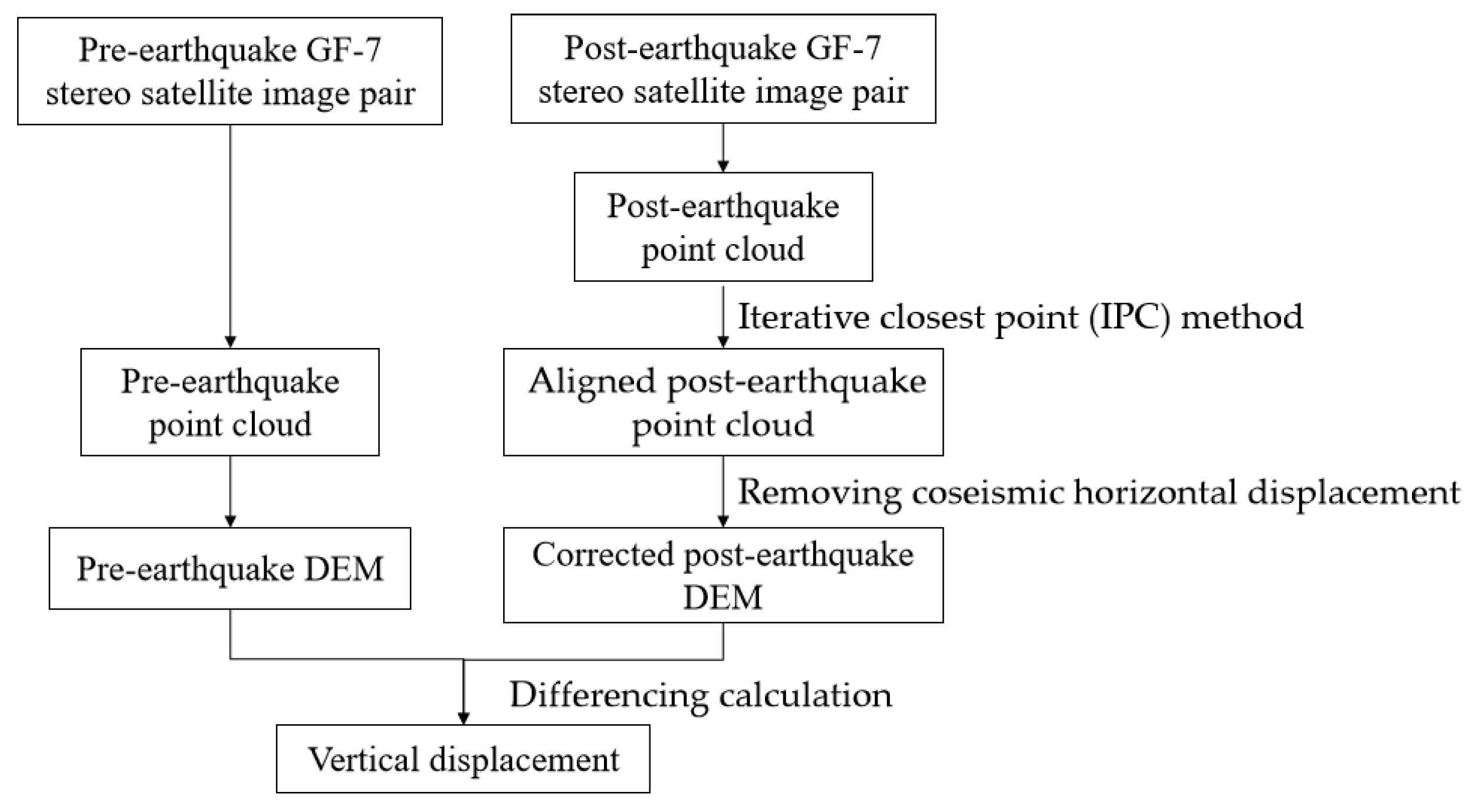
High-density point cloud data were obtained by processing GF-7 stereo satellite image pairs before and after the earthquake based on the software ENVI 6.0. The post-earthquake point clouds were aligned to the pre-earthquake point clouds using the iterative closest point (IPC) method, which was designed to process LiDAR point cloud data [39], in the open-source software Cloud Compare v2.10.2 (accessed on 1 April 2022, https://www.cloudcompare.org/). Next, the point clouds were meshed to 1 × 1 m spatial resolution DEMs. Earthquake-induced terrain changes were attributed to both horizontal and vertical displacements; therefore, in order to determine the real vertical displacement, the post-earthquake DEM was corrected for coseismic horizontal displacement; that is, horizontal displacement determined by optical pixel correlation of GF-2/7 was removed. Finally, the coseismic vertical deformation field was obtained by subtracting the pre-earthquake DEM from the rectified post-earthquake DEM. The data treatment flow is shown in Figure 2.

2.3. Calculation of Three-Dimensional Coseismic Surface Deformation Fields

According to the geometry of SAR satellite observations, the relationships between InSAR LOS and azimuth direction displacements and three-dimensional ground surface deformation were determined using Equations (1) and (2), respectively:
d L O S = d U cos θ sin θ d N cos α 3 π / 2 + d E sin α 3 π / 2
d A Z I = d N sin α 3 π / 2 d E cos ( α 3 π / 2 )
where d L O S and d A Z I are LOS and azimuth direction displacements from InSAR, respectively; θ and α 3 π / 2 are the angels of incidence and azimuth of SAR satellite observations, respectively; and d E ,   d N ,   d U are the ground surface E–W, N–W, and vertical direction displacements, respectively. Horizontal E–W displacement was that calculated by optical pixel correlation based on the GF-2/7 images. Coseismic surface vertical displacement was calculated by DEM differencing. We constructed a matrix of relationships among the directional deformation obtained by each method. Finally, by solving matrix Equation (3) via the least-squares method, the complete three-dimensional surface deformation field, incorporating both the near- and far-field, was derived.
sin θ sin α 3 π / 2   L O S sin θ cos ( α 3 π / 2 )   L O S cos θ L O S cos ( α 3 π / 2 ) A Z I sin ( α 3 π / 2 ) A Z I 0 0 1 G F E W 0 0 0 0 1 G F U N d E d N d U = d L O S d A Z I d G F E W d G F U N

3. Results

3.1. Vertical Displacement from DEM Differencing

Figure 3a illustrates the vertical deformation field of the 2022 Mw 6.6 Menyuan earthquake obtained by differencing the pre- and post-earthquake DEMs. The southern sides of the rupture faults were uplifted relative to the northern sides. Along the main coseismic ruptures of the LLLF, two regions showed significant vertical displacements: (1) a fault bend on the western segment of the main ruptured LLLF, where notable vertical displacement can be attributed to local compressive stress induced by right-step left-lateral strike-slip movement, that is, a transpression zone (push-up) with a right an echelon step caused by the left strike-slip fault (Figure 3b); and (2) the epicenter on the middle segment of the main ruptured LLLF, where serious ground damage was reported, including the collapse of a Lanzhou–Xinjiang Railway tunnel and bridge.
We extracted the displacement profiles across both sides of the rupture faults and calculated the relative vertical displacements of the southern side compared with the northern side. The vertical displacement measurement results are as follows: (1) Vertical displacement at the fault bend region on the western segment of the main rupture fault (LLLF) was ~1–1.5 m (Figure 3c–e,i); and (2) at the epicenter region on the middle segment of rupture fault (LLLF), relative vertical displacement occurred simultaneously on both the main rupture fault and a secondary fault to the north. Specifically, relative vertical displacement along the main rupture on the LLLF was ~1–2.3 m (Figure 3f,g,i), while that along the secondary fault was ~0.3–0.8 m (Figure 3f,g,i), which is consistent with field measurements [8]. On the eastern end of the secondary rupture fault, we measured a relative vertical displacement of ~1 m (Figure 3h,i). In addition, Figure 3i shows the comparison of the relative vertical displacements measured in this study with those measured in the field. It was interesting to note that at the western end of the secondary fault, the measurements of this study were similar or slightly larger than the field measurements, while at the eastern segment of the secondary rupture, the measurements of this study were larger than the field measurements. The reason for this might be that the field measurements with a tape could only estimate the vertical displacement at the fault scarps, whereas the vertical displacements on both sides of the steep slopes could be obtained by DEM differencing, but they were easily affected by the slope of the terrain [40].

3.2. Three-Dimensional Surface Deformation Fields

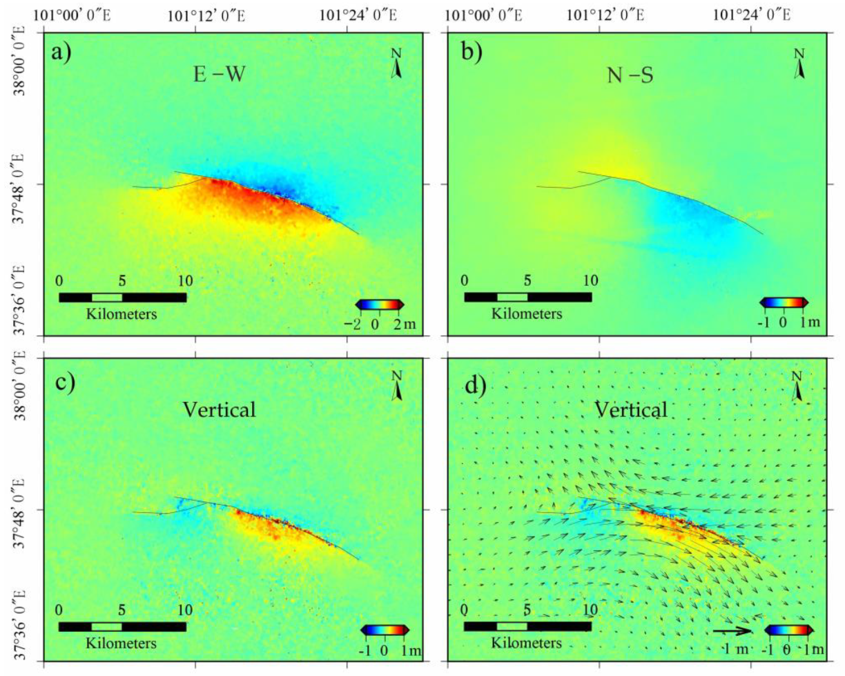
Figure 4 shows the resolved three-dimensional coseismic surface deformation fields of the 2022 Mw 6.6 Menyuan earthquake as determined from multiple remote sensing datasets versus the three-dimensional coseismic surface deformation fields resolved only by InSAR in Figure S1 (referencing Figures S2 and S3 for the raw, simulated, and residual data). E–W deformation (Figure 4a) was the largest, reaching 2 m, while N–S (Figure 4b) and vertical (Figure 4c) deformation were approximately 1 m. E–W deformation had a homogeneous distribution pattern, while N–S deformation had an inhomogeneous distribution pattern. Specifically, along the western segment of the LLLF and the eastern end of TLSF coseismic ruptures, both sides of the ruptured fault moved in a northward direction. However, in the middle and eastern segments of the ruptured LLLF, the southern side of the rupturing fault displayed obvious southward movement. Vertical deformation featured two contrasting centers of uplift–subsidence. Specifically, the southern side of the TLSF coseismic rupture exhibited subsidence, while the southern side of the LLLF main rupture exhibited uplift, which was consistent with the coseismic vertical displacement from DEM differencing (see Section 3.1). Horizontal displacement was composed of both E–W and N–S components (Figure 4d), showing clockwise rotational movement of the relative left-lateral slip on the two sides of the rupture fault.

4. Discussion

4.1. Characteristics of Near-Field Deformation

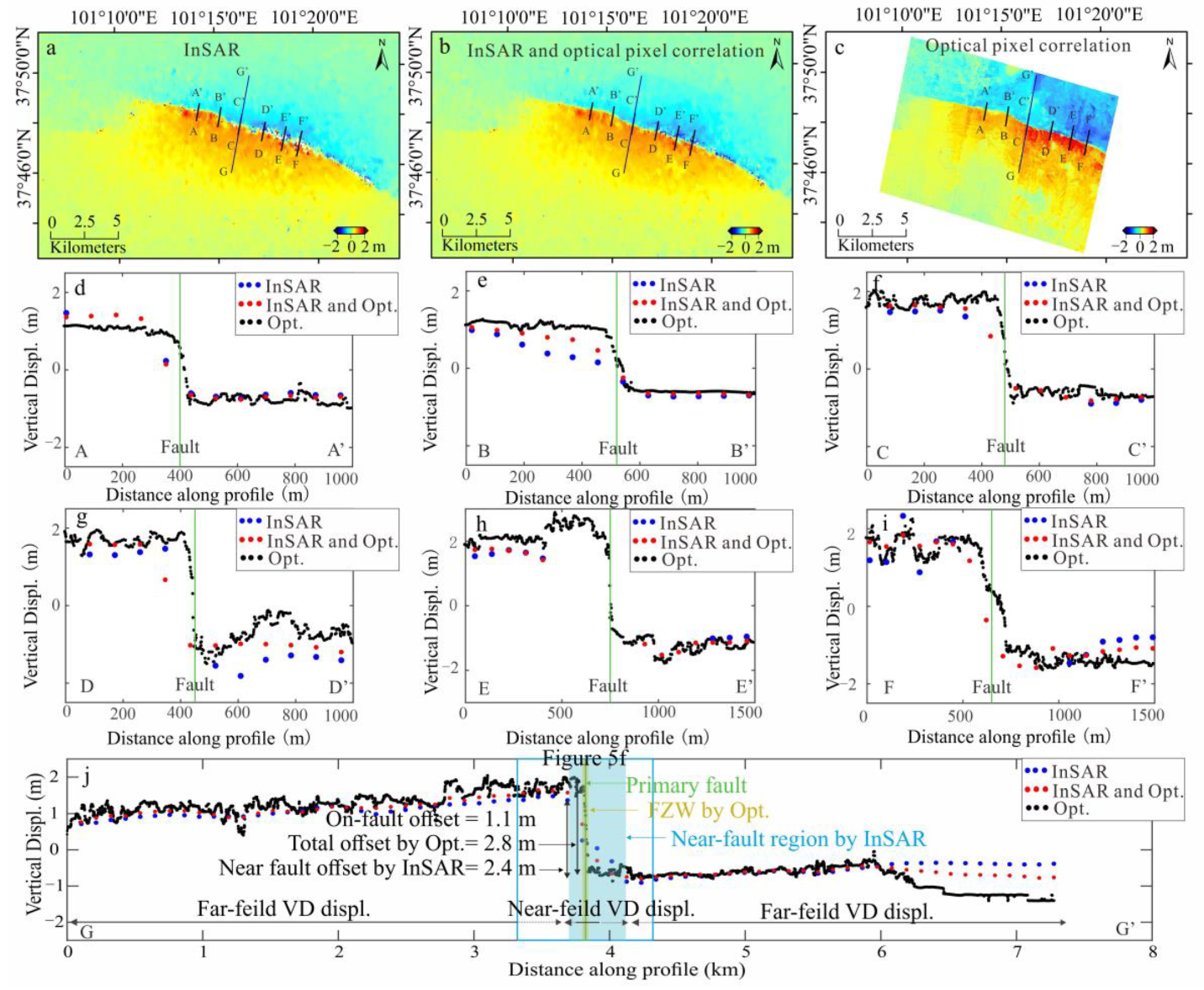
In this study, we obtained the complete three-dimensional surface deformation field of the 2022 Mw 6.6 Menyuan earthquake by incorporating near- and far-field deformation data (Figure 4) from different data sources. The aim was to generate a more comprehensive understanding of the complete deformation field than that provided by traditional InSAR observations alone. We selected the calculated E–W displacement, which was the most significant deformation component, and compared it with the displacement results from both InSAR and optical pixel correlation alone (Figure 5). The magnitudes of N-S and vertical displacement fields were small and did not represent the complete deformation field, so detailed comparisons were not made (Figure 4 and Figure S1).
Displacement profiles at 1–1.5 km spacing across the rupture fault (Figure 5d–i) showed that optical pixel correlation was best able to constrain near-fault deformation (within tens to hundreds of meters away from the surface rupture trace). In contrast, due to the low spatial resolution of the SAR image and low signal-to-noise ratio of the InSAR technology on the near-fault region, InSAR could not accurately depict the near-fault deformation; furthermore, InSAR could not be used to determine the locations of coseismic rupture traces and the width of the fault rupture zone, even the actual relative displacements across the fault rupture zone (Figure 5j). In fact, recent studies have found that the distribution of displacements on coseismic surface rupture zones was very complex [41,42], which contained not only the offset localized on the primary fault (on-fault displacement measured in field survey) but also diffused displacements distributed on both sides of the primary fault (OFD, which was defined as the difference between the total offset measured through optical pixel correlation map and the on-fault offset measured in field survey) [35,38]. Therefore, the relative displacement across the fault rupture zone from the optical pixel correlation map was larger than that from InSAR and field measurements (Figure 5j).
For far-field continuous deformation fields, InSAR has higher measurement accuracy. However, as shown in Figure 5j, the far-field displacement constrained by optical pixel correlation measurement was similar to that of InSAR measurement. Among them, the inconsistency of the data at 6–7 km along the long profile in Figure 5j was due to the effect of clouds on the optical image.
In contrast, the calculation results from the combination of InSAR and optical pixel correlation deformation data provided an intermediate solution, indicating that both datasets provided constraints on the calculation results. However, as the InSAR data were more abundant than the optical pixel correlation data, the joint calculation results were more strongly influenced by the InSAR data. To better constrain the near-field deformation, sufficient optical remote sensing data should be used to extract the coseismic near-field deformation.

4.2. Coseismic Strain

Compared with the displacement maps (Figure 4), the strain fields, which were derived from the displacement maps, provided more insights into the crustal deformation. Generally, geodetic techniques (GNSS and InSAR) are utilized to calculate interseismic deformation and then used to generate the interseismic strain rate field. Based on the accumulation and differences in strain rate distribution along seismological faults, the degree of seismic hazard for different fault segments can be identified [43,44]. To quantify the coseismic strain, the strain tensor can be derived from the surface displacement gradient, and then the dilatation, rotation, and shear strain fields can be obtained by decomposing the strain tensor. The coseismic strain invariants reflect more specific kinematic characteristics and rupture deformation patterns. Dilatation strain indicates contraction and extension deformation, while rotation demonstrates rotational deformation. The maximum shear strain occurs in regions with significant relative displacement, which is mostly concentrated along the rupture zone [45].
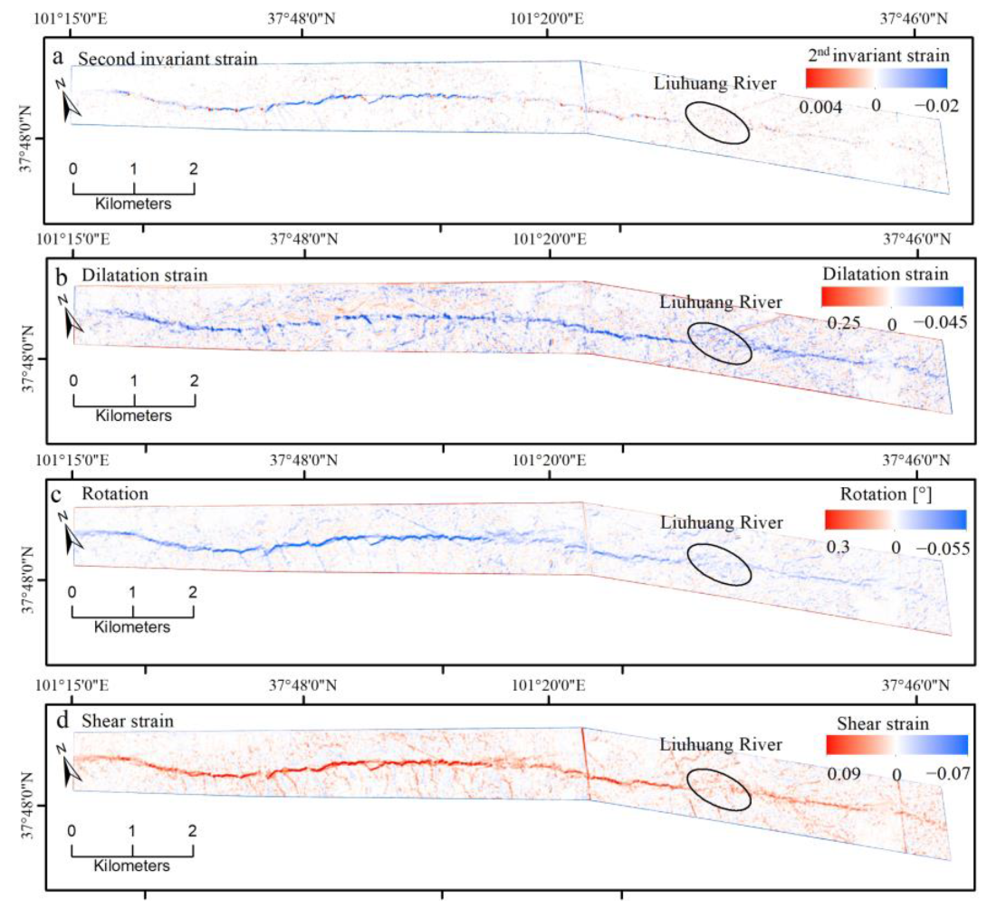
In this study, the horizontal E–W and N–S displacements calculated from optical pixel correlation [38], which were down-sampled to a spatial resolution of 3 × 3 m, were employed to calculate the two-dimensional strain fields of the 2022 Mw 6.6 Menyuan earthquake. We used the software developed by Barnhart et al. [46] with a calculation window of 2 × 2 pixels and a minimum-moment regularization of 0.25; the results are shown in Figure 6. A previous study used the InSAR deformation data to determine the strain fields [9]; however, owing to the very low spatial resolution of the InSAR data, the results could not accurately reflect the strain characteristics of the coseismic rupture fault zone. Therefore, in this study, the InSAR deformation data were not used for the strain calculation.
The strain maps clearly demonstrate high strain along the rupture fault zone of LLLF (Figure 6). Specifically, dilatation strain along the rupture zone was negative, indicating that the coseismic deformation had an extrusion component (Figure 6b). The negative values of rotational strain (Figure 6c) indicated a relative clockwise motion of the two sides of the rupture fault, which was consistent with the three-dimensional displacement field results (Figure 4d). The shear strain (Figure 6d) showed ground rupture traces with prominent relative displacements along the rupture zone. In summary, the strain maps clearly revealed the traces of large strike-slip ruptures.
The signs (positive vs. negative) of the strain components remained consistent along the rupture fault zone of LLLF, suggesting that the stress state was not subjected to reverse changes due to variations in the stress environment or local geometric structure. Along the eastern segment of the main rupture of the LLLF, the strain distribution was dispersed, especially where the rupture passed across the Liuhuang River. The coseismic shear strain values were much larger than the commonly assumed upper threshold of 0.5% yield strain for rocks in a laboratory setting [47]. These findings suggest that the factors influencing the ruptures along the fault zone were complex.
The surface deformation and strain distributions along fault zones differ depending on fault structural maturity. For example, the 2021 Mw 7.4 Maduo earthquake occurred on immature faults, and some studies have suggested that the coseismic shear strain was less than the 0.5% laboratory threshold [48]; however, for the same earthquake, Li et al. [49] proposed a coseismic rupture strain threshold of 0.5–1.5% based on shear strain derived from the deformation field calculated using SPOT optical satellite images. The most important difference was the type of deformation data used by the above two researchers. The former used InSAR far-field deformation field data, while the latter used near-field deformation fields calculated with the optical pixel correlation method to calculate the strain distributed over the rupture zone.
According to our previous study [38], the seismogenic fault of the 2022 Mw 6.6 Menyuan earthquake, the LLLF, is a mature fault. On this basis, the large coseismic shear strain along the 2022 Mw 6.6 Menyuan earthquake surface rupture zone is reasonable. However, the assessment of coseismic strain thresholds for mature and immature ruptures requires further study.

5. Conclusions

In this study, we comprehensively solved the three-dimensional surface deformation field of the 2022 Mw 6.6 Menyuan earthquake by combining surface deformation fields determined from multi-source remote sensing data and methods, including InSAR LOS and azimuth direction deformation based on Sentinel-1 and ALOS-2 data, surface horizontal deformation from optical pixel correlation based on GF-2/7 satellite data, and vertical deformation from DEM differencing based on pre- and post-earthquake GF-7 stereo image pairs. Firstly, pre- and post-earthquake topographic point cloud data were extracted based on the GF-7 stereo image pair data. Then, the pre- and post-earthquake point clouds were aligned and gridded into DEMs with a spatial resolution of 1 × 1 m. After removing the impact of coseismic horizontal displacement, the coseismic vertical deformation field was obtained by DEM differencing. The coseismic vertical deformation field revealed two regions with significant vertical displacement: (1) vertical displacement due to local compressive stress at a bend characterized by right-step left-lateral strike slip, and (2) significant uplift to the south of both the main and secondary rupture faults in the epicenter area. The optical pixel correlation method, which is based on very high spatial resolution satellite images, provided exhaustive constraints on near-field deformation. In contrast, the near-field InSAR data were subject to incoherence and low resolution, prohibiting the characterization of deformation within the coseismic rupture zone. Therefore, to obtain a complete three-dimensional surface deformation field, abundant high spatial resolution optical images are needed to provide near-field deformation constraints. Finally, the two-dimensional coseismic strain fields were derived based on the high spatial resolution deformation field calculated using optical pixel correlation. The results showed high strain concentration along the coseismic rupture zone, especially in the shear strain map, which could clearly recognize the surface rupture traces.
In conclusion, this study demonstrates that a single technical means or data source introduces limitations in understanding the characteristics and patterns of coseismic surface rupture deformation. However, the application of diverse research methods and data sources provides a more complete picture of earthquake rupture deformation.

Supplementary Materials

The following supporting information can be downloaded at https://www.mdpi.com/article/10.3390/rs16122147/s1, Figure S1: The surface three-dimensional deformation fields resolved with InSAR data. Figures S2–S3: The deformation maps of InSAR raw data, simulated data, and residuals for surface three-dimensional deformation fields calculation with only InSAR data. Figures S4–S5: The deformation maps of InSAR, optical pixel correlation and DEM differencing raw data, simulated data, and residuals for surface three-dimensional deformation fields calculation with InSAR, optical pixel correlation, and DEM differencing data.

Author Contributions

All the authors participated in editing and reviewing the manuscript. Conceptualization, N.H. and G.Z.; methodology, N.H. and H.C.; validation, X.S. and Y.Z.; formal analysis, G.Z. and N.H.; investigation, J.W.; resources, J. W.; data curation, N.H.; writing—original draft preparation, N.H. and G.Z.; writing—review and editing, N.H. and G.Z.; visualization, Y.Z.; supervision, H.C.; project administration, G.Z.; funding acquisition, G.Z. All authors have read and agreed to the published version of the manuscript.

Funding

This study was supported by the Lhasa National Geophysical Observation and Research Station (Grant Number NORSLS22-02).

Data Availability Statement

The original contributions presented in the study are included in the article/supplementary material, further in-quiries can be directed to the corresponding author.

Acknowledgments

The remote sensing data of GF-7 were provided by the High-Resolution Remote Sensing Data Center, China Earthquake Administration. The topographic point clouds were processed by the open-source software Cloud Compare v2.10.2 (https://www.cloudcompare.org/, accessed on 1 April 2022). The figures in this article were made using the Generic Mapping Tools v6.4 software (https://www.generic-mapping-tools.org/, accessed on 1 April 2022).

Conflicts of Interest

The authors declare no conflicts of interest.

References

  1. Pan, J.; Li, H.; Marie-Luce, C.; Liu, D.; Li, C.; Liu, C.; Wu, Q.; Lu, H.; Jiao, L. Coseismic surface rupture and seismogenic structure of the 2022 Ms6.9 Menyuan earthquake, Qinghai Province, China. Acta Geol. Sin. 2022, 96, 215–231. (In Chinese) [Google Scholar]
  2. Tapponnier, P.; Xu, Z.; Roger, F.; Meyer, B.; Arnaud, N.; Wittlinger, G.; Yang, J. Oblique stepwise rise and growth of the Tibet Plateau. Science 2001, 294, 1671–1677. [Google Scholar] [CrossRef] [PubMed]
  3. Deng, Q.; Ran, Y.; Yang, X.; Min, W.; Chu, Q. Active Tectonic Map of China; Seismological Press: Beijing, China, 2007. [Google Scholar]
  4. Ou, Q.; Kulikova, G.; Yu, J.; Elliott, A.; Parsons, B.; Walker, R. Magnitude of the 1920 Haiyuan earthquake reestimated using seismological and geomorphological methods. J. Geophys. Res. Solid Earth 2020, 125, e2019JB019244. [Google Scholar] [CrossRef]
  5. Guo, P.; Han, Z.; Gao, F.; Zhu, C.; Gai, H. A new tectonic model for the 1927 M8. 0 Gulang earthquake on the NE Tibetan Plateau. Tectonics 2020, 39, e2020TC006064. [Google Scholar] [CrossRef]
  6. Wen, Y.; Yuan, D.; Xie, H.; Su, R.; Su, Q.; Li, Z.; Sun, H.; Si, G.; Yu, J.; Chen, Y.; et al. Typical Fine Structure and Seismogenic Mechanism Analysis of the Surface Rupture of the 2022 Menyuan Mw 6.7 Earthquake. Remote Sens. 2023, 15, 4375. [Google Scholar] [CrossRef]
  7. Han, S.; Wu, Z.; Gao, Y.; Lu, H. Surface rupture investigation of the 2022 Menyuan MS 6. 9 Earthquake, Qinghai, China: Implications for the fault behavior of the Lenglongling fault and regional intense earthquake risk. J. Geomech. 2022, 28, 155–168. (In Chinese) [Google Scholar]
  8. Niu, P.; Han, Z.; Li, K.; Lv, L.; Guo, P. The 2022 Mw 6.7 Menyuan Earthquake on the Northeastern Margin of the Tibetan Plateau, China: Complex Surface Ruptures and Large Slip. Bull. Seismol. Soc. Am. 2023, 113, 976–996. [Google Scholar] [CrossRef]
  9. Liu, J.; Hu, J.; Li, Z.; Ma, Z.; Shi, J.; Xu, W.; Sun, Q. Three-Dimensional Surface Displacements of the 8 January 2022 Mw6.7 Menyuan Earthquake, China from Sentinel-1 and ALOS-2 SAR Observations. Remote Sens. 2022, 14, 1404. [Google Scholar] [CrossRef]
  10. Li, Y.; Jiang, W.; Li, Y.; Shen, W.; He, Z.; Li, B.; Li, Q.; Jiao, Q.; Tian, Y. Coseismic Rupture Model and Tectonic Implications of the January 7 2022, Menyuan Mw 6.6 Earthquake Constraints from InSAR Observations and Field Investigation. Remote Sens. 2022, 14, 2111. [Google Scholar] [CrossRef]
  11. Li, Z.; Han, B.; Liu, Z.; Zhang, M.; Yu, C.; Chen, B.; Liu, H.; Du, J.; Zhang, S.; Zhu, W.; et al. Source Parameters and Slip Distributions of the 2016 and 2022 Menyuan, Qinghai Earthquakes Constrained by InSAR Observations. Geomat. Inf. Sci. Wuhan Univ. 2022, 47, 887–897. [Google Scholar]
  12. Bello, S.; Andrenacci, C.; Cirillo, D.; Scott, C.P.; Brozzetti, F.; Arrowsmith, J.R.; Lavecchia, G. High-Detail Fault Segmentation: Deep Insight into the Anatomy of the 1983 Borah Peak Earthquake Rupture Zone (Mw 6.9, Idaho, USA). Lithosphere 2022, 2022, 8100224. [Google Scholar] [CrossRef]
  13. Brozzetti, F.; Boncio, P.; Cirillo, D.; Ferrarini, F.; de Nardis, R.; Testa, A.; Liberi, F.; Lavecchia, G. High-Resolution Field Mapping and Analysis of the August–October 2016 Coseismic Surface Faulting (Central Italy Earthquakes): Slip Distribution, Parameterization, and Comparison with Global Earthquakes. Tectonics 2019, 38, 417–439. [Google Scholar] [CrossRef]
  14. Civico, R.; Pucci, S.; Villani, F.; Pizzimenti, L.; De Martini, P.M.; Nappi, R.; Open EMERGEO Working Group. Surface ruptures following the 30 October 2016 M w 6.5 Norcia earthquake, central Italy. J. Maps 2018, 14, 151–160. [Google Scholar] [CrossRef]
  15. Fletcher, J.M.; Teran, O.J.; Rockwell, T.K.; Oskin, M.E.; Hudnut, K.W.; Mueller, K.J.; Spelz, R.M.; Akciz, S.O.; Masana, E.; Faneros, G.; et al. Assembly of a large earthquake from a complex fault system: Surface rupture kinematics of the 4 April 2010 El Mayor–Cucapah (Mexico) Mw 7.2 earthquake. Geosphere 2014, 10, 797–827. [Google Scholar] [CrossRef]
  16. Testa, A.; Boncio, P.; Di Donato, M.; Brozzetti, F.; Cirillo, D. Mapping the geology of the 2016 Central Italy earth-quake fault (Mt. Vettore–Mt. Bove fault, Sibillini Mts.): Geological details on the Cupi–Ussita and Mt. Bove–Mt. Porche segments and overall pattern of coseismic surface faulting. Field Trips Maps 2019, 11, 1–13. [Google Scholar]
  17. Yu, Z.; Yin, N.; Xiao, P.; Chen, B. Co-Seismic Surface Ruptures of the CE 1738 M 7.6 Dangjiang Earthquake Along the NW Continuation of the Xianshuihe Fault Zone and Tectonic Implications for the Central Tibetan Plateau. Front. Earth Sci. 2022, 10, 810891. [Google Scholar] [CrossRef]
  18. Zielke, O.; Arrowsmith, J.R.; Ludwig, L.G.; Akciz, S.O. High-resolution Topography-derived offsets along the 1857 Fort Tejon earthquake rupture trace, San Andreas Fault. Bull. Seismol. Soc. Am. 2012, 102, 1135–1154. [Google Scholar] [CrossRef]
  19. Oskin, M.E.; Arrowsmith, J.R.; Corona, A.H.; Elliott, A.J.; Fletcher, J.M.; Fielding, E.J.; Gold, P.O.; Garcia, J.J.G.; Hudnut, K.W.; Liu-Zeng, J.; et al. Near-field deformation from the El Mayor–Cucapah earthquake revealed by differential LIDAR. Science 2012, 335, 702–705. [Google Scholar] [CrossRef]
  20. Zhang, C.; Li, Z.; Zhang, S.; Wang, J.; Zhan, W.; Li, X.; Liu, Z.; Du, J.; Peng, J. Surface Ruptures of the 2022 Mw 6.7 Menyuan Earthquake Revealed by Integrated Remote Sensing. Geomat. Inf. Sci. Wuhan Univ. 2022, 47, 1257–1270. [Google Scholar]
  21. Li, K.; Tapponnier, P.; Xu, X.; Kang, W. The 2022, Ms 6.9 Menyuan earthquake: Surface rupture, Paleozoic suture re-activation, slip-rate and seismic gap along the Haiyuan fault system, NE Tibet. Earth Planet. Sci. Lett. 2023, 622, 118412. [Google Scholar] [CrossRef]
  22. Menichetti, M.; Roccheggiani, M.; De Guidi, G.; Carnemolla, F.; Brighenti, F.; Barreca, G.; Monaco, C. Sentinel-1 Interferometry and UAV Aerial Survey for Mapping Coseismic Ruptures: Mts. Sibillini vs. Mt. Etna Volcano. Remote Sens. 2023, 15, 2514. [Google Scholar] [CrossRef]
  23. Gold, P.O.; Oskin, M.E.; Elliott, A.J.; Hinojosa-Corona, A.; Taylor, M.H.; Kreylos, O.; Cowgill, E. Coseismic slip variation assessed from terrestrial lidar scans of the El Mayor–Cucapah surface rupture. Earth Planet. Sci. Lett. 2013, 366, 151–162. [Google Scholar] [CrossRef]
  24. Wang, J.; Zhang, G.; Shan, X.; Zhang, Y. Three-dimensional deformation of the 2008 Gaize earthquakes resolved from InSAR measurements by multiple view angles and its tectonic implications. Seismol. Geol. 2016, 38, 978–986. (In Chinese) [Google Scholar]
  25. Brozzetti, F.; Mondini, A.C.; Pauselli, C.; Mancinelli, P.; Cirillo, D.; Guzzetti, F.; Lavecchia, G. Mainshock Anticipated by Intra-Sequence Ground Deformations: Insights from Multiscale Field and SAR Interferometric Measurements. Geosciences 2020, 10, 186. [Google Scholar] [CrossRef]
  26. Zhu, S.; Wen, Y.; Gong, X.; Liu, J. Coseismic and Early Postseismic Deformation of the 2020 Mw 6.4 Petrinja Earthquake (Croatia) Revealed by InSAR. Remote Sens. 2023, 15, 2617. [Google Scholar] [CrossRef]
  27. Jin, Z.; Fialko, Y.; Zubovich, A.; Schöne, T. Lithospheric deformation due to the 2015 M7.2 Sarez (Pamir) earthquake constrained by 5 years of space geodetic observations. J. Geophys. Res. Solid Earth 2022, 127, e2021JB022461. [Google Scholar] [CrossRef]
  28. Fialko, Y.; Simons, M.; Agnew, D. The complete (3-D) surface displacement field in the epicentral area of the 1999 Mw7.1 Hector Mine earthquake, Southern California, from space geodetic observations. Geophys. Res. Lett. 2001, 28, 3063–3066. [Google Scholar] [CrossRef]
  29. He, P.; Ding, K.; Xu, C. The 2016 Mw 6.7 Aketao earthquake in Muji range, northern Pamir: Rupture on a strike-slip fault constrained by sentinel-1 radar interferometry and GPS. Int. J. Appl. Earth Observ. Geoinform. 2018, 73, 99–106. [Google Scholar] [CrossRef]
  30. Leprince, S.; Musé, P.; Avouac, J.P. In-flight CCD distortion calibration for pushbroom satellites based on subpixel correlation. IEEE Trans. Geosci. Remote Sens. 2008, 46, 2675–2683. [Google Scholar] [CrossRef]
  31. Rosu, A.M.; Pierrot-Deseilligny, M.; Delorme, A.; Binet, R.; Klinger, Y. Measurement of ground displacement from optical satellite image correlation using the free open-source software MicMac. ISPRS J. Photogram. Rem. Sens. 2015, 100, 48–59. [Google Scholar] [CrossRef]
  32. Gold, R.D.; Reitman, N.G.; Briggs, R.W.; Barnhart, W.D.; Hayes, G.P.; Wilson, E. On-and off-fault deformation associated with the September 2013 Mw 7.7 Balochistan earthquake: Implications for geologic slip rate measurements. Tectonophysics 2015, 660, 65–78. [Google Scholar] [CrossRef]
  33. Gold, R.D.; DuRoss, C.B.; Barnhart, W.D. Coseismic surface displacement in the 2019 Ridgecrest earthquakes: Comparison of field measurements and optical image correlation results. Geochem. Geophys. Geosyst. 2021, 22, e2020GC009326. [Google Scholar] [CrossRef]
  34. Zinke, R.; Hollingsworth, J.; Dolan, J.F.; Dissen, R.V. Three-dimensional surface deformation in the 2016 MW 7.8 Kaikōura, New Zealand, earthquake from optical image correlation: Implications for strain localization and long-term evolution of the Pacific-Australian plate boundary. Geochem. Geophys. Geosyst. 2019, 20, 1609–1628. [Google Scholar] [CrossRef]
  35. Milliner, C.; Donnellan, A.; Aati, S.; Avouac, J.-P.; Zinke, R.; Dolan, J.F.; Wang, K.; Bürgmann, R. Bookshelf kinematics and the effect of dilatation on fault zone inelastic deformation: Examples from optical image correlation measurements of the 2019 Ridgecrest earthquake sequence. J. Geophys. Res. Solid Earth 2021, 126, e2020JB020551. [Google Scholar] [CrossRef]
  36. Scott, C.; Champenois, J.; Klinger, Y.; Nissen, E.; Maruyama, T.; Chiba, T.; Arrowsmith, R. The 2016 M7 Kumamoto, Japan, earthquake slip field derived from a joint inversion of differential lidar topography, optical correlation, and InSAR surface displacements. Geophys. Res. Lett. 2019, 46, 6341–6351. [Google Scholar] [CrossRef]
  37. Li, C.; Li, T.; Shan, X.; Zhang, G. Extremely Large Off-Fault Deformation during the 2021 Mw 7.4 Maduo, Tibetan Plateau. Earthquake. Seismol. Res. Lett. 2023, 94, 39–51. [Google Scholar] [CrossRef]
  38. Han, N.; Zhang, G.; Shan, X.; Zhang, Y.; Hetland, E.; Qu, C.; Gong, W.; Sun, G.; Li, C.; Fan, X.; et al. Coseismic Surface Horizontal Deformation of the 2022 Mw 6.6 Menyuan, Qinghai, China, Earthquake from Optical Pixel Correlation of GF-7 Stereo Satellite Images. Seismol. Res. Lett. 2023, 94, 1747–1760. [Google Scholar] [CrossRef]
  39. Nissen, E.; Krishnan, A.K.; Arrowsmith, J.R.; Saripalli, S. Three-dimensional surface displacements and rotations from differencing pre- and post-earthquake LiDAR point clouds. Geophys. Res. Lett. 2012, 39, L16301. [Google Scholar] [CrossRef]
  40. Zhou, Y.; Parsons, B.; Elliott, J.R.; Barisin, I.; Walker, R.T. Assessing the ability of Pleiades stereo imagery to determine height changes in earthquakes: A case study for the El Mayor-Cucapah epicentral area. J. Geophys. Res. Solid Earth 2015, 120, 8793–8808. [Google Scholar] [CrossRef]
  41. Nelson, M.R.; Jones, C.H. Paleomagnetism and crustal rotations along a shear zone, Las Vegas Range, southern Nevada. Tectonics 1987, 6, 13–33. [Google Scholar] [CrossRef]
  42. Shelef, E.; Oskin, M. Deformation processes adjacent to active faults: Examples from eastern California. J. Geophys. Res. Solid Earth 2010, 115, B05308. [Google Scholar] [CrossRef]
  43. Fialko, Y. Interseismic strain accumulation and the earthquake potential on the southern San Andreas fault system. Nature 2006, 441, 968–971. [Google Scholar] [CrossRef]
  44. Shen, Z.K.; Jackson, D.D.; Kagan, Y.Y. Implications of geodetic strain rate for future earthquakes, with a five-year forecast of M5 earthquakes in southern California. Seismol. Res. Lett. 2007, 78, 116–120. [Google Scholar] [CrossRef]
  45. Zhao, D.; Qu, C.; Chen, H.; Shan, X.; Song, X.; Gong, W. Tectonic and geometric control on fault kinematics of the 2021 Mw7. 3 Maduo (China) earthquake inferred from interseismic, coseismic, and postseismic InSAR observations. Geophys. Res. Lett. 2021, 48, e2021GL095417. [Google Scholar] [CrossRef]
  46. Barnhart, W.D.; Gold, R.D.; Hollingsworth, J. Localized fault-zone dilatancy and surface inelasticity of the 2019 Ridgecrest earthquakes. Nat. Geosci. 2020, 13, 699–704. [Google Scholar] [CrossRef]
  47. Lockner, D.A. A generalized law for brittle deformation of Westerly granite. J. Geophys. Res. Solid Earth 1998, 103, 5107–5123. [Google Scholar] [CrossRef]
  48. Zhao, D.; Qu, C.; Bürgmann, R.; Shan, X. Characterizing Deep, Shallow, and Surface Fault Zone Deformation of the 2021 Mw 7.4 Maduo, China, Earthquake. Seismol. Res. Lett. 2024, 95, 277–287. [Google Scholar] [CrossRef]
  49. Li, C.; Li, T.; Hollingsworth, J.; Zhang, Y.; Qian, L.; Shan, X. Strain threshold for the formation of coseismic surface rupture. Geophys. Res. Lett. 2023, 50, e2023GL103666. [Google Scholar] [CrossRef]
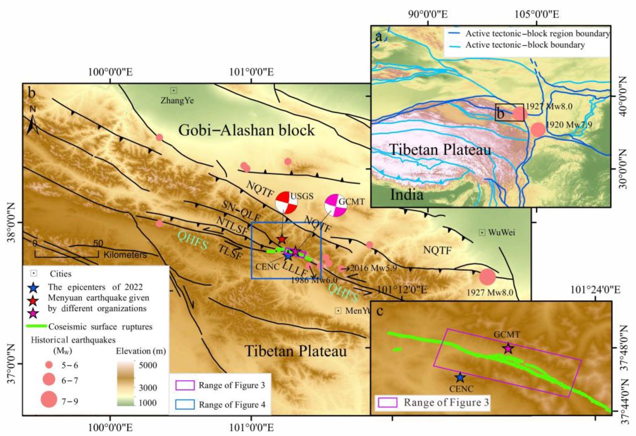
Figure 1. (a) Location of this study area. (b) Tectonic setting of the 2022 Mw 6.6 Menyuan earthquake. The earthquake occurred within the western segment of the Qilian–Haiyuan fault system, located on the northeast margin of the Tibetan Plateau. The earthquake mainly ruptured the western segment of the Lenglongling fault (LLLF) and the eastern end of the Tuolaishan fault (TLSF). Green lines denote coseismic rupture traces. Pink dots denote historical moderate–strong earthquakes, including the 1927 Mw 8.0 Gulang earthquake, 1986 Mw 6.0 earthquake, and 2016 Mw 5.9 Menyuan earthquake. The purple rectangular box represents the range of Figure 3. The blue rectangular box represents the range of Figure 4. NQTF: North Qilian thrust fault; SN–QLF: Sunan–Qilian fault; NTLSF: North Tuolaishan fault; QHFS: Qilian–Haiyuan fault system. (c) Range of Figure 3.
Remotesensing 16 02147 g001
Figure 2. Workflow of the vertical displacement calculation.
Remotesensing 16 02147 g002
Figure 3. (a) Vertical displacement field obtained by differencing pre- and post-earthquake digital elevation models (DEMs). Ovals denote regions with significant vertical displacement, one at a bend region on the western segment of the main rupture of the LLLF and one at the epicenter region on the ruptured middle segment of the LLLF. (b) Vertical movement induced by local compressive stress at the bend owing to right-step left-lateral strike-slip movement. (ce) Relative vertical displacement along profiles across the bend region. (fh) Relative vertical displacement in the epicenter region on (f,g) the main and secondary faults and (h) at the eastern end of the secondary rupture fault. (i) Comparison of vertical displacements between this study and field measurements by Niu et al. [8]. VD: vertical displacement; RVD: relative vertical displacement.
Remotesensing 16 02147 g003
Figure 4. Three-dimensional coseismic surface displacement fields of the 2022 Mw 6.6 Menyuan earthquake derived from the combination of InSAR, optical pixel correlation, and digital elevation model (DEM) differencing. (a) E–W displacement, (b) N–S displacement, (c) vertical displacement, and (d) base map of vertical displacement with arrows showing E–W and N–S displacement components.
Remotesensing 16 02147 g004
Figure 5. E–W displacements of the 2022 Mw 6.6 Menyuan earthquake determined using different methods. (a) E–W displacement map calculated from InSAR data. (b) E–W displacement map calculated by combining InSAR and optical pixel correlation deformation data. (c) E–W displacement map calculated by optical pixel correlation based on GF-2/7 images. (di) E–W displacement profiles at 1–1.5 km intervals across the rupture fault. (j) Long E–W displacement profiles at a 7.5 km interval across the rupture fault. The total offset measured based on the optical pixel correlation map was from Han et al. [38]. On-fault offset measured by field survey was from Pan et al. [1]. Black dots denote E–W displacement calculated by optical pixel correlation, which depicts near-fault deformation. Blue dots denote displacement from InSAR data, for which near-fault information is absent owing to data incoherence. Red dots denote displacement determined by combining the InSAR and optical pixel correlation deformation data. Opt.: optical pixel correlation; FZW: fault zone width.
Remotesensing 16 02147 g005
Figure 6. Coseismic strain fields derived from surface displacement calculated with optical pixel correlation. (a) Second invariant strain, (b) dilatation strain, (c) rotational strain, and (d) shear strain. Black ovals denote the location at which the coseismic rupture crossed the Liuhuang River.
Remotesensing 16 02147 g006
Table 1. GaoFen-7 stereo satellite images used in this study.
SatelliteDateSpatial Resolution (m)Incidence (°)
Backward/Forward
GF-7202111300.68−5/26
GF-7202201080.68−5/26
Table 2. Surface deformation data used in this study.
SensorOrbit DirectionDateTrackObservation TechnologyDeformation Direction
Sentinel-1 aAscending20211229–20220110T26DInSARLOS
Sentinel-1 aAscending20211229–20220110T26POTLOS
Sentinel-1 aAscending20211229–20220110T26BOIAZI
Sentinel-1 aAscending20220105–20220117T128DInSARLOS
Sentinel-1 aAscending20220105–20220117T128POTLOS
Sentinel-1 aAscending20220105–20220117T128BOIAZI
Sentinel-1 aDescending20211229–20220110T33DInSARLOS
Sentinel-1 aDescending20211229–20220110T33POTLOS
Sentinel-1 aDescending20211229–20220110T33BOIAZI
ALOS-2 aDescending20201212–20220123T41DInSARLOS
ALOS-2 aDescending20201212–20220123T41POTAZI
ALOS-2 aDescending20201212–20220123T41MAIAZI
GF-2/7 b-20211124–20220201/
20211130–20220108
-OPCE-W
GF-7 c-20211130–20220108-DifferencingVertical
DInSAR: differential interferometric synthetic aperture radar; BOI: burst overlap InSAR; POT: pixel offset-tracking; MAI: multiple aperture InSAR; LOS: line-of-sight; AZI: azimuth; OPC: optical pixel correlation; E–W: east–west. Sentinel-1 a and ALOS-2 a data are from Liu et al. [9]. GF-2/7 b data are from Han et al. [38]. GF-7 c data are from this study.
Disclaimer/Publisher’s Note: The statements, opinions and data contained in all publications are solely those of the individual author(s) and contributor(s) and not of MDPI and/or the editor(s). MDPI and/or the editor(s) disclaim responsibility for any injury to people or property resulting from any ideas, methods, instructions or products referred to in the content.