Abstract
In contrast to classic hydrographic cutters, unmanned surface vehicles, due to their size, ease of transport and the equipment installed, enable the performance of quick and cost-effective bottom inspections in various water areas. Thanks to their shallow draught and high manoeuvrability, hydrographic drones are capable of the bathymetric exploration of shallow waters such as harbours, hydrotechnical structures and the areas where classic naval vessels could encounter implementation difficulties. The aim of this paper is to demonstrate, using a selected practical example, the specific ability of an unmanned surface vehicle (USV) to carry out the urgent and immediate inspection of the bottom of a specific water area. The freedom to move between restricted areas, the ease of transport and the satisfactory quality of the surveys make hydrographic drones ideal tools for projects of this type. The referenced study produced a bathymetric map of a section of the seabed adjacent to the quay at which a Search and Rescue (SAR) vessel is moored and regularly, at its permanent fixed location, actuates its propellers. The effect of its propellers is the local deepening of the bottom in two places. The research showed a local decrease in the depth from 5.5 m to less than 7 m, which may threaten the stability of the quay structure. In addition, it was noted that the washed bottom material had been moved approximately 10 m from the quay, causing shallowing in two places and reducing the depth from 5.5 m to 4.7 m. This study demonstrated that the use of USVs for applications of this type is very effective in terms of the implementation time and is economically justified.
1. Introduction
Seabed inspection is one of the main tasks in hydrography. It enables a thorough exploration of the hydrographic conditions prevailing in a particular water area, often including marinas and seaports [1,2]. Knowledge of the bottom depth and topography is essential for the safe operation of vessels, as well as the development and updating of nautical charts [3]. Typical hydrographic vessels perform bathymetric surveys in accordance with current International Hydrographic Organisation standards [1,4], primarily in open water areas, which are characterised by much greater depths than harbours. On the other hand, in coastal areas and harbour basins, the manoeuvring of large vessels is hindered, not only by the limited under-keel clearance but also by the freedom to manoeuvre and the movement of other vessels [5,6].
An alternative to classic hydrographic surveys is the use of USVs. Vessels of this type are unmanned surface vehicles which, by means of the installed survey equipment, are capable of carrying out hydrographic surveys [7,8,9]. They are also capable of carrying out surveys thanks to their apparatus, including a vertical or a multi-beam echo sounder, a GNSS positioning system, sonars, LiDAR (Light Detection and Ranging), and a digital camera [10,11]. In addition, unmanned vessels enable the exploration of seabed topography, water area depths, and other parameters of the marine environment.
When considering various criteria for the classification of unmanned vessels, a distinction can generally be made between single-hull or double-hull designs featuring screw propulsion or hydraulic jet propulsion and powered by electricity or internal combustion [3].
The diversity of USV designs results in their versatility of use and specific manoeuvring characteristics [12]. These vessels are characterised by their small size and are perfectly suited to inspection surveys in small water areas requiring considerable mobility in locations that are difficult to access. On the other hand, unmanned vessels are used for long-term, open-water operations [7,8,13] and are characterised by higher seaworthiness. Figure 1 shows two types of USVs that differ fundamentally in their intended use. The first of them is a sea-going vessel, while the other is designed to operate in small and restricted harbour areas.
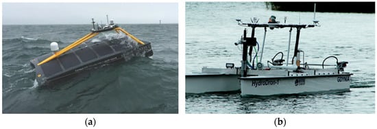
Figure 1.
Unmanned surface vehicles (USVs): a single-hull multifunctional Xocean vessel (a), a double-hull HydroDron vessel (b) [14,15].
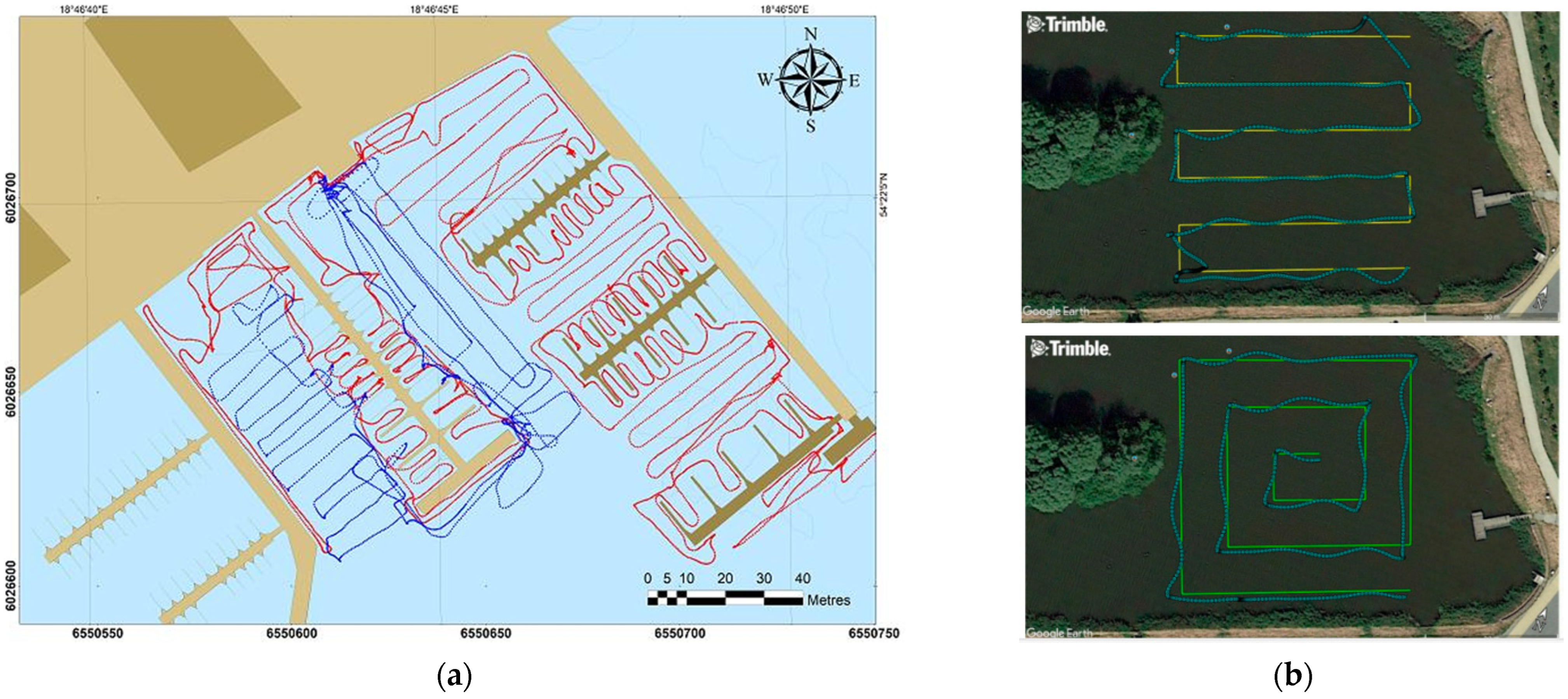
A unique feature of unmanned vessels is that they are capable of carrying out bathymetric surveys in automatic mode, which involves the movement of a drone along pre-planned routes [5,16,17]. This solution does not require the operator to directly control the vessel remotely and increases its directional stability, which results in the uniform distribution of surveys necessary for the preparation of the bathymetric map. On the other hand, when direct control is involved, it is common for small areas with no survey data to emerge between the survey lines. These areas cause difficulties in further data analysis. A comparison of the two control methods (direct and automatic) is presented in Figure 2.
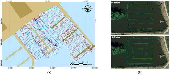
Figure 2.
Examples of USV control. Direct control (a) and automatic control (b) [18,19].
In conclusion, it should be stated that the particular features which distinguish USVs from classic survey vessels (hydrographic cutters and vessels) include their small size and the shallow draught (up to 20 cm), which enables the exploration of water areas that are difficult to access, and, in particular, areas with a depth of even less than 1 m, which are inaccessible to typical hydrographic vessels [11,20]. For this reason, their ability to carry out a quick bottom inspection, without unnecessary time delays and preparations, independently and at any time, is a unique feature of USVs. In addition, automatic control makes USVs an indispensable tool in monitoring and maintaining the technical condition of any water area, including hydro-engineering structures [10,21].
Seaports and marinas are specific areas for new USV applications. One application is the possibility of carrying out an immediate inspection of any water area in the event of an emergency situation that may significantly affect the safety of navigation and the undisturbed operation of the harbour.
It is important for harbour infrastructure to be properly designed, appropriately constructed and adequately maintained in order to meet safety requirements and ensure the operational efficiency of the harbour [22]. Maintaining an appropriate depth of the water area enables access for a variety of marine vessels, especially those with greater draughts, and ensures the safe manoeuvring of vessels within the harbour. Failure to provide adequate depths to vessels in harbours may result in their exclusion from service, which would cause downtime, both in vessel and harbour operations [6,23,24].
A major problem in the operation of harbour basins is the frequent mooring manoeuvres of vessels, which use their own propulsion and control equipment for this purpose, causing gradual degradation of the bottom, which results in localised over-deepened or shallowed water areas. This also causes damage to the systems that reinforce the harbour bottom or the scouring of quays [25]. Due to the intensive use of harbour areas, it is necessary to carry out regular inspections that minimise the risk of failures and limit the occurrence of damage, such as damage to the quay structure as a result of bottom washout or a vessel running aground because of outdated depth data [25,26].
Hence, due to its size, shallow draught and ease of transport, carrying out surveys using a hydrographic drone, moving automatically along bathymetric survey lines, is one of the most effective and increasingly common ways to obtain accurate and reliable measurements of the depth of a water area bottom.
The bathymetric surveys carried out in the vicinity of the quay, referenced in the article, are a typical example of a sudden inspection of a small area where deepening and shallowing have occurred due to the periodic actuation of propellers by a SAR vessel moored at the quay of the National Sailing Centre (NSC) marina in Gdansk.
At the request of the Harbour Master’s Office, a control survey was carried out at the National Sailing Centre of the Gdańsk University of Physical Education and Sport (NSC-GUPES), which allowed bathymetric data for the area to be collected along the quay where the SAR vessel is regularly moored. Based on this, three-dimensional graphical images were prepared. These helped to produce bathymetric images of the bottom, which showed the location of a considerable drop in depth, indicating the emergence of a localised washout of the bottom in the immediate vicinity of the quay, which may affect its stability. The bathymetric survey indicated the need for immediate diagnostic and remedial measures to be taken.
In view of the above, this article had the following aims:
- To demonstrate that the USV, thanks to its special manoeuvring properties and shallow draught, is an optimal tool for carrying out urgent inspections of the bottom in order to ensure the monitoring and maintenance of the technical condition of any water area.
- To propose ways to present the results of bathymetric surveys in shallow areas that enable effective discussion and analysis.
- To show that the proposed method ensures a position accuracy of 0.05 m (p = 0.95) and a depth measurement accuracy of 0.2 m. It meets the requirements of IHO S-44 [1] for port waters Exclusive Order category.
This publication is structured as follows. Section 2, titled “Materials and Methods”, describes the location of the measurement area, characterises the measuring equipment used during the research (USV HyDrone), presents the method of carrying out the measurements and discusses the process of processing the obtained data. Section 3, titled “Results”, presents the obtained bathymetric data in the form of a three-dimensional graphic illustration of the bottom. Section 4, entitled “Discussion”, presents the analysis of the obtained data and answers the following question: is the solution presented in the article, the use of a USV during hydrographic inspections, a good alternative to measurements performed by classic hydrographic units? The article ends with conclusions summarising the research.
2. Materials and Methods
2.1. Measurement Location
The study originated following the information provided by the National Sailing Centre (NSC) Harbour Master, who approached the hydrographic team of the Department of Geodesy and Oceanography at the Gdynia Maritime University with the suspicion that a localised deepening of the bottom had emerged at the quay of his marina, where the rescue vessel is moored. Out of concern for the stability of the quay structure, the Master asked the team to carry out surveys and a bathymetric analysis of this water area.
Hydrographic measurements were carried out in the NSC yacht marina in Gdańsk. It is located on the left shore of the mouth of the Vistula Śmiała river, which creates a natural breakwater in this area. On the opposite side, it borders on an open water area—the Bay of Gdańsk. Figure 3 shows a location of NSC which is placed a few kilometres from Gdańsk city centre, and together with two other marinas, forms a complex of yacht ports. On the right side of the mouth of Vistula Śmiała River, there is the Ptasi Raj nature reserve, occupying the north-western part of Sobieszewska Island [18].
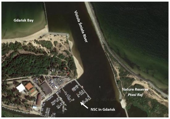
Figure 3.
The location of the National Sailing Centre at the Gdańsk University of Physical Education and Sport (NSC-GUPES).
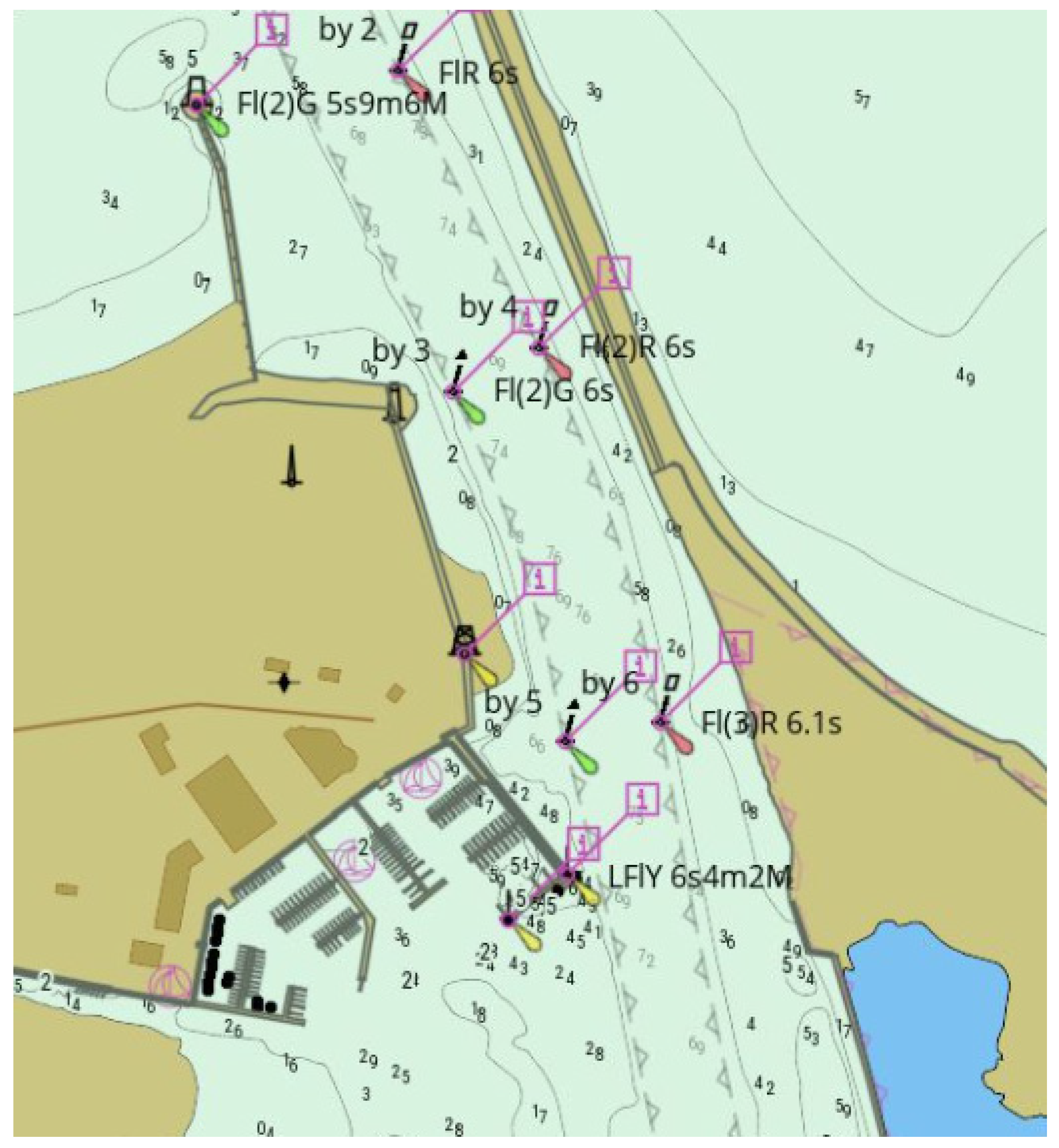
The Vistula Śmiała River is the central part of the Vistula River’s mouth to the Gdańsk Bay. The entrance is protected by a 520 m long breakwater from the reserve side (east) and a 160 m long groyne from the west. The width of the fairway is 35 m. Vessels with a draught exceeding 2.5 m heading to the marina should report to the port boatswains in the marinas at each entrance in order to obtain current navigation and bathymetric information [18]. The approach to NSC-GUPES shows Figure 4.

Figure 4.
Map including depths and navigation markings of the approach to the National Sailing Centre at the Gdańsk University of Physical Education and Sport (NSC-GUPES).
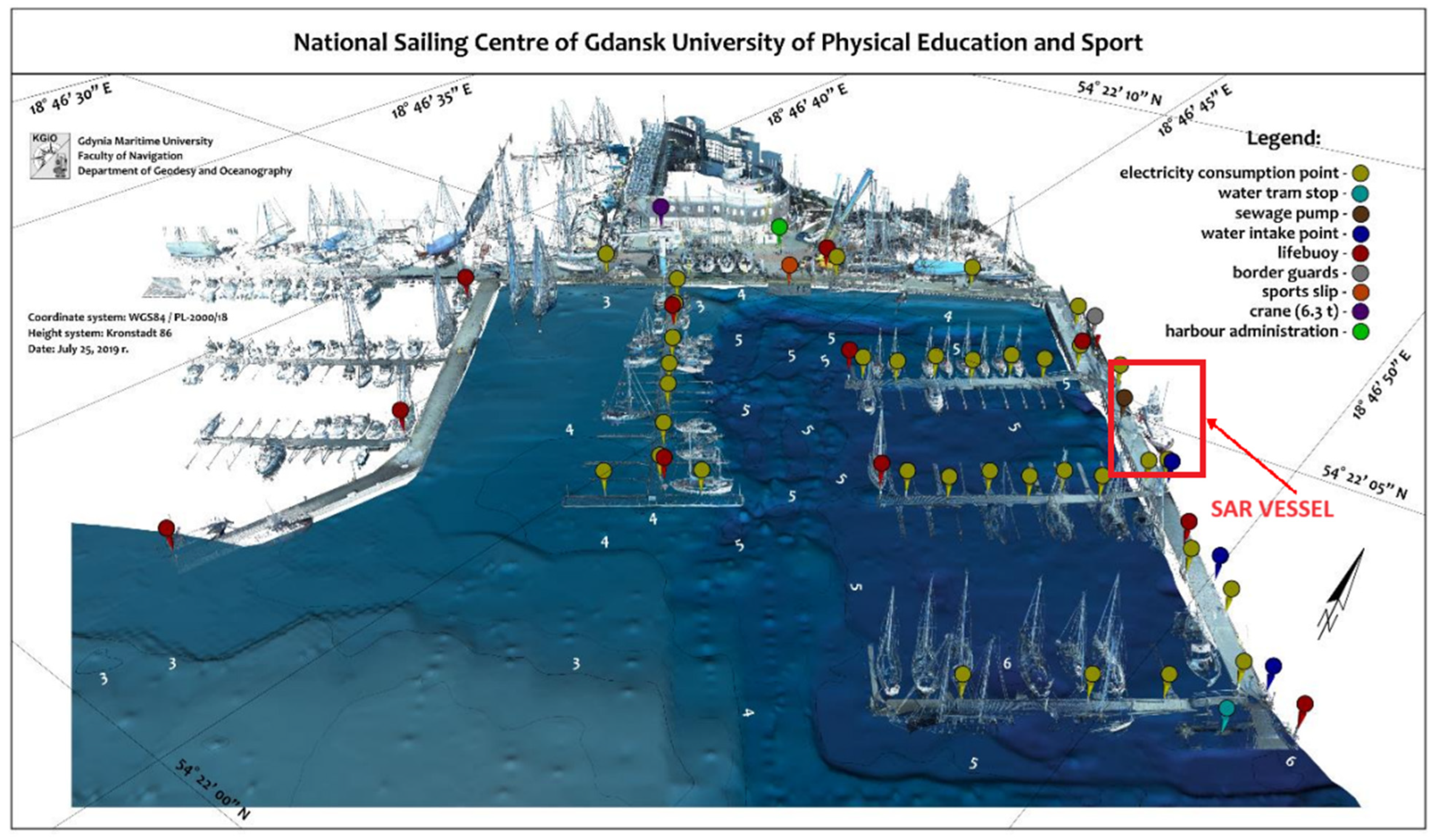
The main area of activity of the NSC is teaching, creating a training place for the Polish team, students from the University of Physical Education and Sport in Gdańsk, as well as young people and children taking part in sailing training. The NSC-GUPES marina consists of 2 port basins. According to the data included in the navigation maps in the ECDIS (Electronic Chart Display and Information System), the depths of the eastern basin range from 3.5 m to 5.9 m, while the western basin is characterised by depths of 3.6 m at the entrance; then, there are shallows up to approximately 2 m. Among the places intended for mooring units, the marina offers a permanent quay and floating piers with berths for approximately 51 units. A SAR unit is moored on the outer side of the port quay [18]. Figure 5 shows the berthing place of the vessel against the background of the harbour.
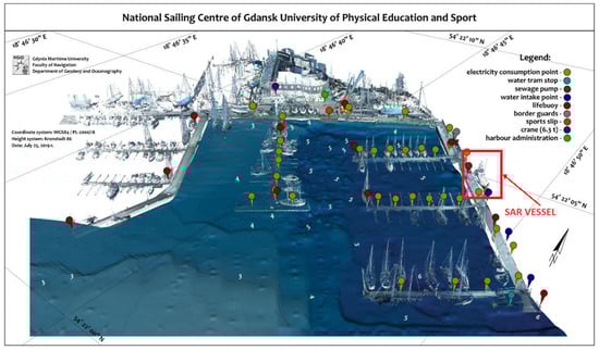
Figure 5.
A thematic map of the National Sailing Centre (NSC) harbour, with the SAR vessel indicated [18].
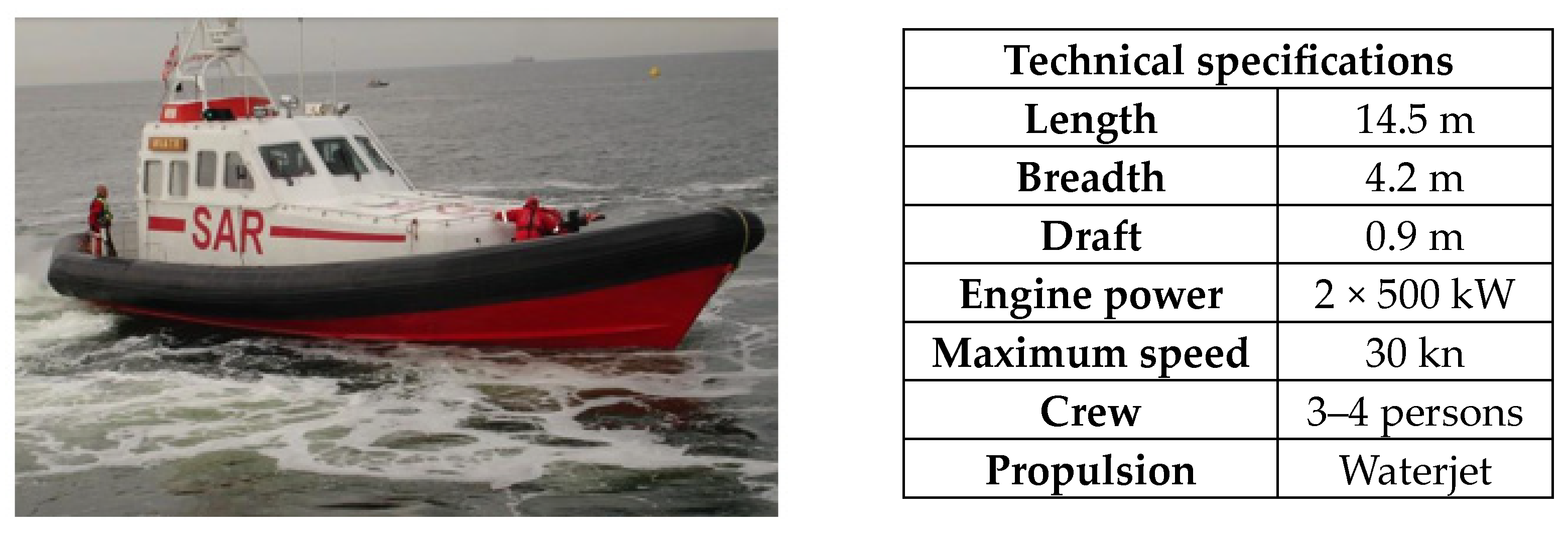
The “SAR-1500”-type vessel, moored at the quay, is characterised by good manoeuvrability and high speed. It is used for searching for survivors, taking them aboard and transporting them ashore; participating in fire-fighting on vessels; and rescue towing [27]. The general characteristics of the SAR Wiatr vessel are presented in Figure 6.
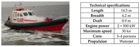
Figure 6.
Technical specifications of the Maritime Search and Rescue Service vessel Wiatr [27].
2.2. Measurement Equipment
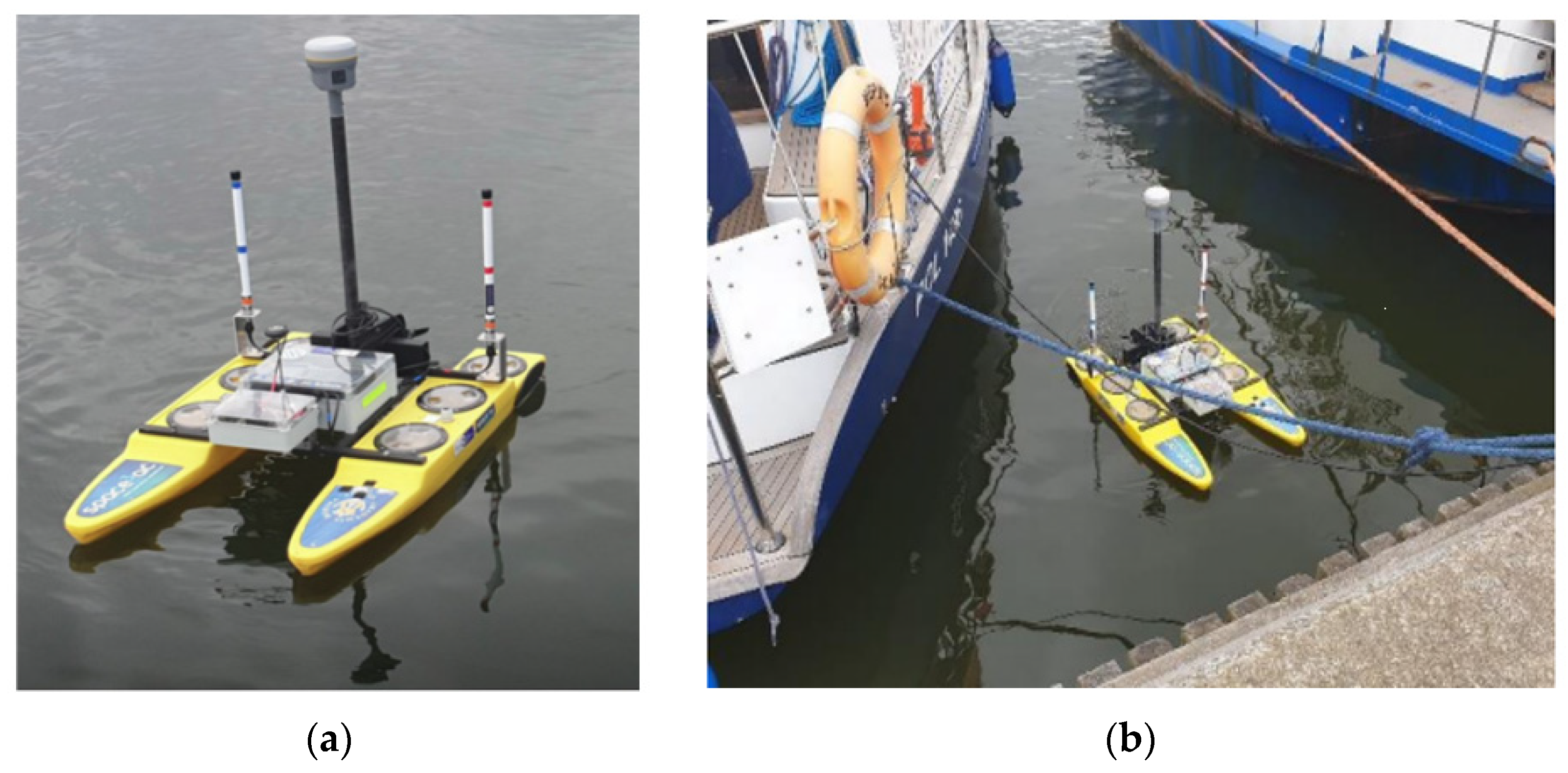
For the purpose of carrying out bottom surveys along the quay of the National Sailing Centre marina, a portable double-hull HyDrone platform (manufactured by Seafloor Systems Inc., El Dorado Hills, CA, USA) for hydrographic applications was utilised. It is characterised by a lightweight, watertight design made of polyethylene, which ensures its resistance to marine environmental conditions and mechanical factors. An aluminium, lightweight and wide profile, joined by a frame, also ensures the stability of the vessel (Figure 7).
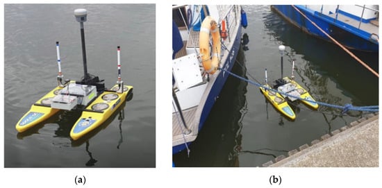
Figure 7.
A HyDrone USV used during surveys (a); a USV taking depth measurements between moored yachts (b) [18,28].
The implementation of surveys is ensured by the equipment and components, which include an autopilot, a navigation receiver with a compass, a GNSS receiver, a vertical echo sounder, integrated propellers, and batteries to extend the vehicle’s operating time. It should be mentioned that the vessel was thoroughly modernised by the department’s team. The basic technical characteristics of a USV, along with its parameters, are provided below (Table 1). The modernisation of the abovementioned components resulted in its operation range being increased by three times, reaching up to 1 km. In comparison to its characteristics before modernization, the replacement of batteries enabled its operating time to be extended by four times, allowing for the working time on one charge of battery to be increased and making work more efficient. An autopilot was installed on it, making it possible to operate in automatic mode, and its power was increased (2 × 50 N). Thanks to the replacement of equipment and components, the USV unit reduced its weight by 28%, which increased its manoeuvrability and made it more compact. During the conducted measurements, the USV was equipped with hydrographic equipment including a hydrographic SonarMite SBES operating at a frequency of f = 200 kHz and a Trimble R10 GNSS (manufactured by Trimble, Westminster, CO, USA) receiver operating at a frequency of 1 Hz in the commercial GNSS network called VRSNet.pl, which is very popular in Poland. To confirm the proper functioning of the sensors on the USV unit and eliminate potential errors, a calibration was carried out. This included measuring the vertical distribution of sound speed in water, measuring the immersion of the echo sounder transducer, and performing the calibration of the inclinometer and magnetometer. Details of the use of the USV in these types of measurements are described in the following publication: [18,28].

Table 1.
The characteristics of a HyDrone hydrographic platform [18].
2.3. Realisation of Measurement and Data Processing
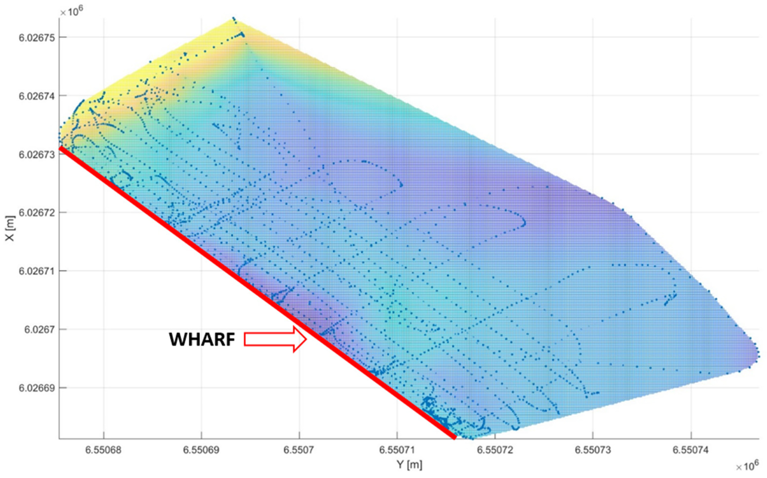
When carrying out bathymetric surveys using a USV, it was decided to control it in a direct manner. Carrying out these surveys in automatic mode would have required survey lines to be prepared in advance. However, the movement of vessels, which cannot be predicted, resulted in the choice of manual control. In addition, as a result of the lack of knowledge of the exact location of deepened areas, control survey lines increasing the density of surveys had to be adjusted to the depth results obtained in real time. The trajectory of an unmanned surface vehicle (USV) along the quay is shown in Figure 8.

Figure 8.
Trajectory of an unmanned surface vehicle along the wharf.
The geodetic coordinates (φ, λ) of the controlled depths obtained during the measurements were converted into plane coordinates (x, y) in the Gauss–Krüger projection, in the PL 2000 coordinate system applicable in Poland, where the functions have the following form [29,30]:
where
- x, y—coordinates in the Gauss–Krüger projection, in the PL 2000 coordinate system applicable in Poland [m];
- φ, λ—geodetic coordinates [°];
- a—6,378,137.000 m—length of the semi-major axis of the WGS–84 ellipsoid;
- e—eccentricity;
- N—radius of curvature perpendicular to the meridian [m];
- M—distance along the meridian from the Equator to latitude φ.
The transformation of geodetic coordinates to the PL 2000 system, which is applicable in Poland, is essential for correctly positioning points on the Earth’s surface to their corresponding locations on a plane map, enabling precise geospatial analysis. This transformation converts spherical coordinates expressed in degrees to plane coordinates represented in metres, while maintaining minimal distortions. The modification involves changing the scale factor from 1 to m0 = 0.999923, where x represents the horizontal position—latitude (north/south direction), and y represents the vertical position—longitude (east/west direction) [30]. For the x coordinate, its value is the distance in metres from the equator, while for the y coordinate, it is the distance from the central meridian in the Gauss–Krüger projection (assigned 500 000 m), with the number 6 being merely the zone number designation (one of four: 5, 6, 7, 8) rather than a numerical value.
3. Results
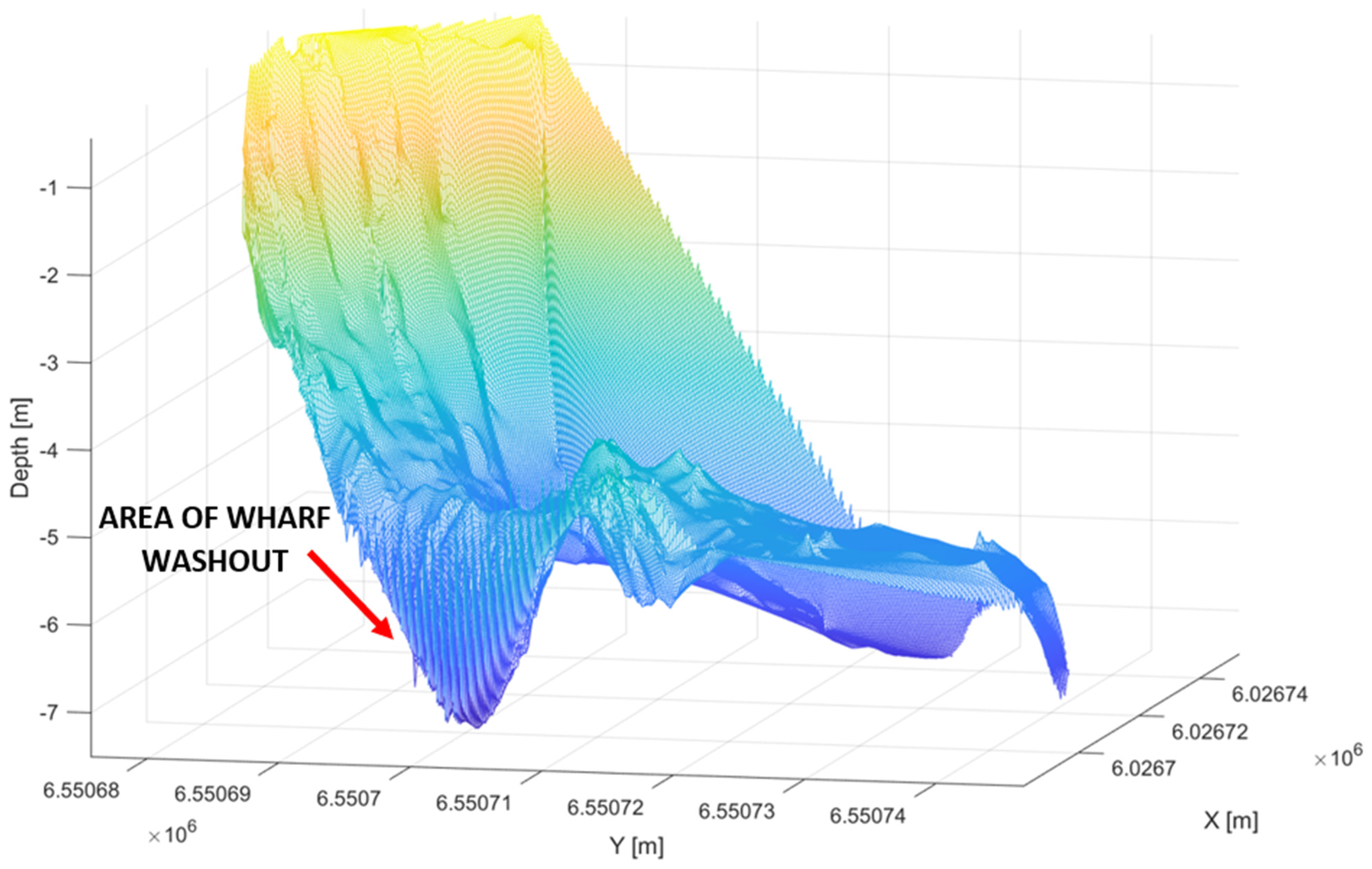
Based on the collected bathymetric data, three-dimensional graphical images of the bottom were produced. To this end, a computer programme representing a simulation development environment, namely MATLAB, version R2021b, was used. The resulting images enable the presentation of the water area bathymetry in a varied manner, thanks to the flexibility of the software, which enables the transparent analysis of the site of a significant drop in depth. A localised drop in depth from 5.5 m to below 7 m was noted at two locations (as a result of the operation of the SAR vessel’s two propellers). Figure 9 shows the deepened area, indicated in purple.
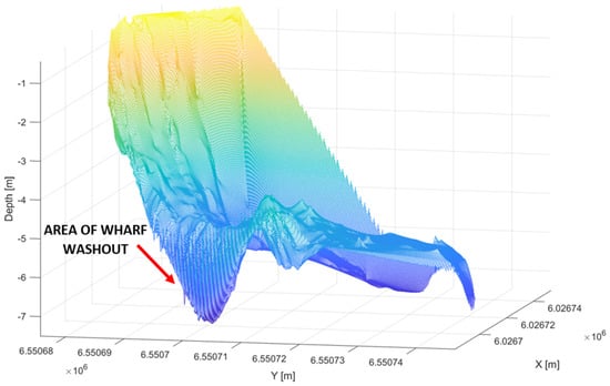
Figure 9.
A model showing the bottom topography along the quay.
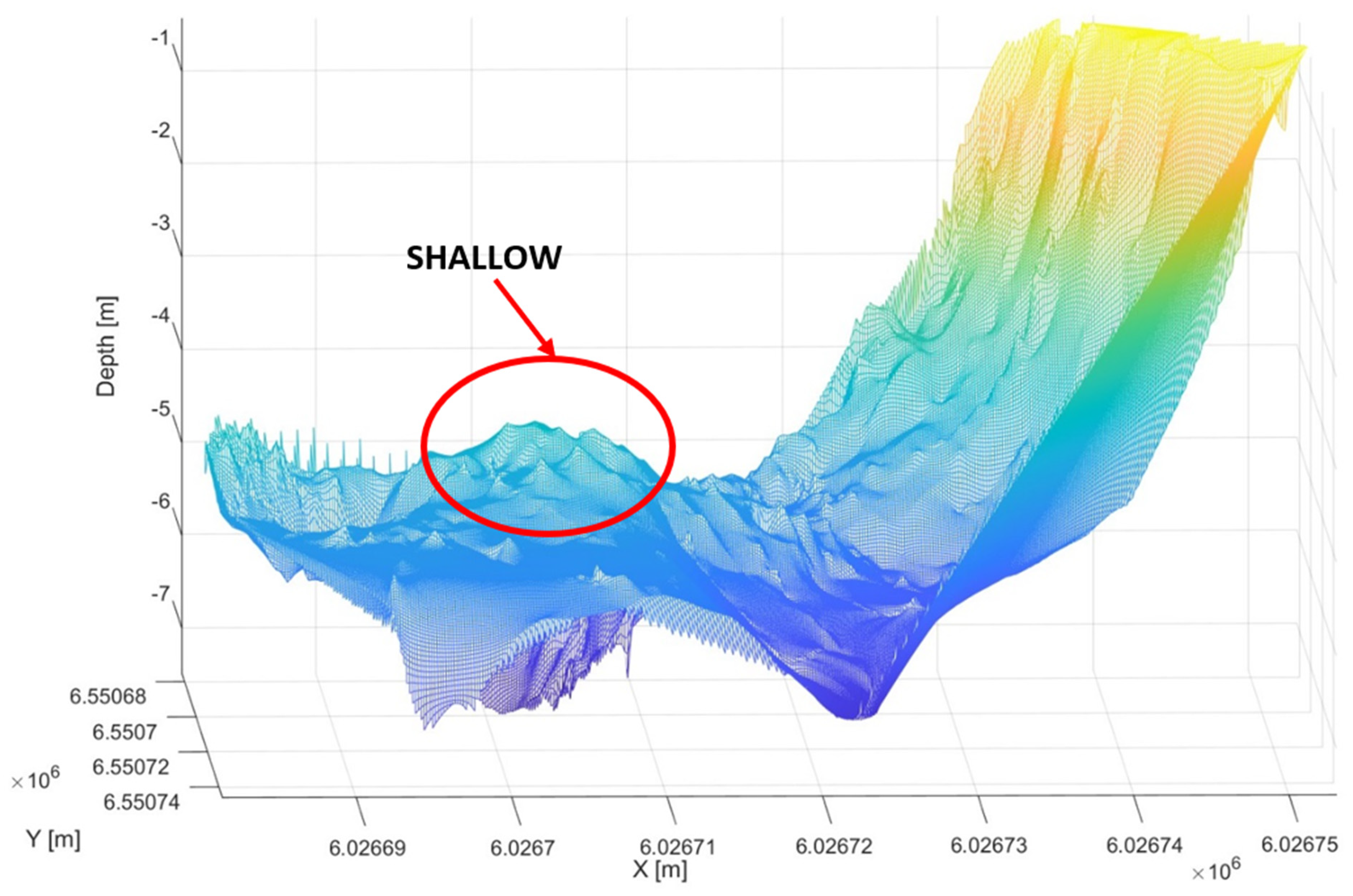
In addition, it was observed that the washed-out bottom material was shifted approx. 10 m away from the quay, resulting in the shallowing of the bottom at two locations from a depth of approx. 5.5 to 4.7 m, which is shown in Figure 10 and Figure 11.

Figure 10.
Seabed topography along the quay—a shallow-water area.
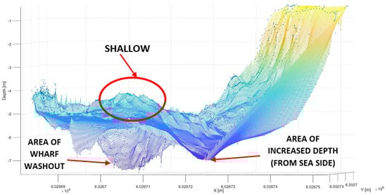
Figure 11.
Bottom topography along the quay with the survey points plotted.
In order to check the provision of an adequate density of survey points (local lack of data) that enable the formation of a surface, Figure 11 is supplemented with survey points.
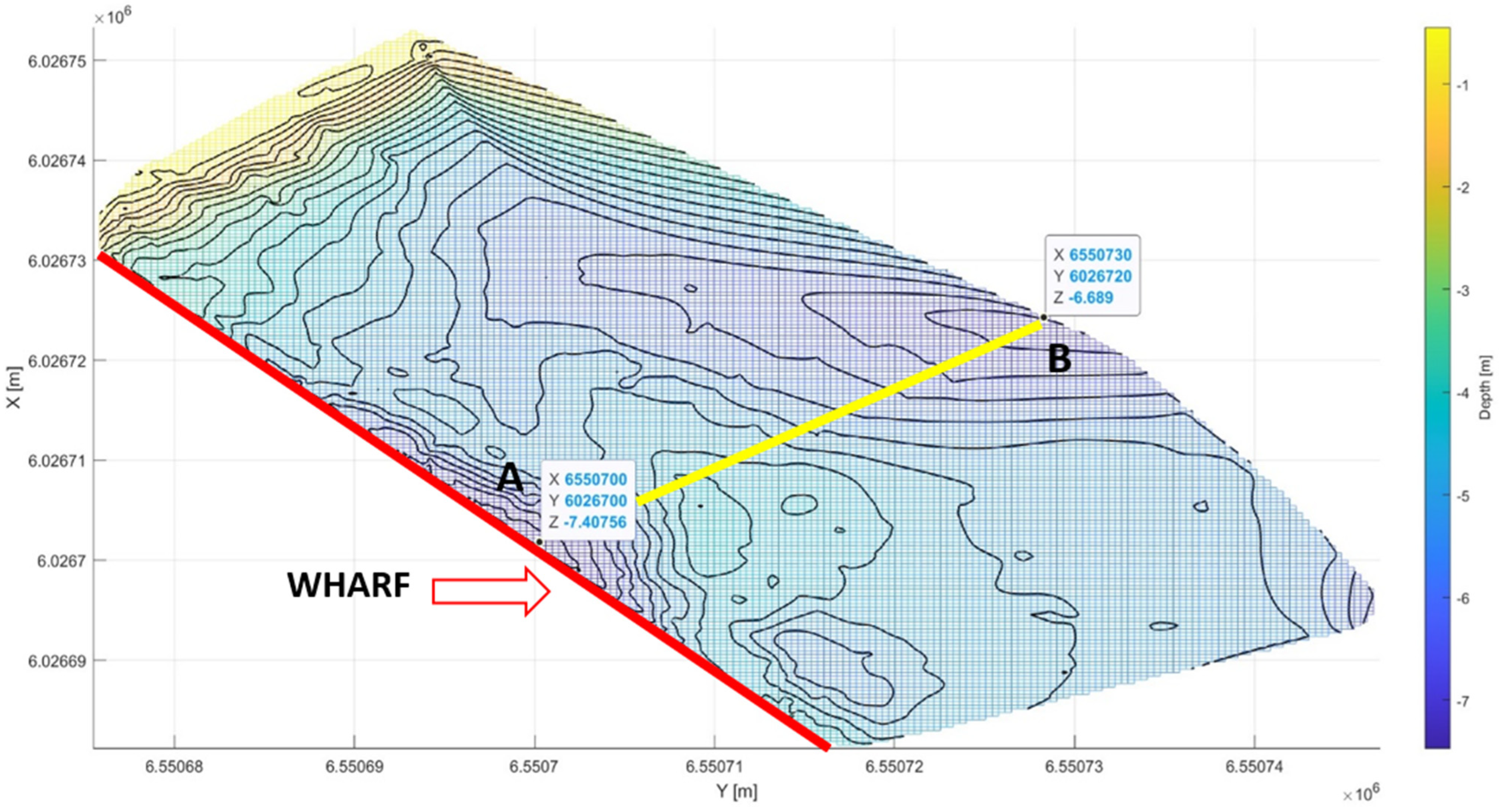
Figure 12 presents a bathymetric map compiled on the basis of collected surveys, along with plotted isobaths showing the varying depths of the water area.
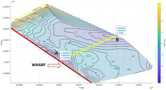
Figure 12.
A bathymetric map of the bottom of the National Sailing Centre of the Gdańsk University of Physical Education and Sport (NSC-GUPES). Two shallow-water areas resulting from the operation of the SAR vessel propeller are marked, and the depth change profile for further analysis is marked in yellow.
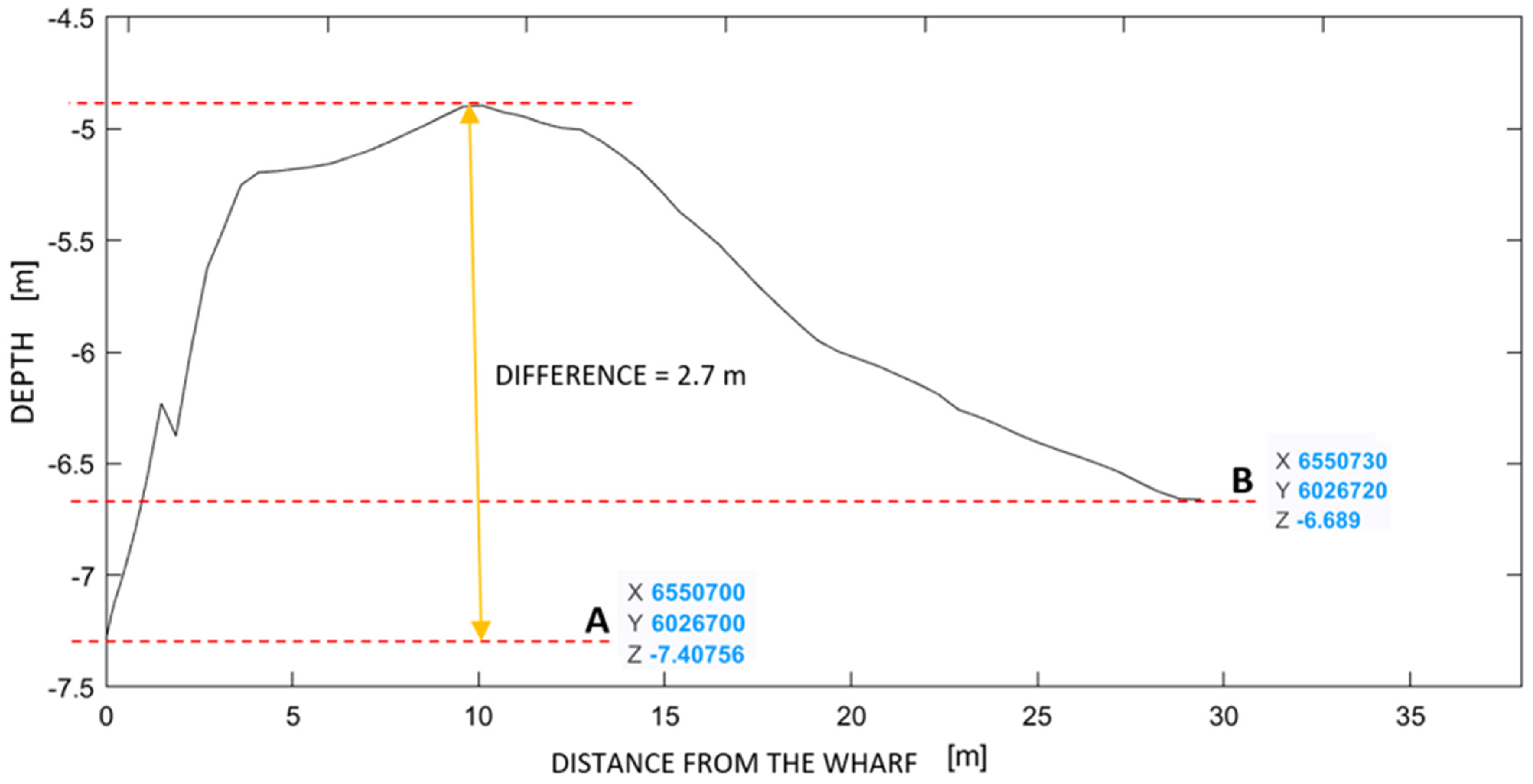
Using the bathymetric data collected with the USV and the produced bottom image simulations, a cross-section of the surface was made along the yellow line between the two points marked A and B. Figure 13 shows the changes in the topography of the bottom under inspection, observed and described in the article, along the direction of the largest depth changes.
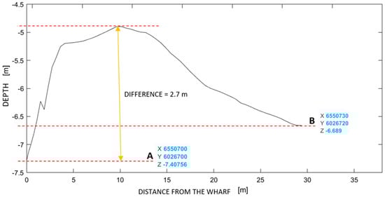
Figure 13.
Diagram of the cross-section through the water area along the quay of the National Sailing Centre (NSC) marina between two points indicating changes in depth, along with the distance from the quay. The analysis was conducted using MATLAB software version R2021b.
4. Discussion
The performed surveys demonstrated that unmanned surface vehicles (USVs) are the optimal tool for carrying out immediate inspections of the seabed. Thanks to their small size, light weight and high control precision, USVs are capable of collecting accurate bathymetric data at any time and in any area.
The solution presented in the article offers an alternative to surveys carried out using typical hydrographic vessels. USVs are particularly suitable for use in areas that are difficult to access, such as marinas, requiring a high degree of mobility. Similar research was conducted by Specht M. et al. [28]. The authors of the article also used the “HyDrone” USV to collect data. The aim of this publication was to respond to the need to prepare bathymetric maps of the NSC-GUPES yacht port. The measurements performed thoroughly covered the area with data on the depths occurring in the marina. The authors compared the obtained data with the data presented on the official ENC maps. The bathymetric maps obtained by the authors provide more accurate data on depth variability, ensuring safety navigation. It should be emphasised that in the available literature (except the publication mentioned above [28]), there is no similar use of USVs for conducting measurements described in this article. The authors considered this approach beneficial compared to using other classical measurement methods for this purpose. The method of seabed bathymetry determination using marine hydrographic LiDAR has limited operational range, as the use of this technology is subject to certain limitations including water clarity, with turbid or polluted water significantly limiting measurement effectiveness; and atmospheric conditions, where laser measurement is affected by factors such as rain, fog, heavy cloud cover or intense sunlight, which can interfere with LiDAR signals, reducing image quality. Additionally, bathymetric LiDAR is a costly technology, which may pose a financial barrier for managers of private facilities or marinas, including the NSC GUPES, yet this does not exempt them from the obligation to control hydrotechnical objects. As an alternative solution, this article proposes the use of USVs for such activities, capable of conducting bathymetric measurements in hard-to-reach places such as narrow channels or shallow waters. Furthermore, compared to traditional hydrographic vessels and technologies, operational costs are significantly lower, and the risk of damaging port infrastructure and other measurement units is minimised. USVs enable more frequent inspections, allowing for the regular monitoring of seabed conditions and rapid responses to changing circumstances. The information and measurement results presented in this article can be helpful for daily marina management and mooring places.
Using MATLAB software, a three-dimensional simulation of the bottom’s bathymetric image, indicating the problems of the area under inspection, was developed. Regular inspections minimise the risk of failure and limit the occurrence of potential damage, such as quay structure damage due to the washout of the bottom.
5. Conclusions
This article presents the use of USVs for carrying out urgent and immediate inspections of the bottom, which ensure the monitoring and maintenance of the technical condition of any water area. The surveys were carried out in the area along the quay of the National Sailing Centre of the Gdańsk University of Physical Education and Sport, where the SAR vessel is regularly moored. The study characterised the survey equipment used and described the course of implementation of the hydrographic surveys using autonomous unmanned vehicles. It also proposed and discussed methods for presenting the results of bathymetric surveys of the shallow-water area. The result of the graphical presentation of the data is a three-dimensional bathymetric map that shows the great variation in the bottom topography along the quay. The presented bathymetric bottom topography model showed the occurrence of the bottom material washed out from it at the location of the operation of the moored SAR vessel engines, thus resulting in the scouring of the quay. If this situation is ignored, the structural stability of the quay may be compromised.
In future research, it would be useful to determine changes occurring over time. Using USV again, it is planned to carry out bathymetric measurements along the quay where the SAR unit regularly moors and then perform their comparative analysis. Moreover, it would be worth determining the impact of the ongoing changes on the structure of the quay and the safety of navigation (formation of shallows), including the continued possibility of mooring the SAR unit in a designated place. It should be noted that the measurements were conducted using direct control. There is no doubt that the development of such measurements should focus on automatic control, considering other control methods as described in another publication [31].
Therefore, it is advisable to take corrective measures. One of the effective and alternative solutions to protect the bottom against washing out and thus the structure of the quay is to use geotextile mattresses. These special protective mats, filled with sand, prevent bottom erosion, which may be caused by strong propeller jets. Preventing bottom erosion means less need for regular deepening of the port, which translates into lower costs of maintaining port infrastructure. However, the use of alternative methods does not make owners exempt from the obligation to carry out regular hydrographic inspections, which are regulated by IHO regulations. Regular inspections, for which small, portable USVs are very well suited, support the detection of areas dangerous to navigation as well as the identification of shallow waters and provide information on the technical condition of the harbour infrastructure.
Author Contributions
Conceptualization, C.S. and D.Ś.; methodology, C.S and D.Ś.; software, C.S. and D.Ś.; validation, C.S. and D.Ś.; formal analysis, C.S.; investigation, C.S.; resources, C.S.; data curation, C.S.; writing—original draft preparation, C.S. and D.Ś.; writing—review and editing, C.S. and D.Ś.; visualization, C.S. and D.Ś.; supervision, C.S.; project administration, C.S.; funding acquisition, C.S. All authors have read and agreed to the published version of the manuscript.
Funding
This research was funded from the statutory activities of Gdynia Maritime University, grant number WN/2024/PZ/05.
Data Availability Statement
The raw data supporting the conclusions of this article will be made available by the authors on reasonable request.
Acknowledgments
The authors would like to thank Oktawia Specht and Mariusz Specht for providing the survey data.
Conflicts of Interest
The authors declare no conflict of interest.
References
- IHO S-44; IHO Standards for Hydrographic Surveys, 6.1.0 ed. IHO: Monte Carlo, Monaco, 2022.
- Canadian Hydrographic Service. CHS Standards for Hydrographic Surveys, 4th ed.; CHS: Ottawa, ON, Canada, 2021. [Google Scholar]
- Stateczny, A.; Grońska, D.; Motyl, W. Hydrodron—New Step for Professional Hydrography for Restricted Waters. In Proceedings of the 2018 Baltic Geodetic Congress, Olsztyn, Poland, 21–23 June 2018. [Google Scholar]
- National Oceanic and Atmospheric Administration. NOS Hydrographic Surveys Specifications and Deliverables; NOAA: Silver Spring, MD, USA, 2017. [Google Scholar]
- Makar, A.; Specht, C.; Specht, M.; Dąbrowski, P.; Szafran, M. Integrated Geodetic and Hydrographic Measurements of the Yacht Port for Nautical Charts and Dynamic Spatial Presentation. Geosciences 2020, 10, 203. [Google Scholar] [CrossRef]
- Suhari, K.T.; Karim, H.; Gunawan, P.H.; Purwanto, H. Small ROV Marine Boat for Bathymetry Surveys of Shallow Waters—Potential Implementation in Malaysia. Int. Arch. Photogramm. Remote Sens. Spat. Inf. Sci. 2017, XLII-4/W5, 201–208. [Google Scholar]
- Giordano, F.; Mattei, G.; Parente, C.; Peluso, F.; Santamaria, R. Integrating Sensors into a Marine Drone for Bathymetric 3D Surveys in Shallow Waters. Sensors 2016, 16, 41. [Google Scholar] [CrossRef] [PubMed]
- Kurowski, M.; Thal, J.; Damerius, R.; Korte, H.; Jeinsch, T. Automated Survey in Very Shallow Water Using an Unmanned Surface Vehicle. IFAC Pap. 2019, 52, 146–151. [Google Scholar] [CrossRef]
- Specht, C.; Weintrit, A.; Specht, M. Determination of the Territorial Sea Baseline—Aspect of Using Unmanned Hydrographic Vessels. TransNav. Int. J. Mar. Navig. Saf. Sea Transp. 2016, 10, 649–654. [Google Scholar] [CrossRef]
- Iwen, D.; Wąż, M. Benefits of using ASV MBES surveys in shallow waters and restricted areas. In Proceedings of the European Navigation Conference (ENC), Warsaw, Poland, 9–12 April 2019. [Google Scholar]
- Stateczny, A.; Kazimierski, W.; Burdziakowski, P.; Motyl, W.; Wisniewska, M. Shore Construction Detection by Automotive Radar for the Needs of Autonomous Surface Vehicle Navigation. ISPRS Int. J. Geo-Inf. 2019, 8, 80. [Google Scholar] [CrossRef]
- Liu, Z.; Zhang, Y.; Yu, X.; Yuan, C. Unmanned Surface Vehicles: An Overview of Developments and Challenges. Annu. Rev. Control 2016, 41, 71–93. [Google Scholar] [CrossRef]
- Romano, A.; Duranti, P. Autonomous Unmanned Surface Vessels for Hydrographic Measurement and Environmental Monitoring. In Proceedings of the FIG Working Week 2012, Rome, Italy, 6–10 May 2012. [Google Scholar]
- Offshore Engineer. Available online: https://www.oedigital.com/news/474800-raising-the-pipeline-inspection-game (accessed on 7 July 2024).
- Stateczny, A.; Kazimierski, W.; Gronska-Sledz, D.; Motyl, W. The Empirical Application of Automotive 3D Radar Sensor for Target Detection for an Autonomous Surface Vehicle’s Navigation. Remote Sens. 2019, 11, 1156. [Google Scholar] [CrossRef]
- Kasvi, A.; Salmela, J.; Lotsari, E.; Kumpula, T.; Lane, S.N. Comparison of Remote Sensing Based Approaches for Mapping Bathymetry of Shallow, Clear Water Rivers. Geomorphology 2019, 33, 180–197. [Google Scholar] [CrossRef]
- Stateczny, A.; Burdziakowski, P.; Najdecka, K.; Domagalska-Stateczna, B. Accuracy of Trajectory Tracking Based on Nonlinear Guidance Logic for Hydrographic Unmanned Surface Vessels. Sensors 2020, 20, 832. [Google Scholar] [CrossRef] [PubMed]
- Specht, C.; Makar, A.; Specht, M.; Dąbrowski, P.; Cywiński, P. Bathymetric Charts of the Yacht Port National Sailing Centre the Gdańsk University of Physical Education and Sport; Technical Report; Gdynia Maritime University: Gdynia, Poland, 2020. [Google Scholar]
- Specht, M.; Specht, C.; Lasota, H.; Cywiński, P. Assessment of the Steering Precision of a Hydrographic Unmanned Surface Vessel (USV) along Sounding Profiles Using a Low-cost Multi-Global Navigation Satellite System (GNSS) Receiver Supported Autopilot. Sensors 2019, 19, 3939. [Google Scholar] [CrossRef] [PubMed]
- Specht, M.; Stateczny, A.; Specht, C.; Widźgowski, S.; Lewicka, O.; Wiśniewska, M. Concept of an Innovative Autonomous Unmanned System for Bathymetric Monitoring of Shallow Waterbodies (INNOBAT System). Energies 2021, 14, 5370. [Google Scholar] [CrossRef]
- Marchel, Ł.; Specht, C.; Specht, M. Assessment of the Steering Precision of a Hydrographic USV along Sounding Profiles Using a High-Precision GNSS RTK Receiver Supported Autopilot. Energies 2020, 13, 5637. [Google Scholar] [CrossRef]
- Abramowicz-Gerigk, T.; Gerigk, M.K.; Hapke, L.; Tetfejer, K. Cloud-based system for monitoring loads generated on the quay wall by ship propeller jets. Mar. Struct. 2024, 93, 103517. [Google Scholar] [CrossRef]
- Giordano, F.; Mattei, G.; Parente, C.; Peluso, F.; Santamaria, R. MicroVEGA (Micro Vessel for Geodetics Application): A Marine Drone for the Acquisition of Bathymetric Data for GIS Applications. Int. Arch. Photogramm. Remote Sens. Spat. Inf. Sci. 2015, XL-5/W5, 123–130. [Google Scholar]
- Misztal, K. Organization and Operation of Seaports, 1st ed.; University of Gdańsk: Gdańsk, Poland, 2010. (In Polish) [Google Scholar]
- Abramowicz-Gerigk, T.; Burciu, Z. Assessment of the Condition of the Bottom Reinforcement System in the Area of Port Quays, Maintenance Problems No. 1; Akademia Morska w Gdyni: Gdynia, Poland, 2011; pp. 7–16. (In Polish) [Google Scholar]
- Magda, W. Marine Construction. Selected Issues with Calculation Examples; PWN Publishing House: Warsaw, Poland, 2022. (In Polish) [Google Scholar]
- SAR. Available online: https://www.sar.gov.pl/pl/equipment/sar1500/ (accessed on 21 May 2024).
- Specht, M.; Specht, C.; Szafran, M.; Makar, A.; Dąbrowski, P.; Lasota, H.; Cywiński, P. The Use of USV to Develop Navigational and Bathymetric Charts of Yacht Ports on the Example of National Sailing Centre in Gdańsk. Remote Sens. 2020, 12, 2585. [Google Scholar] [CrossRef]
- Snyder, J.P. Map Projections—A Working Manual; US Government Printing Office: Washington, DC, USA, 1987; Volume 1395. [Google Scholar]
- Dabrowski, P.S.; Specht, C.; Specht, M.; Makar, A. Three-Dimensional Thematic Map Imaging of the Yacht Port on the Example of the Polish National Sailing Centre Marina in Gdańsk. Appl. Sci. 2021, 11, 7016. [Google Scholar] [CrossRef]
- Cui, S.; Chen, Y.; Li, X. A Robust and Efficient UAV Path Planning Approach for Tracking Agile Targets in Complex Environments. Machines 2022, 10, 931. [Google Scholar] [CrossRef]


Disclaimer/Publisher’s Note: The statements, opinions and data contained in all publications are solely those of the individual author(s) and contributor(s) and not of MDPI and/or the editor(s). MDPI and/or the editor(s) disclaim responsibility for any injury to people or property resulting from any ideas, methods, instructions or products referred to in the content. |
© 2024 by the authors. Licensee MDPI, Basel, Switzerland. This article is an open access article distributed under the terms and conditions of the Creative Commons Attribution (CC BY) license (https://creativecommons.org/licenses/by/4.0/).