Article

A New Angle-Calibration Method for Precise Ultra-Short Baseline Underwater Positioning

1
College of Oceanography and Space Informatics, China University of Petroleum (East China), Qingdao 266580, China
2
College of Intelligent Systems Science and Engineering, Harbin Engineering University, Harbin 150001, China
3
China Geological Survey Qingdao Institute of Marine Geology, Qingdao 266580, China
*
Author to whom correspondence should be addressed.
Remote Sens. 2024, 16(14), 2584; https://doi.org/10.3390/rs16142584
Submission received: 14 May 2024 / Revised: 2 July 2024 / Accepted: 12 July 2024 / Published: 14 July 2024

Abstract

:
Ultra-short baseline (USBL) underwater positioning systems are widely used in marine scientific research and ocean engineering. Angle misalignment is a main error that reduces the accuracy of USBL underwater positioning. The conventional angle-calibration method assumes that the transponder position obtained by USBL positioning is an errorless coefficient matrix. However, errors inevitably exist in the estimation of the transponder’s position via USBL positioning, and the precision varies at different epochs. Ignoring the error in the transponder’s position will significantly reduce the precision of the angle misalignment estimation. In this paper, a new angle-calibration method is proposed for precise USBL underwater positioning. The angle alignment model is derived by treating the transponder’s position obtained by USBL positioning as an observation, and the stochastic model is then established according to the bearing angles. Robust estimation is likewise applied to further improve the precision of the angle misalignment estimation. To verify the performance of the proposed method, a sea experiment was performed. The results show that the new method has high calibration accuracy and robustness. The estimation precision of this method is improved by 0.0457°~0.6896° in heading, 0.0125°~0.8072° in roll, and 0.0077°~0.9436° in pitch, compared with that of the conventional angle alignment method.

1. Introduction

The ultra-short baseline (USBL) underwater positioning technique was pioneered by Roberts at the seventh annual offshore technology conference in Houston, USA [1]. It can precisely determine the position of the target transponder by adopting acoustic ranging and bearing angles in conjunction with the position, attitude, and heading of a sea surface platform [2,3,4]. In recent decades, this technique has been widely applied in various fields, including underwater navigation and positioning [5,6,7,8,9,10,11,12], seismic deformation acquisition [13], and marine exploration [14,15].
The entire USBL underwater positioning system comprises two parts. One is to determine the position of the target transponder in the acoustic reference framework using acoustic ranging and bearing angles [2,3,4,16]. The acoustic reference framework is a local coordinate system specific to USBL underwater positioning [16]. The other is to obtain the position of the target transponder in the navigation reference framework according to the relative relationship between the Global Navigation Satellite System (GNSS) antenna and the USBL transducer [17,18]. However, there are inevitable installation errors between the research vessel and the USBL [7,18,19]. The installation errors consist of the position error between the centre of the GNSS antenna and the USBL transducer and the angle misalignment error between the research vessel and the USBL [18,19]. The position error can be accurately measured by optical measurement methods, while the angle misalignment error cannot be directly measured. Ignoring the angle misalignment error will significantly reduce the accuracy of USBL underwater positioning. For example, an angle misalignment error of 1° can generate an error of at least 1.7% in slant distance [14].
Recently, various angle alignment methods have been implemented in underwater USBL data processing. For example, Cuie applied the least-squares method to calculate the rotation matrix formed by three misalignment angles [20]. Guo proposed an iterative least-squares method for angle misalignment estimation based on a Taylor expansion [21]. Sun proposed a stepwise estimation algorithm that decomposes the rotation matrix into three independent least-squares problems and performs iterative estimation on each component separately [22,23]. These conventional methods generally assume that the position of the seafloor transponder provided by USBL positioning is considered a coefficient matrix without error. However, errors inevitably exist in the estimation of the transponder’s position via USBL underwater positioning, and the precision varies among epochs. Moreover, GNSS positioning and GNSS/acoustic (GNSS/A) underwater positioning can provide positioning accuracies of decimetres or even centimetres in applications [24,25,26], while the USBL method provides positioning accuracies of only metres [2,3]. Consequently, the precision of the observations derived from GNSS positioning and GNSS/A underwater positioning is better than that of the coefficient matrix in the angle alignment model. Ignoring the errors in seafloor transponder coordinates will reduce the precision of angle misalignment estimation, especially when there are outliers in seafloor transponder coordinates. Thus, a more reasonable adjustment method is needed to improve the accuracy of angle misalignment estimation.
In this paper, we propose a new angle alignment method that addresses the errors in seafloor transponder coordinates provided by USBL positioning, achieving precise angle misalignment estimation. Our primary contributions can be summarized as follows:
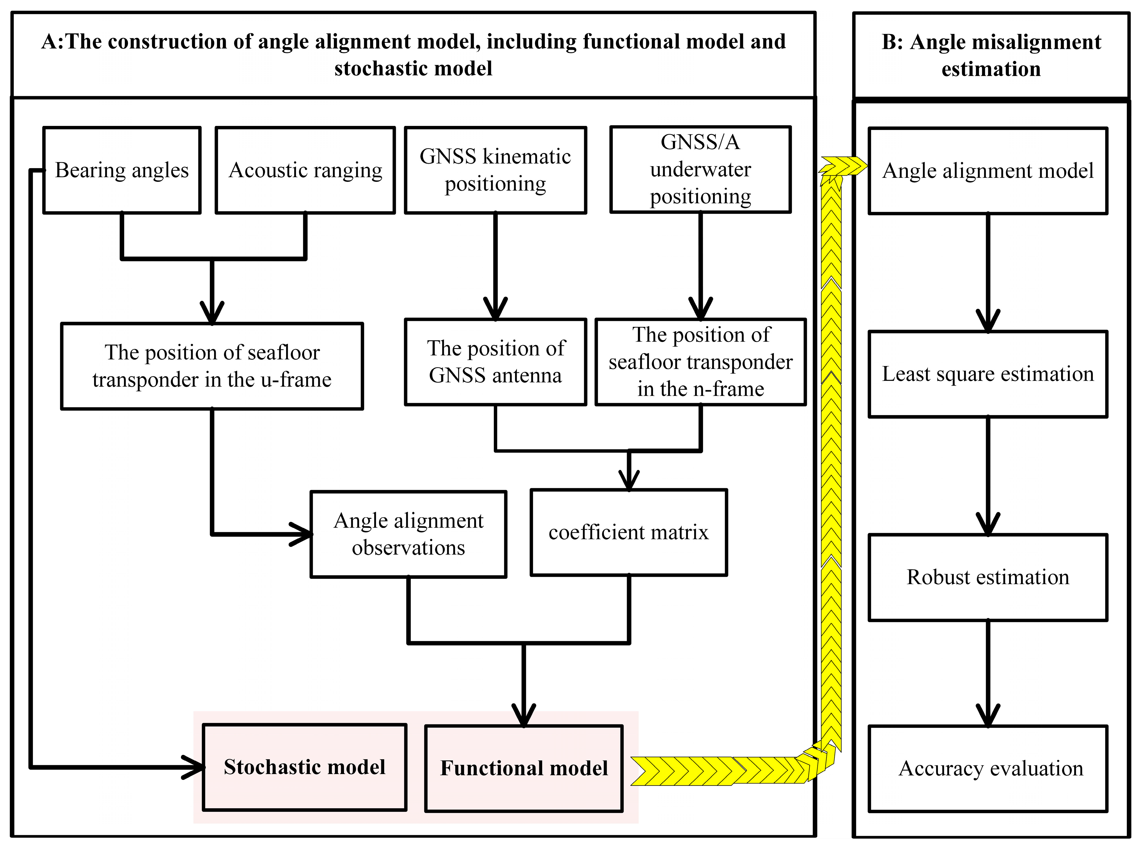
  • We derive a new angle alignment function model by treating the transponder’s position provided by USBL positioning as an observation. The corresponding stochastic model is established according to the bearing angles between the acoustic transducer and the target transponder.
  • To further improve the precision of the angle alignment estimation, we introduce a robust estimation method to mitigate the influence of outliers on the observations.
  • The field results demonstrate that the proposed method improves the accuracy and reliability of angle alignment estimation compared to the conventional angle alignment method, thereby enhancing the precision of USBL underwater positioning.
This paper is organized as follows. In Section 2, the conventional alignment method is briefly introduced. In Section 3, the proposed angle alignment method is presented in detail, including the function model and the stochastic model. In Section 4, field data obtained from South China are collected to validate the effectiveness of the proposed method. Finally, conclusions are drawn in the Section 6.

2. Conventional Alignment Method for USBL Underwater Positioning

The USBL alignment experiment is usually performed by a research vessel sailing around a seafloor transponder, as shown in Figure 1. The coordinate reference frameworks used in angle misalignment estimation for USBL underwater positioning [8,14,15], including the navigation reference framework, the carrier reference framework, and the acoustic reference framework, are introduced. The navigation reference framework ( O n X n Y n Z n , n-frame) aligns with the east–north–up in the geographical coordinate system. The carrier reference framework ( O b X b Y b Z b , b-frame) serves as the coordinate reference system for the research vessel. The X-axis points to the starboard, the Y-axis points to the bow of the research vessel, and the Z-axis is perpendicular to the deck plane and points upwards, forming a right-handed coordinate system. The acoustic reference framework ( O u X u Y u Z u , u-frame) is a local coordinate system specific to USBL underwater positioning, in which the X-axis points to the starboard, the Y-axis points forwards, and the Z-axis points upwards, forming a right-handed coordinate system.

2.1. USBL Underwater Positioning

The USBL underwater positioning system comprises an emitting transducer, four receiving hydrophones arranged in two orthogonal directions, and a seafloor transponder. The onboard transducer continuously broadcasts acoustic signals at a certain frequency to the seafloor transponder and records the propagation time of arrival while receiving the feedback signal from the seafloor transponder [2,3]. The propagation time is transformed into the acoustic range by the field-measured sound velocity profile according to the acoustic ray-tracing method [17]. The four-hydrophone planar array is mainly used to capture the response signals emitted by seafloor transponders and then estimate the time delay between hydrophone pairs in each orthogonal direction [27,28]. Time delay estimation is used to determine the bearing angle between the acoustic transducer and the seafloor transponder [29,30]. With acoustic ranging and bearing angles, the position of the seafloor transponder in the u-frame can be obtained:
x = R cos θ x y = R cos θ y                             z = R 2 x 2 y 2
where R = c t is the acoustic range; c is the sound velocity; t is the one-way observation time; and θ x and θ y are the bearing angles of the seafloor transponder relative to the X- and Y-axes, respectively.
The seafloor transponder position obtained by USBL underwater positioning is a relative position. To obtain the absolute position of the seafloor transponder, a coordinate transform is needed. According to the relative relationship between the n-frame and b-frame, the absolute position of the seafloor transponder can be determined:
T n = P n + R b n R u b T u + X
where T n is the position of the seafloor transponder in the n-frame; P n is the position of the GNSS antenna provided by GNSS kinematic positioning [24]; T u = [ x y z ] T is the position of the seafloor transponder obtained by USBL underwater positioning; R b n is the coordinate transformation matrix between the n-frame and the b-frame, as measured by the motion sensor; X = [ X Y Z ] T is the position error between the centre of the GNSS antenna and the USBL transducer, which can be measured by optical measurement methods; and R u b is the angle misalignment error matrix caused by inconsistencies between the u-frame and the b-frame during USBL installation; that is,
R u b = c α c γ s α s β s γ s α c β c α s γ + s α s β c γ s α c γ + c α s β s γ c α c β s α s γ c α s β c γ c β s γ s β c β c γ
where c · is the cosine operator; s · represents the sine operator; and α , β , and γ are the heading misalignment error, roll misalignment error, and pitch misalignment error, respectively, as shown in Figure 2. Heading misalignment errors primarily affect the accuracy of USBL positioning in the X and Y directions, with minimal influence on the Z direction. Roll misalignment errors mainly affect the accuracy of USBL underwater positioning in the Y and Z directions, while pitch misalignment errors chiefly affect the positioning accuracy in the X and Z directions. Ignoring the angle misalignment errors will considerably reduce the accuracy of USBL underwater positioning. Therefore, a reliable angle alignment method is needed for USBL underwater positioning in practice.

2.2. Conventional Angle Alignment Method

The GNSS/A underwater positioning technique is an active sonar positioning method that uses request–response signals to accurately determine the position of seafloor transponders [31,32]. Assuming that the position of the transponder in the n-frame has been determined by the GNSS/A underwater positioning technique before USBL calibration, the conventional angle alignment equation can be derived from Equation (2) and is denoted as follows:
d = T u T R b u + ε d
where d = T n P n T R b n X T is the observation vector; R b u α is the nonlinear function of angle misalignment errors, including the heading misalignment error, the roll misalignment error, and the pitch misalignment error; α = [ α β γ ] T is the angle misalignment error vector to be estimated; and ε L is the observation error vector.
Treating the positioning of the seafloor transponder provided by USBL positioning as a coefficient matrix without error, the angle alignment equation is linearised as
l = e d α + ε l
where l = d f α 0 ; e = T u T A is the coefficient matrix with a size of 1 × 3; and A is the Jacobian matrix of the nonlinear function R b u with a size of 3 × 3, namely,
A = c α 0 c γ 0 s α 0 s β 0 s γ 0 s α 0 c γ 0 + c α 0 s β 0 s γ 0 c β 0 s γ 0 s α 0 c β 0 c α 0 c β 0   s β 0 c α 0 s γ 0 + s α 0 s β 0 c γ 0 s α 0 s γ 0 c α 0 s β 0 c γ 0 c β 0 c γ 0
where α 0 = [ α 0 β 0 γ 0 ] T is the initial vector of angle misalignment error. With n observations used to estimate the angle misalignment error, the linearized observation equations are re-expressed as
L = J ( α ) d α + ε
where L = [ l 1 l 2 l n ] T is the observation vector with a size of 3n; J α = [ e 1 e 2 e n ] is the coefficient matrix with a size of n × 3; and ε is the error vector with a size of 3n. Based on the least-squares adjustment method, the correction vector of the angle misalignment estimation is
d α ^ = J ( α ) T P J ( α ) 1 J ( α ) T P L
where P is the weight matrix of the angle alignment observations, indicating the precision of the angle alignment observations derived from GNSS positioning and GNSS/A underwater positioning. The angle misalignment estimation is calculated as follows:
α ^ = α 0 + d α ^
The conventional angle alignment method generally treats the position of seafloor transponders obtained by USBL underwater positioning as a coefficient matrix without error. However, errors inevitably exist in the estimation of the transponder position via USBL underwater positioning, and the precision varies among epochs. Moreover, GNSS positioning and GNSS/A underwater positioning can provide positioning accuracies of decimetres or even centimetres in applications [24,25,26], while USBL provides positioning accuracies of only metres [2,3]. Consequently, the accuracy of the coefficient matrix obtained by USBL underwater positioning is lower than that of the angle alignment observations derived from GNSS positioning and GNSS/A underwater positioning. Ignoring the errors of seafloor transponder coordinates will reduce the precision of angle misalignment estimation, particularly in cases where there are outliers in the seafloor transponder coordinates. Thus, a more reasonable adjustment method is needed to improve the accuracy of angle misalignment estimation.

3. Methodology

To improve the accuracy of angle misalignment estimation, this paper proposes a new angle-calibration method for precise USBL underwater positioning, and this approach is discussed in detail.

3.1. Functional Model of the New Angle-Calibration Method

In contrast to the conventional alignment equation, the new angle-calibration method treats the position of the seafloor transponder, obtained by USBL underwater positioning, as the observations, and it can be expressed as
T u = f ( α ) + ε u
where f α = R b u d is the nonlinear function of the angle misalignment error; d is the position deviation between the GNSS antenna and the seafloor transponder in the b-frame; and ε u represents the error vector. Treating the angle misalignment errors as unknown parameters in the new angle alignment equation, as shown in Figure 3A, the new angle alignment equation is linearised as
l ~ = e ( α ) d α + ε l ~
where l ~ = T u f ( α 0 ) ; f α 0 = R b u ( α 0 ) d ; and e ( α ) = A d is the coefficient matrix with a size of 1 × 3.
With n observations obtained by USBL underwater positioning used to estimate the angle misalignment, the linearised observation equations are re-expressed as
L ~ = J ~ ( α ) d α + ε ~
where L ~ = [ l ~ 1 l ~ 2 l ~ n ] T is the new angle alignment observation with a size of 3 n ; J ~ ( α ) = [ e 1 e 2 e n ] is the coefficient matrix with a size of n × 3 ; and ε ~ is the error vector with a size of 3 n . Based on the least-squares adjustment method, the correction vector of the angle misalignment estimation is
d α ^ = J ~ ( α ) T P ~ J ~ ( α ) 1 J ~ ( α ) T P ~ L ~
where P ~ is the weight matrix of the angle alignment observations, which is called the stochastic model. Combining Equation (9) with Equation (13), we can obtain the angle misalignment estimation. Correspondingly, the variance–covariance matrix of the angle misalignment estimation is
D x ^ r = σ ^ 0 2 Q x ^ r σ ^ 0 2 = V T P ~ V n u
where D x ^ r is the variance–covariance matrix of the angle misalignment estimation; σ ^ 0 2 is the a posteriori variance of the unit weight; Q x ^ r = ( J ~ ( α ) T P ~ J ~ ( α ) ) 1 is the cofactor matrix of the angle misalignment estimation; u = 3 ; and V is the residual vector; that is,
V = L ~ J ~ ( α ) d α = ( E n J ~ α J ~ α T P ~ J ~ α 1 J ~ α T P ~ ) L ~
where E n is the unit weight with a size of n × n ; n is the number of observations; and u = 3 is the number of unknown parameters.

3.2. Stochastic Model of the New Angle-Calibration Method

As shown in Equations (13) and (14), the precision of the angle misalignment estimation is influenced by the stochastic model. The stochastic model is mainly used to describe the precision of angle alignment observations obtained by USBL positioning, and the precision varies among epochs. A more precise observation should be assigned a larger weight (or lower variance) and have a greater impact on the angle misalignment estimation. Only an accurate and reliable stochastic model can be used to obtain the optimal angle misalignment estimation and achieve precise USBL underwater positioning. As shown in Equation (1), the variations in bearing angles are closely linked to the precision of USBL underwater positioning. In other words, the bearing angles can reflect the precision of angle alignment observations obtained by USBL underwater positioning. In the horizontal direction, higher bearing angles correspond to increased USBL accuracy; in the vertical direction, they correspond to decreased USBL accuracy [2,30]. The accuracy of the angle alignment observations decreases with decreasing USBL accuracy. Based on this assumption, the bearing angles in three directions can be used to shape the stochastic model, which is expressed as
σ i 2 = σ 0 2 sin θ x i   sin θ y i cos θ z i    
where θ z is the bearing angle of the transponder relative to the Z-axis in the u-frame. The bearing angles in the horizontal direction can be obtained via time delay estimation in USBL signal processing. By applying the cosine theorem, the bearing angle in the vertical direction can be obtained:
cos θ z = 1 cos 2 θ x cos 2 θ y
Ignoring temporal and spatial correlations, the variance in the angle alignment observations is represented as
D L ~ = σ 1 2 0 0 0 σ 2 2 0 0 0 0 0 0 σ n 2
Correspondingly, the stochastic model of angle alignment observations is constructed as follows:
P ~ = σ 0 2 D L ~ 1
After refining the stochastic model, the angle misalignment estimation can be obtained by using Equation (13). However, there are inevitably outliers for the angle alignment observations obtained by USBL underwater positioning. These outliers considerably reduce the accuracy of angle misalignment estimation. To control for the influence of outliers, robust methods have been developed for geodetic data processing [33,34]. Robust estimation can be applied to the new alignment method to handle gross errors in observations. Thus, the commonly used IGGIII equivalent weight [35] is introduced to eliminate the outliers in the observations:
p i = p ~ i f ( v i )
where p ~ i is the ith diagonal element of the bearing angle weight matrix P ~ ; v i is the ith element of the residual vector V ; and f ( v i ) is the IGGIII weight function; that is,
f ( v i ) = 1 v ~ i k 1               k 1 v ~ i k 2 v ~ i k 2 k 1 k 1 < v ~ i k 2 0 k 2 < v ~ i
where k 1 = 1.5 ; k 2 = 3.0 ; and v ~ i are the standardized residuals; that is,
v ~ i = v i σ ^ p                       σ ^ p = 1.483 × m e d   [ a b s v 1 , a b s v n ]
where m e d ( · ) is the median operator. By applying the IGGIII equivalent weight (20) to (13), as shown in Figure 3B, the angle misalignment estimation can be re-estimated.

4. Results and Analysis

To verify the effectiveness of the proposed method, a USBL calibration experiment was performed in the South China Sea on 6 April 2021. The scientific research vessel “Marine Geology No. 9” of China was equipped with the Veripos APEX differential GNSS receiver, a 102PMGC USBL underwater positioning system, and a motion sensor from the HiPap 102PMGC device. The vessel measures 87.07 m in length and 17 m in width and has a depth of 7.8 m. A transponder, fixed by a shelter, was placed on the seafloor. The major instruments used are presented in Figure 4. Interrogation signals were transmitted simultaneously from the acoustic transducer and received by the seafloor transponder. The seafloor transponder, located at approximately 115 m, was measured by the GNSS/A underwater positioning technique. The position of the GNSS antenna was obtained via the GNSS kinematic technique. The horizontal positioning was better than ±0.10 m, and the vertical positioning was better than ± 0.15 m. The motion sensor of the HiPap 102PMGC device was used to measure the real-time attitude and heading of the scientific research vessel, with an attitude accuracy better than 0.01° and a heading accuracy over 0.025°. The sound velocity structure was measured by a sound velocity profiler, and its average sound speed was 1489.7 m/s. The position of the seafloor transponder in the U-frame was provided by USBL underwater positioning, and its precision was better than 0.25%R. Six datasets, each comprising 200 points, were collected independently, as shown in Figure 5. The data sampling frequency was 0.2 Hz.
The bearing angles between the acoustic transducer and the seafloor transponder in three directions are shown in Figure 6. The bearing angles exhibit considerable variation across datasets. This attribute indicates that the precision of USBL underwater positioning varies at different epochs. The static results of the bearing angles for USBL underwater positioning are shown in Table 1. For datasets 1 to 6, the bearing angles have average values of 47.22°, 55.38°, 44.28°, 55.14°, 57.29°, and 57.21° in the X direction, respectively, and the maximum bearing angle is observed in dataset 5. For datasets 1 to 6, the bearing angles have average values of 52.53°, 42.00°, 56.71°, 47.93°, 56.64°, and 57.22° in the Y direction, respectively, and 39.70°, 41.63°, 37.27°, 35.03°, 8.55°, and 4.23° in the Z direction, respectively. The variations in the bearing angles are directly related to the precision of USBL positioning. In the horizontal direction, higher bearing angles correspond to increased USBL accuracy; in the vertical direction, they correspond to decreased USBL accuracy. Thus, the precision of USBL underwater positioning should be considered during USBL calibration.
The conventional and new angle-calibration methods were used to conduct angle misalignment estimation. The statistical results are shown in Table 2. To assess the effectiveness of the proposed method, angle misalignment estimations obtained from the postprocessing software APOS version 6 provided by the Kongsberg Company were used as a reference. The angle misalignment estimation has larger errors for the conventional angle-calibration method than for the proposed angle alignment method. The reason is that the conventional angle alignment method assumes that the position of the seafloor transponder obtained by USBL underwater positioning is treated as a coefficient matrix without error. However, the estimation of the transponder’s position contains inevitable errors, and the precision varies among epochs. Such negligence will reduce the accuracy of angle misalignment estimation, especially when outliers exist in the seafloor transponder coordinates. For heading, roll, and pitch, the errors of angle misalignment estimation were −0.0481°, 0.0203° and 0.0459°, respectively, with the conventional method and 0.0024°, −0.0078°, and 0.0382°, respectively, with the new method. Compared to the conventional angle-calibration method, the proposed angle alignment method improved the estimation precision in heading, roll, and pitch by 0.0457°, 0.0125°, and 0.0077°, respectively. These results indicate that the proposed method provides a more accurate angle misalignment estimation.
The angle misalignment estimations obtained by the two methods were used to perform USBL underwater positioning, and their results are shown in Figure 7. The position of the seafloor transponder provided by the GNSS/A underwater positioning technique was treated as a reference. The DRMS represents the root mean square (RMS) value of the positioning error in the horizontal direction, while the 2DRMS indicates twice this value. For the uncalibrated USBL systems, the position of the seafloor transponder deviates considerably from the true position because of the influence of angle misalignment errors on USBL positioning. The positioning error has a DRMS value of 1.3 m and a 2DRMS value of 2.6 m. Angle misalignment errors considerably reduce the accuracy of USBL underwater positioning. The conventional and new angle alignment methods achieved better underwater positioning performance in the calibrated USBL system than in the uncalibrated USBL system. The positioning error has a DRMS value of 0.6 m and a 2DRMS value of 1.2 m. This comparison indicates that the RMS value of the horizontal positioning errors is 0.6 m, while twice the RMS value of the horizontal positioning errors is 1.2 m. Compared with the conventional angle alignment method, the proposed method obtained a position of the target transponder that is closer to the true position, with less scatter. The precision of USBL underwater positioning with the proposed method is obviously greater than that of the conventional angle alignment method.
The standard deviation (STD) values and RMS values of the positioning errors for the two methods are presented in Table 3. The uncalibrated USBL positioning system has the lowest accuracy among the three methods, and its positioning error has STD values of 1.2084 m, 0.5202 m, and 0.4575 m in the east, north, and up directions, respectively. Compared to that of the uncalibrated USBL system, the precision of USBL positioning obviously improved after calibration with the two methods. With the proposed method, the STDs of the positioning error are 0.0349 m, 0.0329 m, and 0.0118 m in the three directions, respectively; with the conventional angle alignment method, they are 0.4470 m, 0.4035 m, and 0.4512 m, respectively. The accuracy of USBL positioning in the proposed method is better than that in the conventional angle alignment method. The RMS value of the two-dimensional (2-D) positioning error is 0.5778 m with the proposed method and 0.6022 m with the conventional angle alignment method. Similarly, the 3-D RMS value of the positioning error is 0.7315 m with the proposed method, which is approximately 0.0210 m greater than that obtained with the conventional angle alignment method.
The transponder-coordinate residuals after adjustment are presented in Figure 8. For the proposed method, the RMS values of the coordinate residuals are 0.4309 m, 0.3815 m, and 0.4727 m in the X, Y and Z directions, respectively. The black and red lines are twice and thrice the RMS value of the coordinate residuals, respectively. The results show that some residuals in the three directions after adjustment are greater than the triple RMS value. This comparison indicates that the observations obtained via USBL underwater positioning contain outliers. The conventional angle-calibration method assumes that the transponder position obtained by USBL underwater positioning is the coefficient matrix without error. Ignoring these outliers will reduce the accuracy of the angle misalignment estimation. In contrast to the conventional alignment equation, the proposed method treats the seafloor transponder coordinates, obtained by USBL underwater positioning, as the observations. To control for outliers in the observations, a robust estimation is also applied. Thus, the proposed method can obtain a more stable angle misalignment estimation performance.
To further investigate the influence of outliers on the calibration accuracy, a series of semi-physical simulation tests was performed. The outlier contamination rates in the observations were set at 1%, 2%, 3%, 4%, 5%, 6%, 7%, 8%, 9%, and 10%. One hundred Monte Carlo simulation tests were performed at each rate. The statistical results are presented in Figure 9.
As shown in Figure 9, the precision of the angle misalignment estimation with the conventional angle alignment method is obviously lower than that with the new method. The reason is that the conventional angle-calibration method treats the coordinates of seafloor transponders obtained by USBL underwater positioning as an errorless coefficient matrix. Ignoring these outliers in the adjustment will lead to an unreliable estimation of the angle misalignment. The conventional method obtains estimation errors that increase linearly as the contamination rate of outliers increases. These estimation errors are 1.16° in heading, 0.92° in roll, and 1.15° in pitch, at an outlier contamination rate of 10%. Compared to the conventional angle alignment method, the proposed method obtains reliable and high-precision angle misalignment estimates through its robustness. For the proposed method, the estimation errors are 0.0024° in the heading direction, 0.0044° in the roll direction, and 0.0342° in the pitch direction at an outlier contamination rate of 10%.
The RMS values of the angle misalignment estimation error with the two methods are presented in Table 4. The new method effectively improves the precision of angle misalignment estimation because of its robustness. The RMS values of the heading estimation error with the proposed method are 0.0024°, 0.0027°, 0.0032°, 0.0030°, 0.0034°, 0.0033°, 0.0033°, 0.0036°, 0.0031°, and 0.0035° for contamination rates of 1%, 2%, 3%, 4%, 5%, 6%, 7%, 8%, 9%, and 10%, respectively. Compared to that of the conventional angle alignment method, the precision of the heading misalignment estimation is improved by approximately 0.1286°~0.6896°. Similarly, the RMS values of the REs with the proposed method are 0.0071°, 0.0077°, 0.0082°, 0.0087°, 0.0091°, 0.0090°, 0.0093°, 0.0101°, 0.0102°, and 0.0115° for contamination rates of 1%, 2%, 3%, 4%, 5%, 6%, 7%, 8%, 9%, and 10%, respectively. Compared to that of the traditional calibration method, the precision of the roll misalignment estimation is improved by approximately 0.0563°~0.8072°. The RMS values of the pitch error with the proposed method are 0.0371°, 0.0378°, 0.0384°, 0.0384°, 0.0389°, 0.0390°, 0.0390°, 0.0394°, 0.0393°, and 0.0398° for contamination rates of 1%, 2%, 3%, 4%, 5%, 6%, 7%, 8%, 9%, and 10%, respectively. Compared to that of the traditional calibration method, the precision of pitch misalignment estimation is improved by 0.0199°~0.9436°. These results further demonstrate that the proposed method can achieve high-precision angle misalignment estimation even when the transponder coordinates obtained via USBL underwater positioning are abnormal.

5. Discussion

The USBL calibration experiment performed in the South China Sea was used to assess the effectiveness of the proposed method for USBL systems. The key findings and their implications are discussed below.
The installation errors consist of the position error between the centre of the GNSS antenna and the USBL transducer, as well as the angle misalignment error between the research vessel and the USBL. The position error can be accurately measured by optical measurement methods, while the angle misalignment error cannot be directly measured. Therefore, this article introduces a new angle alignment method to improve the performance of angle misalignment estimation. The sea trial results validated the effectiveness of the proposed angle-calibration method for USBL underwater positioning, highlighting its ability to address the limitations of the conventional method and offering a more accurate and robust solution for angle misalignment estimation. The reason is that the conventional angle alignment method assumes that the position of the seafloor transponder obtained by USBL underwater positioning is an errorless coefficient matrix. However, errors inevitably exist in the estimation of the transponder’s position via USBL positioning, and the precision varies at different epochs. Such negligence will reduce the accuracy of angle misalignment estimation with the conventional angle alignment method, especially when outliers exist in seafloor transponder coordinates. Semi-physical simulation tests reveal that the proposed method consistently outperforms the conventional approach across various outlier contamination rates, with the robust estimation technique mitigating outlier impact and maintaining high precision in angle misalignment estimation. The RMS values for heading, roll, and pitch errors are significantly lower with the new method, demonstrating its reliability under challenging conditions. The above results show that the new method has high calibration accuracy and robustness.
The improved accuracy and robustness of the proposed method can enhance USBL systems in marine applications such as scientific research, underwater exploration, and commercial operations. However, aside from installation errors, different sampling frequencies, water flow fluctuations, and time asynchronies can also affect the accuracy of USBL positioning. This article mainly improves the accuracy of angle misalignment estimation by introducing a new angle alignment method. These problems, including water flow fluctuations, different sampling frequencies, and temporal asynchrony in the observations, will be studied in detail in the future.

6. Conclusions

To improve the accuracy of angle misalignment estimation based on the USBL underwater positioning technique, we propose a new angle-calibration method for precise underwater positioning of the USBL technique. The following conclusions are drawn:
  • The conventional calibration method assumes that the transponder position obtained by USBL underwater positioning is a coefficient matrix without error. However, there are inevitable errors in the estimation of seafloor transponder positions via USBL underwater positioning, and the precision varies among epochs. Ignoring the errors of seafloor transponder coordinates will reduce the precision of angle misalignment estimation, especially when outliers exist in seafloor transponder coordinates. Thus, a more reasonable adjustment method is needed to improve the accuracy of angle misalignment estimation.
  • In this contribution, we propose a new angle alignment method, in which the transponder position obtained by USBL underwater positioning is treated as an observation, and the coordinate difference derived from GNSS positioning and the GNSS/A underwater positioning is considered the coefficient matrix. The corresponding stochastic model is established according to the bearing angle between the acoustic transducer and the target transponder. Robust estimation is likewise introduced to further improve the precision of the angle misalignment estimation.
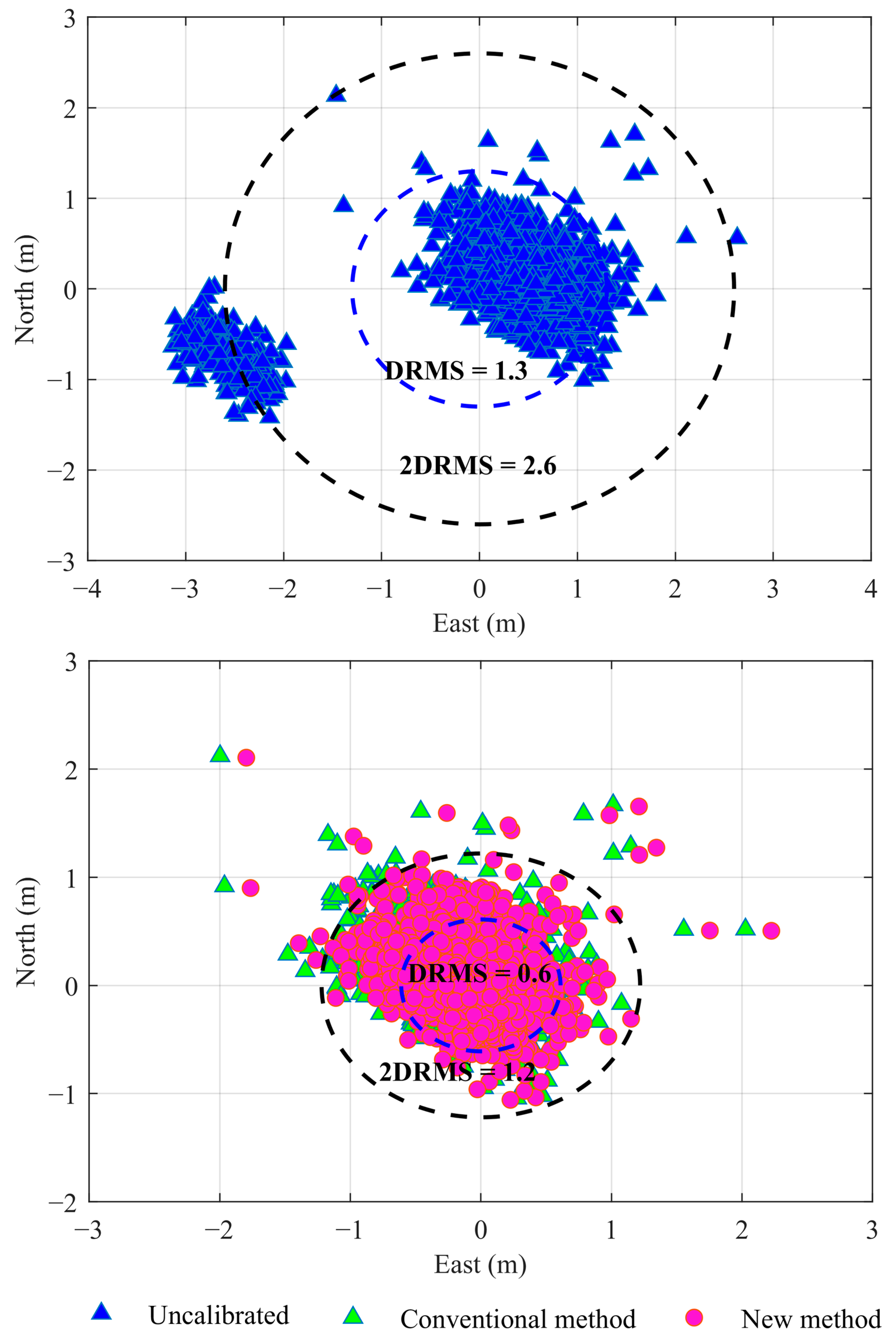
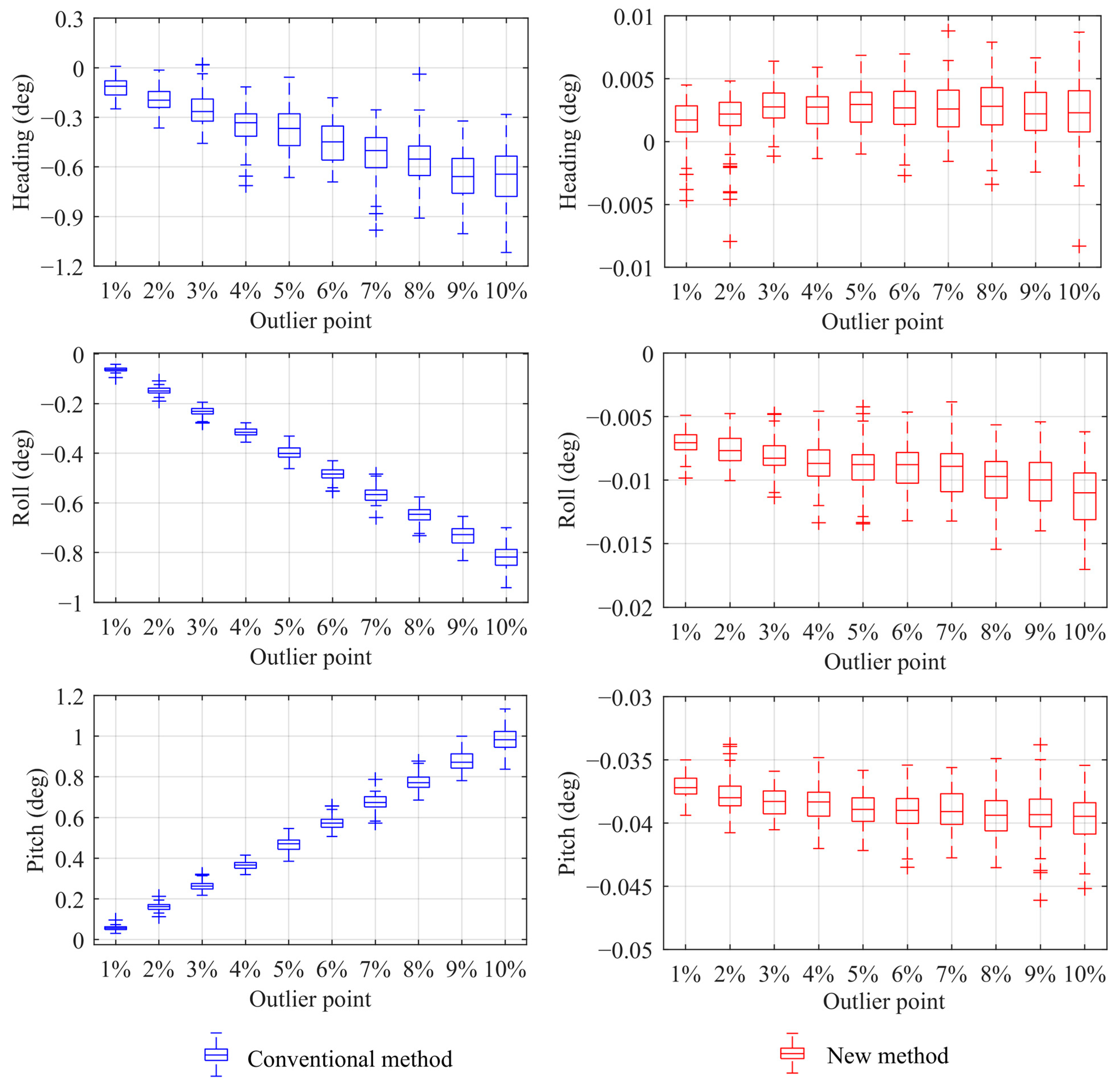
  • A sea trial was conducted to evaluate the performance of the proposed method. The conventional angle alignment method was likewise used for comparison. Compared to that of the conventional angle alignment method, the estimation precision of the proposed method was improved by approximately 0.0457°~0.6896° in heading, 0.0125°~0.8072° in roll, and 0.0077°~0.9436° in pitch. The angle misalignment estimates obtained by both methods were used to perform USBL underwater positioning. The accuracy of USBL underwater positioning with the proposed method was much better than that of the conventional angle alignment method. In summary, the proposed method has high calibration accuracy and robustness.

Author Contributions

Conceptualization, Z.S.; methodology, Z.S.; software, Z.S. and Z.N.; validation, Z.S., Z.W., C.J. and R.S.; formal analysis, Z.W.; data curation, Z.W.; writing—original draft preparation, Z.S.; writing—review and editing, Z.W., C.J. and R.S.; visualization, Z.S.; supervision, Z.W. All authors have read and agreed to the published version of the manuscript.

Funding

This research was funded by the National Key Research and Development Program (Grant No. 2021YFB3901300) and National Nature Science Foundation of China (Grant No. 42174020, 42174021). It was financially supported by Laoshan Laboratory (Grant No. LSKJ202205101) and Fundamental Research Funds for the Central Universities (Grant No. 22CX06032A).

Data Availability Statement

Data will be made available on request.

Acknowledgments

The authors would like to thank the editors and reviewers for their careful assessment of our work.

Conflicts of Interest

The authors declare no conflicts of interest.

Abbreviations

The abbreviations used in the manuscript as shown below:
USBLUltra-short baseline
GNSSGlobal navigation satellite system
GNSS/AGNSS/acoustic underwater positioning technique
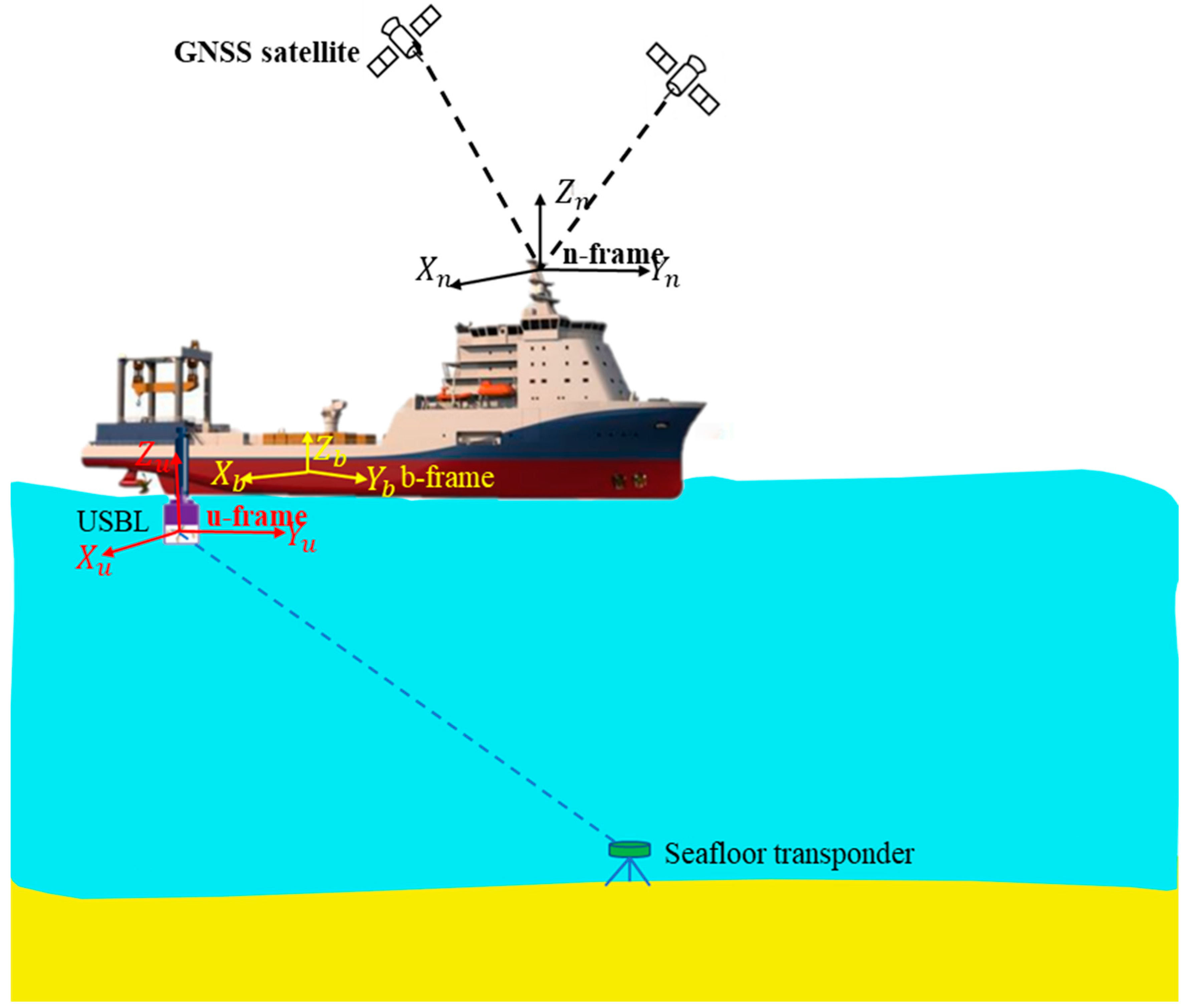
n-frameThe navigation reference framework
b-frameThe carrier reference framework
u-frameThe acoustic reference framework
STDStandard deviation
RMSRoot mean square

References

  1. Roberts, J. An advanced acoustic position reference system. In Proceedings of the 1975 Offshore Technology Conference, Houston, TX, USA, 5–8 May 1975. [Google Scholar] [CrossRef]
  2. Cui, W.; Zhou, X.; Jiang, Z. Ultra-short baseline positioning system for full ocean depth. Eng. Technol Open Access J. 2019, 3, 555601. [Google Scholar] [CrossRef]
  3. Chen, H. In-situ alignment calibration of attitude and ultra-short baseline sensors for precision underwater positioning. Ocean. Eng. 2008, 35, 1448–1462. [Google Scholar] [CrossRef]
  4. Fanelli, F.; Monni, N.; Palma, N.; Alessandro, R. Development of an ultra-short baseline–aided buoy for underwater targets localization. J. Eng. Marit. Environ. 2019, 233, 1212–1225. [Google Scholar] [CrossRef]
  5. Pan, S.; Xu, X.; Zhang, L.; Yao, Y. A novel SINS/USBL tightly integrated navigation strategy based on improved ANFIS. IEEE Sens. J. 2022, 22, 9763–9777. [Google Scholar] [CrossRef]
  6. Luo, Q.; Yan, X.; Wang, C.; Shao, Y.; Zhou, Z.; Li, J.; Hu, C.; Wang, C.; Ding, J. A SINS/DVL/USBL integrated navigation and positioning IoT system with multiple sources fusion and federated Kalman filter. J. Cloud Comput. 2022, 11, 5–17. [Google Scholar] [CrossRef]
  7. Morgado, M.; Oliveira, P.; Silvestre, C. Posterior Cramér-Rao bounds analysis for INS/USBL navigation systems. IFAC Proc. Vol. 2009, 42, 20–25. [Google Scholar] [CrossRef]
  8. Xu, B.; Guo, Y.; Jiang, Z.; Wang, X. An invariant error-based SINS/DVL/USBL tightly coupled integrated navigation algorithm and its robust state estimator. Ocean. Eng. 2024, 292, 116511. [Google Scholar] [CrossRef]
  9. Chen, G.; Xu, Y.D.; Wang, Z.Y.; Tu, J.J.; Hu, H.S.; Chen, C.; Xu, Y.H.; Chai, X.X.; Zhang, J.J.; Shi, J.W. Dynamic tail modeling and motion analysis of a beaver-like robot. Nonlinear Dyn. 2024, 112, 6859–6875. [Google Scholar] [CrossRef]
  10. Wang, B.R.; Chen, J.Y.; Cui, X.H. Model-free optimal robust tracking control for the joint actuated by pneumatic artificial muscles with saturated air pressure input. Control. Eng. Pract. 2024, 143, 15805. [Google Scholar] [CrossRef]
  11. Chen, G.; Xu, Y.D.; Yang, X.; Hu, H.S.; Cheng, H.; Zhu, L.Y.; Zhang, J.G.; Shi, J.W.; Chai, X.X. Target tracking control of a bionic mantis shrimp robot with closed-loop central pattern generators. Ocean. Eng. 2024, 297, 116913. [Google Scholar] [CrossRef]
  12. Zhang, D.P.; Zhao, B.W.; Zhang, Y.; Zhou, N. Numerical simulation of hydrodynamics of ocean-observation-used remotely operated vehicle. Front. Mar. Sci. 2024, 11, 1357144. [Google Scholar] [CrossRef]
  13. Vesin, A.; Tonchia, H. A rigging of a USBL transceiver for use on a seismic vessel. In Proceedings of the 2013 OCEANS, San Diego, CA, USA, 23–27 September 2013; pp. 1–3. [Google Scholar] [CrossRef]
  14. Zhang, T.; Liu, B.; Liu, Y. Positioning systems for Jiaolong deep-sea manned submersible: Sea trial and Application. IEEE Access 2018, 6, 71644–71650. [Google Scholar] [CrossRef]
  15. Zhang, T.; Tang, J.; Qin, S.; Wang, X. Review of Navigation and Positioning of Deep-sea Manned Submersibles. J. Navig. 2019, 72, 1021–1034. [Google Scholar] [CrossRef]
  16. Zhang, T.; Zhang, L.; Shin, H.S. A novel and robust calibration method for the underwater transponder position. IEEE Trans. Instrum. Meas. 2020, 70, 9500512. [Google Scholar] [CrossRef]
  17. Zhao, S.; Liu, H.; Xue, S.; Wang, Z.; Xiao, Z. Two-Step Correction Based on In-Situ Sound Speed Measurements for USBL Precise Real-Time Positioning. Remote Sens. 2023, 15, 5046. [Google Scholar] [CrossRef]
  18. Liu, H.M.; Sun, Z.; Nie, Z. Investigation on Precise Adjustment Model of the USBL Calibration Observations for Angular Misalignment. In Proceedings of the 2023 IEEE International Conference on Mechatronics and Automation, Harbin, China, 6–9 August 2023; pp. 2107–2111. [Google Scholar] [CrossRef]
  19. Zhu, Y.; Zhang, T.; Xu, S.; Shin, H.; Li, P.; Zhang, L.; Wang, C.; Li, Y. A calibration method of USBL installation error based on attitude determination. IEEE Trans. Veh. Technol. 2020, 69, 8317–8328. [Google Scholar] [CrossRef]
  20. Cuie, Z.; Dajun, S.; Dianlun, Z.; Xiang, L. Precise calibration of installation error in ultra-short baseline acoustic positioning systems. J. Harbin Eng. Univ. 2007, 54, 3218. [Google Scholar] [CrossRef]
  21. Guo, H.; Qian, Z.; Wang, X.; Sun, W.; Li, J.; Zhai, J. A robust attitude estimation algorithm for seabed inverted ultra-short baseline. Ocean. Eng. 2023, 280, 114534. [Google Scholar] [CrossRef]
  22. Sun, D.; Ding, J.; Zheng, C.; Huang, W. Angular misalignment calibration method for ultra-short baseline positioning system based on matrix decomposition. IET Radar Sonar Navig. 2019, 13, 456–463. [Google Scholar] [CrossRef]
  23. Sun, D.; Ding, J.; Zheng, C.; Huang, W. Array geometry calibration for underwater compact arrays. Appl. Acoust. 2019, 145, 374–384. [Google Scholar] [CrossRef]
  24. Nie, Z.; Wang, B.; Wang, Z.; He, K.F. An offshore real-time precise point positioning technique based on a single set of BeiDou short-message communication devices. J. Geod. 2020, 94, 78. [Google Scholar] [CrossRef]
  25. Sun, Z.; Wang, Z.; Nie, Z.; Zhao, S.; Yu, Y. Improved GNSS/Acoustic underwater positioning with between-buoy baseline constraint. J. Surv. Eng. 2023, 149, 04023012. [Google Scholar] [CrossRef]
  26. Xue, S.Q.; Li, B.J.; Xiao, Z.; Sun, Y.; Li, J. Centimeter-level-precision seafloor geodetic positioning model with self-structured empirical sound speed profile. Satell Navig. 2023, 4, 30. [Google Scholar] [CrossRef]
  27. Sun, D.; Lu, M.; Mei, J.; Wang, S.; Pei, Y. Generalized radon transform approach to target motion parameter estimation using a stationary underwater vector hydrophone. J. Acoust. Soc. Am. 2021, 150, 952–968. [Google Scholar] [CrossRef] [PubMed]
  28. Liu, B.; Da, L.; Zhang, X.; Jia, S.; Zou, S.; Tian, D. Ultra-short baseline positioning delay estimation based on signal preprocessing and fourth-order cumulant. AIP Adv. 2023, 13, 045308. [Google Scholar] [CrossRef]
  29. Sun, D.; Ding, J.; Zheng, C.; Huang, W. An Underwater acoustic positioning algorithm for compact arrays with arbitrary configuration. IEEE J. Sel. Top. Signal Process. 2019, 13, 120–130. [Google Scholar] [CrossRef]
  30. Sun, D.; Gu, J.; Han, Y.F.; Zhang, J.C. Inverted ultra-short baseline signal design for multi-AUV navigation. Appl. Acoust. 2019, 150, 5–13. [Google Scholar] [CrossRef]
  31. Honsho, C.; Kido, M.; Ichikawa, T.; Ohashi, T.; Fujimoto, H. Application of Phase-Only Correlation to Travel-Time Determination in GNSS-Acoustic Positioning. Front. Earth Sci. 2021, 9, 600732. [Google Scholar] [CrossRef]
  32. Sun, Z.; Wang, Z.; Nie, Z. A stochastic model for precise GNSS/acoustic underwater positioning based on transmission loss of signal intensity. GPS Solut. 2023, 27, 202. [Google Scholar] [CrossRef]
  33. Chang, X.W.; Guo, Y. Huber’s M-estimation in relative GPS positioning: Computational aspects. J. Geod. 2005, 79, 351–362. [Google Scholar] [CrossRef]
  34. Huber, P.J. Robust estimation of a location parameter. Ann. Math. Stat. 1964, 35, 73–101. [Google Scholar] [CrossRef]
  35. Xue, S.; Dang, Y.; Mi, J.; Zhang, C.; Li, D.; Yang, Q. Nonlinear and Robust Location for Low-cost Shipborne Laser Ranging Positioning. Mar. Geod. 2016, 40, 123–141. [Google Scholar] [CrossRef]
Figure 1. Map of the USBL alignment experiment with a research vessel. The u-frame, b-frame and n-frame are the acoustic reference framework, the carrier reference framework, and the navigation reference framework, respectively.
Remotesensing 16 02584 g001
Figure 2. Angle misalignment errors between the u-frame and the b-frame, in which the English letters (AD) represent the u-frame, the heading misalignment error, the pitch misalignment error, and the roll misalignment error, respectively.
Remotesensing 16 02584 g002
Figure 3. Flowchart of angle alignment data processing, including the construction of the angle alignment model and angle misalignment estimation. The English letters (A,B) represent the construction of the angle alignment model and angle misalignment estimation, respectively.
Remotesensing 16 02584 g003
Figure 4. The major equipment used in the USBL calibration experiment.
Remotesensing 16 02584 g004
Figure 5. Real data were collected from a sea trial carried out in the South China Sea.
Remotesensing 16 02584 g005
Figure 6. Bearing angles between acoustic transducer and seafloor transponder provided by USBL underwater positioning system.
Remotesensing 16 02584 g006
Figure 7. The error of USBL underwater positioning with and without angle calibration. The DRMS represents the root mean square (RMS) value of positioning error in horizontal direction, while 2DRMS indicates twice this value.
Remotesensing 16 02584 g007
Figure 8. Schematic diagram of transponder’s coordinates residuals after adjustment, in which the black and red lines are twice the RMS values and triple the RMS value of coordinate residuals, respectively.
Remotesensing 16 02584 g008
Figure 9. Error comparison of angle misalignment estimation with two methods at different outlier contamination rates, in which the blue box and red box represent the conventional angle-calibration method and the proposed robust angle-calibration method, respectively.
Remotesensing 16 02584 g009
Table 1. Statistical results of the bearing angles in three directions (unit: deg.).
EastNorthUp
MinMaxMeanMinMaxMeanMinMaxMean
data146.2848.0047.2251.5353.4452.5338.5741.0639.70
data254.9955.7555.3840.4143.8142.0039.8743.4941.63
data343.3245.5544.2856.2657.0156.7136.3338.1437.27
data454.5655.5955.1446.6349.6247.9332.7836.7835.03
data557.2857.3057.2956.1157.1056.644.8311.688.55
data657.0057.2957.2157.0757.3057.222.616.174.23
Table 2. Statistics of estimation errors in heading misalignment, roll misalignment, and pitch misalignment for two methods (unit: deg.).
MethodAngle Misalignment EstimationEstimation Error
HeadingRollPitchHeadingRollPitch
Conventional method−5.9281−0.0197−0.1159−0.04810.02030.0459
New method−5.8776−0.0478−0.10820.0024−0.00780.0382
Table 3. Statistics results of positioning errors with and without angle calibration (unit: m).
STDRMS
EastNorthUp2-D3-D
Uncalibrated1.20840.52020.45751.31561.3929
Conventional method0.44700.40350.45120.60220.7525
New method0.41730.39970.44860.57780.7315
Table 4. Statistical results with two methods under different outlier conditions (unit: deg.).
RateHeadingRollPitch
Conventional MethodNew MethodConventional MethodNew MethodConventional MethodNew Method
1%0.13100.00240.06340.00710.05700.0371
2%0.20280.00270.14900.00770.16190.0378
3%0.27190.00320.23270.00820.26460.0384
4%0.36380.00300.31490.00870.36540.0384
5%0.39150.00340.39940.00910.46900.0389
6%0.46820.00330.48460.00900.57350.0390
7%0.52840.00330.56790.00930.67570.0390
8%0.57730.00360.64830.01010.77430.0394
9%0.67480.00310.73510.01020.88090.0393
10%0.69310.00350.81870.01150.98340.0398
Disclaimer/Publisher’s Note: The statements, opinions and data contained in all publications are solely those of the individual author(s) and contributor(s) and not of MDPI and/or the editor(s). MDPI and/or the editor(s) disclaim responsibility for any injury to people or property resulting from any ideas, methods, instructions or products referred to in the content.

