Abstract
Waveform design for integrated radar and jamming is generally based on the concept of shared waveform, which uses jamming signals without typical radar signal characteristics for detection. Existing waveforms have shown limited design flexibility, high levels of sidelobe in detection results, and overall ordinary performance. We propose an integrated radar and jamming waveform based on smart modulation and complementary coding. Unlike traditional integrated radar and jamming waveform based on smart modulation, the phase angle of the binary phase-coded sequence is adjustable in this smart modulation method, allowing for a controllable jamming effect, achieving true smart modulation. However, this smart modulation waveform also suffers from high sidelobes in detection. To address this issue, we take a complementary coding approach and design a smart modulation waveform with complementary characteristics. This waveform can synthesize a complete linear frequency modulation (LFM) signal by adding two pulses together, thereby reducing the sidelobes in the smart modulation waveform and enhancing its detection performance. Theoretical analysis indicates that the detection and jamming effects of this integrated waveform can be flexibly controlled by adjusting the phase angles of the coding sequences. Simulation analysis and experimental results confirm the significant advantages of this waveform.
1. Introduction
Electronic warfare (EW) is a process in the mutual game between radar, communication, and other systems on the core electromagnetic spectrum and its adversaries [1]. With the rapid development of software and hardware, to reduce costs and minimize mutual interference between devices, electronic warfare is gradually evolving from a combination of various independent devices to multifunctional integrated electronic warfare systems [2]. Integrated waveforms that can simultaneously achieve functions such as detection and jamming are essential for integrating electronic warfare systems. From the perspectives of detection and jamming, a shared waveform design approach can be utilized to implement both functions with an integrated waveform. Different functions can share time, frequency, space, and other resources, enhancing the overall utilization of system resources [3].
A considerable amount of research has been conducted by scholars in the field of waveform design for integrated radar and jamming. A reasonable approach is to start from the perspective of jamming waveforms (such as suppression jamming and deception jamming [4]), make certain improvements, and thereby develop integrated radar and jamming waveforms.
We will start from the perspective of suppression jamming waveforms. The authors of reference [5] proposed directly using binary phase-coded pseudo-random signals as a type of integrated radar and jamming waveform. The authors of reference [6] considered noise frequency modulation (NFM) signals as a type of integrated radar and jamming waveform, which demonstrated better overall performance in terms of detection and jamming compared to binary phase-coded pseudo-random signals. In reference [7], an improved chaos genetic algorithm was employed to design an integrated waveform based on pseudo-random binary phase-coded signals. This waveform exhibited a good jamming effect on both linear frequency modulation (LFM) signals and traditional binary phase-coded signals. In terms of deception jamming, the authors of reference [8] took the intercepted LFM signal from the adversary’s radar as prior information, then modulated the LFM signal using binary phase-coded pseudo-random sequences to obtain an integrated signal based on smart modulation, which can achieve a good coherent jamming effect. The authors of reference [9] processed the intercepted LFM signal through phase modulation and delay forwarding to design an integrated signal that can cause multi-order false target jamming to the adversary’s radar. The authors of reference [10] used Costas sequences to encode the intra-pulse frequency of LFM signals to generate an integrated signal that can cause varying degrees of coherent jamming to the adversary’s radar. A comprehensive review of existing research on integrated radar and jamming waveform reveals that the essence of integrated radar and jamming waveform lies in utilizing traditional jamming signals for detection. To ensure effective jamming, the jamming waveform needs to possess a certain degree of randomness. However, this requirement leads to integrated radar and jamming waveforms exhibiting higher levels of range sidelobes and Doppler sidelobes compared to traditional LFM detection waveforms when used for detection. In scenarios involving multi-target detection or detection in strong clutter environments, the sidelobes of strong targets or clutter may mask small targets, leading to the missed detection of small targets [11] and significantly impacting target detection performance.
Currently, there is no optimal solution to the issue of high sidelobes in detection for integrated radar and jamming waveforms. However, upon reviewing the literature, we have found that a similar issue exists in the field of noise radar detection. Noise radars employ waveforms with certain random characteristics in order to achieve low interception and anti-jamming capabilities, which is similar to the characteristics of existing integrated radar and jamming waveforms. There are some existing studies on the suppression of range and Doppler sidelobes for random waveform, which may have a certain value for addressing the issue of high sidelobes in integrated radar and jamming waveform. For the suppression of detection sidelobes for random waveform, existing studies have explored the issue from both the perspectives of signal processing and waveform design. From the perspective of signal processing, the author of reference [12] has achieved the goal of reducing sidelobes by replacing the matched filter with optimized filter weights based on the mismatched filter concept. References [13,14,15,16,17] presented various methods for optimizing signal processing filter designs, all of which can achieve a certain degree of sidelobe suppression. However, the cost of using these methods is a significant loss in signal-to-noise ratio (SNR) gain, resulting in reduced detection power. From the perspective of waveform design, references [18,19,20,21,22] introduced complementary codes and various optimized models of complementary codes. The positive and negative codes of complementary codes can complement each other to cancel out sidelobes after pulse compression, effectively addressing the issue of high sidelobes in random waveform detection. However, the essence of these complementary codes is still phase-coded signals, which are highly suitable for detection applications. When used for integrated radar and jamming waveforms, their jamming performance is limited. Complementary coded waveforms based on phase-coded sequences can only generate a jamming effect in a form similar to suppression, resulting in a single type of jamming. On the other hand, complementary coded waveforms based on phase-coded sequences need to be strictly generated according to the designed code groups, leading to a certain inter-group periodicity in the emitted waveforms. When used for integrated radar and jamming waveforms, they are susceptible to being recognized and analyzed by adversaries due to the regular patterns, thus influencing the effect of the jamming [23]. To address this issue, we proposed an integrated radar and jamming waveform based on smart modulation and complementary coding. This waveform is based on intercepting the LFM signals emitted by the adversary’s radar. Within a single pulse, we used phase-angle-adjustable binary-coded random sequences to smartly modulate the LFM signal, achieving a smart jamming effect and enabling flexible transformation between suppression and deception jamming effects. Meanwhile, we designed corresponding waveform generation and signal processing methods based on complementary coding between adjacent pulses. Through inter-pulse complementarity, we achieved a detection performance that is close to traditional LFM pulse Doppler radar. This approach significantly reduces sidelobes compared to traditional integrated radar and jamming waveforms, ensuring its detection performance in scenarios with strong clutter and high dynamics.
The main contributions of this paper are as follows:
- Proposing a waveform design and processing method for integrated radar and jamming based on smart modulation and complementary coding, solving the issue of high sidelobes in traditional integrated radar and jamming waveforms;
- Theoretical derivation and analysis of the influence of phase angles of coding sequences on the detection and jamming effects of integrated waveform are provided. A method for adjusting detection and jamming performance is proposed, allowing for the flexible control of the jamming effect by changing the phase angles;
- The superior detection and jamming performance of the proposed waveforms is demonstrated through experimental results.
The remainder of this paper is organized as follows. Section 2 introduces the working scenario of integrated radar and jamming systems. Section 3 discusses the issues that still exist in the traditional integrated radar and jamming waveform design and processing. Section 4 presents the proposed waveform design and signal processing methods for integrated radar and jamming. Section 5 theoretically analyzes the impact of the phase angles of coding sequences on the detection and jamming effects of integrated waveforms. Section 6 conducts simulation analysis based on theoretical derivations. Section 7 verifies the superiority of the proposed integrated signal through experiments. Finally, Section 8 summarizes the research content of this paper.
2. The Working Scenarios of Integrated Radar and Jamming Systems
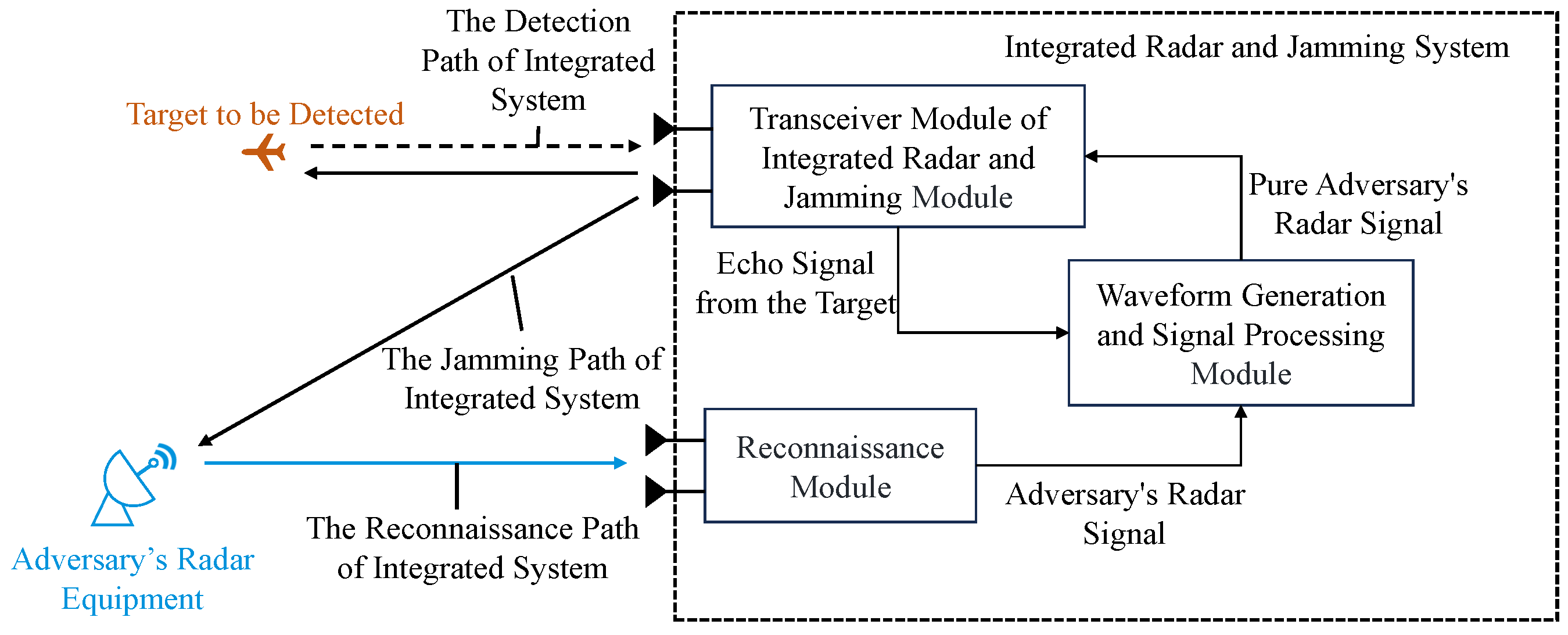
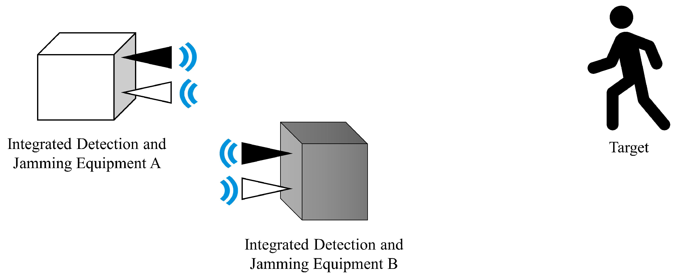
In the electronic warfare scenario [24], the adversary’s equipment emits radar signals for target detection. Our integrated radar and jamming equipment first detects and intercepts the adversary’s radar signals, modulating them to form integrated signals with both detection and jamming functions. The emitted integrated signals not only interfere with the adversary’s radar detection but also enable detection by receiving echoes reflected by targets, thereby improving the utilization of system resources. The generation process of integrated waveforms and the implementation of detection and jamming functions in the working scenario of integrated radar and jamming equipment are depicted in Figure 1.
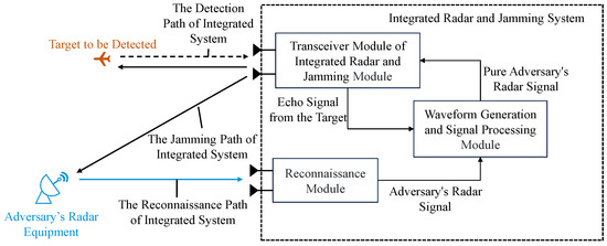
Figure 1.
The generation process of integrated radar waveforms and a schematic diagram of the working scenario of integrated equipment.
3. Limitations of Traditional Integrated Radar and Jamming Waveforms and Signal Processing Methods
The essence of integrated radar and jamming waveforms lies in utilizing jamming signals to illuminate targets and then receive echoes from targets for detection. In the early stages of research in this field, some researchers utilized pseudo-random binary phase-coded signals as integrated radar and jamming signals [5], but their overall performance in detection and jamming was found to be inadequate. Some scholars have adopted smart modulation to generate integrated radar and jamming waveforms [8]. In designing such waveforms, the first step involves intercepting the adversary’s radar signals. Considering that the radar emits classic LFM detection waveforms, its baseband form can be expressed as
where , B, and are the bandwidth and pulse width of the LFM signal.
The phase-coded signal used in the traditional integrated radar and jamming waveform can be expressed as
where is the phase modulation function. For binary phase-coded signals, generally takes only two values, 0 and . After intercepting the adversary’s LFM signal, to generate a jamming effect, it can be multiplied by a locally generated pseudo-random phase-coded signal . Therefore, the traditional integrated radar and jamming waveform based on smart modulation can be expressed as
This waveform can effectively interfere with the adversary’s radar as a jamming signal, and its reflected echoes can be processed through conventional echo processing procedures, such as pulse compression and moving target detection (MTD) [25], to obtain target information, thereby achieving integrated radar and jamming. While this integrated waveform shows improved detection and jamming performance compared to pseudo-random binary phase-coded signals, it still faces challenges such as high range and Doppler sidelobes during detection. Sidelobes caused by strong targets may mask the main peak of small targets [26], limiting the detection performance of small targets in the presence of strong clutter [11]. Figure 2 illustrates the range-Doppler map when using this traditional integrated radar and jamming waveform to detect both strong and weak targets. The sidelobes of the strong target are higher than the peak of the weak target. When both targets coexist in the environment, the weak target may go undetected due to being masked by the sidelobes of the strong target.
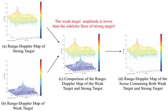
Figure 2.
The effect of strong target sidelobes masks weak targets when using high-sidelobe signals for detection.
4. Design and Processing Model of Integrated Radar and Jamming Waveform Based on Smart Modulation and Complementary Coding
The phase-coded signal used in the integrated radar and jamming waveform based on smart modulation and complementary coding can be expressed as
where is the phase modulation function, which, for the binary phase-coded signal used in the proposed integrated waveform, only takes two values, and . The resulting proposed integrated waveform can be expressed as
If each coherent processing interval (CPI) of the integrated radar and jamming waveform contains N pulses, then the pulse signal of the nth pulse of the integrated waveform can be expressed as
where is the binary phase-coded sequence of the nth pulse, and is the rectangular envelope function, which can be expressed as
Therefore, if we only observe a single pulse, remains in the form of a binary phase-coded modulated LFM signal. The difference between this integrated waveform and traditional integrated radar and jamming waveform based on smart modulation lies in the following aspects:
- 1.
- The coding sequences used in this integrated waveform have complementary relationships between pulses, which can be added to obtain a complete LFM signal with a constant modulus, while the coding sequences used in the traditional integrated waveforms are completely random, which severely affects the detection performance of the integrated waveform.
- 2.
- The phase of the coding sequence is not limited to 0 and , but can be arbitrarily selected, ensuring flexible and variable detection and jamming effects.
In the proposed integrated waveform, the phase-coded sequences between adjacent pulses need to satisfy the following relationship:
where m is a sequence of positive integers, is a sequence of even numbers, and is a sequence of odd numbers, pairing the N pulses in pairs, where the coding values at the same time instant between each pair of pulses are different. The addition of signals from adjacent two pulses can be expressed as
where , , is a complex constant. Therefore, at any given time, the addition of each pair of emitted pulses results in a complete LFM signal. When the intercepted radar signals are not LFM signals, the proposed modulation method remains effective. By modulating the intercepted radar signal x with a phase-coded signal, coherent jamming can be generated for the adversary’s radar detection. Then, based on the complementarity of the waveform, the complete signal x can be reconstructed, allowing for the effective implementation of both detection and jamming functions.
To examine the echoes of this waveform when used for detection, the echo of a point target corresponding to the nth pulse during detection can be expressed as
If the echoes corresponding to adjacent emitted pulses are added together, then
where is an approximate value of the delay between the and pulses, since the pulse repetition interval (PRI) of radar signals is generally short and the deviation in the delay caused by target motion is negligible [27], meaning this approximation is reasonable. When , where is the PRI of the integrated waveform, the expression for the sum of the echoes from adjacent pulses can be transformed into
In order to highlight the time delay information carried by the echo, the pulse compression result for Equation (12) can be expressed as [28]
where , . From Equation (13), it can be observed that the pulse compression result takes the form of a sinc function, with the function reaching its maximum value at the delay position, thereby reflecting the target’s range information. To obtain the target’s velocity information, MTD processing is applied to multiple pulses after pulse compression. The envelope of the coherent pulses train can be expressed as
The amplitude of the spectrum function obtained by the Fourier transform of Equation (14) can be expressed as [29]
from Equation (15), it can be observed that the function reaches its maximum value when and the Doppler velocity information of the target is reflected through the Fourier transform of the coherent pulses train.
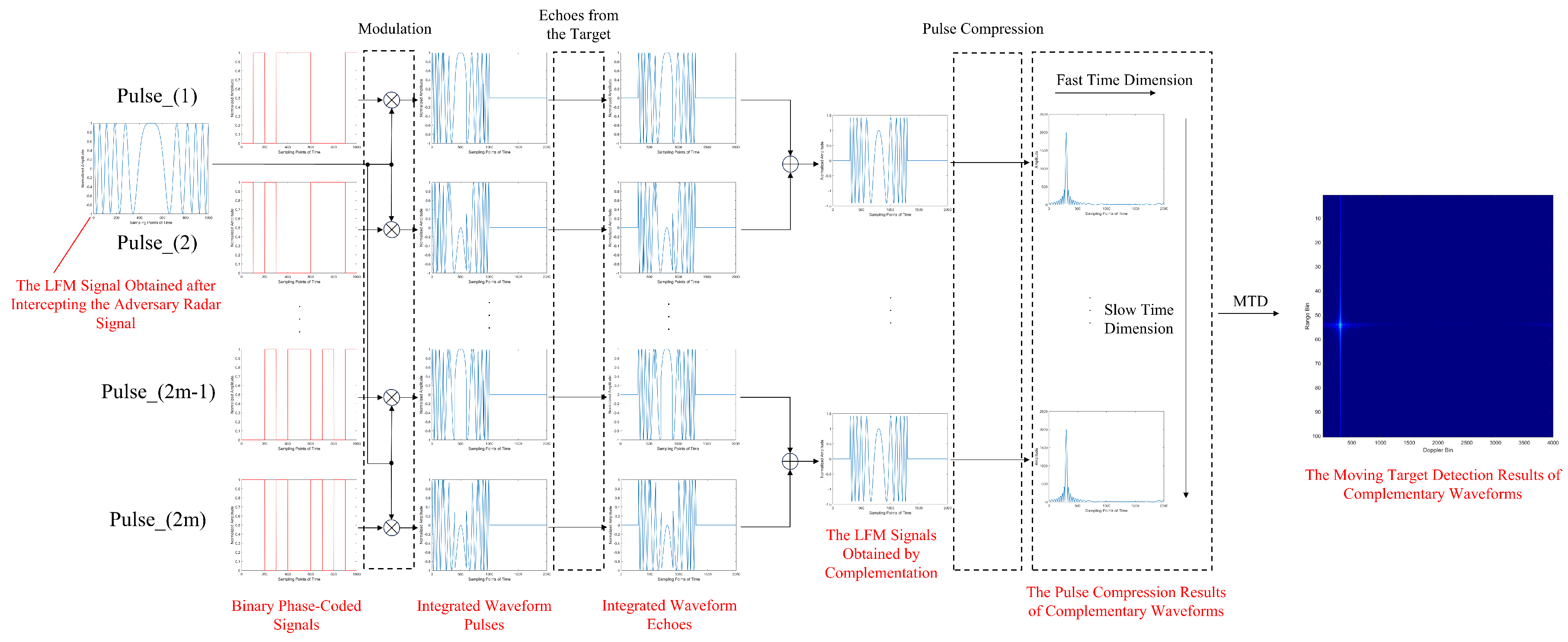
The corresponding waveform design and processing method are shown in Figure 3. The intercepted LFM signal is modulated by a binary phase-coded signal that is random within pulses but complementary between adjacent pulses to obtain the proposed integrated waveform pulses train. This signal serves as a jamming signal to interfere with the adversary’s radar, while also serving as a detection signal that forms echoes through target reflection [30]. After receiving the echo signals, the integrated system can divide the echo pulses train into complementary pairs, and add together pulses within each pair, thus restoring LFM signals with target delay and Doppler information. Subsequently, through pulse compression and MTD processing, the range-Doppler map of the target can be obtained, extracting range and velocity information.
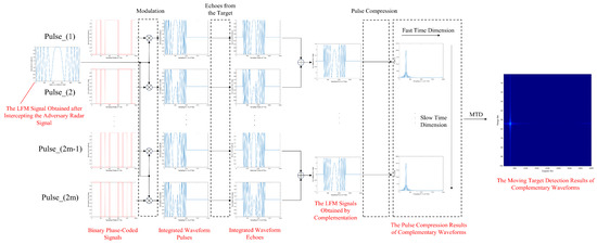
Figure 3.
Schematic diagram of the design and processing of integrated radar and jamming waveform based on smart modulation and complementary coding.
5. Waveform Detection and Jamming Performance Control
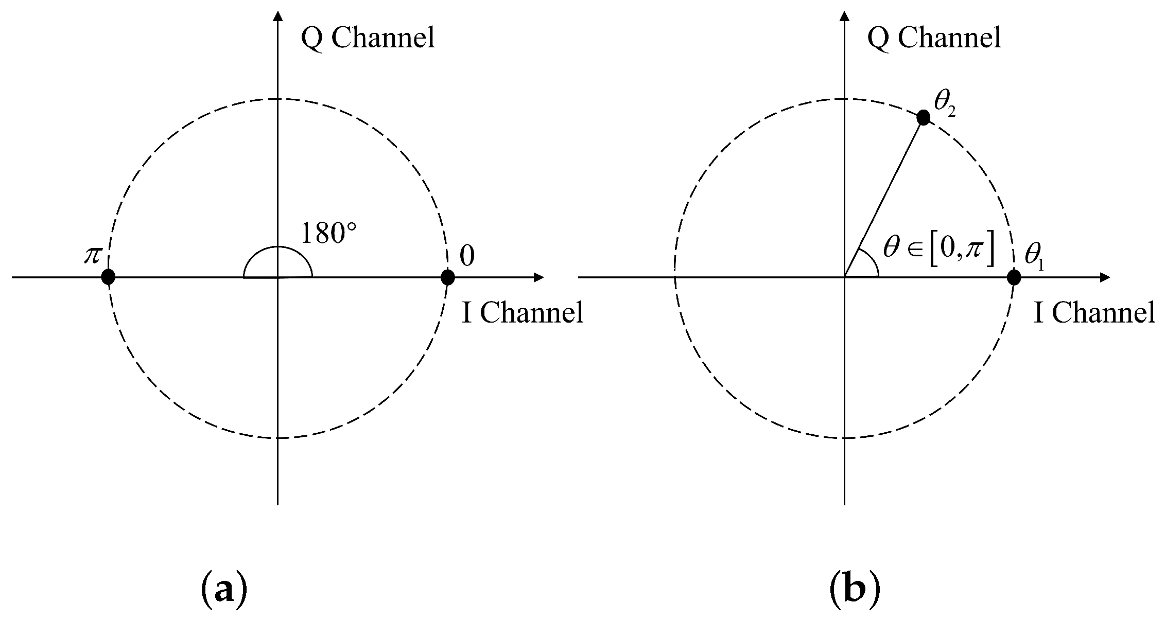
Compared with traditional integrated radar and jamming waveforms based on smart modulation, the proposed integrated waveform not only enhances detection performance through waveform complementarity but also allows for the flexible control of the detection and jamming performance of the integrated waveform by adjusting the magnitude of the phase angle. The constellation diagram of traditional binary phase-coded signals and the constellation diagram of the proposed binary phase-coded signals are shown in Figure 4 for comparison.
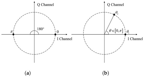
Figure 4.
The comparison of the constellation diagrams between (a) traditional binary phase-coded signals and (b) the proposed binary phase-coded signals.
Where represents the angle between the phase angle and the phase angle . One major advantage of the proposed integrated waveform is the ability to control detection and jamming effects using phase angles flexibly. The following section first theoretically analyzes the influence of phase angles on detection and jamming effects and then designs corresponding strategies for controlling detection and jamming effects.
5.1. The Influence of Phase Angle on Detection Effect
Although the proposed integrated waveform addressed the issue of high detection sidelobes by synthesizing LFM signals through complementary adjacent pulses, the angular jump between the phase components of the binary phase-coded sequences of different pulses may affect the SNR gain of the synthesized signal. To analyze the detection performance [31] of the proposed integrated signal, the SNR gain of the integrated signal after pulse compression is compared with that of the traditional integrated signal after pulse compression. The pulse pairs of the proposed integrated signal can be expressed as
Focusing on a stationary target and taking environmental noise interference into account, the detection of the target using the pulse pairs of the integrated signal can be described as follows: transmitting during the first PRI and transmitting during the second PRI. The echoes can be expressed as
where is the delay of the echo, and are Gaussian white noises for the echoes of the two pulses, and and are the echoes of the two pulses. Utilizing the complementarity of the waveforms, the echo of the proposed integrated signal, obtained by adding the echoes of the two pulses, can be expressed as
where is the sum of and . To research the influence of the phase angle of the binary coded sequence on detection effect, we first calculated the SNR gain of the proposed integrated signal after the pulse compression of pulse , referred to as gain 1. Next, we calculated the sum of the SNR gains of the traditional integrated signal after the pulse compression of pulses and , referred to as gain 2. Finally, we obtained the ratio of gain 1 to gain 2 and analyzed the detection performance of the proposed integrated signal based on this ratio. The instantaneous power of the signal at a certain time can be expressed as [32]
where , , and are the system functions of the corresponding matched filters. Then, the average power of the filtered noise output under the two conditions can be expressed as [32]
where and are the power spectral density of noise input for the two pulses equal to two constants, and , respectively. Therefore, at time , the ratio of the instantaneous power of the filtered signal to the average power of noise in the two cases can be expressed as
According to the Schwartz inequality, the maximum output SNR in two cases can be expressed as
According to the Parseval’s theorem, the energy of a signal can be expressed as
Therefore, the maximum output SNR in two cases, one where the traditional integrated signal echoes undergo pulse compression, and the other where the proposed integrated signal echo is first complemented and then pulse compressed, can be expressed as
where and are the energy of signals from different PRIs, with the relationship and . Thus, the ratio of the maximum output SNR of the proposed method to that of the traditional integrated signal echo pulse compression processing can be expressed as
without the loss of generality, assuming , then . When , , the SNR gain ratio is 1, indicating that the proposed integrated waveform has good detection capability at this point. As increases, the SNR gain ratio decreases, and the detection capability of the integrated waveform diminishes. When , , the SNR gain ratio equals 0, indicating that the integrated waveform nearly loses its detection capability.
5.2. The Influence of Phase Angle on Jamming Effect
To analyze the jamming effect of the proposed integrated signal on the adversary’s radar, we can examine the cross-correlation characteristics between the two signals [33]. The stronger the cross-correlation, the easier it is for the jamming formed by our integrated waveform to cluster in the range-Doppler map of the adversary’s radar, resulting in a more concentrated distribution of jamming energy. Conversely, the weaker the cross-correlation, the harder it is for the jamming formed by our integrated waveform to cluster in the range-Doppler map of the adversary’s radar, leading to a more dispersed distribution of jamming energy. To analyze the cross-correlation characteristics, we first calculate the sum of the conjugate product of the integrated signal and the LFM signal of the adversary’s radar.
Equation (33) can be transformed into
where K is the number of sampling points within one chip duration, and H is the number of chips within the signal duration. If X is larger, then the correlation between the LFM signal and the integrated signal is stronger. If X is smaller, then the correlation between the LFM signal and the integrated signal is weaker.
This assumes that v is a randomly generated variable following a binomial distribution of , with only two possible values for and , where the probability of v taking the value of is p, and the probability of it taking the value of is . According to the Central Limit Theorem, when the sample size H is large enough, and each sample satisfies the conditions of being independently and identically distributed, the binomial distribution approximates a normal distribution. At this point, the expectation and variance of the samples can be, respectively, expressed as
Taking the simplest binary phase-coded sequence as an example, without the loss of generality, assuming , then . At this point, the binary phase-coded sequence can be represented as , . The expectation and variance of the samples can be simplified as
To clearly demonstrate the influence of phase angles on the jamming effect, the power of the sample expectation can be expressed as
where represents the degree of correlation between the integrated signal and the LFM signal, while represents the level of clutter of jamming caused by the integrated signal on the LFM signal.
In summary, the detection and jamming effects of the integrated signal are inter-conditioned. When , the detection effect of the integrated signal is optimal, approaching the detection capability of the LFM signal, with the jamming energy concentrated and the jamming effect akin to deception jamming. As the phase angle increases, the detection performance degrades, and the jamming energy becomes more dispersed. When , the jamming effect of the integrated signal approaches suppression jamming, and the waveform nearly loses its detection capability. Therefore, when the system requires high detection performance, we can reduce the phase angle to improve the detection effect of the waveform. Conversely, when the system prefers jamming to be in the form of suppression, we can increase the phase angle to make the jamming effect more dispersed.
6. Simulation Analysis
From the preceding analysis, it is evident that the proposed integrated waveform outperforms the traditional integrated waveform in terms of detection and jamming overall performance. Moreover, it can flexibly adjust the detection and jamming effects by tuning the phase angle of the binary phase-coded sequences. Below, a comparison between the proposed integrated waveform and the traditional integrated waveform will be conducted through simulation analysis. Firstly, a comparison of the detection results of the two waveforms on a point target will be simulated, revealing the significant advantage of the proposed integrated waveform. Then, the influence of the phase angle on the detection and jamming effects of the integrated waveform will be analyzed through simulation.
Taking the working scenario of the integrated device depicted in Figure 1 as the simulation basis, the parameters of the proposed integrated waveform are the same as those of the traditional integrated waveform. The parameters used in the simulation are shown in Table 1.

Table 1.
Parameter settings.
6.1. Analysis of Point Target Detection Performance
By comparing the detection results of point targets using the proposed integrated waveform and the traditional integrated waveform, we can observe the sidelobe levels of the targets when using the two waveforms for detection, respectively, thereby evaluating the effect of the detection. In the range dimension, applying a window can effectively reduce the range sidelobes of the proposed integrated waveform, but it has no optimization effect on the traditional integrated waveform. This is because the traditional integrated signal coding is inherently random, whereas the proposed integrated waveform, although exhibiting randomness within individual pulses, can obtain a deterministic signal through pulse-to-pulse waveform complementarity. Thus, it can benefit from the gain brought by windowing. In the absence of noise interference, with the phase angle set to , and the target moving at a velocity of 10 m/s, both types of signals were subjected to a Hamming window in the range dimension. The resulting comparison of detection results between the proposed integrated waveform and the traditional integrated waveform is shown in Figure 5a,b. In the range-Doppler map, the level of the sidelobes can be described by the ratio of the average energy of target sidelobes to the energy of the main target peak. The sidelobe level of the traditional integrated waveform in the range-Doppler map is −50.49 dB, while the sidelobe level of the proposed integrated waveform in the range-Doppler map is −72.48 dB, resulting in a reduction of 21.99 dB. Due to the Doppler sensitivity of the proposed integrated waveform, the sidelobes will significantly increase with the target velocity. Thus, when detecting targets at different velocities, the comparison of sidelobe levels in the range-Doppler maps of the proposed integrated waveform and the traditional integrated waveform is shown in Figure 5c. Under the simulation parameters listed in Table 1, when the target velocity is less than 210 m/s, the proposed integrated waveform outperforms the traditional integrated waveform in detection.
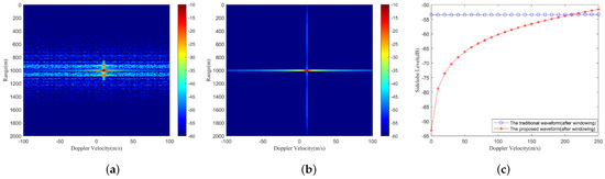
Figure 5.
The range-Doppler maps: (a) the traditional integrated waveform; (b) the proposed integrated waveform; (c) The comparison of sidelobe level between traditional integrated waveform and the proposed integrated waveform at different target velocities.
6.2. The Influence of Phase Angle on Detection and Jamming Effects
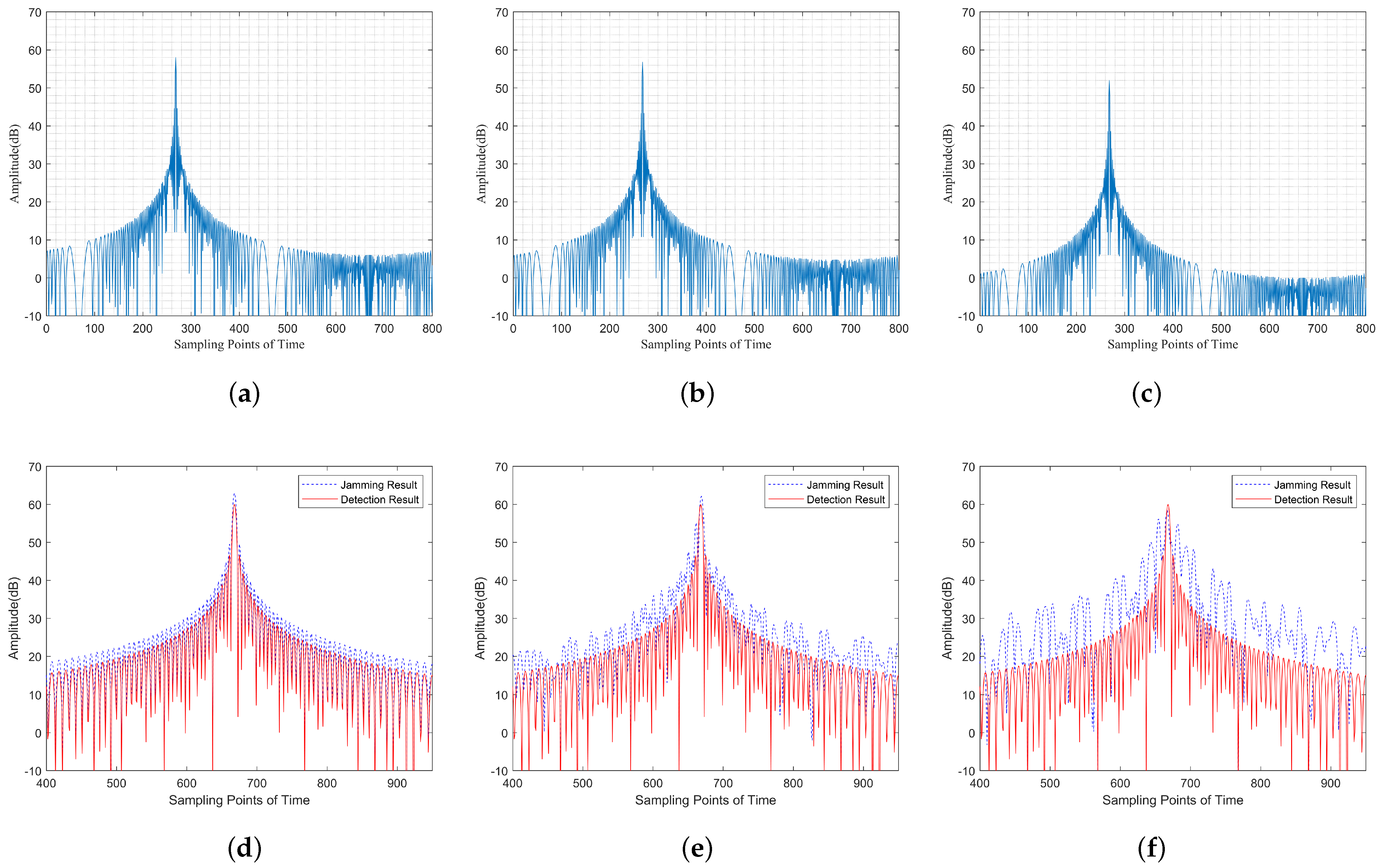
The proposed integrated waveform not only outperforms the traditional integrated waveform in terms of detection performance, it also offers the flexibility to adjust the phase angle to control detection and jamming effects. Taking a binary phase-coded sequence as an example, considering varying between , when the phase angles are , , and , respectively, the pulse compression results of the detection echoes using the proposed integrated waveform and the results of interfering with LFM signals using this waveform are shown in Figure 6. The intensity of the detection results is represented using non-normalized amplitudes. As the phase angle increases, the peak value of the target gradually decreases, and the detection power degrades gradually. The intensity of the jamming results is represented using non-normalized power. To clearly observe the jamming effect of the proposed integrated signal on the LFM signal, the intensity of the integrated signal is 3 dB higher than that of the LFM signal. As the phase angle increases, the peak power gradually decreases, and the energy gradually disperses out. The jamming effect gradually changes from deceptive jamming to suppressive jamming.
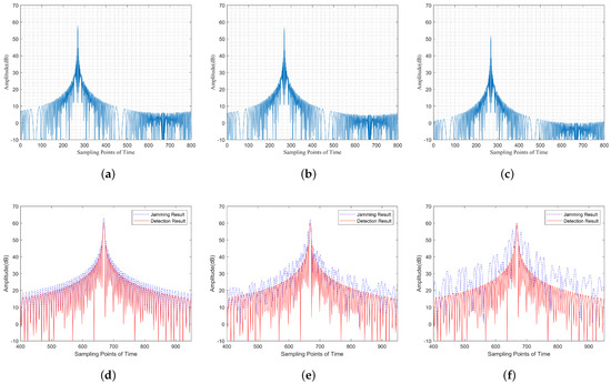
Figure 6.
Pulse compression results of the detection echoes using the proposed integrated waveform when the phase angle is (a) , (b) , (c) . The comparison of the jamming result of the proposed integrated waveform proposed in this paper on the LFM signal with the detection result of the LFM signal when the phase angle is (d) , (e) , and (f) .
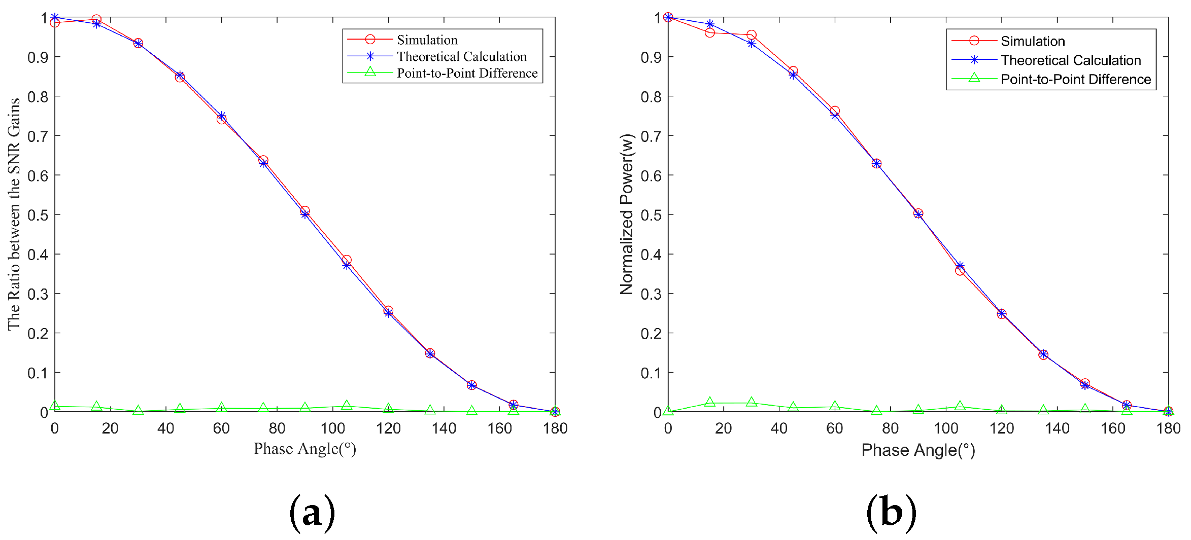
To analyze the influence of the phase angle on the detection effect, a Monte Carlo experiment was conducted 30 times. Initially, the echoes of the proposed integrated signal and the echoes of the traditional integrated signal were obtained. White noise with an SNR of 0 dB was then added to the echoes, followed by pulse compression to calculate the SNR gain for pulse compression using the proposed integrated waveform and for pulse compression using the traditional integrated waveform at different phase angles. Finally, the ratio of these gains was compared to the theoretical value curve corresponding to Equation (32). The comparison graph is depicted in Figure 7a, where the two curves mostly overlap, indicating consistency between the simulation analysis and the theoretical analysis. This means that the simulated results align well with the theoretical analysis.
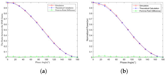
Figure 7.
The influence of phase angle on detection and jamming effects in simulation analysis and theoretical analysis: (a) curves of the ratio of the SNR gain changing with phase angle in simulation analysis and theoretical analysis, (b) curves of the jamming peak power changing with phase angle in simulation analysis and theoretical analysis.
To analyze the influence of the phase angle on jamming effects, a Monte Carlo experiment was conducted 30 times. Firstly, the echo of the proposed integrated signal was obtained, white noise with an SNR of 0 dB was then added to the echoes, and then pulse compression was performed with an LFM reference signal. This allowed us to obtain a curve showing the variation in peak power of the pulse compression results with different phase angles. This curve was then compared to the theoretical curve corresponding to Equation (39), as shown in Figure 7b. The two curves mostly overlap, indicating consistency between the simulation analysis and the theoretical analysis.
In summary, when , the ratio of the SNR gain for pulse compression using the proposed integrated waveform to that using the traditional integrated waveform is at its highest, indicating the greatest detection power, resulting in the best detection effect, with the jamming power peak being the highest and the jamming energy being the most concentrated. As the phase angle increases, the ratio of SNR gain begins to decrease, the detection power starts to degrade, the jamming power peak decreases, and jamming energy becomes more dispersed. This occurs until , where the detection effect is worst and jamming energy is most dispersed.
7. Data Processing for Experimental Results
To verify the detection and jamming effects of the integrated signal, an experimental verification system was set up, as shown in Figure 8. The project utilized a universal software radio peripheral (USRP) B210 for building the experimental verification system. A set of USRP devices was used as an integrated radar and jamming system. The signal processing flow is as follows: Firstly, digital baseband emitted signals are generated by a general-purpose computer. These signals are then processed by the USRP to produce radio frequency (RF) signals emitted by the transmitting antenna. The signals are reflected by the target and received by the receiving antenna. The RF-received signals are then processed by the USRP to convert them into digital baseband received signals, which are input to the general-purpose computer for next processing. The entire experimental verification system consists of two sets of integrated radar and jamming systems. The parameters used for the experimental verification are shown in Table 2.
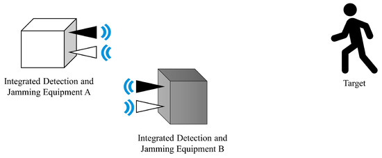
Figure 8.
The working scenario of the experiment.
Table 2.
Experimental parameters.
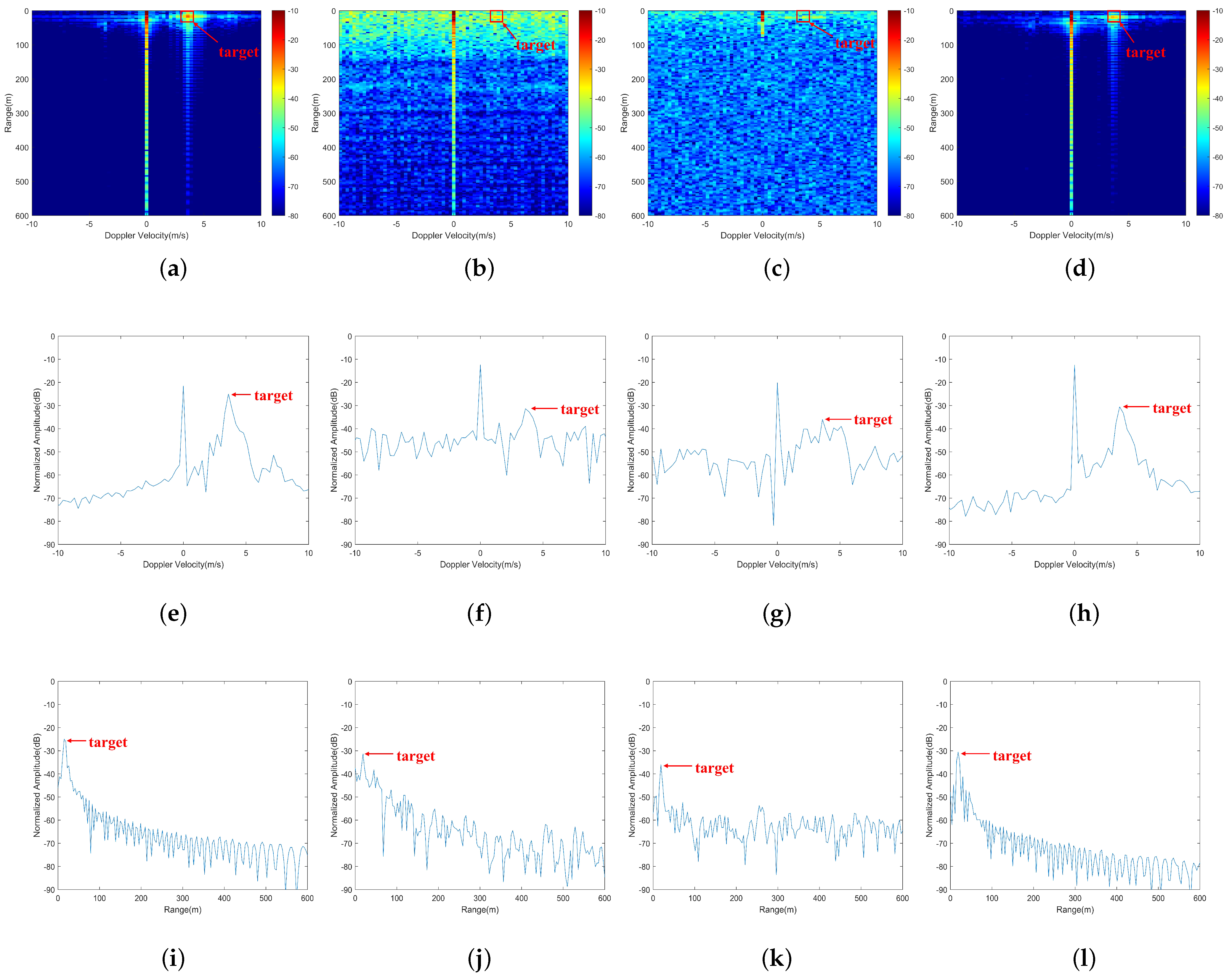
When verifying the detection effect of the integrated waveform, a running person was chosen as the moving target, moving from right to left. The integrated system A was placed on the left side of the scene (as depicted in Figure 8) to emit radar signals for detecting the person approaching from the right side. Various types of signals were used for transmission, including LFM signals, traditional integrated signals based on smart modulation, traditional NFM integrated signals, and the proposed integrated signals. The echoes were processed accordingly. The detection results of the selected data were all in the same range, ensuring that the strength of the moving target remained the same, thus guaranteeing the accuracy of subsequent analysis. The results are shown in Figure 9. The LFM signal exhibits excellent detection performance with low sidelobes in the range-Doppler map, and both the range profile and velocity profile sidelobes where the target is located are also low. In contrast, the traditional integrated signal based on smart modulation has higher overall sidelobes, and especially higher sidelobes closer to the target in the range profile, posing a risk of false targets, resulting in ordinary detection performance. Similarly, the traditional NFM integrated signal shows a higher overall sidelobe, almost masking the targets in the velocity profile with sidelobes, leading to ordinary detection performance. On the other hand, the detection performance of the proposed integrated signal is close to that of the LFM signal, demonstrating good detection capability. In experimental measurements, noise and clutter are the primary interference factors. The quality of detection results can be described using the signal-to-clutter-noise ratio (SCNR). In the range-Doppler maps, SCNR can be calculated as the ratio of the target’s main peak to the mean energy of clutter and noise in the surrounding cells. The SCNR for different emitted signal detection results are shown in Table 3. The proposed integrated signal enhances detection performance through waveform complementarity. Compared to traditional integrated signals based on smart modulation and traditional NFM integrated signals, it improves the SCNR by 26.83 dB and 32.38 dB, respectively. While ensuring the jamming effect, the SCNR of the proposed integrated signal is close to that of the LFM signal, differing by only 6.04 dB. Therefore, this integrated waveform demonstrates good detection performance.
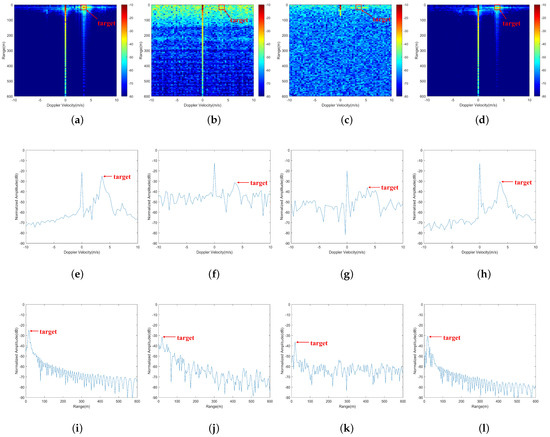
Figure 9.
The range-Doppler maps: (a) LFM signal, (b) traditional integrated signal based on smart modulation, (c) traditional NFM integrated signal, and (d) the proposed integrated signal. The Doppler profiles at the target location, as shown in (e) Figure 9 (a), (f) Figure 9 (b), (g) Figure 9 (c), and (h) Figure 9 (d). The range profile at the target location is shown in (i) Figure 9 (a), (j) Figure 9 (b), (k) Figure 9 (c), and (l) Figure 9 (d).
Table 3.
SCNR of different emitted signal detection results.
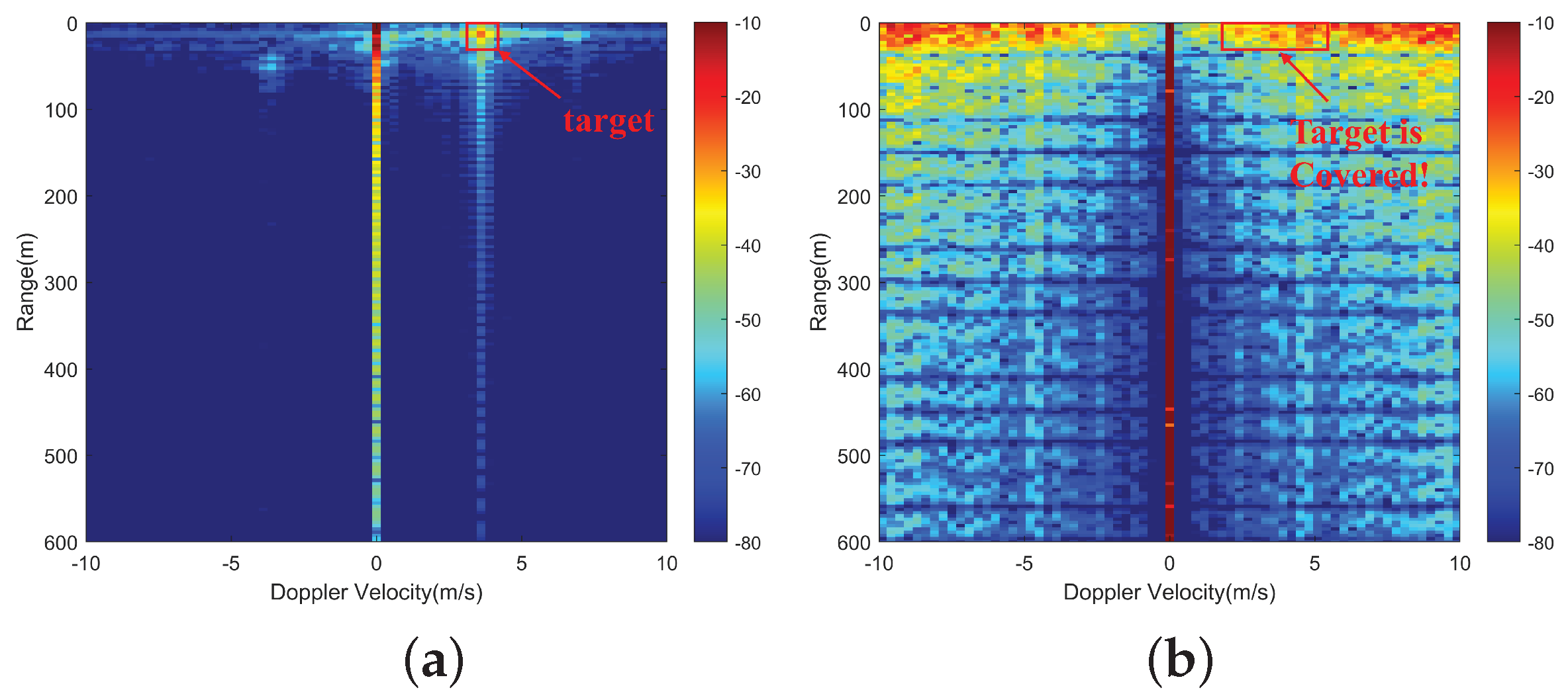
When verifying the jamming effect of the integrated waveform, a running person was chosen as the moving target, moving from right to left. Integrated system A was placed on the left side of the scene (as depicted in Figure 8) to emit LFM signals for detecting the person approaching from the right side. Integrated system B was placed near system A to emit the proposed integrated signal to interfere with system A. Both system A and system B had the same signal transmission power. The comparison before and after jamming is shown in Figure 10. After the jamming caused by the proposed integrated signal, the target on the range-Doppler map of the LFM signal was almost covered, indicating that this integrated signal could effectively interfere with the radar detection of the adversary’s system.

Figure 10.
The range-Doppler maps: (a) LFM signal, (b) LFM signal after jamming from the proposed integrated signal.
8. Conclusions
This paper proposes an integrated radar and jamming waveform based on smart modulation and complementary coding. It combines the characteristics of traditional integrated radar and jamming signals based on smart modulation and the advantages of LFM signal in detection. By adjusting the phase angle of the binary phase coding sequence and utilizing the inter-pulse complementarity, it can achieve ideal detection and jamming effects. The limitations of this waveform include its Doppler sensitivity, where the sidelobes will significantly increase with the target velocity, a certain loss of SNR, which occurs when synthesizing the complete LFM signal through complementary adjacent pulses, and adjacent pulses complementation, which reduces the pulse repetition frequency of the signal, thereby also reducing the maximum unambiguous velocity during detection. Simulation analysis shows that when the target velocity is below a certain value, the detection performance of the proposed integrated waveform is better than the traditional integrated waveform, and the proposed integrated waveform can flexibly adjust detection and jamming performance by adjusting the phase angle of the binary phase-coded sequence. Experimental results demonstrate that the proposed integrated signal, using complementary processing, can achieve better detection performance compared to traditional integrated signals based on smart modulation and traditional NFM integrated signals. Additionally, its detection effect approaches that of traditional LFM signals. Moreover, this waveform can effectively interfere with the radar detection of adversaries’ systems.
Author Contributions
Conceptualization, X.L. and H.Y.; methodology, H.Y.; software, H.Y.; validation, H.Y., S.Z. and L.D.; formal analysis, X.L. and J.Y.; investigation, K.T.; resources, H.G.; data curation, H.Y.; writing—original draft preparation, H.Y.; writing—review and editing, H.Y. and S.Z.; visualization, X.L.; supervision, X.L.; project administration, X.L.; funding acquisition, X.L. All authors have read and agreed to the published version of the manuscript.
Funding
This research was funded in part by the National Natural Science Foundation of China under Grant 62001229, Grant 62101264, and Grant 62101260; in part by the Natural Science Foundation of Jiangsu Province under Grant BK20210334 and Grant BK20230915; in part by the China Postdoctoral Science Foundation under Grant 2020M681604; and in part by the Jiangsu Province Postdoctoral Science Foundation under Grant. 2020Z441.
Data Availability Statement
Data are contained within the article.
Conflicts of Interest
The authors declare no conflicts of interest.
Abbreviations
The following abbreviations are used in this manuscript:
| LFM | linear frequency modulation |
| EW | electronic warfare |
| NFM | noise frequency modulation |
| SNR | signal-to-noise ratio |
| MTD | moving target detection |
| CPI | coherent processing interval |
| PRI | pulse repetition interval |
| ISLR | integration sidelobe ratio |
| USRP | universal software radio peripheral |
| RF | radio frequency |
| SCNR | signal-to-clutter-noise ratio |
References
- Zhang, C.; Wang, L.; Jiang, R.; Hu, J.; Xu, S. Radar jamming decision-making in cognitive electronic warfare: A review. IEEE Sens. J. 2023, 23, 11383–11403. [Google Scholar] [CrossRef]
- Liu, G.; Huang, Z.; Zhang, Q.; Mu, B.; Guo, H. Joint Radar Jamming and Communication System Design Based on Universal Filtered Multicarrier Chirp Waveform. Remote Sens. 2024, 16, 1383. [Google Scholar] [CrossRef]
- Wang, Y.; Cao, Y.; Yeo, T.S.; Cheng, Y.; Fu, J. Robust Multiplexing Waveform Design for Integrated OFDM Radar and Communication via Complex Weight Optimization. Remote Sens. 2023, 15, 4438. [Google Scholar] [CrossRef]
- Zhang, L.; Luo, Y.; Wang, H.; Zhang, Q. Detection of False Targets in a Full Polarization Radar Network under Deception Jamming. IEEE Sens. J. 2023, 24, 3368–3379. [Google Scholar] [CrossRef]
- Xu, C.; Chen, T. Conception of “signal sharing” in integrated radar and jammer system and the integrated signal design. In Proceedings of the IEEE 2002 International Conference on Communications, Circuits and Systems and West Sino Expositions, Chengdu, China, 29 June–1 July 2002; IEEE: New York, NY, USA, 2002; Volume 1, pp. 502–505. [Google Scholar] [CrossRef]
- Zhang, X.; Chen, T. Noise-linear frequency modulation shared waveform for integrated radar and jammer system. In Proceedings of the 2007 International Conference on Communications, Circuits and Systems, Kokura, Japan, 11–13 July 2007; IEEE: New York, NY, USA, 2007; pp. 644–648. [Google Scholar] [CrossRef]
- Han, G.; He, J.; Qi, J. An Optimization Design Method of Integrated Radar and Jammer Signal Modulated by Bi-phase Sequences of Chaos. In Proceedings of the 2012 Eighth International Conference on Computational Intelligence and Security, Guangzhou, China, 17–18 November 2012; IEEE: New York, NY, USA, 2012; pp. 44–47. [Google Scholar] [CrossRef]
- Shi, Q.; Wu, S.; Huang, J.; Wang, C.; Yuan, N. A novel jamming method against LFM radar using pseudo-random code phase modulation. In Proceedings of the 2017 IEEE International Conference on Signal Processing, Communications and Computing (ICSPCC), Xiamen, China, 22–25 October 2017; IEEE: New York, NY, USA, 2017; pp. 1–5. [Google Scholar] [CrossRef]
- Li, C.; Wu, G. A Shared Waveform Design and Processing Method for Integrated Radar Detection and Coherent Jamming Signal. In Proceedings of the 2022 IEEE 10th Joint International Information Technology and Artificial Intelligence Conference (ITAIC), Chongqing, China, 17–19 June 2022; IEEE: New York, NY, USA, 2022; Volume 10, pp. 373–380. [Google Scholar] [CrossRef]
- Li, C.; Wu, G.; Li, G. A Shared Waveform Design for Integrated Detection and Jamming Signal Based on LFM-Costas Intra-pulse Frequency Stepping. In Proceedings of the 2022 7th International Conference on Communication, Image and Signal Processing (CCISP), Chengdu, China, 18–20 November 2022; IEEE: New York, NY, USA, 2022; pp. 347–354. [Google Scholar] [CrossRef]
- Zhang, S.; Lu, X.; Yu, J.; Dai, Z.; Su, W.; Gu, H. Clutter Suppression for Radar via Deep Joint Sparse Recovery Network. IEEE Geosci. Remote Sens. Lett. 2024, 21, 3332035. [Google Scholar] [CrossRef]
- Ackroyd, M.H.; Ghani, F. Optimum mismatched filters for sidelobe suppression. IEEE Trans. Aerosp. Electron. Syst. 1973, AES-9, 214–218. [Google Scholar] [CrossRef]
- Griep, K.R.; Ritcey, J.A.; Burlingame, J.J. Poly-phase codes and optimal filters for multiple user ranging. IEEE Trans. Aerosp. Electron. Syst. 1995, 31, 752–767. [Google Scholar] [CrossRef]
- Levanon, N.; Scharf, A. Range sidelobes blanking using contrasting mismatched filters. In Proceedings of the 2009 16th International Conference on Digital Signal Processing, Santorini, Greece, 5–7 July 2009; IEEE: New York, NY, USA, 2009; pp. 1–6. [Google Scholar] [CrossRef]
- Kajenski, P.J. Mismatch filter design via convex optimization. IEEE Trans. Aerosp. Electron. Syst. 2016, 52, 1587–1591. [Google Scholar] [CrossRef]
- Fridman, L.; Ershov, G.; Myasnikov, S.; Sinitsin, E. Compression of phase-shift keyed signals by means of the mismatched sidelobe-free filter with application to coherent pulse radar. In Proceedings of the 2017 18th International Radar Symposium (IRS), Prague, Czech Republic, 28–30 June 2017; IEEE: New York, NY, USA, 2017; pp. 1–10. [Google Scholar] [CrossRef]
- Kempf, J.; Jackson, J.A. A modified least-squares mismatched filter for use in radar applications with additive noise. In Proceedings of the 2020 IEEE International Radar Conference (RADAR), Washington, DC, USA, 28–30 April 2020; IEEE: New York, NY, USA, 2020; pp. 804–809. [Google Scholar] [CrossRef]
- Golay, M. Complementary series. IRE Trans. Inf. Theory 1961, 7, 82–87. [Google Scholar] [CrossRef]
- Li, J.; Liu, Y.; Xu, H.; Wang, B.; Liu, L.; Chen, X. A high signal–noise ratio UWB radar for buried pipe location using golay complementary sequences. Appl. Sci. 2019, 9, 5090. [Google Scholar] [CrossRef]
- Chen, H.; Yuan, K.; Yao, M.; Xiong, J. A Novel Composite Coding Method for Incoherent Scatter Radar. Atmosphere 2021, 12, 1518. [Google Scholar] [CrossRef]
- Song, Y.; Wang, Y.; Xie, J.; Yang, Y.; Tian, B.; Xu, S. Ultra-low sidelobe waveforms design for LPI radar based on joint complementary phase-coding and optimized discrete frequency-coding. Remote Sens. 2022, 14, 2592. [Google Scholar] [CrossRef]
- Wu, Z.J.; Wang, C.X.; Jiang, P.H.; Zhou, Z.Q. Range-Doppler sidelobe suppression for pulsed radar based on Golay complementary codes. IEEE Signal Process. Lett. 2020, 27, 1205–1209. [Google Scholar] [CrossRef]
- Lan, L.; Xu, J.; Liao, G.; Zhang, Y.; Fioranelli, F.; So, H.C. Suppression of mainbeam deceptive jammer with FDA-MIMO radar. IEEE Trans. Veh. Technol. 2020, 69, 11584–11598. [Google Scholar] [CrossRef]
- Zhang, S.; Lu, X.; Yang, J.; Su, W.; Gu, H. Enhanced Signal Processing Method for Integrated Detection and Jamming System Considering the Complex Environment. In Proceedings of the 2021 CIE International Conference on Radar (Radar), Haikou, China, 15–19 December 2021; IEEE: New York, NY, USA, 2021; pp. 2233–2237. [Google Scholar] [CrossRef]
- Lang, P.; Fu, X.; Dong, J.; Yang, J. An efficient radon Fourier transform-based coherent integration method for target detection. IEEE Geosci. Remote Sens. Lett. 2023, 20, 1–5. [Google Scholar] [CrossRef]
- Azouz, A.; Abosekeen, A.; Nassar, S.; Hanafy, M. Design and implementation of an enhanced matched filter for sidelobe reduction of pulsed linear frequency modulation radar. Sensors 2021, 21, 3835. [Google Scholar] [CrossRef] [PubMed]
- Li, X.; Yang, Y.; Sun, Z.; Cui, G.; Yeo, T.S. Multi-frame integration method for radar detection of weak moving target. IEEE Trans. Veh. Technol. 2021, 70, 3609–3624. [Google Scholar] [CrossRef]
- Zhang, X.; Su, D.; Zhou, M. The analysis and simulation research of distance resolution and ambiguity property of LFM signal. In Proceedings of the 2007 International Symposium on Microwave, Antenna, Propagation and EMC Technologies for Wireless Communications, Hangzhou, China, 14–17 August 2007; IEEE: New York, NY, USA, 2007; pp. 1191–1194. [Google Scholar] [CrossRef]
- Levanon, N.; Mozeson, E. Coherent Train of LFM Pulses. In Radar Signals; Wiley: Hoboken, NJ, USA, 2004; pp. 168–190. [Google Scholar] [CrossRef]
- Lan, L.; Marino, A.; Aubry, A.; De Maio, A.; Liao, G.; Xu, J.; Zhang, Y. GLRT-based adaptive target detection in FDA-MIMO radar. IEEE Trans. Aerosp. Electron. Syst. 2020, 57, 597–613. [Google Scholar] [CrossRef]
- Liu, Y.; Zhang, H.; Wang, X.; Dong, Q.; Lyu, X. An Improved Multi-Frame Coherent Integration Algorithm for Heterogeneous Radar. Remote Sens. 2023, 15, 4026. [Google Scholar] [CrossRef]
- Gao, Y.; Hua, Y.; Li, S.; Yang, C. Acquisition method of Loran-C signal based on matched filter. In Proceedings of the 2015 IEEE International Conference on Signal Processing, Communications and Computing (ICSPCC), Ningbo, China, 19–22 September 2015; IEEE: New York, NY, USA, 2015; pp. 1–5. [Google Scholar] [CrossRef]
- Wang, H.; Hu, T.; Li, T.; Wu, D.; Xu, Z.; Xu, X.; Tian, Z. Intelligent Interference Waveform Design for Radar Detection based on Cross-Correlation Value Function. IEEE Trans. Aerosp. Electron. Syst. 2023, 60, 2061–2070. [Google Scholar] [CrossRef]


Disclaimer/Publisher’s Note: The statements, opinions and data contained in all publications are solely those of the individual author(s) and contributor(s) and not of MDPI and/or the editor(s). MDPI and/or the editor(s) disclaim responsibility for any injury to people or property resulting from any ideas, methods, instructions or products referred to in the content. |
© 2024 by the authors. Licensee MDPI, Basel, Switzerland. This article is an open access article distributed under the terms and conditions of the Creative Commons Attribution (CC BY) license (https://creativecommons.org/licenses/by/4.0/).