Communication

Cascade Clutter Suppression Method for Airborne Frequency Diversity Array Radar Based on Elevation Oblique Subspace Projection and Azimuth-Doppler Space-Time Adaptive Processing

School of Electronics and Communication Engineering, Sun Yat-sen University, Shenzhen 518107, China
*
Author to whom correspondence should be addressed.
Remote Sens. 2024, 16(17), 3198; https://doi.org/10.3390/rs16173198
Submission received: 1 August 2024 / Revised: 23 August 2024 / Accepted: 28 August 2024 / Published: 29 August 2024
(This article belongs to the Section Remote Sensing Communications)

Abstract

:
Airborne Frequency Diversity Array (FDA) radar operating at a high pulse repetition frequency encounters severe range-ambiguous clutter. The slight frequency increments introduced by the FDA result in angle and range coupling. Under these conditions, conventional space-time adaptive processing (STAP) often exhibits diminished performance or fails, complicating target detection. This paper proposes a method combining elevation oblique subspace projection with azimuth-Doppler STAP to suppress range-ambiguous clutter. The method compensates for the quadratic range dependence by analyzing the relationship between elevation frequency and range. It uses an elevation oblique subspace projection technique to construct an elevation adaptive filter, which separates clutter from ambiguous regions. Finally, residual clutter suppression is achieved through azimuth-Doppler STAP, enhancing target detection performance. Simulation results demonstrate that the proposed method effectively addresses range dependence and ambiguity issues, improving target detection performance in complex airborne FDA radar environments.

1. Introduction

Forward-looking airborne radar encounters intense ground clutter during downward surveillance, where the varying speeds caused by aircraft movement result in significant Doppler frequency extension, complicating target detection [1,2,3]. Space-time adaptive processing (STAP) [4] is a highly effective technique used in airborne radar for clutter suppression. STAP combines spatial information from the array and temporal information from a pulse to identify and filter out unwanted signals, allowing the radar to focus on detecting targets of interest [5,6,7]. By adaptively adjusting the processing parameters in response to the changing environment, STAP can effectively mitigate the impact of ground clutter and other sources of interference and finally enhance the radar’s ability to detect and track moving targets. STAP’s effectiveness has made it a crucial component in modern airborne radar systems, improving their performance and reliability in both military and civilian applications. Nevertheless, a significant challenge in STAP is the estimation of the clutter covariance matrix (CCM), which requires a substantial number of independent and identically distributed (IID) training samples [8,9]. When operating at a high pulse repetition frequency (HPRF), airborne radar is frequently confronted with the challenge of range-ambiguous clutter. Under these circumstances, many existing compensation methods are ineffective.
In a phased array (PA) system, short-range clutter, termed non-stationary clutter, has an elevation spatial frequency that varies significantly with range. In contrast, the elevation spatial frequency of stationary clutter, or far-range clutter, tends to remain relatively constant [10,11]. Non-stationarity has a considerable influence on the accuracy of CCM estimation, and contributes to an increase in the degrees of freedom (DOFs) of clutter. The decline in the efficacy of clutter suppression has the potential to impede the accurate identification of targets, thereby compromising the overall performance of the radar system and increasing the risk of missed detection or false alarm.
One effective approach to suppress non-stationary clutter is to utilize three-dimensional STAP; in this method, an adaptive filter is applied in elevation before the estimation of the CCM in azimuth [12,13]. This method leverages the elevation dimension to better mitigate clutter effects, enhancing the radar’s ability to distinguish between targets and clutter. However, performance can degrade when elevation DOFs are limited, as these methods may not fully capture the complex characteristics of the clutter. To address this, an elevation-compensation technique has been proposed in [14], while effective for near-range clutter from the first pulse, its performance diminishes when subsequent pulses also encounter near-range clutter, particularly under HPRF conditions.
The concept of the frequency diverse array (FDA) has garnered significant attention from researchers worldwide since its introduction [15]. The frequency increment employed by the airborne FDA radar is specifically designed to suppress clutter and enhance target detection. By introducing a small frequency difference between each element, FDA effectively separates clutter from different ranges by exploiting variations in the transmitted carrier frequency. This technique improves clutter suppression by distinguishing signals reflected from various ranges. One notable application of FDA is detailed in [16], where frequency increments are applied to uniform linear arrays to suppress range-ambiguous clutter. However, its effectiveness is constrained by the finite number of ambiguities, which can make it difficult to fully address practical requirements.
Further advancements are discussed in [17,18], where a slight frequency increment is introduced in the elevation dimension. This method extends the spatial elevation frequency, helping to suppress range-ambiguous clutter by expanding elevation frequency intervals across different ambiguous regions. Despite its potential, the complexity and practical implementation of this approach present significant challenges. Recent studies [17,18,19] explore techniques such as spatial filtering and advanced coding strategies to further address range-ambiguous clutter. These studies offer innovative perspectives on clutter suppression, presenting novel approaches to tackling the challenges of range ambiguity in practical radar systems.
This paper presents a cascade method that combines elevation filtering with azimuth-Doppler STAP to suppress range-ambiguous clutter in airborne FDA radars. Specifically, it utilizes quadratic range-dependence compensation to address the coupling issue between elevation frequency and range in FDA radars. After compensating, elevation frequencies across different range regions are effectively separated. To extract the desired signal components from the compensated echo signal and estimate the elevation matrix, it is necessary to project the received signal onto the subspace spanned by the undesired signal components, employing an oblique projection matrix. Subsequently, an elevation-adaptive filter is devised to separate range-ambiguous clutter in disparate regions. Finally, the conventional azimuth-Doppler STAP is employed to suppress the clutter within the extracted signal. The following is a description of the organization of the paper: Section 2 presents the signal model for the airborne FDA radar. Section 3 provides a detailed account of the proposed method. Section 4 presents the results of simulations conducted to validate the effectiveness of the proposed method. Section 5 concludes with a summary of the paper’s findings.

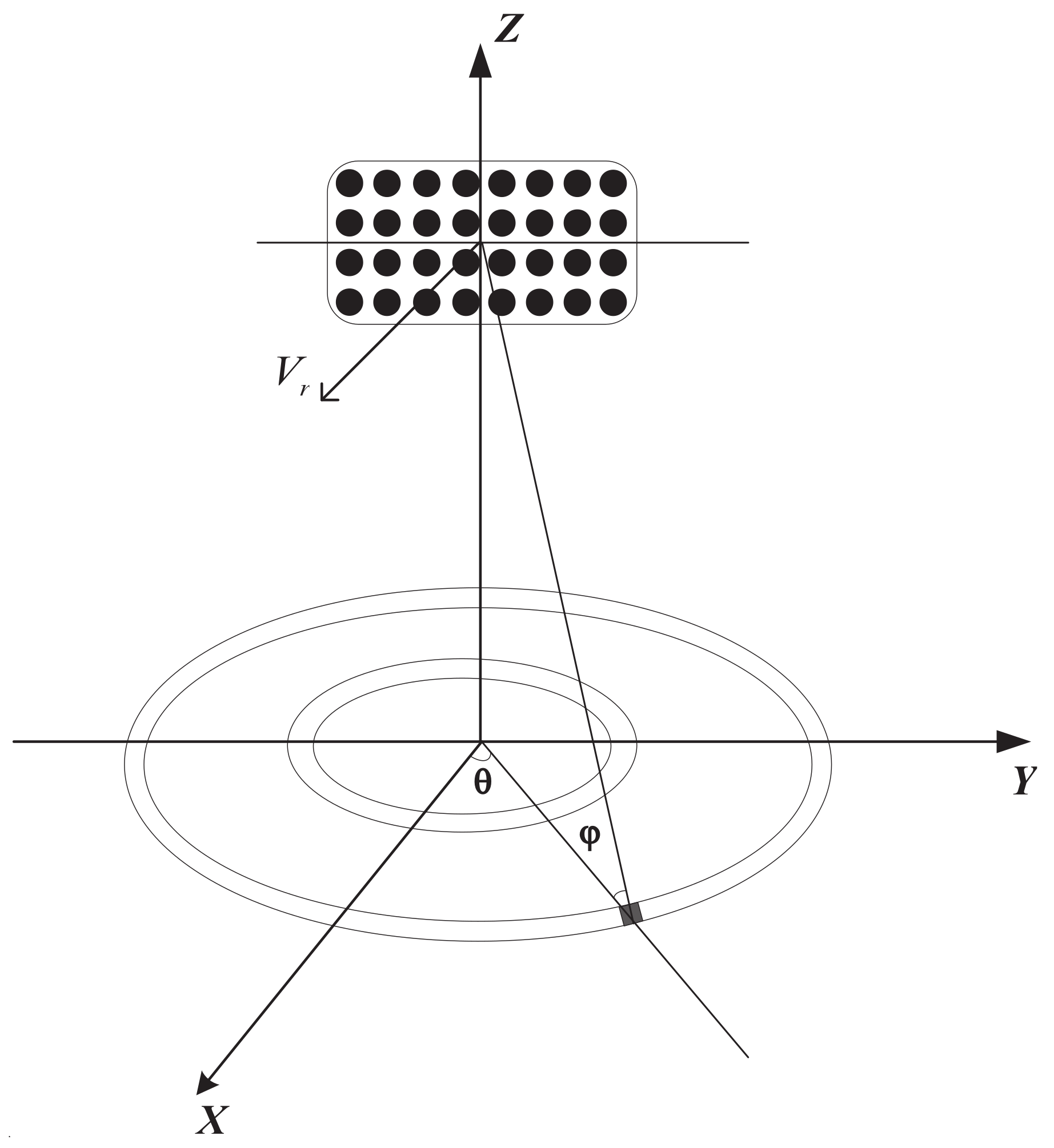
2. Signal Model of Airborne FDA Radar

In this paper, we consider a forward-looking airborne FDA radar, as depicted in Figure 1, operating at a HPRF. The airborne FDA radar system is configured with K pulses within a coherent processing interval (CPI). The pulse repetition frequency is designated as f r . The altitude of the airborne FDA radar platform is designated as H, while its flight speed is represented by V r . The radar’s array is a uniform planar array, and comprises a total of M N elements, where M , N denotes the number of elements in the row and column directions, respectively. Let us assume that the position of a ground clutter block is located at the coordinates θ , φ , where the azimuth angle, denoted by the symbol θ , and the elevation angle, represented by the symbol ϕ , are the angles of the ground clutter block.
In the airborne FDA configuration, the transmit carrier frequency varies across rows but remains the same within each column. Let f 0 be the reference carrier frequency; the transmit carrier frequency of the m-th row element can be expressed as
f m = f 0 + ( m 1 ) Δ f m = 1 , 2 , , M
where Δ f is the frequency increment, which is much smaller than f 0 .
The received signal corresponding to the l-th range gate, which includes clutter, the target signal, and noise, can be expressed as
x l = s + c l + n l
where s , c l , and n l represent the target vector, clutter vector, and noise vector, respectively.
According to the clutter model mentioned in [20], the clutter vector received by the l-th range gate is represented as
c l = i = 1 N r j = 1 N c ξ l i j s t θ l i j , φ l i s a θ l i j , φ l i ( s e φ l i s r φ l i )
where ξ l i j represents the complex scattering amplitude of the jth clutter block within i-th ambiguous zone corresponding to the l-th range gate. N R is the number of range ambiguities, and N C is the number of clutter sources of a range ring. c l represents M N K × 1 clutter vector corresponding to the l-th range gate. For a single clutter block on a range ring, s t θ l i j , φ l i represents the temporal steering vector; s a θ l i j , φ l i and s e φ l i represent spatial azimuth and elevation steering vector; s r φ l i represent the spatial range steering vector. They can be derived as follows [17]:
s a θ l i j , φ l i = 1 , e j 2 π f a θ l i j , φ l i , , e j 2 π N 1 f a θ l i j , φ l i T
s e φ l i = 1 , e j 2 π f e φ l i , , e j 2 π M 1 f e φ l i T
s r φ l i = 1 , e j 2 π f r φ l i , , e j 2 π ( M 1 ) f r φ l i T
s t θ l i j , φ l i = 1 , e j 2 π f t θ l i j , φ l i , , e j 2 π K 1 f t θ l i j , φ l i T
where f a ( θ l i j , φ l i ) represents the spatial azimuth frequency, f e ( φ l i ) represents spatial elevation frequency, f r ( φ l i ) represents spatial elevation range frequency, and f t ( θ l i j , φ l i ) represents normalized Doppler frequency. They can be expressed as
f a ( θ l i j , φ l i ) = d cos θ l i j cos φ l i λ
f e ( φ l i ) = d sin φ l i λ
f r ( φ l i ) = 2 R Δ f c
f t ( θ l i j , φ l i ) = 2 V r sin θ l i j cos φ l i λ f r
where R represents the slant range. Considering the curvature of the Earth, the relationship between φ l i and R can be approximately expressed as follows:
φ l i = arcsin ( H R + R 2 R m a x )
where R m a x = 2 H R e represents the maximum detectable range of the airborne FDA radar, and R e is the radius of the Earth. Equation (10) indicates that the elevation angle is related to the slant range and platform height.
The steering vector of the target signal s can be expressed as
s = ξ t s t φ t , θ t s a φ t , θ t ( s e φ t s r φ t )
where ξ t is the complex scattering amplitude of the target signal, and s t φ t , θ t , s a φ t , θ t , s e φ t , and s r φ t represent the temporal steering vector, spatial azimuth steering vector, spatial elevation steering vector, and spatial range steering vector for the target, respectively.

3. The Proposed Method

In this section, we describe the cascade method for suppressing range-ambiguous clutter in airborne FDA radar, utilizing elevation oblique subspace projection and azimuth-Doppler STAP. To address the coupling between elevation frequency and range, FDA quadratic range dependence compensation, which mitigates the issue of frequency and range interaction, is introduced in Section 3.1. To achieve effective separation of clutter in different regions, the elevation oblique subspace projection technique and the design of the elevation adaptive filter are introduced in Section 3.2. To further suppress residual clutter and improve overall performance, azimuth-Doppler STAP is introduced in Section 3.3. This approach refines the clutter suppression process, addressing any remaining clutter components after the initial filtering stages.

3.1. The FDA Quadratic Range Dependence Compensation

For clutter blocks in different ambiguous regions, the spatial frequency and the slant range are as follows:
f s ( φ l i ) = f e ( φ l i ) f r ( φ l i ) = d λ sin φ l i 2 Δ f R c
R = R l + ( p 1 ) R u
where p is the the index of the different ambiguous regions, R l is the principal sampling range and R u is the maximum unambiguous range. We can derive the following:
f s ( φ l i ) = d λ sin φ l i 2 Δ f R l c 2 Δ f ( p 1 ) R u c
With the specified compensation frequency being f r c ( R l ) = 2 Δ f R l c , the elevation spatial frequency is represented as
f ˜ s ( φ l i ) = f s ( φ l i ) + f r c ( R l ) = d λ sin φ l i 2 Δ f ( p 1 ) R u c
In the PA, the elevation frequency occupies the positive frequency range from 0 to 0.5, as shown in Figure 2a. In the FDA radar system, the spatial frequency extends from positive to negative values, allowing the separation of elevation frequencies from each range ambiguous region within the spatial domain. At the same time, Equation (16) indicates that the uncompensated elevation spatial frequency f s ( φ l i ) is not only related to R u and the index of the ambiguous region p, but also to the principal sampling range R l , as shown in Figure 2b. Equation (17) shows that the uncompensated elevation spatial frequency f ˜ s ( φ l i ) is only related to the maximum unambiguous range R u and the index of the ambiguous region p, as illustrated in Figure 2c.

3.2. Oblique Subspace Projection and Separation of Clutter across Different Range Ambiguous Regions

In radar systems, especially in complex scenarios involving clutter and noise, oblique subspace projection can help improve signal detection and separation. Assuming that the received signal has N r range ambiguity, we are expected to extract the N t range ambiguous signal. Here, we define the clutter in the ambiguous region we hope to extract as desired clutter, while the clutter we do not hope to extract is defined as undesired clutter. The received signal of the l-th range gate after compensation can be represented by
x l c = x l , 1 c + + x l , N t c + + x l , N r c
Equation (18) shows that the compensated received signal comprises different elevation frequency components. As analyzed in Section 3.1, the elevation frequencies in different ambiguous regions are clearly distinguished. After compensation, the elevation spatial steering vector is
s c p e = 1 , e j 2 π f ˜ s ( φ l i ) , , e j 2 π ( M 1 ) f ˜ s ( φ l i ) T
We expect the elevation adaptive pattern to point to the desired clutter region while forming nulls in undesired regions. This indicates that the elevation covariance matrix should contain undesired clutter components while removing desired ones. Based on the above analysis, this paper proposes an elevation oblique subspace projection [21] method. The elevation oblique projection matrix of the l-th range gate can be represented as
P l = H u d H u d H H d H u d 1 H u d H H d
where H n d C M × ( N r 1 ) , H d C M × 1 , H d C M × M represent the spatial steering matrix for undesired clutter, the spatial steering vector for desired clutter and orthogonal projector.
H n d = s e 1 c , , s e ( N t 1 ) c , s e ( N t + 1 ) c , , s e N r c
H d = s e N t c
H d = I H d H d H H d 1 H d H
After oblique subspace projection processing, it allows for better separating of clutter by projecting the signals onto a subspace that is tailored to the specific characteristics of the radar signals. The estimated elevation covariance matrix can be formulated as
R l = P l · mat ( x l c ) P l · mat ( x l c ) H N K
where mat ( x l c ) C M × N K is the clutter echo matrix corresponding to the l-th range gate. We can design the elevation adaptive weighting vector for pre-filtering using the following constraints:
min w e w e H R l w e s . t . C H w e = f
where C = [ s e 1 c , s e 2 c , , s e N t c , , s e N r c ] C M × N r , f = [ 0 , , 1 , , 0 ] H C N r × 1 represent space-time steering matrix and constraint vector, respectively. The solution to  (25) is easily calculated by
w e = R l 1 C C H R l 1 C 1 f
After elevation oblique subspace projection and filtering processing, the echo signal can be expressed as
x ˜ l = w e H mat ( x l c )
where x ˜ l C 1 × N K represents the signal after elevation filtering. To emphasize the advantages of the proposed method, the improved conventional beamforming (CBF) filter is specifically designed to achieve high gain exclusively in the desired clutter region.
w c b f = H d
There are some differences between the improved CBF method and the CBF method processing. The CBF method is obtained by synthesizing the elevation main beam center across all range gates in the elevation dimension, where each range gate’s elevation weight vector is
w e 0 = 1 , e j 2 π f ˜ s 0 ( φ 0 ) , , e j 2 π ( M 1 ) f ˜ s 0 ( φ 0 ) T
where
f ˜ s 0 ( φ 0 ) = = d λ 0 sin φ 0 2 Δ f ( N t 1 ) R u c
The improved CBF method calculates the elevation filter vector for each range gate, where each range gate’s elevation steering vector is shown in Equation  (28).

3.3. Residual Clutter Suppression

After pre-filtering in the elevation, undesired clutter is effectively suppressed. Traditional azimuth-Doppler STAP can then address the remaining clutter for further suppression. This process ensures that the radar system can effectively manage and mitigate residual clutter after elevation filtering, leading to improved overall performance. Typically, adjacent range gates are used as training samples to estimate the actual CCM by
R ˜ = 1 L l = 1 L x ˜ l H x ˜ l
Here, L represents the number of training samples. To ensure the average performance loss is less than 3 dB, L must be more than twice the DOFs. Finally, the azimuth-Doppler STAP steering vector is
w 0 = R ˜ 1 s 0 s 0 R ˜ 1 s 0
where s 0 = s t 0 s a 0 represents the target’s steering vector. According to azimuth-Doppler STAP, the final output can be obtained as
y l = w 0 H x ˜ l
In summery, the signal processing procedure of clutter separation and suppression are shown in Algorithm 1.
Algorithm 1 The procedure of clutter separation and suppression
 1: Load airborne FDA radar echo signal.
 2: for l-th range gate:
 3: Calculate ϕ l i according to Equation (12);
 4: Calculate the compensation frequency f r c ( R l ) = 2 Δ f R l c to compensate for the elevation frequency of the received signal.
 5: Calculate the compensated elevation spatial steering vector by Equation (19);
 6: Construct the elevation oblique projection matrix by Equation (20);
 7: Calculate the elevation filtering weight vector by Equation (26); carry out the range-ambiguous clutter suppression according to Equation (27).
 8: end
 9: Estimate the CCM according to Equation (31);
10: Calculate the azimuth-Doppler STAP steering vector by Equation (32) and suppress residual clutter by Equation (33).

4. Results and Discussion

This section presents simulation experiments to validate the effectiveness of the proposed method. The parameters for the forward-looking airborne FDA radar simulation are provided in Table 1.

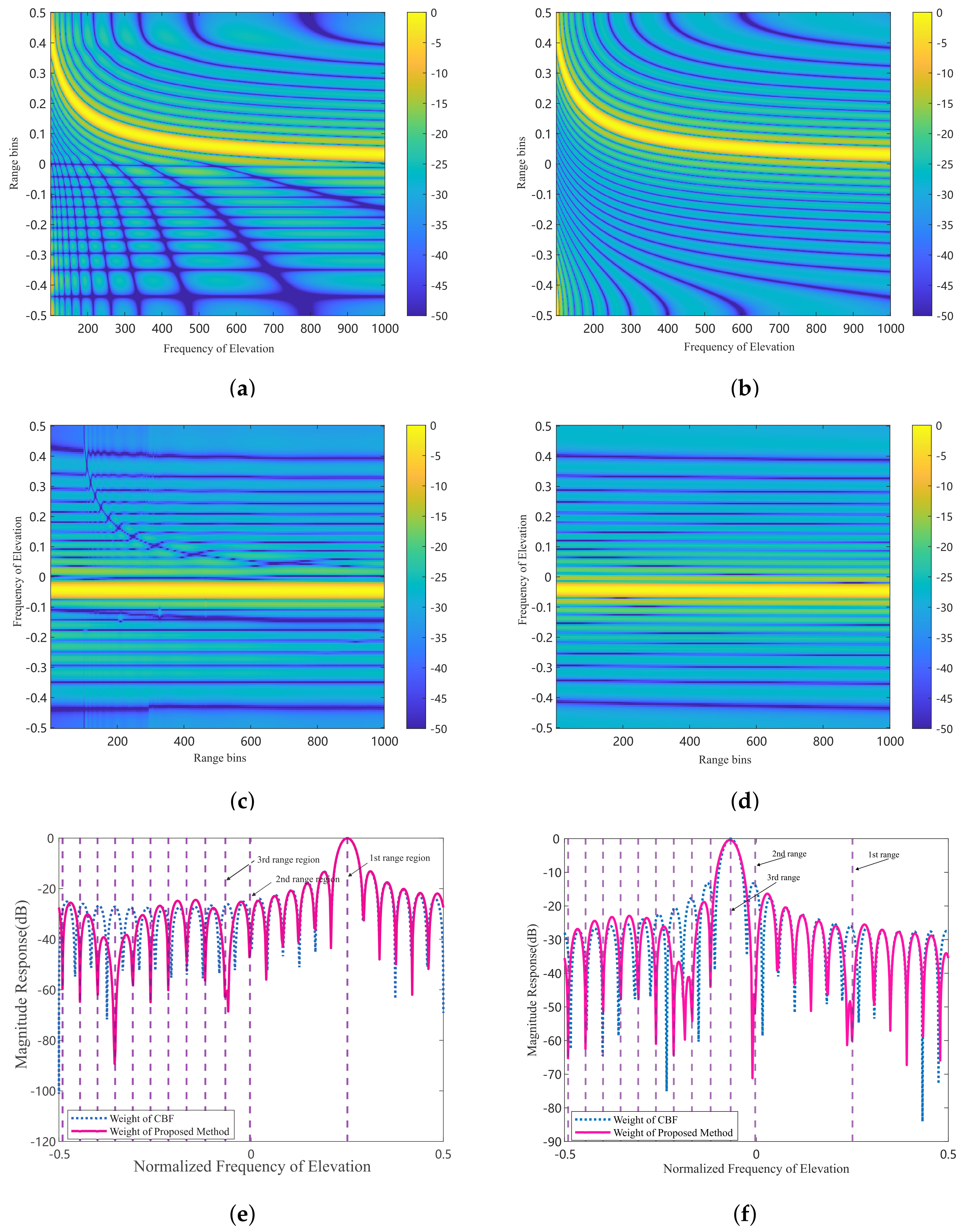
4.1. Beam Response Pattern

The first experiment compares the beam response of the proposed method with the CBF method. Given the weight vector produced by the elevation filter, its response as a function of elevation frequency is one indicator of the processor’s performance. This response is called the beam response pattern, defined by
P w ( f e ) = w e H s e ( f e )
where s e ( f e ) is a function of elevation frequency.
Considering the extraction of clutter in the first ambiguous region, as shown in Figure 3a, the proposed method achieves a high gain at the elevation frequency corresponding to the clutter in this region while forming nulls for clutter in other ambiguous regions. This selective gain ensures that clutter from the first ambiguous region is effectively extracted. In contrast, as shown in Figure 3b, the improved CBF method only achieves high gain at the elevation frequency corresponding to the clutter in the first ambiguous region, and does not form nulls at the elevation frequencies corresponding to clutter in other ambiguous regions. This lack of null formation means that the CBF method is less effective at suppressing clutter from other regions, which can lead to degraded performance in target detection.
Let us consider clutter extraction in the third ambiguous region as an example. Figure 3c shows the beam response of the proposed method, which not only achieves high gain in the desired third region, but also forms nulls in the undesired regions. In contrast, Figure 3d shows the beam response of the improved CBF method, which can only achieve high gain in the third region, but cannot form nulls in the other regions. This limitation means that the CBF method is less effective at suppressing clutter from outside the third region. This enhances the suppression of clutter from other ambiguous regions, leading to improved target detection performance by reducing interference from out-of-region clutter. Figure 3e,f show the beam response at the 200th range gate. The desired clutter regions are the first and third ambiguous regions, respectively. The purple vertical lines indicate the elevation frequencies corresponding to different ambiguous regions.

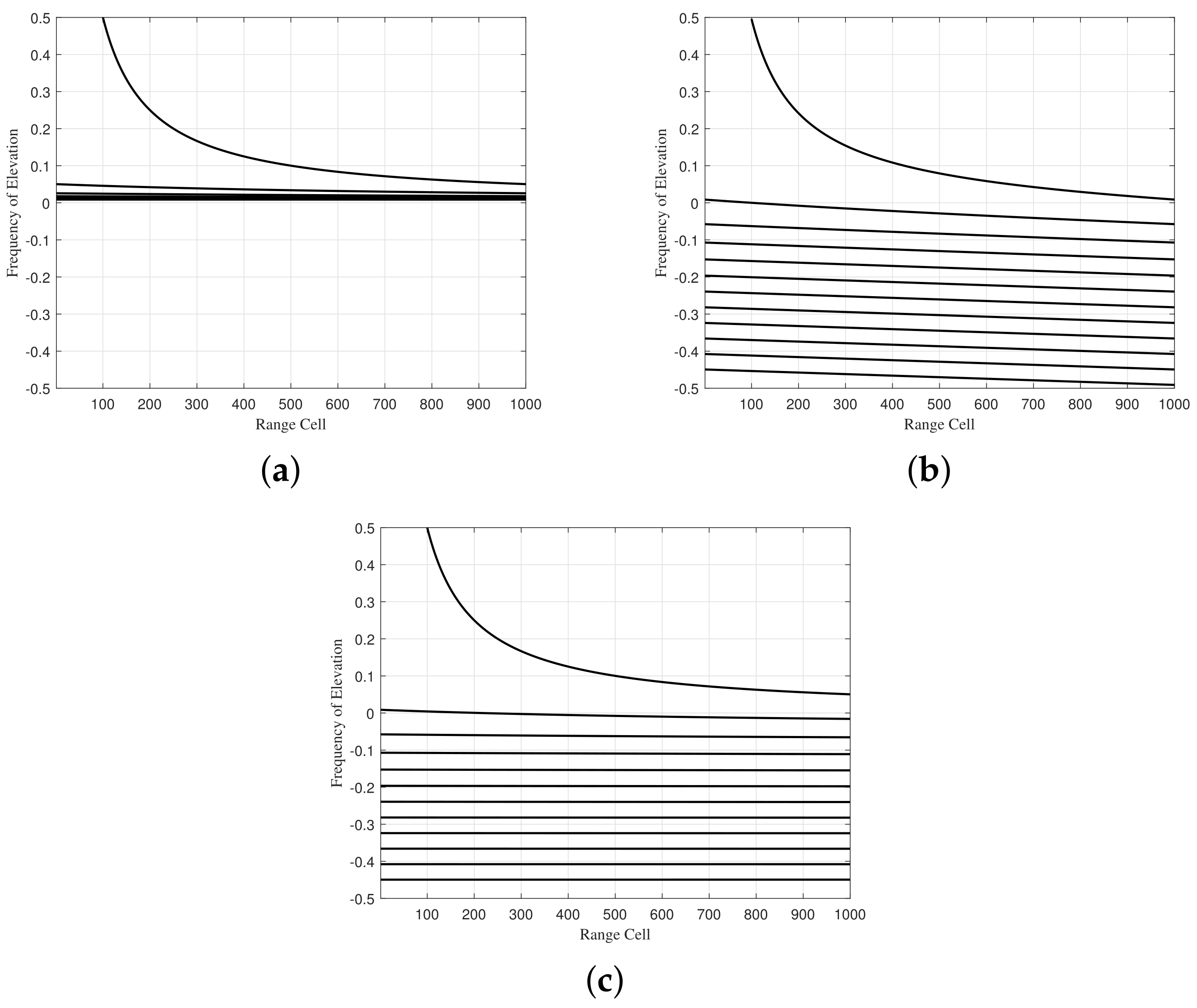
4.2. Clutter Separation

The second experiment analyzes the separation of range-ambiguous clutter using the proposed method compared to the CBF method, including both the CBF method and the improved CBF method. Considering the extraction of clutter in the first range-ambiguous region, Figure 4a,c,e show the clutter distribution after processing with the CBF method, the improved CBF method, and the proposed method, respectively. It is observed that the clutter from the first ambiguous region is successfully extracted. Since the clutter in the first ambiguous region is primarily composed of range-dependent clutter, the clutter spectrum exhibits significant diffusion.
Doppler Wrapping (DW) processing is required to align the spatial-temporal spectrum with the beam center, compensating for the range dependence of the clutter caused by the geometry of the airborne FDA radar. Figure 4b shows significant diffusion of the center clutter spectrum after DW processing, because the CBF method extracts near-range clutter along with range-ambiguous clutter, causing the DW technique to fail. In contrast, Figure 4d,f shows the center-aligned spatial-temporal spectrum after DW compensation for the improved CBF method and the proposed method, respectively. These figures indicate that both the improved CBF method and the proposed method can effectively extract clutter from the first ambiguous region.
Then, let us consider the clutter extraction in the third ambiguous region. Figure 5a illustrates the clutter spectrum using the CBF method in airborne FDA radar. It is observed that the performance of the CBF method significantly degrades because the extracted clutter contains a significant amount of near-range clutter. Figure 5b presents the clutter spectrum after the improved CBF method. It shows that the clutter spectrum is focused and demonstrates performance superior to the CBF method. However, a tiny amount of residual near-range clutter remains after the improved CBF method processing. Figure 5c shows the clutter spectrum after the proposed method. It is seen that, after the elevation filter, the range of ambiguous clutter can also be separated. The separated clutter, mainly from far ranges and not affected by distance, closely matches the IID condition, resulting in a space-time spectrum shown as a single curve.

4.3. SCNR Loss

SCNR Loss is an important performance metric for STAP, defined as the ratio of the output SCNR to the optimal SCNR, specifically
SCNR Loss = σ n 2 w H s s t 2 w H R w s s t H s s t
where w C N K × 1 is the weight of STAP, σ n 2 is the power of noise, s s t C N K × 1 is the space-time steering vector, and R C N K × N K is the signal covariance matrix.
To further validate the performance of the proposed method, Figure 6 presents the Signal-to-Clutter-plus-Noise Ratio (SCNR) loss curve. This figure compares the SCNR loss for several methods, including the conventional beamforming (CBF) method, the improved CBF method, and the proposed method, both with and without clutter compensation. Figure 6a shows the SCNR loss performance comparison in the first range-ambiguous region. It is evident that applying STAP directly to the separated clutter in this region results in a very wide null, which adversely affects target detection. Figure 6b displays the SCNR loss performance comparison in the third range-ambiguous region, with the ideal curve provided as a benchmark. The proposed method outperforms both the CBF and improved CBF methods in terms of SCNR loss and closely approaches the ideal FDA SCNR loss. This indicates that the proposed method effectively enhances target detection performance. Overall, the proposed STAP pre-processing method for separating range-ambiguous clutter demonstrates a significant improvement in target detection capabilities.

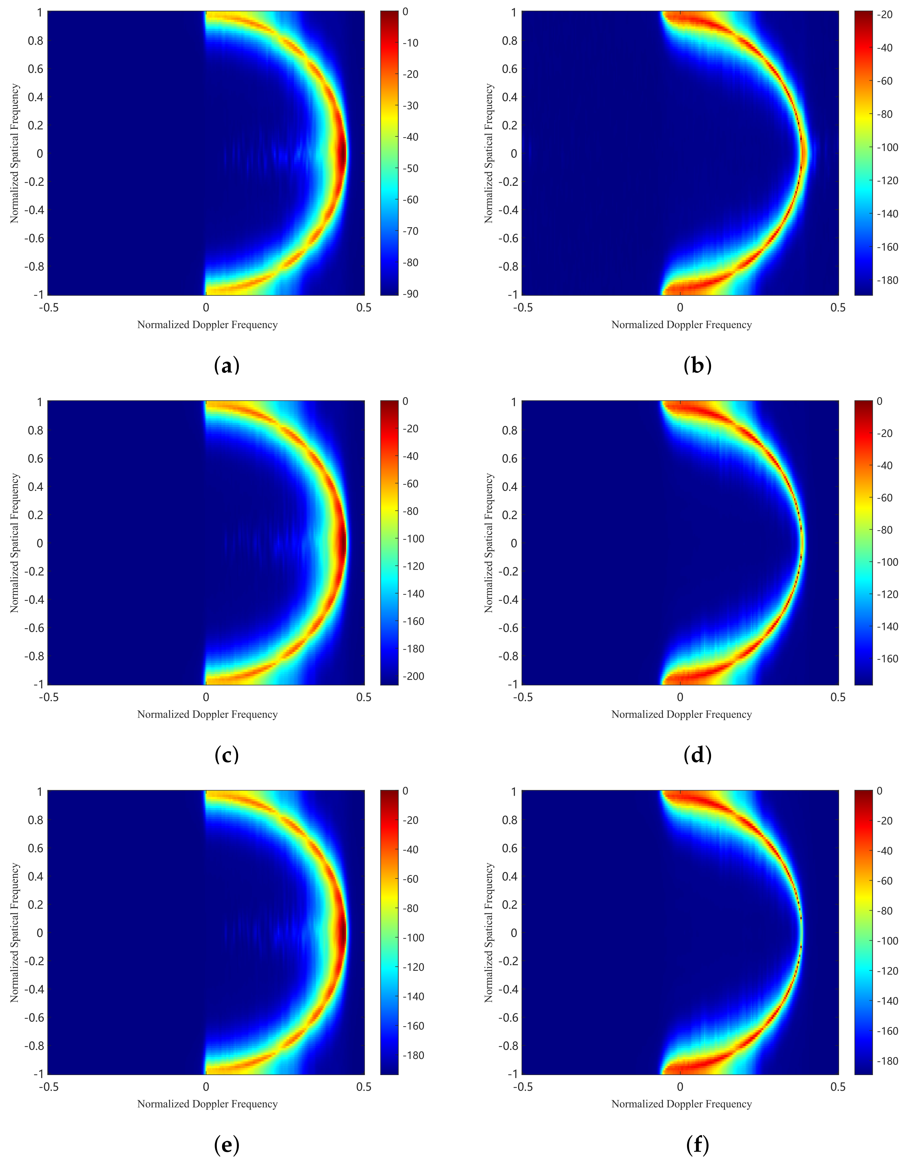
4.4. Clutter Suppression Performance

The third experiment evaluates the suppression performance of range-ambiguous clutter through range-Doppler spectrum analysis. In this setup, a target is positioned at the 200th range gate in the third ambiguous zone, with a normalized Doppler frequency of 0.35 and a SNR of 20 dB.
Figure 7a shows the RD spectrum after the CBF method processing, where clutter from near and far ranges overlap due to range ambiguity. It causes the RD spectrum to spread severely, making it difficult to detect the target. Figure 7b shows the RD spectrum after the improved CBF method processing. The beam response analysis shows that the CBF method only achieves high gain in the desired clutter region and fails to effectively notch near-range clutter, resulting in inadequate suppression of near-range clutter. Figure 7c shows the RD spectrum after the proposed method processing. The proposed method achieves high gain in the desired clutter region and forms significant notches in near-range and other ambiguous regions, thus more effectively suppressing near-range clutter. Additionally, target information is not discernible from the RD spectrum after processing with the CBF and improved CBF methods, as shown in Figure 7a,b. However, most of the short-range clutter is eliminated with the proposed method, as shown in Figure 7c, making the target more detectable than before.

5. Conclusions

In this paper, we consider range-ambiguous clutter suppression in airborne FDA radar. We propose a cascade method that combines elevation filtering and azimuth Doppler STAP to suppress range-dependent clutter. FDA quadratic range dependence compensation addresses the range-angle coupling problem in FDA radar and extends over the full spatial frequency. An oblique subspace projection can project the received signal onto the subspace spanned by the undesired signals, thus calculating the optimal adaptive weight vector for the height adaptive filter. After the elevation pre-filtering, the traditional azimuth Doppler STAP removes the remaining desired clutter for further suppression. Experimental simulations validate the effectiveness of this method in dealing with severe range ambiguity, with significant improvements in clutter suppression and target detection capabilities.

Author Contributions

Conceptualization, R.L. and Y.W.; methodology, L.Z.; software, R.L.; validation, R.L., Y.W. and L.Z.; formal analysis, Z.C.; investigation, R.L.; resources, Y.W.; data curation, R.L.; writing—original draft preparation, R.L.; writing—review and editing, R.L. and Y.W.; visualization, R.L. and Y.W.; supervision, R.L. and Y.W.; project administration, Y.W.; funding acquisition, Y.W. All authors have read and agreed to the published version of the manuscript.

Funding

The work was supported in part by the National Natural Science Foundation of China (62101603, 62201623), the Insight Action (62502010220), and the Science and Technology Planning Project of Key Laboratory of Advanced IntelliSense Technology Guangdong Science and Technology Department (2023B1212060024) (Corresponding author: Yifeng Wu).

Data Availability Statement

The original contributions presented in the study are included in the article, further inquiries can be directed to the corresponding author.

Conflicts of Interest

The authors declare no conflicts of interest.

References

  1. Li, Y.; Huo, T.; Yang, C.; Wang, T.; Wang, J.; Li, B. An efficient ground moving target imaging method for airborne circular stripmap sar. Remote Sens. 2022, 14, 210. [Google Scholar] [CrossRef]
  2. Han, J.; Cao, Y.; Wu, W.; Wang, Y.; Yeo, T.S.; Liu, S.; Wang, F. Robust gmti scheme for highly squinted hypersonic vehicle-borne multichannel sar in dive mode. Remote Sens. 2021, 13, 4431. [Google Scholar] [CrossRef]
  3. Li, H.; Liao, G.; Xu, J.; Lan, L. An efficient maritime target joint detection and imaging method with airborne isar system. Remote Sens. 2022, 14, 193. [Google Scholar] [CrossRef]
  4. Guerci, J. Space-Time Adaptive Processing for Radar, 2nd ed.; Artech: McLean, VA, USA, 2014. [Google Scholar]
  5. Huang, P.H.; Yang, H.; Zou, Z.; Xia, X.-G.; Liao, G.; Zhang, Y. Range-Ambiguous Sea Clutter Suppression for Multi-channel Spaceborne Radar Applications Via Alternating APC Processing. IEEE Trans. Aerosp. Electron. Syst. 2023, 59, 6954–6970. [Google Scholar] [CrossRef]
  6. Huang, P.H.; Zou, Z.; Xia, X.-G.; Liu, X.; Liao, G. A Novel Dimension-Reduced Space–Time Adaptive Processing Algorithm for Spaceborne Multichannel Surveillance Radar Systems Based on Spatial–Temporal 2-D Sliding Window. IEEE Trans. Geosci. Remote Sens. 2022, 60, 1–21. [Google Scholar] [CrossRef]
  7. Huang, P.H.; Zou, Z.; Xia, X.-G.; Liu, X.; Liao, G.; Xin, Z. Multichannel Sea Clutter Modeling for Spaceborne Early Warning Radar and Clutter Suppression Performance Analysis. IEEE Trans. Geosci. Remote Sens. 2021, 59, 8349–8366. [Google Scholar] [CrossRef]
  8. Miao, L.; Zhang, S.; Huang, L.; Ding, J.; Wang, W.Q. Moving target detection using fda-mimo radar with planar array. IEEE Geosci. Remote Sens. Lett. 2024, 21, 1–5. [Google Scholar] [CrossRef]
  9. Cui, N.; Duan, K.; Xing, K.; Yu, Z. Beam-space reduced-dimension 3d-stap for nonside-looking airborne radar. IEEE Geosci. Remote Sens. Lett. 2021, 19, 1–5. [Google Scholar] [CrossRef]
  10. Chen, W.; Xie, W.; Wang, Y. Short-range clutter suppression for airborne radar using sparse recovery and orthogonal projection. IEEE Geosci. Remote Sens. Lett. 2022, 19, 1–5. [Google Scholar] [CrossRef]
  11. Wang, X.; Ruan, Y.; Zhang, X. Effective non-stationary clutter suppression method via elevation oblique subspace projection for moving targets detection with a space-based surveillance radar. Electronics 2023, 12, 3110. [Google Scholar] [CrossRef]
  12. Meng, X.; Wang, T.; Wu, J.; Bao, Z. Short-range clutter suppression for airborne radar by utilizing prefiltering in elevation. IEEE Geosci. Remote Sens. Lett. 2009, 6, 268–272. [Google Scholar] [CrossRef]
  13. Shen, M.; Meng, X.; Zhang, L. Efficient adaptive approach for airborne radar short-range clutter suppression. IET Radar Sonar Navig. 2012, 6, 900–904. [Google Scholar] [CrossRef]
  14. Shen, M.; Meng, X.; Zhang, L. Clutter suppression algorithm for non-side looking airborne radar with high pulse repetition frequency based on elevation–compensation–prefiltering. IET Radar Sonar Navig. 2020, 14, 19–26. [Google Scholar]
  15. Antonik, P.; Wicks, M.C.; Griffiths, H.D.; Baker, C.J. Multi-mission multi-mode waveform diversity. In Proceedings of the 2006 IEEE Conference on Radar, Verona, NY, USA, 24–27 April 2006; p. 14. [Google Scholar]
  16. Xu, J.; Zhu, S.; Liao, G. Range ambiguous clutter suppression for airborne fda-stap radar. IEEE J. Sel. Top. Signal Process. 2015, 9, 1620–1631. [Google Scholar] [CrossRef]
  17. Xu, J.; Liao, G.; So, H.C. Space-time adaptive processing with vertical frequency diverse array for range-ambiguous clutter suppression. IEEE Trans. Geosci. Remote Sens. 2016, 54, 5352–5364. [Google Scholar] [CrossRef]
  18. Qiu, Z.; Liao, Z.; Xu, J.; Duan, K. Range-ambiguous clutter suppression for space-based early warning radar using vertical fda and horizontal epc. IEEE Geosci. Remote Sens. Lett. 2023, 20, 1–5. [Google Scholar] [CrossRef]
  19. Liu, Z.; Zhu, S.; Xu, J.; He, X.; Duan, K.; Lan, L. Range-ambiguous clutter suppression for stap-based radar with vertical coherent frequency diverse array. IEEE Trans. Geosci. Remote Sens. 2023, 61, 5106517. [Google Scholar] [CrossRef]
  20. Ward, J. Space-time adaptive processing for airborne radar. In Proceedings of the IEE Colloquium on Space-Time Adaptive Processing (Ref. No. 1998/241), London, UK, 6 April 1998; pp. 2/1–2/6. [Google Scholar]
  21. Behrens, R.T.; Scharf, L.L. Signal processing applications of oblique projection operators. IEEE Trans. Signal Process. 1994, 42, 1413–1424. [Google Scholar] [CrossRef]
Figure 1. The geometry of the airborne FDA radar.
Remotesensing 16 03198 g001
Figure 2. The variation in elevation frequency between PA and FDA. (a) PA. (b) FDA without compensation. (c) FDA with compensation.
Remotesensing 16 03198 g002
Figure 3. Beam response pattern. (a) FDA beam response diagram for the first ambiguous region. (b) PA beam response diagram for the first ambiguous region. (c) FDA beam response diagram for the third ambiguous region. (d) PA beam response diagram for the third ambiguous region. (e) Comparison of the beam response diagram at the 200th range gate for the first range region. (f) Comparison of the beam response diagram at the 200th range gate for the third range region.
Remotesensing 16 03198 g003
Figure 4. Clutter distribution for first range region. (a) The CBF method. (b) The CBF method and DW compensation. (c) The improved CBF method. (d) The improved CBF method with DW compensation. (e) The proposed method. (f) The proposed method with DW compensation.
Remotesensing 16 03198 g004
Figure 5. Clutter distribution for third range region. (a) The CBF method. (b) The improved CBF method. (c) The proposed method.
Remotesensing 16 03198 g005
Figure 6. SCNR loss performance comparison with different processing method versus normalized Doppler frequency. (a) First ambiguous range region. (b) Third ambiguous range region.
Remotesensing 16 03198 g006
Figure 7. Clutter distribution for third range region in joint horizontal spatial frequency and Doppler frequency domain. (a) The CBF method. (b) The improved CBF method. (c) The proposed method.
Remotesensing 16 03198 g007
Table 1. Simulation parameters of the airborne FDA radar system.
ParameterValue
Platform height1000 m
Platform velocity120 m/s
Number of element in azimuth12
Number of element in elevation24
Number of pulse in one CPI128
Input SNR20 dB
Input CNR60 dB
Bandwidth15 MHz
Pulse repetition frequency15,000 Hz
Reference frequency1 GHz
Frequency increment681 Hz
Disclaimer/Publisher’s Note: The statements, opinions and data contained in all publications are solely those of the individual author(s) and contributor(s) and not of MDPI and/or the editor(s). MDPI and/or the editor(s) disclaim responsibility for any injury to people or property resulting from any ideas, methods, instructions or products referred to in the content.

