
A First Extension of the Robust Satellite Technique RST-FLOOD to Sentinel-2 Data for the Mapping of Flooded Areas: The Case of the Emilia Romagna (Italy) 2023 Event


Abstract
:1. Introduction
2. Materials and Methods
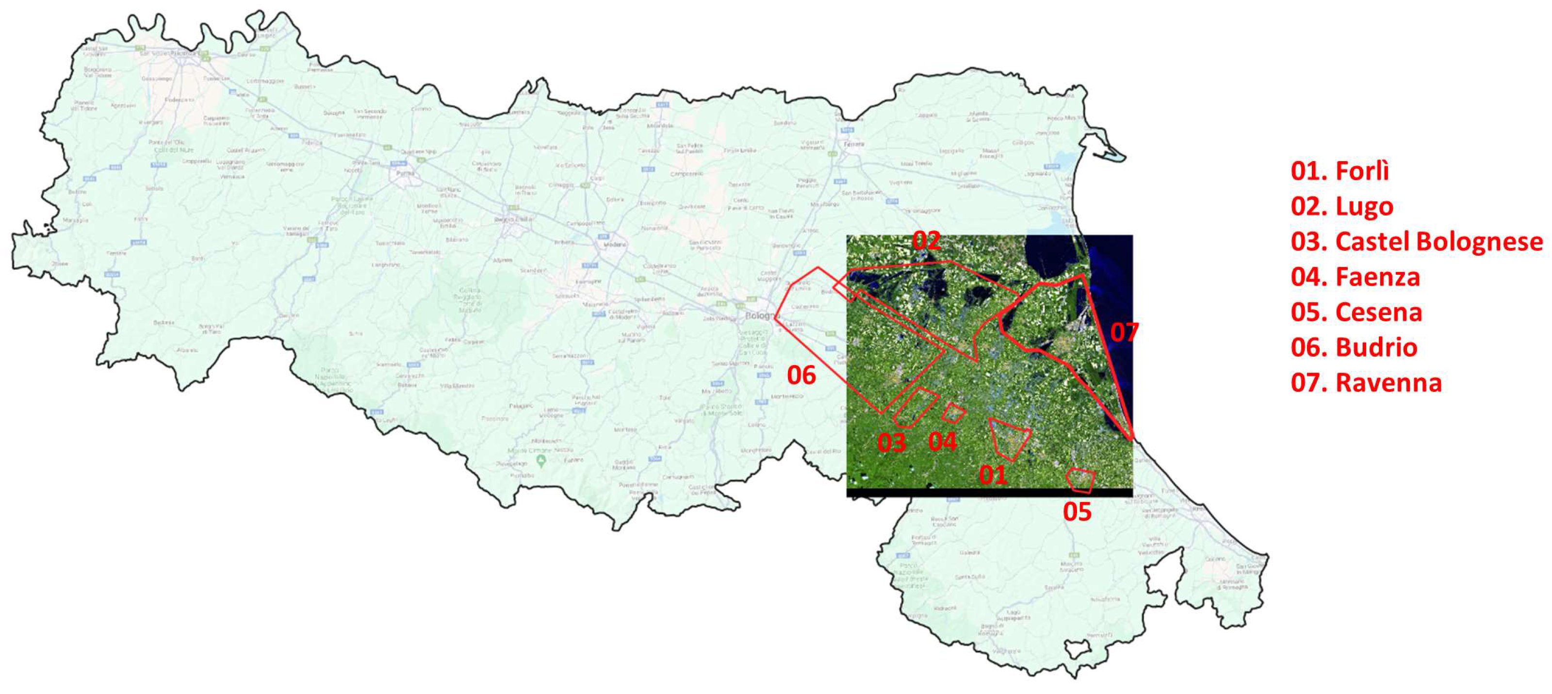
2.1. The Emilia Romagna (Italy) Flooding Event of May 2023
2.2. Data and Processing Techniques
2.2.1. Satellite Data and Products Used
2.2.2. RST-FLOOD
2.2.3. The [16] Technique
- -
- The first was the “Bright” spectral test:where:
- Rrs(λ) max is the maximum value of Rrs(λ).
- -
- The second was the “NIR peak” spectral test:where:
- RrsBLUE, RrsGREEN, RrsRED, and RrsNIR refer to 0.443, 0.560, 0.704, and 0.833 μm central wavelengths, respectively.
- -
- The third was the “Non-water” spectral test:where:
- RrsRED and RrsNIR refer to 0.704 and 0.833 μm, respectively.
- -
- The fourth was the “White” spectral test:where:
- Rrs(λ) max and Rrs(λ) min refer to the maximum and minimum values of Rrs(λ).
3. Results
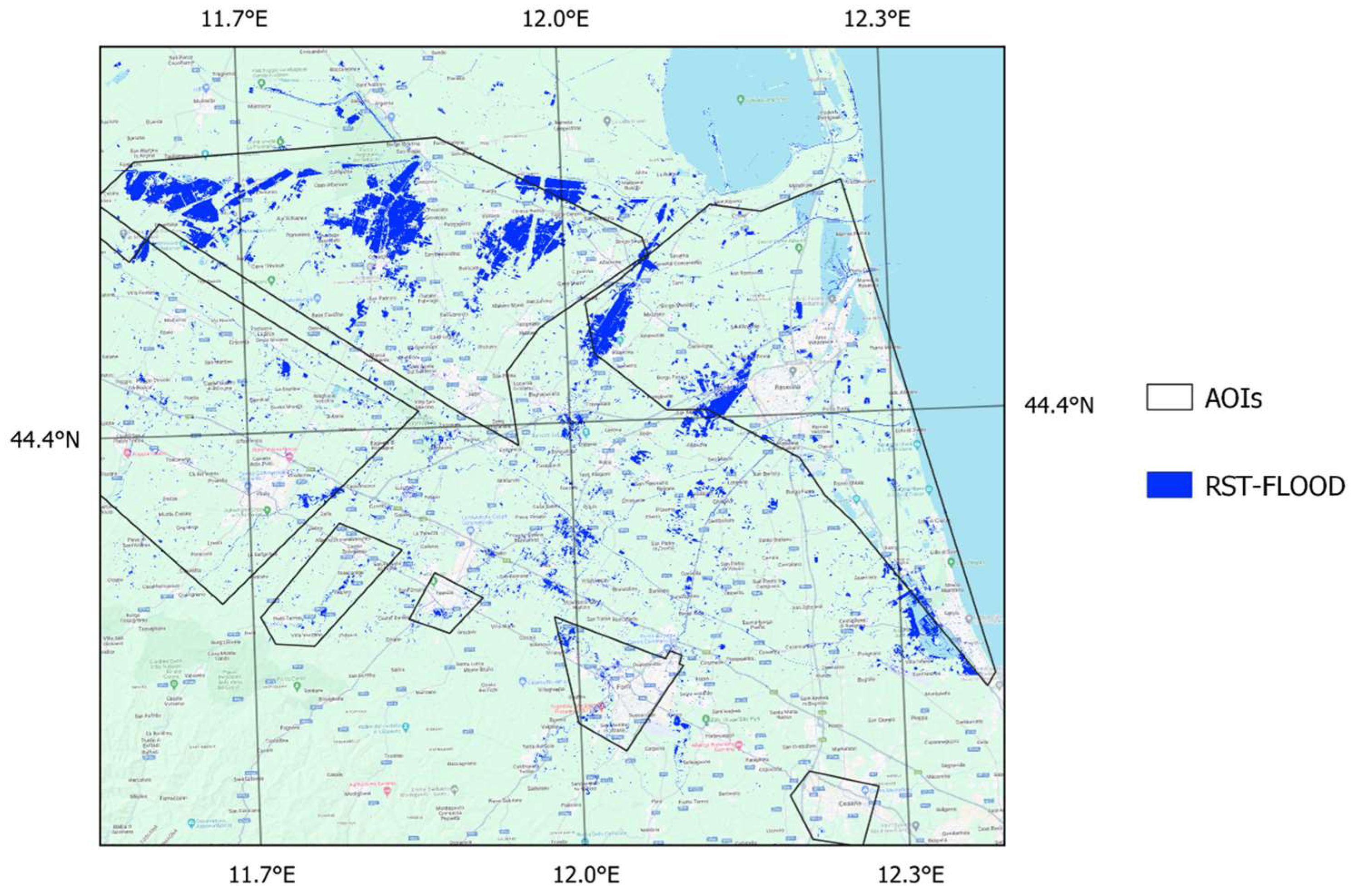
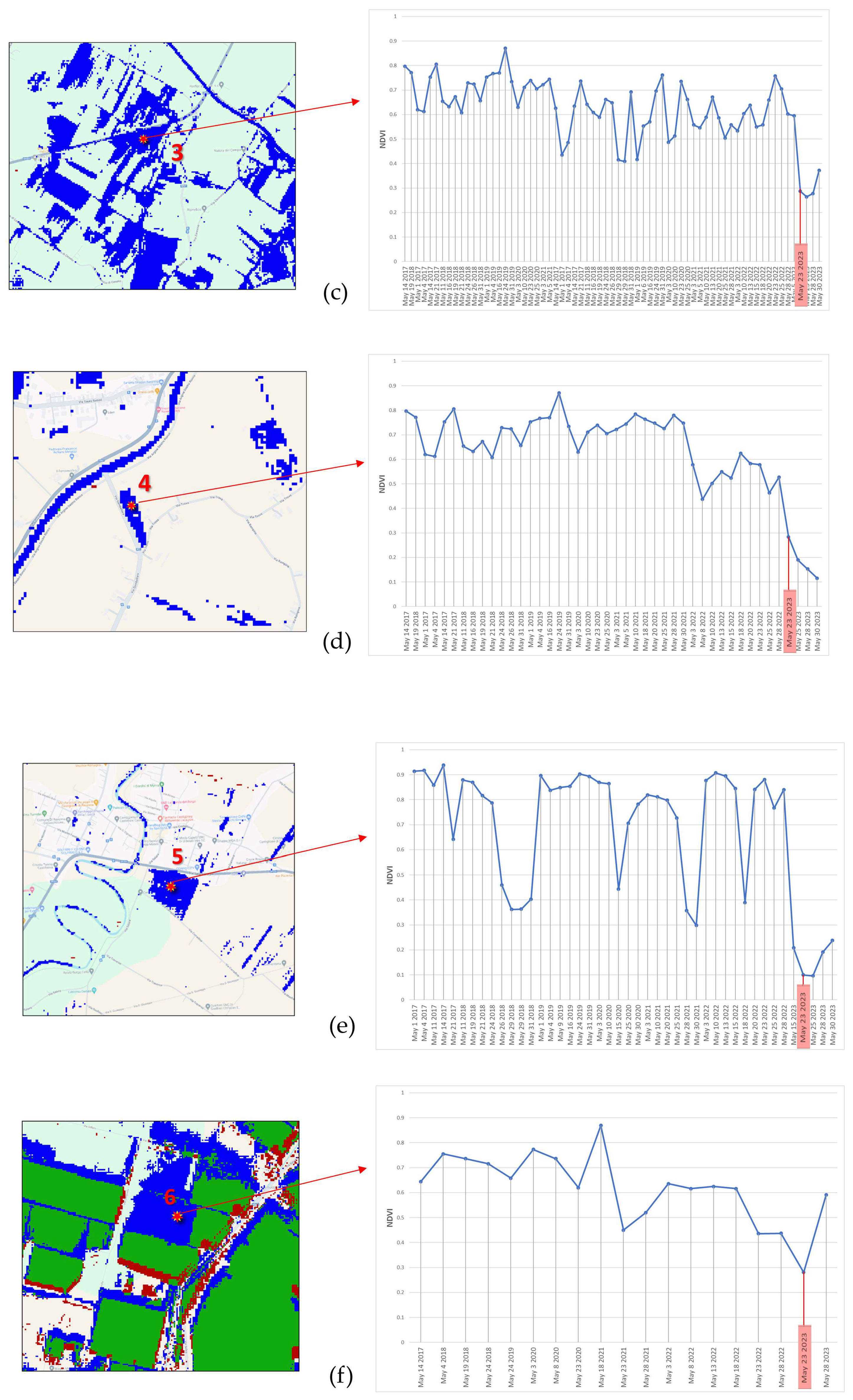
RST-FLOOD Results
4. Discussion
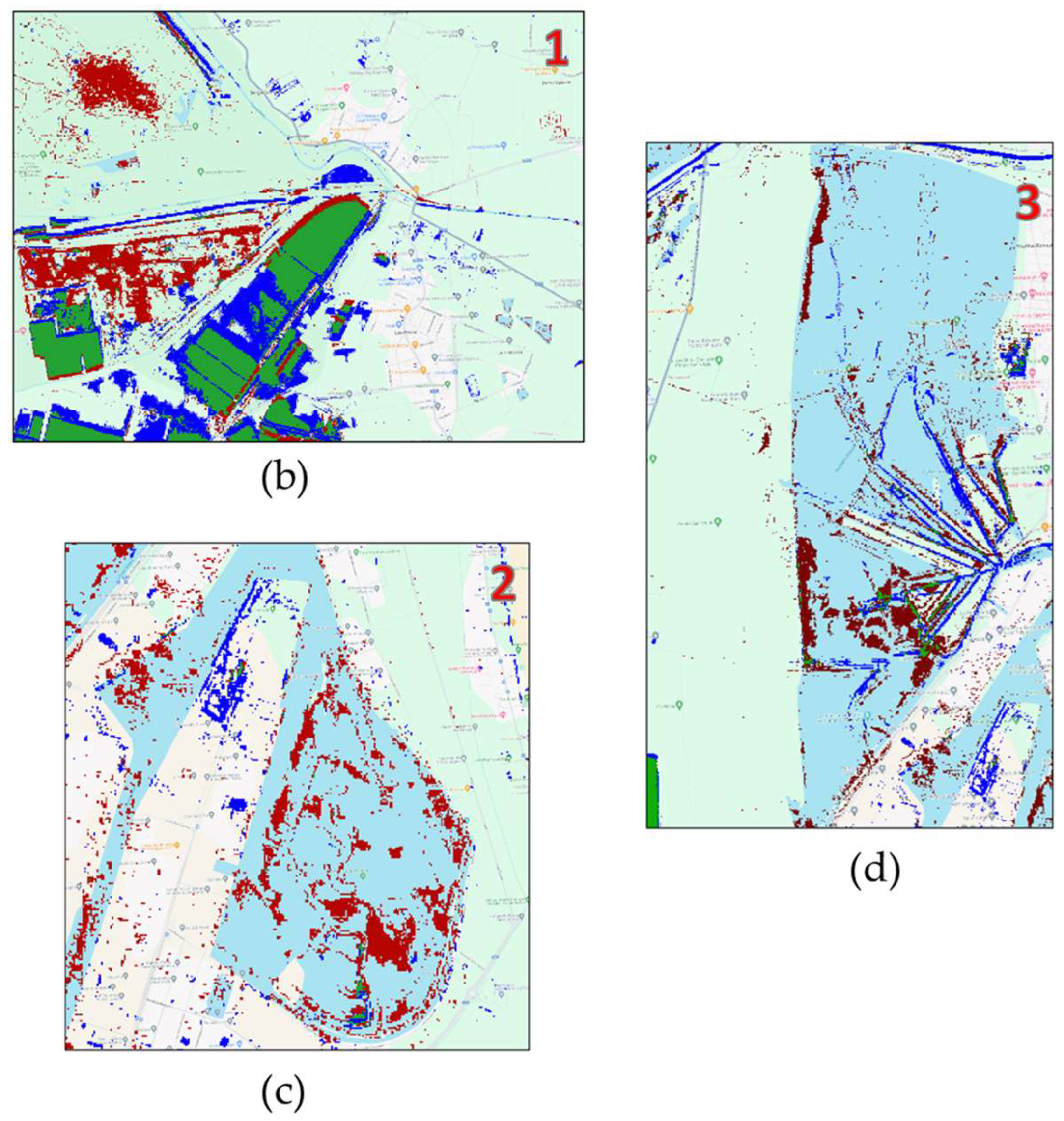
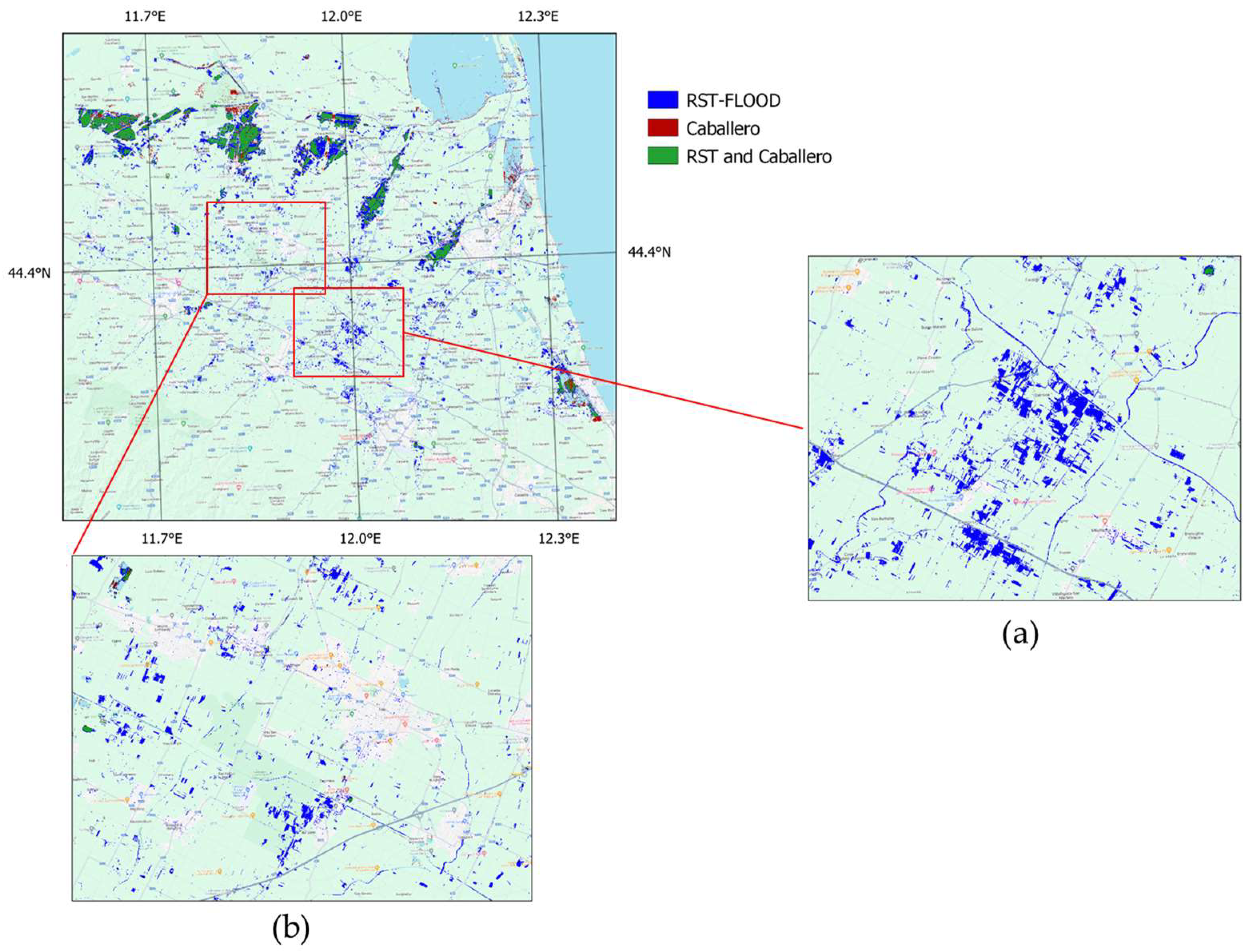
4.1. CAB Technique Implementation and Comparison with RST-FLOOD
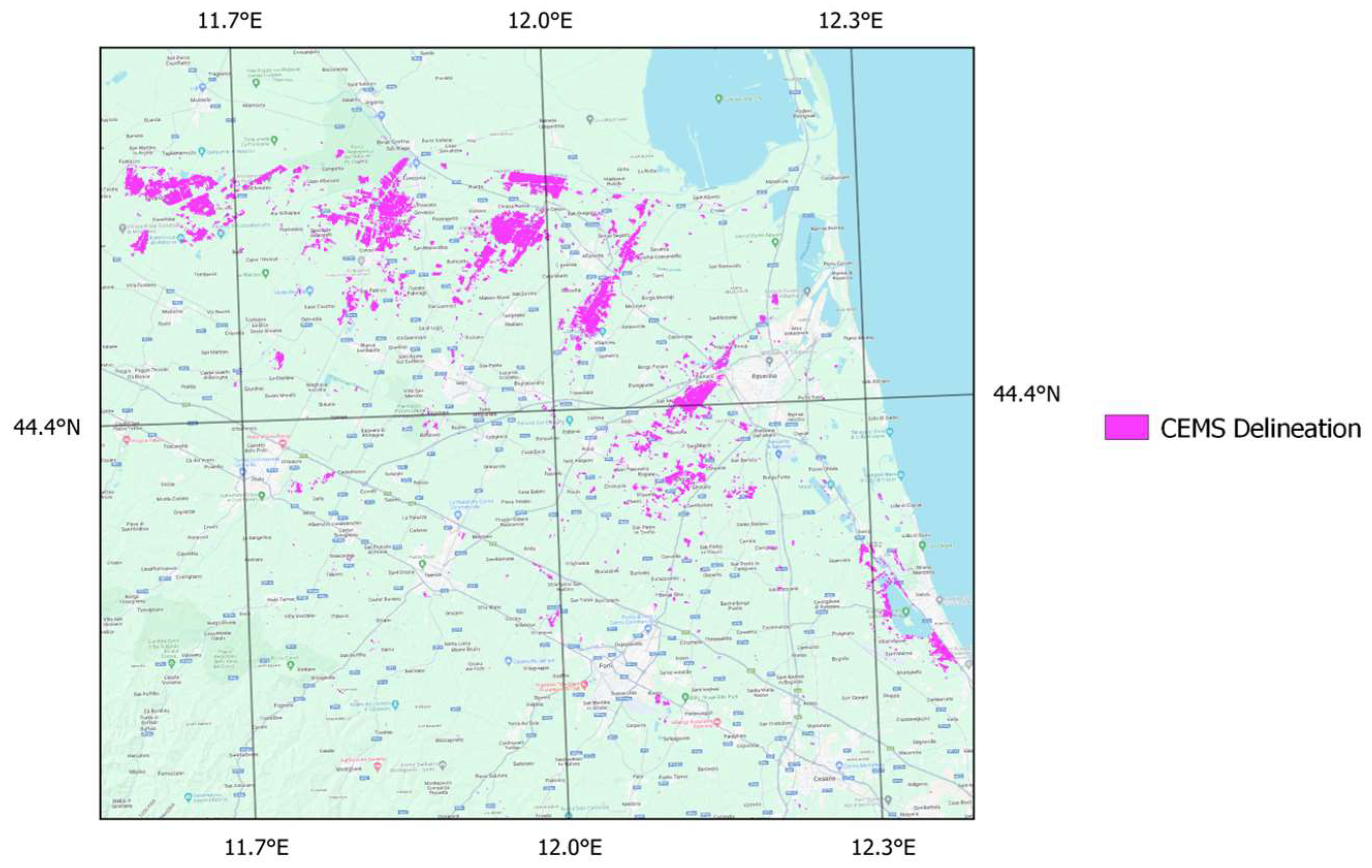
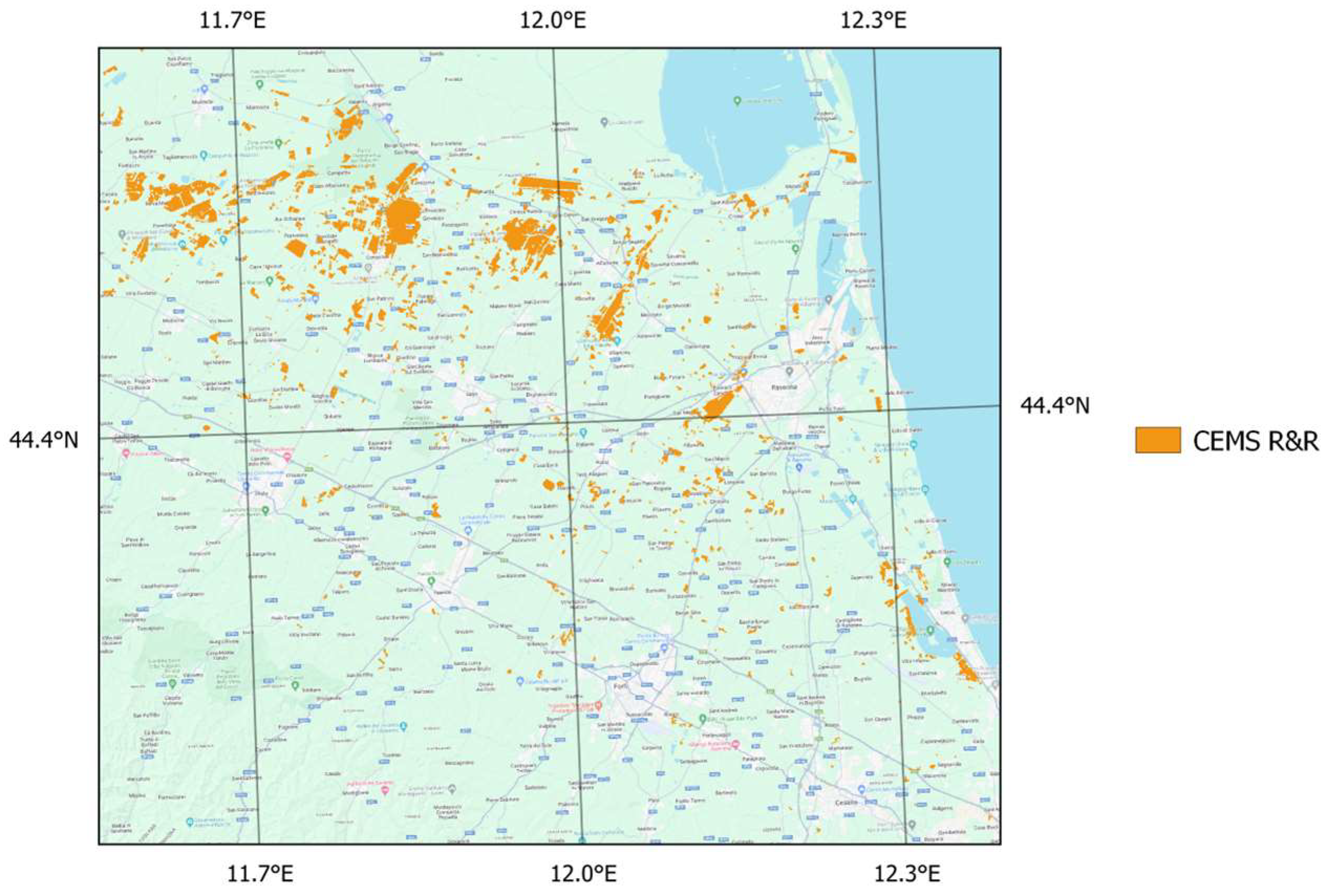
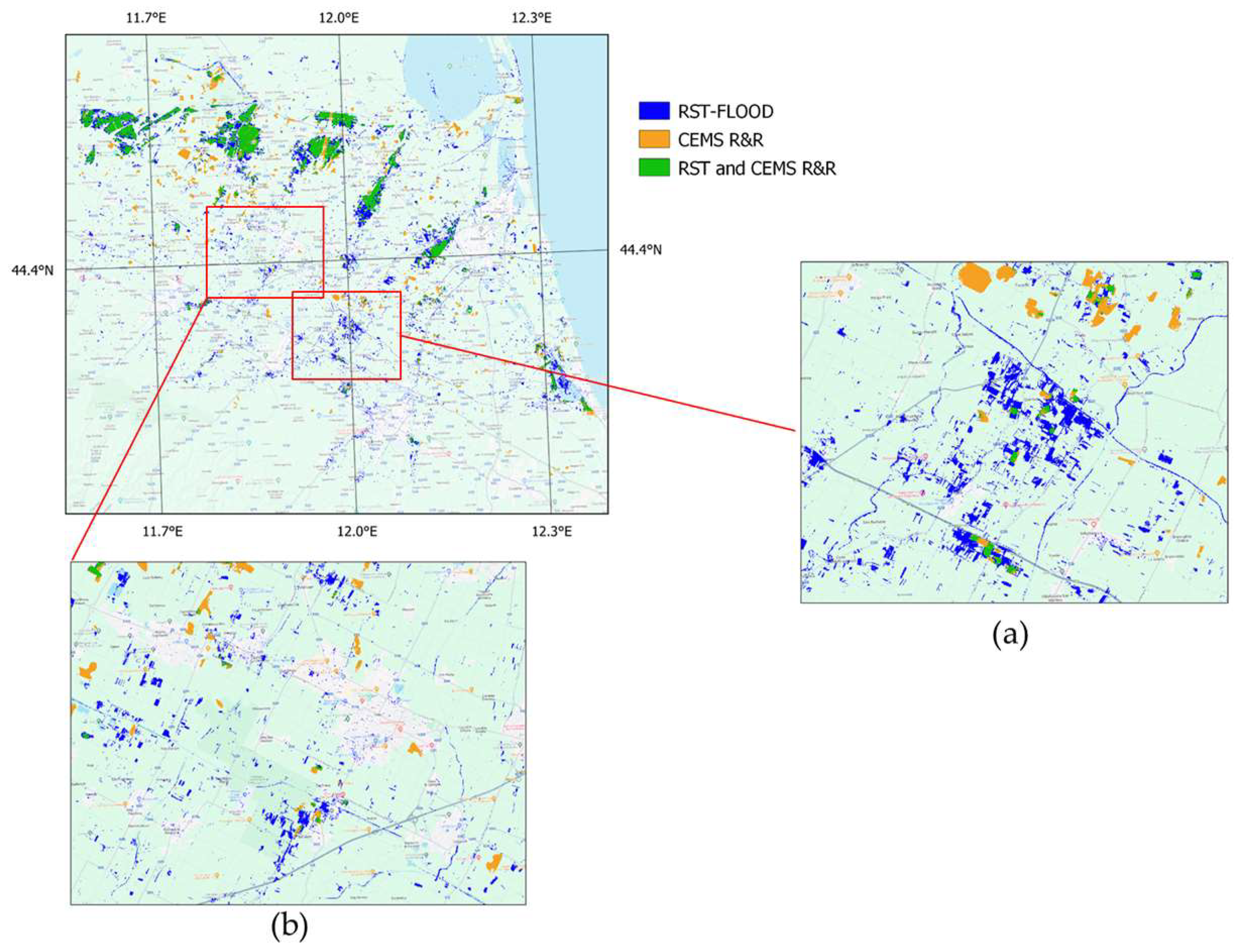
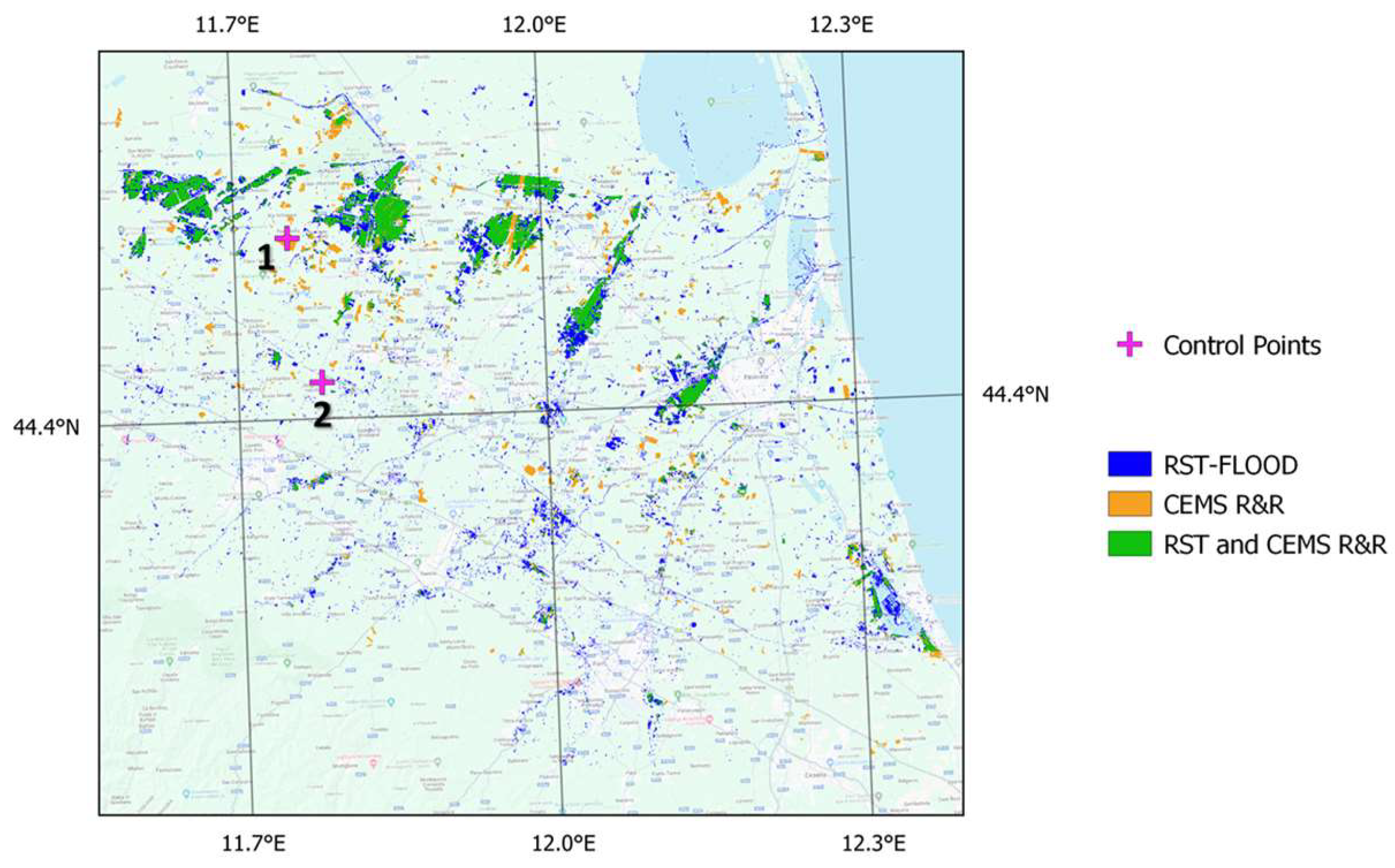
4.2. Comparison between RST-FLOOD and CEMS Products
5. Conclusions
Author Contributions
Funding
Data Availability Statement
Conflicts of Interest
References
- Hapuarachchi, H.A.P.; Wang, Q.J.; Pagano, T.C. A review of advances in flash flood forecasting. Hydrol. Process. 2011, 25, 2771–2784. [Google Scholar] [CrossRef]
- Markert, K.L.; Chishtie, F.; Anderson, E.R.; Saah, D.; Griffin, R.E. On the merging of optical and SAR satellite imagery for surface water mapping applications. Results Phys. 2018, 9, 275–277. [Google Scholar] [CrossRef]
- Dasgupta, A.; Grimaldi, S.; Ramsankaran, R.; Pauwels, V.R.N.; Walker, J.P.; Chini, M.; Hostache, R.; Matgen, P. Flood Mapping Using Synthetic Aperture Radar Sensors from Local to Global Scales. In Global Flood Hazard: Applications in Modeling, Mapping, and Forecasting, Geophysical Monograph 233, 1st ed.; John Wiley & Sons, Inc.: Hoboken, NJ, USA, 2018; ISBN 978-1-119-21786-2. [Google Scholar]
- Foroughnia, F.; Alfieri, S.M.; Menenti, M.; Lindenbergh, R. Evaluation of SAR and Optical Data for Flood Delineation Using Supervised and Unsupervised Classification. Remote Sens. 2022, 14, 3718. [Google Scholar] [CrossRef]
- Colosio, P.; Tedesco, M.; Tellman, E. Flood Monitoring Using Enhanced Resolution Passive Microwave Data: A Test Case over Bangladesh. Remote Sens. 2022, 14, 1180. [Google Scholar] [CrossRef]
- Amitrano, D.; Di Martino, G.; Di Simone, A.; Imperatore, P. Flood Detection with SAR: A Review of Techniques and Datasets. Remote Sens. 2024, 16, 656. [Google Scholar] [CrossRef]
- Bauer-Marschallinger, B.; Cao, S.; Tupas, M.E.; Roth, F.; Navacchi, C.; Melzer, T.; Freeman, V.; Wagner, W. Satellite-Based Flood Mapping through Bayesian Inference from a Sentinel-1 SAR Datacube. Remote Sens. 2022, 14, 3673. [Google Scholar] [CrossRef]
- Schlaffer, S.; Matgen, P.; Hollaus, M.; Wagner, W. Flood detection from multi-temporal SAR data using harmonic analysis and change detection. Int. J. Appl. Earth Obs. Geoinf. 2015, 38, 15–24. [Google Scholar] [CrossRef]
- Li, S.; Sun, D.; Goldberg, M.D.; Sjoberg, B.; Santek, D.; Hoffman, J.P.; DeWeese, M.; Restrepo, P.; Lindsey, S.; Holloway, E. Automatic near real-time flood detection using Suomi-NPP/VIIRS data. Remote Sens. Environ. 2018, 204, 672–689. [Google Scholar] [CrossRef]
- Huang, C.; Chen, Y.; Zhang, S.; Wu, J. Detecting, extracting, and monitoring surface water from space using optical sensors: A review. Rev. Geophys. 2018, 56, 333–360. [Google Scholar] [CrossRef]
- Faruolo, M.; Coviello, I.; Lacava, T.; Pergola, N.; Tramutoli, V. A multi-sensor exportable approach for automatic flooded areas detection and monitoring by a composite satellite constellation. IEEE Trans. Geosci. Remote Sens. 2013, 51, 2136–2149. [Google Scholar] [CrossRef]
- Fayne, J.; Bolten, J.; Lakshmi, V.; Ahamed, A. Optical and Physical Methods for Mapping Flooding with Satellite Imagery. In Remote Sensing of Hydrological Extremes; Springer Remote Sensing/Photogrammetry; Lakshmi, V., Ed.; Springer International Publishing: Basel, Switzerland, 2017; Volume Chapter 5, pp. 83–103. [Google Scholar] [CrossRef]
- Kwak, Y. Nationwide Flood Monitoring for Disaster Risk Reduction Using Multiple Satellite Data. ISPRS Int. J. Geo-Inf. 2017, 6, 203. [Google Scholar] [CrossRef]
- Ogilvie, A.; Belaud, G.; Massuel, S.; Mulligan, M.; Le Goulven, P.; Calvez, R. Surface water monitoring in small water bodies: Potential and limits of multi-sensor Landsat time series. Hydrol. Earth Syst. Sci. 2018, 22, 4349–4380. [Google Scholar] [CrossRef]
- Cavallo, C.; Papa, M.N.; Gargiulo, M.; Palau-Salvador, G.; Vezza, P.; Ruello, G. Continuous Monitoring of the Flooding Dynamics in the Albufera Wetland (Spain) by Landsat-8 and Sentinel-2 Datasets. Remote Sens. 2021, 13, 3525. [Google Scholar] [CrossRef]
- Caballero, I.; Ruiz, J.; Navarro, G. Sentinel-2 satellites provide near-real time evaluation of catastrophic floods in the west mediterranean. Water 2019, 11, 2499. [Google Scholar] [CrossRef]
- Goffi, A.; Stroppiana, D.; Brivio, P.A.; Bordogna, G.; Boschetti, M. Towards an automated approach to map flooded areas from Sentinel-2 MSI data and soft integration of water spectral features. Int. J. Appl. Earth Obs. Geoinf. 2020, 84, 101951. [Google Scholar] [CrossRef]
- Marc, W.; Martinis, S. A modular processing chain for automated flood monitoring from multi-spectral satellite data. Remote Sens. 2020, 11, 2330. [Google Scholar] [CrossRef]
- Copernicus Sentinel-1 Mission. Available online: https://sentinels.copernicus.eu/web/sentinel/missions/sentinel-1 (accessed on 18 July 2024).
- Chang, S.; Deng, Y.; Zhang, Y.; Zhao, Q.; Wang, R.; Zhang, K. An advanced scheme for range ambiguity suppression of spaceborne SAR based on blind source separation. IEEE Trans. Geosci. Remote Sens. 2022, 60, 1–12. [Google Scholar] [CrossRef]
- Pradhan, B.; Tehrany, M.S.; Jebur, M.N. A New Semiautomated Detection Mapping of Flood Extent from TerraSAR-X Satellite Image Using Rule-Based Classification and Taguchi Optimization Techniques. IEEE Trans. Geosci. Remote Sens. 2016, 54, 4331–4342. [Google Scholar] [CrossRef]
- Salamon, P.; Mctlormick, N.; Reimer, C.; Clarke, T.; Bauer-Marschallinger, B.; Wagner, W.; Martinis, S.; Chow, C.; Böhnke, C.; Matgen, P.; et al. The New, Systematic Global Flood Monitoring Product of the Copernicus Emergency Management Service. In Proceedings of the 2021 IEEE International Geoscience and Remote Sensing Symposium IGARSS, Brussels, Belgium, 11–16 July 2021; IEEE: Piscataway, NJ, USA, 2021; pp. 1053–1056. [Google Scholar] [CrossRef]
- Global Flood Awareness System (GloFAS) for Copernicus Emergency Management Service (CEMS). Available online: https://global-flood.emergency.copernicus.eu/ (accessed on 1 August 2024).
- Schumann, G.P.; Brakenridge, G.R.; Kettner, A.J.; Kashif, R.; Niebuhr, E. Assisting Flood Disaster Response with Earth Observation Data and Products: A Critical Assessment. Remote Sens. 2018, 10, 1230. [Google Scholar] [CrossRef]
- Wang, Q.; Watanabe, M.; Hayashi, S.; Murakami, S. Using NOAA AVHRR data to assess flood damage in China. Environ. Monit. Assess. 2003, 82, 119–148. [Google Scholar] [CrossRef]
- Jain, S.K.; Saraf, A.K.; Goswami, A.; Ahmad, T. Flood inundation mapping using NOAA AVHRR data. Water Resour. Manag. 2006, 20, 949–959. [Google Scholar] [CrossRef]
- Rahman, M.S.; Di, L. The state of the art of spaceborne remote sensing in flood management. Nat. Hazards 2017, 85, 1223–1248. [Google Scholar] [CrossRef]
- Brakenridge, R.; Anderson, E. MODIS-based flood detection, mapping and measurement: The potential for operational hydrological applications. In Transboundary Floods: Reducing Risks through Flood Management; Springer: Dutch, The Netherlands, 2006; pp. 1–12. [Google Scholar] [CrossRef]
- Ahamed, A.; Bolten, J.D. A MODIS-based automated flood monitoring system for southeast asia. Int. J. Appl. Earth Obs. Geoinf. 2017, 61, 104–117. [Google Scholar] [CrossRef]
- Copernicus Web Site. Available online: https://sentinels.copernicus.eu/web/sentinel/home (accessed on 1 August 2024).
- Copernicus Emergency Management Service Website. Available online: https://emergency.copernicus.eu/ (accessed on 18 July 2024).
- CEMS Rapid Mapping Portfolio. Available online: https://emergency.copernicus.eu/mapping/ems/rapid-mapping-portfolio (accessed on 18 July 2024).
- CEMS Risk and Recovery Portfolio. Available online: https://emergency.copernicus.eu/mapping/ems/risk-and-recovery-mapping-portfolio (accessed on 18 July 2024).
- Lacava, T.; Ciancia, E.; Faruolo, M.; Pergola, N.; Satriano, V.; Tramutoli, V. On the potential of RST-FLOOD on visible infrared imaging radiometer suite data for flooded areas detection. Remote Sens. 2019, 11, 598. [Google Scholar] [CrossRef]
- Lacava, T.; Filizzola, C.; Pergola, N.; Sannazzaro, F.; Tramutoli, V. Improving flood monitoring by the Robust AVHRR Technique (RAT) approach: The case of the April 2000 Hungary flood. Int. J. Remote Sens. 2010, 31, 2043–2062. [Google Scholar] [CrossRef]
- Valente, M.; Zanellati, M.; Facci, G.; Zanna, N.; Petrone, E.; Moretti, E.; Ragazzoni, L. Health System Response to the 2023 Floods in Emilia-Romagna, Italy: A Field Report. Prehospital Disaster Med. 2023, 38, 813–817. [Google Scholar] [CrossRef]
- Agenzia per la Sicurezza Territoriale e Protezione Civile. Available online: https://protezionecivile.regione.emilia-romagna.it/notizie/2023/maggio/copy_of_alluvione-sanita-proroga-pagamenti (accessed on 18 July 2024).
- Il Resto del Carlino Journal Website. Available online: https://www.ilrestodelcarlino.it/emilia-romagna/cronaca/alluvione-emilia-romagna-numeri-cml6u604 (accessed on 18 July 2024).
- Agenzia per la Sicurezza Territoriale e Protezione Civile. Available online: https://protezionecivile.regione.emilia-romagna.it/notizie/2023/maggio/36000-persone-evacuate-20-maggio-allagamenti-aggiuntivi-a-ravenna (accessed on 18 July 2024).
- Copernicus Sentinel-2 Mission. Available online: https://sentinels.copernicus.eu/web/sentinel/missions/sentinel-2 (accessed on 18 July 2024).
- Copernicus Sentinel-2 User Guide. Available online: https://sentinels.copernicus.eu/web/sentinel/user-guides/sentinel-2-msi (accessed on 18 July 2024).
- Copernicus Sentinel-2 Data Products. Available online: https://sentinels.copernicus.eu/web/sentinel/missions/sentinel-2/data-products (accessed on 18 July 2024).
- Copernicus Sentinel-2 Processing Levels. Available online: https://sentinel.esa.int/web/sentinel/user-guides/sentinel-2-msi/processing-levels/level-2 (accessed on 18 July 2024).
- Copernicus Emergency Management Service (CEMS) Emilia Romagna Event. Available online: https://rapidmapping.emergency.copernicus.eu/EMSR664/download (accessed on 18 July 2024).
- Technical Report for Emilia Romagna Event. Available online: https://emergency.copernicus.eu/mapping/list-of-components/EMSN154 (accessed on 18 July 2024).
- Copernicus Emergency Management Service Bulletin. Available online: https://emergency.copernicus.eu/mapping/ems/information-bulletin-167-copernicus-emergency-management-service-activities-following-latest (accessed on 18 July 2024).
- Tramutoli, V. Robust satellite techniques (RST) for natural and environmental hazards monitoring and mitigation: Theory and applications. In Proceedings of the 2007 International Workshop on the Analysis of Multi-Temporal Remote Sensing Images, Leuven, Belgium, 18–20 July 2007; IEEE: Piscataway, NJ, USA, 2007. [Google Scholar] [CrossRef]
- Dozier, J. Spectral signature of alpine snow cover from the Landsat thematic mapper. Remote Sens. Environ. 1989, 28, 9–22. [Google Scholar] [CrossRef]
- Google Earth Engine Website. Available online: https://earthengine.google.com/ (accessed on 18 July 2024).
- Copernicus Sentinel-2 Harmonized Product Description on GEE. Available online: https://developers.google.com/earth-engine/datasets/catalog/COPERNICUS_S2_SR_HARMONIZED#bands (accessed on 18 July 2024).
- Copernicus Sentinel-2 Cloud Masks Description on GEE. Available online: https://sentinel.esa.int/web/sentinel/technical-guides/sentinel-2-msi/level-1c/cloud-masks (accessed on 18 July 2024).
- Copernicus Sentinel-2 Cloud Probability Product Description on GEE. Available online: https://developers.google.com/earth-engine/datasets/catalog/COPERNICUS_S2_CLOUD_PROBABILITY (accessed on 18 July 2024).
- Cuomo, V.; Filizzola, C.; Pergola, N.; Pietrapertosa, C.; Tramutoli, V. A self-sufficient approach for GERB cloudy radiance detection. Atmos. Res. 2004, 72, 39–56. [Google Scholar] [CrossRef]
- Pietrapertosa, C.; Pergola, N.; Lanorte, V.; Tramutoli, V. Self Adaptive Algorithms for Change Detection: OCA (the One-channel Cloud-detection Approach) an adjustable method for cloudy and clear radiances detection. In Proceedings of the Technical Proceedings of the Eleventh International (A)TOVS Study Conference (ITSC-XI), Budapest, Hungary, 20–26 September 2000; pp. 281–291. [Google Scholar] [CrossRef]
- Lacava, T.; Marchese, F.; Pergola, N.; Tramutoli, V.; Coviello, I.; Faruolo, M.; Paciello, R.; Mazzeo, G. RSTVOLC implementation on MODIS data for monitoring of thermal volcanic activity. Ann. Geophys. 2011, 54. [Google Scholar] [CrossRef]
- ESA’s Science Hub Web Portal. Available online: https://dataspace.copernicus.eu/ (accessed on 1 August 2024).
- Vanhellemont, Q. Adaptation of the Dark Spectrum Fitting Atmospheric Correction for Aquatic Applications of the Landsat and Sentinel-2 Archives. Remote Sens. Environ. 2019, 225, 175–192. [Google Scholar] [CrossRef]
- Ente Parco del Po Website. Available online: https://www.parcodeltapo.it/it/IT4060001.php (accessed on 18 July 2024).
- Ente Parco del Po Website. Available online: https://www.parcodeltapo.it/it/IT4070006.php (accessed on 18 July 2024).
- Ravenna Tourism Website. Available online: https://www.turismo.ra.it/en/nature-seaside/natural-areas/pialassa-della-baiona/ (accessed on 18 July 2024).
- Rouse, J.W.; Haas, R.H.; Schell, J.A.; Deering, D.W. Monitoring vegetation systems in the Great Plains with ERTS. In Proceedings of the ERTS-1 Symposium 3rd, NASA, Greenbelt, MD, USA, 10–14 December 1974. [Google Scholar]
- Huang, S.; Tang, L.; Hupy, J.P.; Wang, Y.; Shao, G.F. A commentary review on the use of normalized difference vegetation index (NDVI) in the era of popular remote sensing. J. For. Res. 2021, 32, 1–6. [Google Scholar] [CrossRef]


| Name | Data Type | Technique Type | Delivery Time |
|---|---|---|---|
| CAB | Optical Data | Semi-automatic | 10 h |
| CEMS Delineation | SAR Data | Semi-automatic | 18–34 h |
| CEMS R&R | SAR Data | Semi-automatic | 2 months |
| RST-FLOOD | Optical Data | Fully automatic | 15 min |
| Flood Pixels Shared by Both Methods | RST-FLOOD Exclusive Detections | CAB Exclusive Detections |
|---|---|---|
| 29.3% | 58.9% | 11.8% |
Disclaimer/Publisher’s Note: The statements, opinions and data contained in all publications are solely those of the individual author(s) and contributor(s) and not of MDPI and/or the editor(s). MDPI and/or the editor(s) disclaim responsibility for any injury to people or property resulting from any ideas, methods, instructions or products referred to in the content. |
© 2024 by the authors. Licensee MDPI, Basel, Switzerland. This article is an open access article distributed under the terms and conditions of the Creative Commons Attribution (CC BY) license (https://creativecommons.org/licenses/by/4.0/).
Share and Cite
Satriano, V.; Ciancia, E.; Pergola, N.; Tramutoli, V. A First Extension of the Robust Satellite Technique RST-FLOOD to Sentinel-2 Data for the Mapping of Flooded Areas: The Case of the Emilia Romagna (Italy) 2023 Event. Remote Sens. 2024, 16, 3450. https://doi.org/10.3390/rs16183450
Satriano V, Ciancia E, Pergola N, Tramutoli V. A First Extension of the Robust Satellite Technique RST-FLOOD to Sentinel-2 Data for the Mapping of Flooded Areas: The Case of the Emilia Romagna (Italy) 2023 Event. Remote Sensing. 2024; 16(18):3450. https://doi.org/10.3390/rs16183450
Chicago/Turabian StyleSatriano, Valeria, Emanuele Ciancia, Nicola Pergola, and Valerio Tramutoli. 2024. "A First Extension of the Robust Satellite Technique RST-FLOOD to Sentinel-2 Data for the Mapping of Flooded Areas: The Case of the Emilia Romagna (Italy) 2023 Event" Remote Sensing 16, no. 18: 3450. https://doi.org/10.3390/rs16183450
APA StyleSatriano, V., Ciancia, E., Pergola, N., & Tramutoli, V. (2024). A First Extension of the Robust Satellite Technique RST-FLOOD to Sentinel-2 Data for the Mapping of Flooded Areas: The Case of the Emilia Romagna (Italy) 2023 Event. Remote Sensing, 16(18), 3450. https://doi.org/10.3390/rs16183450